EP1662516B1 - Gesinterter r-t-b-magnet und seltenerdlegierung - Google Patents
Gesinterter r-t-b-magnet und seltenerdlegierung Download PDFInfo
- Publication number
- EP1662516B1 EP1662516B1 EP04771704.6A EP04771704A EP1662516B1 EP 1662516 B1 EP1662516 B1 EP 1662516B1 EP 04771704 A EP04771704 A EP 04771704A EP 1662516 B1 EP1662516 B1 EP 1662516B1
- Authority
- EP
- European Patent Office
- Prior art keywords
- mass
- rare
- sintered magnet
- alloy
- phase
- Prior art date
- Legal status (The legal status is an assumption and is not a legal conclusion. Google has not performed a legal analysis and makes no representation as to the accuracy of the status listed.)
- Active
Links
- 229910045601 alloy Inorganic materials 0.000 title claims description 36
- 239000000956 alloy Substances 0.000 title claims description 36
- 229910052761 rare earth metal Inorganic materials 0.000 title claims description 29
- 150000002910 rare earth metals Chemical class 0.000 title claims description 20
- 239000000203 mixture Substances 0.000 claims description 34
- 239000000654 additive Substances 0.000 claims description 30
- 230000000996 additive effect Effects 0.000 claims description 30
- 229910052779 Neodymium Inorganic materials 0.000 claims description 19
- 229910052777 Praseodymium Inorganic materials 0.000 claims description 12
- 239000012535 impurity Substances 0.000 claims description 11
- 150000001875 compounds Chemical class 0.000 claims description 10
- 229910052742 iron Inorganic materials 0.000 claims description 10
- 229910052692 Dysprosium Inorganic materials 0.000 claims description 9
- 229910052771 Terbium Inorganic materials 0.000 claims description 8
- 229910052782 aluminium Inorganic materials 0.000 claims description 7
- 229910052733 gallium Inorganic materials 0.000 claims description 7
- 229910052802 copper Inorganic materials 0.000 claims description 6
- 230000005347 demagnetization Effects 0.000 claims description 6
- 229910052738 indium Inorganic materials 0.000 claims description 6
- 229910052718 tin Inorganic materials 0.000 claims description 6
- 239000000463 material Substances 0.000 claims description 3
- 238000000034 method Methods 0.000 description 33
- 230000002159 abnormal effect Effects 0.000 description 30
- 238000005245 sintering Methods 0.000 description 30
- 230000007423 decrease Effects 0.000 description 25
- 239000000843 powder Substances 0.000 description 13
- 229910052796 boron Inorganic materials 0.000 description 12
- 230000000694 effects Effects 0.000 description 11
- 238000004453 electron probe microanalysis Methods 0.000 description 10
- 239000013078 crystal Substances 0.000 description 8
- 229910052739 hydrogen Inorganic materials 0.000 description 7
- 238000004519 manufacturing process Methods 0.000 description 7
- 238000010298 pulverizing process Methods 0.000 description 7
- 239000001257 hydrogen Substances 0.000 description 6
- 239000002245 particle Substances 0.000 description 6
- 229910052726 zirconium Inorganic materials 0.000 description 6
- IJGRMHOSHXDMSA-UHFFFAOYSA-N Atomic nitrogen Chemical compound N#N IJGRMHOSHXDMSA-UHFFFAOYSA-N 0.000 description 5
- QVGXLLKOCUKJST-UHFFFAOYSA-N atomic oxygen Chemical compound [O] QVGXLLKOCUKJST-UHFFFAOYSA-N 0.000 description 5
- 238000005266 casting Methods 0.000 description 5
- 230000003247 decreasing effect Effects 0.000 description 5
- 229910052760 oxygen Inorganic materials 0.000 description 5
- 239000001301 oxygen Substances 0.000 description 5
- UFHFLCQGNIYNRP-UHFFFAOYSA-N Hydrogen Chemical compound [H][H] UFHFLCQGNIYNRP-UHFFFAOYSA-N 0.000 description 4
- 238000001816 cooling Methods 0.000 description 4
- 229910052719 titanium Inorganic materials 0.000 description 4
- 238000004458 analytical method Methods 0.000 description 3
- 238000005056 compaction Methods 0.000 description 3
- 229910052750 molybdenum Inorganic materials 0.000 description 3
- 229910052758 niobium Inorganic materials 0.000 description 3
- 229910052757 nitrogen Inorganic materials 0.000 description 3
- 238000005204 segregation Methods 0.000 description 3
- 229910052720 vanadium Inorganic materials 0.000 description 3
- 229910017061 Fe Co Inorganic materials 0.000 description 2
- 230000032683 aging Effects 0.000 description 2
- 125000004429 atom Chemical group 0.000 description 2
- 239000007789 gas Substances 0.000 description 2
- 238000000227 grinding Methods 0.000 description 2
- 238000010438 heat treatment Methods 0.000 description 2
- 150000002431 hydrogen Chemical class 0.000 description 2
- 239000000314 lubricant Substances 0.000 description 2
- 230000005389 magnetism Effects 0.000 description 2
- 230000005415 magnetization Effects 0.000 description 2
- 239000000155 melt Substances 0.000 description 2
- 229910001172 neodymium magnet Inorganic materials 0.000 description 2
- 229910007948 ZrB2 Inorganic materials 0.000 description 1
- 230000001133 acceleration Effects 0.000 description 1
- 238000005275 alloying Methods 0.000 description 1
- VWZIXVXBCBBRGP-UHFFFAOYSA-N boron;zirconium Chemical compound B#[Zr]#B VWZIXVXBCBBRGP-UHFFFAOYSA-N 0.000 description 1
- 229910052799 carbon Inorganic materials 0.000 description 1
- 238000009750 centrifugal casting Methods 0.000 description 1
- 229910052804 chromium Inorganic materials 0.000 description 1
- 230000000052 comparative effect Effects 0.000 description 1
- RKTYLMNFRDHKIL-UHFFFAOYSA-N copper;5,10,15,20-tetraphenylporphyrin-22,24-diide Chemical compound [Cu+2].C1=CC(C(=C2C=CC([N-]2)=C(C=2C=CC=CC=2)C=2C=CC(N=2)=C(C=2C=CC=CC=2)C2=CC=C3[N-]2)C=2C=CC=CC=2)=NC1=C3C1=CC=CC=C1 RKTYLMNFRDHKIL-UHFFFAOYSA-N 0.000 description 1
- 238000005260 corrosion Methods 0.000 description 1
- 230000007797 corrosion Effects 0.000 description 1
- 235000014113 dietary fatty acids Nutrition 0.000 description 1
- 238000009792 diffusion process Methods 0.000 description 1
- 229910001873 dinitrogen Inorganic materials 0.000 description 1
- 229930195729 fatty acid Natural products 0.000 description 1
- 239000000194 fatty acid Substances 0.000 description 1
- -1 fatty acid ester Chemical class 0.000 description 1
- 230000006698 induction Effects 0.000 description 1
- 239000010687 lubricating oil Substances 0.000 description 1
- 229910052748 manganese Inorganic materials 0.000 description 1
- 238000002844 melting Methods 0.000 description 1
- 230000008018 melting Effects 0.000 description 1
- 238000010309 melting process Methods 0.000 description 1
- PLDDOISOJJCEMH-UHFFFAOYSA-N neodymium oxide Inorganic materials [O-2].[O-2].[O-2].[Nd+3].[Nd+3] PLDDOISOJJCEMH-UHFFFAOYSA-N 0.000 description 1
- 230000006911 nucleation Effects 0.000 description 1
- 238000010899 nucleation Methods 0.000 description 1
- 238000003825 pressing Methods 0.000 description 1
- 229910052710 silicon Inorganic materials 0.000 description 1
- 239000007787 solid Substances 0.000 description 1
- 239000006104 solid solution Substances 0.000 description 1
- 230000003595 spectral effect Effects 0.000 description 1
- 239000000126 substance Substances 0.000 description 1
- 238000007669 thermal treatment Methods 0.000 description 1
- 229910052723 transition metal Inorganic materials 0.000 description 1
- XOOUIPVCVHRTMJ-UHFFFAOYSA-L zinc stearate Chemical compound [Zn+2].CCCCCCCCCCCCCCCCCC([O-])=O.CCCCCCCCCCCCCCCCCC([O-])=O XOOUIPVCVHRTMJ-UHFFFAOYSA-L 0.000 description 1
Images


Classifications
-
- C—CHEMISTRY; METALLURGY
- C22—METALLURGY; FERROUS OR NON-FERROUS ALLOYS; TREATMENT OF ALLOYS OR NON-FERROUS METALS
- C22C—ALLOYS
- C22C38/00—Ferrous alloys, e.g. steel alloys
- C22C38/06—Ferrous alloys, e.g. steel alloys containing aluminium
-
- C—CHEMISTRY; METALLURGY
- C22—METALLURGY; FERROUS OR NON-FERROUS ALLOYS; TREATMENT OF ALLOYS OR NON-FERROUS METALS
- C22C—ALLOYS
- C22C33/00—Making ferrous alloys
- C22C33/02—Making ferrous alloys by powder metallurgy
- C22C33/0257—Making ferrous alloys by powder metallurgy characterised by the range of the alloying elements
- C22C33/0278—Making ferrous alloys by powder metallurgy characterised by the range of the alloying elements with at least one alloying element having a minimum content above 5%
-
- C—CHEMISTRY; METALLURGY
- C22—METALLURGY; FERROUS OR NON-FERROUS ALLOYS; TREATMENT OF ALLOYS OR NON-FERROUS METALS
- C22C—ALLOYS
- C22C38/00—Ferrous alloys, e.g. steel alloys
- C22C38/005—Ferrous alloys, e.g. steel alloys containing rare earths, i.e. Sc, Y, Lanthanides
-
- C—CHEMISTRY; METALLURGY
- C22—METALLURGY; FERROUS OR NON-FERROUS ALLOYS; TREATMENT OF ALLOYS OR NON-FERROUS METALS
- C22C—ALLOYS
- C22C38/00—Ferrous alloys, e.g. steel alloys
- C22C38/10—Ferrous alloys, e.g. steel alloys containing cobalt
-
- C—CHEMISTRY; METALLURGY
- C22—METALLURGY; FERROUS OR NON-FERROUS ALLOYS; TREATMENT OF ALLOYS OR NON-FERROUS METALS
- C22C—ALLOYS
- C22C38/00—Ferrous alloys, e.g. steel alloys
- C22C38/16—Ferrous alloys, e.g. steel alloys containing copper
-
- H—ELECTRICITY
- H01—ELECTRIC ELEMENTS
- H01F—MAGNETS; INDUCTANCES; TRANSFORMERS; SELECTION OF MATERIALS FOR THEIR MAGNETIC PROPERTIES
- H01F1/00—Magnets or magnetic bodies characterised by the magnetic materials therefor; Selection of materials for their magnetic properties
- H01F1/01—Magnets or magnetic bodies characterised by the magnetic materials therefor; Selection of materials for their magnetic properties of inorganic materials
- H01F1/03—Magnets or magnetic bodies characterised by the magnetic materials therefor; Selection of materials for their magnetic properties of inorganic materials characterised by their coercivity
- H01F1/032—Magnets or magnetic bodies characterised by the magnetic materials therefor; Selection of materials for their magnetic properties of inorganic materials characterised by their coercivity of hard-magnetic materials
- H01F1/04—Magnets or magnetic bodies characterised by the magnetic materials therefor; Selection of materials for their magnetic properties of inorganic materials characterised by their coercivity of hard-magnetic materials metals or alloys
- H01F1/047—Alloys characterised by their composition
- H01F1/053—Alloys characterised by their composition containing rare earth metals
- H01F1/055—Alloys characterised by their composition containing rare earth metals and magnetic transition metals, e.g. SmCo5
- H01F1/057—Alloys characterised by their composition containing rare earth metals and magnetic transition metals, e.g. SmCo5 and IIIa elements, e.g. Nd2Fe14B
- H01F1/0571—Alloys characterised by their composition containing rare earth metals and magnetic transition metals, e.g. SmCo5 and IIIa elements, e.g. Nd2Fe14B in the form of particles, e.g. rapid quenched powders or ribbon flakes
- H01F1/0575—Alloys characterised by their composition containing rare earth metals and magnetic transition metals, e.g. SmCo5 and IIIa elements, e.g. Nd2Fe14B in the form of particles, e.g. rapid quenched powders or ribbon flakes pressed, sintered or bonded together
- H01F1/0577—Alloys characterised by their composition containing rare earth metals and magnetic transition metals, e.g. SmCo5 and IIIa elements, e.g. Nd2Fe14B in the form of particles, e.g. rapid quenched powders or ribbon flakes pressed, sintered or bonded together sintered
-
- H—ELECTRICITY
- H01—ELECTRIC ELEMENTS
- H01F—MAGNETS; INDUCTANCES; TRANSFORMERS; SELECTION OF MATERIALS FOR THEIR MAGNETIC PROPERTIES
- H01F1/00—Magnets or magnetic bodies characterised by the magnetic materials therefor; Selection of materials for their magnetic properties
- H01F1/01—Magnets or magnetic bodies characterised by the magnetic materials therefor; Selection of materials for their magnetic properties of inorganic materials
- H01F1/03—Magnets or magnetic bodies characterised by the magnetic materials therefor; Selection of materials for their magnetic properties of inorganic materials characterised by their coercivity
- H01F1/032—Magnets or magnetic bodies characterised by the magnetic materials therefor; Selection of materials for their magnetic properties of inorganic materials characterised by their coercivity of hard-magnetic materials
- H01F1/04—Magnets or magnetic bodies characterised by the magnetic materials therefor; Selection of materials for their magnetic properties of inorganic materials characterised by their coercivity of hard-magnetic materials metals or alloys
- H01F1/047—Alloys characterised by their composition
- H01F1/053—Alloys characterised by their composition containing rare earth metals
- H01F1/055—Alloys characterised by their composition containing rare earth metals and magnetic transition metals, e.g. SmCo5
- H01F1/058—Alloys characterised by their composition containing rare earth metals and magnetic transition metals, e.g. SmCo5 and IVa elements, e.g. Gd2Fe14C
-
- B—PERFORMING OPERATIONS; TRANSPORTING
- B22—CASTING; POWDER METALLURGY
- B22F—WORKING METALLIC POWDER; MANUFACTURE OF ARTICLES FROM METALLIC POWDER; MAKING METALLIC POWDER; APPARATUS OR DEVICES SPECIALLY ADAPTED FOR METALLIC POWDER
- B22F3/00—Manufacture of workpieces or articles from metallic powder characterised by the manner of compacting or sintering; Apparatus specially adapted therefor ; Presses and furnaces
- B22F3/24—After-treatment of workpieces or articles
- B22F2003/248—Thermal after-treatment
-
- B—PERFORMING OPERATIONS; TRANSPORTING
- B22—CASTING; POWDER METALLURGY
- B22F—WORKING METALLIC POWDER; MANUFACTURE OF ARTICLES FROM METALLIC POWDER; MAKING METALLIC POWDER; APPARATUS OR DEVICES SPECIALLY ADAPTED FOR METALLIC POWDER
- B22F2998/00—Supplementary information concerning processes or compositions relating to powder metallurgy
- B22F2998/10—Processes characterised by the sequence of their steps
-
- C—CHEMISTRY; METALLURGY
- C22—METALLURGY; FERROUS OR NON-FERROUS ALLOYS; TREATMENT OF ALLOYS OR NON-FERROUS METALS
- C22C—ALLOYS
- C22C2202/00—Physical properties
- C22C2202/02—Magnetic
Definitions
- An R-T-B based sintered magnet one of the most prominent high-performance permanent magnets (which is sometimes called a "neodymium-iron-boron-based sintered magnet”), has excellent magnetic properties, and is used in motors, actuators, and various other applications.
- An R-T-B based sintered magnet is comprised of a main phase consisting essentially of a compound with an R 2 Fe 14 B type crystal structure (i.e., R 2 Fe 14 B compound phase), an R-rich phase and a B-rich phase.
- Basic compositions of R-T-B based sintered magnets are disclosed, for example, in United States Patents Nos. 4,770,723 and 4,792,368 .
- An R-T-B based sintered magnet has a higher maximum energy product than any of various other magnets, but is expected to have its performance (in remanence, among other things) further improved. For instance, even just 1% increase in remanence should have an immense industrial value.
- the density of the sintered magnet (which will be sometimes referred to herein as a "sintered density”) needs to be as close to its true density as possible.
- the sintered density will increase but the crystal grains thereof will have excessively big sizes to cause a decrease in coercivity, which is a problem.
- an "abnormal grain growth” occurred to produce giant crystal grains (main phases) locally, then the square ratio Hk/HcJ of the demagnetization curve would decrease so much as to cause various inconveniences when such a magnet is actually used.
- Japanese Patent Application Laid-Open Publications No. 61-295355 and No. 2002-75717 disclose techniques of suppressing the abnormal grain growth by nucleating a boride on a gain boundary with the addition of Ti, Zr or any other element that produces the boride. According to the methods disclosed in Japanese Patent Application Laid-Open Publications No. 61-295355 and No. 2002-75717 , the sintered density can be increased with the excessive increase in crystal grain size avoided (i.e., with the decrease in coercivity minimized).
- a boride phase with no magnetic force i.e., B-rich phase
- the main phase that produces the magnetism i.e. R 2 T 14 B type compound phase
- EP 0 411 571 A2 , US 5,405,455 and EP 0 576 055 A1 disclose rare earth magnets.
- an object of the present invention is to provide an R-T-B based sintered magnet of which the remanence is increased by minimizing both the decrease in coercivity and the decrease in the volume percentage of its main phase. Accordingly, the present invention provides the subject matter as defined in claims 1 to 8.
- R which is at least one rare-earth element that is selected from the group consisting of Nd, Pr, Tb, and Dy and that
- the magnet includes substantially no accumulated phases of Q.
- the additive element as defined herein includes Ga, which accounts for 0.01 mass% through 0.08 mass% of the magnet.
- the magnet includes at most 0.95 mass% of Q.
- the magnet includes at least 0.90 mass% of Q.
- the magnet has a square ratio Hk/HcJ of at least 0.9 in its demagnetization curve.
- a rare-earth alloy according to the present invention is a material alloy for a rare-earth sintered magnet, a main phase of which includes an R 2 T 14 B type compound phase.
- the alloy as defined in claim 6 includes: 27 mass through 32 mass% of R, which is at least one rare-earth element that is selected from the group consisting of Nd, Pr, Tb, and Dy and that always includes at least one of Nd and Pr; 60 mass through 73 mass% of T, which is either Fe alone or a mixture of Fe and Co; 0.85 mass% through 0.98 mass% of Q, which is either B alone or a mixture of B and C; more than 0 mass% through 0.3 mass% of Zr; at most 2.0 mass% of an additive element M as defined in claim 6, which is at least one element selected from the group consisting of Al, Cu, Ga, In and Sn; and inevitably contained impurities.
- the alloy includes substantially no accumulated phases of Q.
- the additive element as defined above includes Ga, which accounts for 0.01 mass% through 0.08 mass% of the alloy.
- the alloy includes at most 0.95 mass% of Q.
- the abnormal grain growth can be suppressed without producing any boride phase.
- an R-T-B based sintered magnet can be obtained with the decreased in coercivity minimized and with the remanence increased.
- the present inventors discovered that when 0.3 mass% or less of Zr was added to an R 2 Ti 4 B based rare earth sintered magnet including at most 0.98 mass% of B, the abnormal grain 10 growth could be suppressed without producing any boride phase, thus acquiring the basic idea of the present invention.
- An R 2 Ti 4 B based rare-earth sintered magnet includes:
- R which is at least one rare earth element that is selected from the group consisting of Nd, Pr, Tb, and Dy and that always includes at least one of Nd and Pr; 60 mass% through 73 mass% of T, which is either Fe alone or a mixture of Fe and Co; 0.85 mass% through 0.98 mass% of B; more than 0 mass% through 0.3 mass% of Zr; at most 2.0 mass% of an additive element M as defined in the claims, which is at least one element selected from the group consisting of Al, Cu, Ga, In and Sn; and inevitably contained impurities.
- R is at least one rare-earth element that is selected from the group consisting of Nd, Pr, Dy and Tb and that always includes at least one of Nd and Pr.
- a combination of rare-earth elements such as Nd-Dy, Nd-Tb, Nd-Pr-Dy or Nd-Pr-Tb is used.
- Dy and Tb are particularly effective in increasing the coercivity.
- R does not have to be a pure element but may include some impurities, which should be inevitably contained during every manufacturing process, as long as such a non-pure rare-earth element is easily available on an industrial basis.
- the mass fraction of R were less than 27 mass%, high magnetic properties (or high coercivity among other things) could not be realized. However, if the mass fraction exceeded 32 mass%, then the remanence would decrease. That is why the mass fraction of R is preferably 27 mass% through 32 mass%.
- T always includes Fe, a portion (preferably, at most 50%) of which may be replaced with Co.
- T may also include small amounts of transition metal elements other than Fe and Co.
- the addition of Co is effective in improving the temperature characteristic and corrosion resistance. Normally, 10 mass% or less of Co and Fe as the balance are used in combination. If the mass fraction of T were less than 60 mass%, then the remanence would decrease. Nevertheless, if the mass fraction of T exceeded 73 mass%, then the coercivity would decrease. In view of these considerations, the mass fraction of T is preferably 60 mass% through 73 mass%.
- Zr is an essential element in the present invention. As will be described later by way of experimental examples, Zr achieves unique effects. Zr replaces rare-earth sites of the main phase, makes a solid solution, and slows down the crystal growth rate, thereby suppressing the abnormal grain growth. As disclosed in Japanese Patent Application Laid-Open Publications No. 61-295355 and No. 2002-75717 , in the prior art, they believe that a boride is indispensable in order to suppress the abnormal grain growth. Contrary to this common knowledge in the prior art, the present inventors discovered that the abnormal grain growth could be suppressed even without nucleating any boride.
- the sintering process can be carried out even at a temperature and/or for an amount of time, which would cause the abnormal grain growth according to a conventional composition, without nucleating any boride phase that would decrease the remanence, and the sintered density can be increased while maintaining the microcrystalline structure.
- the magnet includes substantially no B-rich phases
- no Q accumulated structure is identified in 90% or more of those portions.
- the total area of a portion where bright spots are concentrated is less than 5% of the overall vision of 100 ⁇ m ⁇ 100 ⁇ m when the fluorescence x-rays (B-K ⁇ ) of born (B) are observed with an EPMA (e.g., EPM1610 produced by Shimadzu Corporation) under the conditions including an acceleration voltage of 15 kV, a beam diameter of 1 ⁇ m, a current value of 30 nA (measured with a Faraday cup) and spectral crystals of LSA200.
- EPM1610 produced by Shimadzu Corporation
- the Zr mass fraction exceeds 0.3 mass%, the remanence decreases. That is why the Zr mass fraction is preferably 0.3 mass% or less. Also, if there is an excessive amount of B, then a boride phase is produced. Accordingly, to minimize the production of such boride phases, the B mass fraction is set to 0.98 mass% or less. Furthermore, a portion of B may be replaced with C. When either B alone or a mixture of B and C is identified by Q, C that replaces a portion of B may be converted into B on a number of atoms basis when the mass percentage of Q is calculated.
- the additive element M is at least one element selected from the group consisting of Al, Cu, Ga, In and Sn. M is preferably added at 2.0 mass% or less. This is because the remanence decreases once the mass fraction of M exceeds 2.0 mass%.
- Ga may achieve unique effects.
- a soft magnetic R 2 T 17 compound may be produced to decrease coercivity and remanence in some cases.
- the production of the soft magnetic phase is minimized, thus realizing a rare-earth sintered magnet that exhibits high coercivity and high remanence in a broad B mass fraction range.
- the present invention is particularly effective in a situation where B is added at 0.98 mass% or less to cut down the production of Zr borides.
- Ga mass fraction of B (or Q) is 0.95 mass% or less and 0.90 mass% or more. Also, if the Ga mass fraction is less than 0.01 mass%, those effects may not be achieved and it may be difficult to perform analytical control. Nevertheless, the Ga mass fraction should not exceed 0.08 mass% because the remanence B r might drop at such a high Ga mass fraction.
- impurities include Mn and Cr coming from the material of Fe, Al and Si coming from Fe-B (ferroboron), and H, N and O that should be inevitably used in any manufacturing process.
- the resultant sintered magnet preferably includes at most 0.5 mass% of oxygen, at most 0.2 mass% of nitrogen and at most 0.01 mass% of hydrogen.
- the percentage of the main phase can be increased, whereby the remanence B r can be increased.
- An R-T-B based sintered magnet according to a preferred embodiment of the present invention may be produced by a known method.
- the magnet may be made by the following process.
- a melt of a mother alloy having a predetermined composition is prepared by an induction melting process, for example, and then cooled and solidified to make a (mother) alloy.
- the composition of the mother alloy is controlled such that the resultant rare-earth sintered magnet will have the composition described above.
- the (mother) alloy may be made by a known normal method.
- a rapid cooling process such as a strip casting process is used particularly effectively.
- a strip casting process cast flakes with a thickness of about 0.1 mm to about 5 mm, for example, can be obtained.
- a centrifugal casting process may be adopted instead of the rapid cooling process such as a strip casting process.
- the alloy may be made by performing a direct reduction-diffusion process instead of the melting/alloying process step. Similar effects are achievable even if a solidified alloy, made by a non-rapid cooling process, is used as the mother alloy. Compared to a rapid cooling process such as a strip casting process, however, segregation would be produced more easily, and therefore, a Zr boride might nucleate in the alloy structure to make it difficult to add Zr efficiently. Furthermore, once such a Zr boride has nucleated, that Zr boride is hard to remove through a thermal treatment and will remain even after the sintering process. Accordingly, compared to a situation where the rapidly solidified alloy is used, a sintered magnet made from such a solidified alloy is more likely to have a main phase with a decreased volume percentage and may eventually have decreased remanence B r .
- the resultant alloy is pulverized by a known method to a mean particle size of 1 ⁇ m to 10 ⁇ m.
- Such an alloy powder is preferably obtained by performing two types of pulverization processes, namely, a coarse pulverization process and a fine pulverization process.
- the coarse pulverization may be done by a hydrogen decrepitation process or a mechanical grinding process using a disk mill, for example.
- the fine pulverization may be done by a mechanical grinding process using a jet mill, a ball mill or an attritor, for example.
- the finely pulverized powder obtained by the pulverization processes described above is compacted into any of various shapes by a known compacting technique.
- the compaction is normally carried out by compressing the powder under a magnetic field.
- the powder may be compacted under an isostatic pressure or within a rubber mold.
- a liquid lubricant such as a fatty acid ester or a solid lubricant such as zinc stearate may be added to the powder yet to be finely pulverized and/or the finely pulverized powder.
- the lubricant is preferably added in 0.01 to 5 parts by weight with respect to the alloy powder of 100 parts by weight.
- the green compact may be sintered by a known method.
- the sintering process is preferably carried out at a temperature of 1,000 °C to 1,180 °C for approximately one to six hours.
- An alloy according to a preferred embodiment of the present invention can be sintered at a higher temperature than a conventional alloy thanks to the addition of Zr.
- a sintering temperature of 1,100 °C or more which is hard to adopt for mass production in the prior art considering possible variations in temperature, can be adopted according to the present invention.
- the sintered compact is subjected to a heat treatment (aging treatment) if necessary.
- the heat treatment is preferably carried out at a temperature of 400 °C to 600 °C for approximately one to eight hours.
- Magnets having the compositions shown in Table 1 were made in the following manner as Samples Nos. 1 through 6, respectively. It should be noted that the compositions shown in Table 1 are values obtained by analyzing the resultant sintered magnets, not the compositions of the mother alloys. The composition analysis was carried out by a known method using an ICP produced by Shimadzu Corporation and a gas analyzer produced by Horiba, Ltd.
- the mass fraction of B substantially agrees with its stoichiometric ratio defined with respect to the mass fractions of R and T. Also, calculating the volume percentages of the respective phases with the additive element M taken out of consideration, the main phase (e.g., Nd 2 Fe 14 B compound phase) has a volume percentage of 94.4%, the R-rich phase has a volume percentage of 2.5%, the B-rich phase has a volume percentage of 0.1% and the R-oxide phase (Nd 2 O 3 ) has a volume percentage of 3.0%.
- the main phase e.g., Nd 2 Fe 14 B compound phase
- the R-rich phase has a volume percentage of 2.5%
- the B-rich phase has a volume percentage of 0.1%
- the R-oxide phase Nd 2 O 3
- a melt of a mother alloy with a predetermined composition was prepared and then subjected to a strip casting process, thereby making alloy cast flakes with thicknesses of about 0.2 mm to about 0.4 mm.
- the alloy cast flakes thus obtained were held within a hydrogen atmosphere at a normal temperature and under an absolute pressure of 0.2 MPa for two hours, thereby getting hydrogen absorbed into the alloy.
- the hydrogen-absorbed alloy was held within a vacuum at about 600 °C for three hours and then cooled to room temperature.
- the resultant alloy had been broken due to hydrogen decrepitation.
- This alloy was sieved and crushed, thereby obtaining a coarsely pulverized powder with a particle size of 425 ⁇ m or less.
- the coarsely pulverized powder obtained in this manner was finely pulverized within a nitrogen gas atmosphere using a jet mill pulverizer.
- the powder had a mean particle size of 3.2 ⁇ m to 3.5 ⁇ m as measured by FSSS.
- a compact was made by pressing the powder thus obtained.
- the compaction process was carried out at a pressure of 196 MPa with a transverse magnetic field (orthogonal to the press direction) of about 1 T (tesla) applied thereto.
- the green compact thus obtained was sintered under various temperature conditions for approximately 2 hours, thereby making a sintered compact.
- the resultant sintered compact was subjected to an aging treatment within an Ar atmosphere at 550 °C for two hours, thereby obtaining each sample of the sintered magnet. Then, the magnetic properties of the magnet were evaluated.
- FIG. 1 shows the demagnetization curves of the respective samples.
- each sample used was sintered at 1,120 °C for two hours.
- FIG. 2 is a graph of which the abscissa represents the sintering temperature and the ordinate represents the square ratio Hk/HcJ. coercivity H cJ and remanence B r in this order downward.
- Hk represents the value of an external magnetic field when the magnetization becomes 90% of the remanence B r .
- the upper limit of the sintering temperature range resulting in good magnetic properties increased in Sample No. 4 with the additive Zr (as plotted with ⁇ .
- each of the other additive elements i.e., Ti, V, Nb and Mo
- each of the other additive elements achieved the effects of suppressing the abnormal grain growth and maintaining a high square ratio as long as the sintering temperature was up to 1,100 °C.
- Table 2 Sample 1,040 °C 1,060 °C 1,080 °C 1,100 °C 1,120 °C Size Hk/HcJ Size Hk/HcJ Size Hk/HcJ Size Hk/HcJ Size Hk/HcJ No. 1 ⁇ 0.966 ⁇ 0.967 ⁇ 0.965 ⁇ 0.880 ⁇ 0.086 No.
- FIGS. 3 through 8 shown are the metallographic structures of Samples Nos. 1 and 4, which were sintered at different temperatures and then looked at through a polarizing microscope.
- FIGS. 3, 4 and 5 show how Sample No. 1 looked like after having been sintered at 1,080 °C, 1,100 °C and 1,120 °C, respectively.
- FIGS. 6 , 7 and 8 show how Sample No. 4 looked like after having been sintered at 1,080 °C, 1,100 °C and 1,120 °C, respectively.
- FIGS. 9 to 13 shown are the backscattered electron images (BEI) of the sintered magnets of Samples Nos. 2 through 6 (which were sintered at 1,040 °C), composition images of Nd and B, and the images of additive elements M on the upper left, upper right, lower left and lower right portions, respectively, all of which were taken with an EPMA.
- BEI backscattered electron images
- the photos taken are shown in FIG. 14 .
- this sintered magnet including B at a high percentage had accumulated phases of Zr and B.
- the abnormal grain growth can be suppressed without producing any boride phase.
- an R-T-B based sintered magnet with increased remanence can be obtained by minimizing decreases in coercivity and the volume percentage of the main phase.
- Magnets having the compositions shown in the following Table 3 were produced by the same method as that used in Experimental Example No. 1. In this example, however, the concentration of oxygen in the atmospheric gas was controlled to 50 ppm or less in the fine pulverization process in order to reduce the content of oxygen in the resultant sintered magnet. These samples Nos. 7 through 20 prepared in this manner were sintered at various sintering temperatures, thereby obtaining sintered magnets, of which the properties were evaluated as shown in the following Table 4. In Table 4, each item was evaluated as in Experimental Example No. 1 described above. Table 3 Sample Nd Fe Co Al Cu Zr Ga B O C N No.7 29.3 Bal. 0.88 0.16 0.09 - - 1.02 0.22 0.06 0.011 No.8 29.4 Bal.
- each of these samples had a sintered density of 7.46 Mgm -3 to 7.49 Mgm -3 , which shows that the sample had been sintered slightly insufficiently compared to a true density of about 7.55 Mgm -3 .
- the sintering temperature was in the range of 1,040 °C to 1,080 °C, the sintered density of every sample reached the range of 7.54 Mgm -3 to 7.57 Mgm -3 .
- the sintering temperature of 1,020 °C resulted in insufficient sintering and non-negligibly low remanence.
- 1,040 °C would be the only preferred sintering temperature for Samples Nos. 7 through 11, to which no Zr was added.
- Sample No. 7 had a square ratio of 0.9 or more, which is not preferable, either, because the values of Hk and HcJ were small. Meanwhile, as to Samples Nos.
- FIG. 15 is a graph summarizing how the magnetic properties of Samples Nos. 7 through 20 change with the mass fraction of B, where the abscissa represents the B mass fraction while the ordinate represents the remanence B r in the upper half and the coercivity H cJ in the lower half, respectively.
- Samples Nos. 7 through 11 including no Zr has a peak remanence at a B mass fraction of around 0.96 mass%. This is because once the B mass fraction exceeds about 0.96 mass%, the B-rich phase (i.e., Nd 1.1 Fe 4 B 4 compound phase), not contributing to magnetism, increases. However, the coercivity is not affected by the B-rich phase and does not decrease even if the B mass fraction has exceeded about 0.96 mass%.
- the B-rich phase i.e., Nd 1.1 Fe 4 B 4 compound phase
- the B mass fraction is smaller than about 0.96 mass%, then no B-rich phases are produced but an Nd 2 Fe 17 phase nucleates.
- This Nd 2 Fe 17 phase is a soft magnetic phase (whereas the main phase is a hard magnetic phase). That is why once the Nd 2 Fe 17 phase has nucleated, the coercivity drops steeply.
- the volume percentage of the main phase decreases due to the nucleation of the Nd 2 Fe 17 phase, the remanence decreases, too.
- Samples Nos. 12 through 16 including Zr have higher coercivity than Samples Nos. 7 through 11. However, if the B mass fraction is smaller than about 0.96 mass%, then the remanence thereof drops as steeply as in Samples Nos. 7 through 11. On the other hand, the remanence decreases once the B mass fraction has exceeded about 0.96 mass%. Particularly when the B mass fraction exceeds 0.98 mass%, the decrease in the remanence of Samples Nos. 12 through 16 becomes more significant than that of Samples Nos. 7 through 11 including no Zr.
- a Zr-containing boride phase such as ZrB 2 , Zr-Nd-B or Zr-Fe-B will nucleate. That is to say, it can be seen that the addition of Zr improves the magnetic properties just indirectly, not directly, by suppressing the abnormal grain growth but rather decreases the remanence significantly in a composition range in which the B mass fraction exceeds 0.98 mass%.
- FIG. 15 shows the results obtained when the B mass fraction was 0.90 mass% or more. However, if the B mass fraction is at least equal to 0.85 mass%, those effects achieved by adding Zr and Ga in combination are noticeable. Nevertheless, it is still true that the B mass fraction is preferably 0.90 mass% through 0.98 mass% as described for this experimental example.
- Sintered magnets having a composition consisting of 22.0 mass% of Nd, 6.2 mass% of Pr, 2.0 mass% of Dy, 1.8 mass% of Co, 0.10 mass% of Cu, 0.94 mass% of B, 0.05 mass% of Ga, X (0 to 4) mass% of Zr, and Fe and inevitably contained impurities as the balance, were produced at various sintering temperatures by the same method as that adopted in Experimental Example No. 1 and the magnetic properties thereof were evaluated.
- the sintered magnets produced in this Experimental Example No. 3 had an oxygen content of 0.38 mass% to 0.41 mass%.
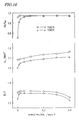
- FIG. 16 is a graph showing how the magnetic properties changed with the mass fraction of Zr in two situations where the sintering temperatures were 1,060 °C and 1,080 °C, respectively.
- the abscissa represents the Zr mass fraction
- the ordinate represents Hk (which is the strength of an external magnetic field when the magnetization becomes 90% of the remanence B r ), coercivity H cJ and remanence B r in this order downward.
- the Zr mass fraction is preferably adjusted to 0.3 mass% or less.
- an R-T-B based sintered magnet can be obtained with the decrease in coercivity minimized and with the remanence increased.
- a rare-earth sintered magnet according to the present invention affords a wide margin for the sintering temperature and can be manufactured constantly on an industrial basis.
- a rare-earth sintered magnet according to the present invention can be used particularly effectively in an application that exclusively needs high performance, as in various types of motors and actuators.
Landscapes
- Chemical & Material Sciences (AREA)
- Engineering & Computer Science (AREA)
- Materials Engineering (AREA)
- Mechanical Engineering (AREA)
- Metallurgy (AREA)
- Organic Chemistry (AREA)
- Crystallography & Structural Chemistry (AREA)
- Inorganic Chemistry (AREA)
- Power Engineering (AREA)
- Hard Magnetic Materials (AREA)
Claims (8)
- Gesinterter Seltenerdmagnet, dessen Hauptphase eine R2T14B-Typ Verbindungsphase beinhaltet, wobei der Magnet umfasst:27 Massen-% bis 32 Massen-% an R, das mindestens ein Seltenerdelement ist, das ausgewählt ist aus der Gruppe, bestehend aus Nd, Pr, Tb, und Dy, und das immer mindestens eines von Nd und Pr beinhaltet;60 Massen-% bis 73 Massen-% an T, das entweder Fe alleine oder eine Mischung aus Fe und Co ist;0,85 Massen-% bis 0,98 Massen-% an Q, das entweder B alleine oder eine Mischung aus B und C ist, und das auf der Basis der Anzahl der Atome in B umgewandelt wird, wenn sein prozentualer Massenanteil berechnet wird;mehr als 0 Massen-% bis 0,3 Massen-% an Zr;höchstens 2,0 Massen-% eines Additivelements M, das mindestens ein Element ist, ausgewählt aus der Gruppe, bestehend aus Al, Cu, Ga, In und Sn; undunvermeidbar darin enthaltene Verunreinigungen;wobei das Additivelement Ga beinhaltet, das 0,01 Massen-% bis 0,08 Massen-% des Magnets ausmacht.
- Gesinterter Seltenerdmagnet nach Anspruch 1, der keine akkumulierten Phasen an Q umfasst.
- Gesinterter Seltenerdmagnet nach Anspruch 1, der höchstens 0,95 Massen-% an Q umfasst.
- Gesinterter Seltenerdmagnet nach Anspruch 3, der mindestens 0,90 Massen-% an Q umfasst.
- Gesinterter Seltenerdmagnet nach einem der Ansprüche 1 bis 4, wobei der Magnet ein Flächenverhältnis Hk/HcJ von mindestens 0,9 in seiner Demagnetisierungskurve besitzt.
- Materiallegierung für einen gesinterten Seltenerdmagnet, dessen Hauptphase eine R2T14B-Typ Verbindungsphase beinhaltet, wobei die Legierung umfasst:27 Massen-% bis 32 Massen-% an R, das mindestens ein Seltenerdelement ist, das ausgewählt ist aus der Gruppe, bestehend aus Nd, Pr, Tb, und Dy, und das immer mindestens eines von Nd und Pr beinhaltet;60 Massen-% bis 73 Massen-% an T, das entweder Fe alleine oder eine Mischung aus Fe und Co ist;0,85 Massen-% bis 0,98 Massen-% an Q, das entweder B alleine oder eine Mischung aus B und C ist;mehr als 0 Massen-% bis 0,3 Massen-% an Zr;höchstens 2,0 Massen-% eines Additivelements M, das mindestens ein Element ist, ausgewählt aus der Gruppe, bestehend aus Al, Cu, Ga, In und Sn; undunvermeidbar darin enthaltene Verunreinigungen;wobei das Additivelement Ga beinhaltet, das 0,01 Massen-% bis 0,08 Massen-% der Legierung ausmacht.
- Seltenerdlegierung nach Anspruch 6, die keine akkumulierten Phasen an Q umfasst.
- Seltenerdlegierung nach Anspruch 6, die höchstens 0,95 Massen-% an Q umfasst.
Applications Claiming Priority (2)
| Application Number | Priority Date | Filing Date | Title |
|---|---|---|---|
| JP2003292194 | 2003-08-12 | ||
| PCT/JP2004/011743 WO2005015580A1 (ja) | 2003-08-12 | 2004-08-10 | R-t-b系焼結磁石および希土類合金 |
Publications (3)
| Publication Number | Publication Date |
|---|---|
| EP1662516A1 EP1662516A1 (de) | 2006-05-31 |
| EP1662516A4 EP1662516A4 (de) | 2009-12-09 |
| EP1662516B1 true EP1662516B1 (de) | 2014-12-31 |
Family
ID=34131705
Family Applications (1)
| Application Number | Title | Priority Date | Filing Date |
|---|---|---|---|
| EP04771704.6A Active EP1662516B1 (de) | 2003-08-12 | 2004-08-10 | Gesinterter r-t-b-magnet und seltenerdlegierung |
Country Status (5)
| Country | Link |
|---|---|
| US (1) | US7534311B2 (de) |
| EP (1) | EP1662516B1 (de) |
| JP (1) | JP4605013B2 (de) |
| CN (1) | CN100545959C (de) |
| WO (1) | WO2005015580A1 (de) |
Families Citing this family (21)
| Publication number | Priority date | Publication date | Assignee | Title |
|---|---|---|---|---|
| JP4766452B2 (ja) * | 2005-03-16 | 2011-09-07 | Tdk株式会社 | 希土類永久磁石 |
| JP4766453B2 (ja) * | 2005-03-16 | 2011-09-07 | Tdk株式会社 | 希土類永久磁石 |
| WO2008062757A1 (fr) * | 2006-11-21 | 2008-05-29 | Ulvac, Inc. | Procédé de production d'un objet orienté, d'un objet moulé, et d'un objet fritté et procédé de production d'un aimant permanent |
| JP5153643B2 (ja) * | 2007-06-29 | 2013-02-27 | Tdk株式会社 | 希土類磁石 |
| CN101560628B (zh) * | 2008-04-17 | 2012-07-11 | 北京有色金属研究总院 | 一种稀土铁合金及其制备工艺 |
| US20110074530A1 (en) * | 2009-09-30 | 2011-03-31 | General Electric Company | Mixed rare-earth permanent magnet and method of fabrication |
| JP5572673B2 (ja) | 2011-07-08 | 2014-08-13 | 昭和電工株式会社 | R−t−b系希土類焼結磁石用合金、r−t−b系希土類焼結磁石用合金の製造方法、r−t−b系希土類焼結磁石用合金材料、r−t−b系希土類焼結磁石、r−t−b系希土類焼結磁石の製造方法およびモーター |
| JP6201446B2 (ja) * | 2012-06-22 | 2017-09-27 | Tdk株式会社 | 焼結磁石 |
| CN103887028B (zh) | 2012-12-24 | 2017-07-28 | 北京中科三环高技术股份有限公司 | 一种烧结钕铁硼磁体及其制造方法 |
| JP6238444B2 (ja) * | 2013-01-07 | 2017-11-29 | 昭和電工株式会社 | R−t−b系希土類焼結磁石、r−t−b系希土類焼結磁石用合金およびその製造方法 |
| CN105723480B (zh) | 2013-06-17 | 2018-07-17 | 城市矿业科技有限责任公司 | 磁铁再生以产生磁性性能改善或恢复的Nd-Fe-B磁铁 |
| US10256015B2 (en) * | 2013-08-09 | 2019-04-09 | Tdk Corporation | R-t-b based sintered magnet and rotating machine |
| JP6229938B2 (ja) * | 2013-11-26 | 2017-11-15 | 日立金属株式会社 | R−t−b系焼結磁石 |
| KR101543111B1 (ko) * | 2013-12-17 | 2015-08-10 | 현대자동차주식회사 | NdFeB 영구자석 및 그 제조방법 |
| US9336932B1 (en) | 2014-08-15 | 2016-05-10 | Urban Mining Company | Grain boundary engineering |
| JP6358085B2 (ja) * | 2014-12-26 | 2018-07-18 | トヨタ自動車株式会社 | 希土類磁石の磁気性能の特定方法 |
| US10428408B2 (en) * | 2015-03-13 | 2019-10-01 | Tdk Corporation | R-T-B-based rare earth sintered magnet and alloy for R-T-B-based rare earth sintered magnet |
| JP6672753B2 (ja) * | 2015-03-13 | 2020-03-25 | Tdk株式会社 | R−t−b系希土類焼結磁石及びr−t−b系希土類焼結磁石用合金 |
| CN105513737A (zh) * | 2016-01-21 | 2016-04-20 | 烟台首钢磁性材料股份有限公司 | 一种不含重稀土元素烧结钕铁硼磁体的制备方法 |
| CN110942878B (zh) * | 2019-12-24 | 2021-03-26 | 厦门钨业股份有限公司 | 一种r-t-b系永磁材料及其制备方法和应用 |
| CN113066625B (zh) * | 2021-03-26 | 2023-04-11 | 福建省长汀金龙稀土有限公司 | 一种r-t-b系永磁材料及其制备方法和应用 |
Family Cites Families (33)
| Publication number | Priority date | Publication date | Assignee | Title |
|---|---|---|---|---|
| CA1316375C (en) | 1982-08-21 | 1993-04-20 | Masato Sagawa | Magnetic materials and permanent magnets |
| US4792368A (en) | 1982-08-21 | 1988-12-20 | Sumitomo Special Metals Co., Ltd. | Magnetic materials and permanent magnets |
| JPH068488B2 (ja) | 1985-06-21 | 1994-02-02 | 住友特殊金属株式会社 | 永久磁石合金 |
| EP0248981B1 (de) | 1986-06-12 | 1993-07-07 | Kabushiki Kaisha Toshiba | Dauermagnet und Dauermagnetlegierung |
| US5223047A (en) | 1986-07-23 | 1993-06-29 | Hitachi Metals, Ltd. | Permanent magnet with good thermal stability |
| EP0411571B1 (de) * | 1989-07-31 | 1994-06-01 | Mitsubishi Materials Corporation | Seltenerdpulver für Dauermagnet, Herstellungsverfahren und Verbundmagnet |
| JP2904571B2 (ja) | 1990-10-29 | 1999-06-14 | 信越化学工業株式会社 | 希土類異方性焼結永久磁石の製造方法 |
| US5405455A (en) * | 1991-06-04 | 1995-04-11 | Shin-Etsu Chemical Co. Ltd. | Rare earth-based permanent magnet |
| JPH05258928A (ja) * | 1992-03-10 | 1993-10-08 | Hitachi Metals Ltd | 永久磁石および永久磁石粉末および製造方法 |
| JP3086334B2 (ja) * | 1992-06-12 | 2000-09-11 | 住友特殊金属株式会社 | 永久磁石用異方性希土類合金粉末 |
| US5314548A (en) | 1992-06-22 | 1994-05-24 | General Motors Corporation | Fine grained anisotropic powder from melt-spun ribbons |
| JP3080275B2 (ja) | 1992-09-18 | 2000-08-21 | 日立金属株式会社 | 耐食性および耐熱性に優れたR−Fe−Co−Al−Nb−Ga−B系焼結磁石及びその製造方法 |
| US5472525A (en) | 1993-01-29 | 1995-12-05 | Hitachi Metals, Ltd. | Nd-Fe-B system permanent magnet |
| JP3296507B2 (ja) | 1993-02-02 | 2002-07-02 | 日立金属株式会社 | 希土類永久磁石 |
| JP3368294B2 (ja) * | 1993-06-25 | 2003-01-20 | 住友特殊金属株式会社 | 永久磁石用異方性希土類合金粉末の製造方法 |
| US5858123A (en) | 1995-07-12 | 1999-01-12 | Hitachi Metals, Ltd. | Rare earth permanent magnet and method for producing the same |
| JP3255344B2 (ja) | 1996-04-17 | 2002-02-12 | 日立金属株式会社 | 焼結型永久磁石 |
| JPH10289813A (ja) | 1997-04-16 | 1998-10-27 | Hitachi Metals Ltd | 希土類磁石 |
| JP3255593B2 (ja) | 1997-09-30 | 2002-02-12 | 日立金属株式会社 | 熱安定性の良好な焼結型永久磁石の製造方法 |
| DE69911138T2 (de) | 1998-10-14 | 2004-07-22 | Hitachi Metals, Ltd. | Gesinterter R-T-B-Dauermagnet |
| JP3846835B2 (ja) | 1998-10-14 | 2006-11-15 | 株式会社Neomax | R−t−b系焼結型永久磁石 |
| KR100420851B1 (ko) * | 1999-09-09 | 2004-03-02 | 스미토모 도큐슈 긴조쿠 가부시키가이샤 | 내식성 R-Fe-B계 본드 자석, R-Fe-B계 본드 자석성형용 분말 및 그 제조 방법 |
| JP2001297907A (ja) | 2000-04-14 | 2001-10-26 | Hitachi Metals Ltd | R−t−b系焼結磁石、リング磁石およびボイスコイルモータ |
| JP3951099B2 (ja) * | 2000-06-13 | 2007-08-01 | 信越化学工業株式会社 | R−Fe−B系希土類永久磁石材料 |
| US6506265B2 (en) | 2000-06-13 | 2003-01-14 | Shin-Etsu Chemical Co., Ltd. | R-Fe-B base permanent magnet materials |
| JP2002038245A (ja) | 2000-07-27 | 2002-02-06 | Hitachi Metals Ltd | 希土類永久磁石用合金粉末および希土類永久磁石の製造方法 |
| JP4371188B2 (ja) | 2000-08-22 | 2009-11-25 | 信越化学工業株式会社 | 高比電気抵抗性希土類磁石及びその製造方法 |
| JP2002285276A (ja) | 2001-03-26 | 2002-10-03 | Hitachi Metals Ltd | R−t−b−c系焼結磁石及びその製造方法 |
| US7255751B2 (en) * | 2002-09-30 | 2007-08-14 | Tdk Corporation | Method for manufacturing R-T-B system rare earth permanent magnet |
| US7311788B2 (en) * | 2002-09-30 | 2007-12-25 | Tdk Corporation | R-T-B system rare earth permanent magnet |
| EP1562203A4 (de) * | 2003-03-12 | 2009-08-05 | Hitachi Metals Ltd | R-t-b-gesinterter magnet und prozess zu seiner herstellung |
| US7199690B2 (en) * | 2003-03-27 | 2007-04-03 | Tdk Corporation | R-T-B system rare earth permanent magnet |
| US7255752B2 (en) * | 2003-03-28 | 2007-08-14 | Tdk Corporation | Method for manufacturing R-T-B system rare earth permanent magnet |
-
2004
- 2004-08-10 CN CN200480001869.2A patent/CN100545959C/zh active Active
- 2004-08-10 WO PCT/JP2004/011743 patent/WO2005015580A1/ja active Application Filing
- 2004-08-10 JP JP2005513043A patent/JP4605013B2/ja active Active
- 2004-08-10 EP EP04771704.6A patent/EP1662516B1/de active Active
- 2004-08-10 US US10/567,502 patent/US7534311B2/en active Active
Also Published As
| Publication number | Publication date |
|---|---|
| EP1662516A4 (de) | 2009-12-09 |
| EP1662516A1 (de) | 2006-05-31 |
| US20060201585A1 (en) | 2006-09-14 |
| WO2005015580A1 (ja) | 2005-02-17 |
| CN1723511A (zh) | 2006-01-18 |
| CN100545959C (zh) | 2009-09-30 |
| JP4605013B2 (ja) | 2011-01-05 |
| US7534311B2 (en) | 2009-05-19 |
| JPWO2005015580A1 (ja) | 2006-10-05 |
Similar Documents
| Publication | Publication Date | Title |
|---|---|---|
| EP1662516B1 (de) | Gesinterter r-t-b-magnet und seltenerdlegierung | |
| JP4470884B2 (ja) | R−t−b系焼結磁石およびその製造方法 | |
| EP2388350B1 (de) | Verfahren zur herstellung eines gesinterten r-t-b-magneten | |
| US7520941B2 (en) | Functionally graded rare earth permanent magnet | |
| US4975129A (en) | Permanent magnet | |
| EP1780736B1 (de) | R-T-B-Legierung, Verfahren zur Herstellung von Flocken der R-T-B-Legierung, feines Pulver für R-T-B- Seltenerd-Dauermagnete und R-T-B Seltenerd-Dauermagnete | |
| EP1860668B1 (de) | R-t-b-basierter, gesinterter magnet | |
| EP0134304B1 (de) | Permanentmagnete | |
| EP2500915B1 (de) | R-T-B gesinterter Seltenerdmagnet | |
| US8361242B2 (en) | Powders for rare earth magnets, rare earth magnets and methods for manufacturing the same | |
| EP0177371B1 (de) | Verfahren zur Herstellung eines Permanentmagneten | |
| US6527874B2 (en) | Rare earth magnet and method for making same | |
| EP3128521B1 (de) | W-haltiger r-fe-b-cu-sintermagnet und abschrecklegierung | |
| US8182618B2 (en) | Rare earth sintered magnet and method for producing same | |
| EP1818949A2 (de) | Gemischter permanenter Magnet aus seltenen Erden und mit hoher Koerzitivkraft | |
| JP4821128B2 (ja) | R−Fe−B系希土類永久磁石 | |
| US20070240790A1 (en) | Rare-earth sintered magnet and method for producing the same | |
| JP4895027B2 (ja) | R−t−b系焼結磁石及びr−t−b系焼結磁石の製造方法 | |
| JP2741508B2 (ja) | 磁気異方性焼結磁石とその製造方法 | |
| JP3298220B2 (ja) | 希土類―Fe―Nb―Ga―Al―B系焼結磁石 | |
| JP3422490B1 (ja) | 希土類永久磁石 | |
| JP3298221B2 (ja) | 希土類―Fe―V―Ga―Al―B系焼結磁石 | |
| CN114730652A (zh) | R-Fe-B系烧结磁体 |
Legal Events
| Date | Code | Title | Description |
|---|---|---|---|
| PUAI | Public reference made under article 153(3) epc to a published international application that has entered the european phase |
Free format text: ORIGINAL CODE: 0009012 |
|
| 17P | Request for examination filed |
Effective date: 20060301 |
|
| AK | Designated contracting states |
Kind code of ref document: A1 Designated state(s): DE NL |
|
| DAX | Request for extension of the european patent (deleted) | ||
| RBV | Designated contracting states (corrected) |
Designated state(s): DE NL |
|
| RAP1 | Party data changed (applicant data changed or rights of an application transferred) |
Owner name: HITACHI METALS, LTD. |
|
| A4 | Supplementary search report drawn up and despatched |
Effective date: 20091110 |
|
| RIC1 | Information provided on ipc code assigned before grant |
Ipc: H01F 1/058 20060101ALI20091104BHEP Ipc: H01F 1/057 20060101ALI20091104BHEP Ipc: C22C 38/00 20060101ALI20091104BHEP Ipc: H01F 1/08 20060101AFI20050223BHEP Ipc: H01F 1/04 20060101ALI20091104BHEP |
|
| 17Q | First examination report despatched |
Effective date: 20100413 |
|
| GRAP | Despatch of communication of intention to grant a patent |
Free format text: ORIGINAL CODE: EPIDOSNIGR1 |
|
| INTG | Intention to grant announced |
Effective date: 20140725 |
|
| GRAS | Grant fee paid |
Free format text: ORIGINAL CODE: EPIDOSNIGR3 |
|
| GRAA | (expected) grant |
Free format text: ORIGINAL CODE: 0009210 |
|
| AK | Designated contracting states |
Kind code of ref document: B1 Designated state(s): DE NL |
|
| REG | Reference to a national code |
Ref country code: NL Ref legal event code: T3 |
|
| REG | Reference to a national code |
Ref country code: DE Ref legal event code: R096 Ref document number: 602004046439 Country of ref document: DE Effective date: 20150219 |
|
| REG | Reference to a national code |
Ref country code: DE Ref legal event code: R097 Ref document number: 602004046439 Country of ref document: DE |
|
| PLBE | No opposition filed within time limit |
Free format text: ORIGINAL CODE: 0009261 |
|
| STAA | Information on the status of an ep patent application or granted ep patent |
Free format text: STATUS: NO OPPOSITION FILED WITHIN TIME LIMIT |
|
| 26N | No opposition filed |
Effective date: 20151001 |
|
| PGFP | Annual fee paid to national office [announced via postgrant information from national office to epo] |
Ref country code: NL Payment date: 20230718 Year of fee payment: 20 |
|
| REG | Reference to a national code |
Ref country code: NL Ref legal event code: HC Owner name: PROTERIAL, LTD.; JP Free format text: DETAILS ASSIGNMENT: CHANGE OF OWNER(S), CHANGE OF OWNER(S) NAME; FORMER OWNER NAME: HITACHI METALS, LTD. Effective date: 20231003 |
|
| PGFP | Annual fee paid to national office [announced via postgrant information from national office to epo] |
Ref country code: DE Payment date: 20230627 Year of fee payment: 20 |
|
| REG | Reference to a national code |
Ref country code: DE Ref legal event code: R081 Ref document number: 602004046439 Country of ref document: DE Owner name: HITACHI, LTD., JP Free format text: FORMER OWNER: HITACHI METALS, LTD., TOKYO, JP |