EP2500915B1 - R-T-B gesinterter Seltenerdmagnet - Google Patents
R-T-B gesinterter Seltenerdmagnet Download PDFInfo
- Publication number
- EP2500915B1 EP2500915B1 EP12158694.5A EP12158694A EP2500915B1 EP 2500915 B1 EP2500915 B1 EP 2500915B1 EP 12158694 A EP12158694 A EP 12158694A EP 2500915 B1 EP2500915 B1 EP 2500915B1
- Authority
- EP
- European Patent Office
- Prior art keywords
- rare earth
- sintered magnet
- earth sintered
- grain boundary
- based compound
- Prior art date
- Legal status (The legal status is an assumption and is not a legal conclusion. Google has not performed a legal analysis and makes no representation as to the accuracy of the status listed.)
- Active
Links
Images

Classifications
-
- H—ELECTRICITY
- H01—ELECTRIC ELEMENTS
- H01F—MAGNETS; INDUCTANCES; TRANSFORMERS; SELECTION OF MATERIALS FOR THEIR MAGNETIC PROPERTIES
- H01F1/00—Magnets or magnetic bodies characterised by the magnetic materials therefor; Selection of materials for their magnetic properties
- H01F1/01—Magnets or magnetic bodies characterised by the magnetic materials therefor; Selection of materials for their magnetic properties of inorganic materials
- H01F1/03—Magnets or magnetic bodies characterised by the magnetic materials therefor; Selection of materials for their magnetic properties of inorganic materials characterised by their coercivity
- H01F1/032—Magnets or magnetic bodies characterised by the magnetic materials therefor; Selection of materials for their magnetic properties of inorganic materials characterised by their coercivity of hard-magnetic materials
- H01F1/04—Magnets or magnetic bodies characterised by the magnetic materials therefor; Selection of materials for their magnetic properties of inorganic materials characterised by their coercivity of hard-magnetic materials metals or alloys
- H01F1/047—Alloys characterised by their composition
- H01F1/053—Alloys characterised by their composition containing rare earth metals
- H01F1/055—Alloys characterised by their composition containing rare earth metals and magnetic transition metals, e.g. SmCo5
- H01F1/057—Alloys characterised by their composition containing rare earth metals and magnetic transition metals, e.g. SmCo5 and IIIa elements, e.g. Nd2Fe14B
- H01F1/0571—Alloys characterised by their composition containing rare earth metals and magnetic transition metals, e.g. SmCo5 and IIIa elements, e.g. Nd2Fe14B in the form of particles, e.g. rapid quenched powders or ribbon flakes
- H01F1/0575—Alloys characterised by their composition containing rare earth metals and magnetic transition metals, e.g. SmCo5 and IIIa elements, e.g. Nd2Fe14B in the form of particles, e.g. rapid quenched powders or ribbon flakes pressed, sintered or bonded together
- H01F1/0577—Alloys characterised by their composition containing rare earth metals and magnetic transition metals, e.g. SmCo5 and IIIa elements, e.g. Nd2Fe14B in the form of particles, e.g. rapid quenched powders or ribbon flakes pressed, sintered or bonded together sintered
-
- C—CHEMISTRY; METALLURGY
- C22—METALLURGY; FERROUS OR NON-FERROUS ALLOYS; TREATMENT OF ALLOYS OR NON-FERROUS METALS
- C22C—ALLOYS
- C22C28/00—Alloys based on a metal not provided for in groups C22C5/00 - C22C27/00
-
- C—CHEMISTRY; METALLURGY
- C22—METALLURGY; FERROUS OR NON-FERROUS ALLOYS; TREATMENT OF ALLOYS OR NON-FERROUS METALS
- C22C—ALLOYS
- C22C33/00—Making ferrous alloys
- C22C33/02—Making ferrous alloys by powder metallurgy
- C22C33/0257—Making ferrous alloys by powder metallurgy characterised by the range of the alloying elements
- C22C33/0278—Making ferrous alloys by powder metallurgy characterised by the range of the alloying elements with at least one alloying element having a minimum content above 5%
-
- C—CHEMISTRY; METALLURGY
- C22—METALLURGY; FERROUS OR NON-FERROUS ALLOYS; TREATMENT OF ALLOYS OR NON-FERROUS METALS
- C22C—ALLOYS
- C22C38/00—Ferrous alloys, e.g. steel alloys
- C22C38/005—Ferrous alloys, e.g. steel alloys containing rare earths, i.e. Sc, Y, Lanthanides
-
- C—CHEMISTRY; METALLURGY
- C22—METALLURGY; FERROUS OR NON-FERROUS ALLOYS; TREATMENT OF ALLOYS OR NON-FERROUS METALS
- C22C—ALLOYS
- C22C38/00—Ferrous alloys, e.g. steel alloys
- C22C38/06—Ferrous alloys, e.g. steel alloys containing aluminium
-
- C—CHEMISTRY; METALLURGY
- C22—METALLURGY; FERROUS OR NON-FERROUS ALLOYS; TREATMENT OF ALLOYS OR NON-FERROUS METALS
- C22C—ALLOYS
- C22C38/00—Ferrous alloys, e.g. steel alloys
- C22C38/10—Ferrous alloys, e.g. steel alloys containing cobalt
-
- C—CHEMISTRY; METALLURGY
- C22—METALLURGY; FERROUS OR NON-FERROUS ALLOYS; TREATMENT OF ALLOYS OR NON-FERROUS METALS
- C22C—ALLOYS
- C22C38/00—Ferrous alloys, e.g. steel alloys
- C22C38/16—Ferrous alloys, e.g. steel alloys containing copper
-
- B—PERFORMING OPERATIONS; TRANSPORTING
- B22—CASTING; POWDER METALLURGY
- B22F—WORKING METALLIC POWDER; MANUFACTURE OF ARTICLES FROM METALLIC POWDER; MAKING METALLIC POWDER; APPARATUS OR DEVICES SPECIALLY ADAPTED FOR METALLIC POWDER
- B22F2201/00—Treatment under specific atmosphere
- B22F2201/20—Use of vacuum
Definitions
- the present invention relates to an R-T-B rare earth sintered magnet.
- R-T-B rare earth sintered magnets are used in various types of motors, such as HDD voice coil motors, and in generators, because of their high magnetic properties.
- motors such as HDD voice coil motors
- generators because of their high magnetic properties.
- demand is rapidly rising for hybrid vehicles and wind power generators.
- greater performance is also being sought for motors and generators, leading to demands for development of R-T-B rare earth sintered magnets with superior magnetic properties.
- R-T-B rare earth sintered magnets used in hybrid vehicles and for wind power generation are employed in environments with a large range of temperature variation. For this reason, measures must be taken against irreversible thermal demagnetization in order to avoid impairment of the magnetic properties with prolonged use in such environments.
- R-T-B rare earth sintered magnets therefore, it is essential to improve the coercive force, which is an index of resistance to demagnetization.
- a different method proposed for increasing the coercive force is to inhibit coarsening of the crystal grains in the main phase or to control the Cu content at the grain boundaries, as described in Japanese Patent No. 3921399 , for example.
- R-T-B rare earth sintered magnets because the coercive force of conventional R-T-B rare earth sintered magnets has been insufficient, it has been necessary to attempt micronization of the crystal grain size and modification of the grain boundary depending on the element added, or to increase the amount of heavy rare earth element used to increase the coercive force.
- R-T-B rare earth sintered magnets used in hybrid vehicles and the like are used in environments with high temperature and large temperature change, and therefore high coercive force must be maintained, making it difficult to reduce the amount of heavy rare earth element used.
- the present invention has been accomplished in light of this situation, and its object is to provide an R-T-B rare earth sintered magnet having sufficiently high coercive force without increasing the amount of heavy rare earth element used.
- the present inventors diligently studied the effects of heat treatment conditions for R-T-B rare earth sintered magnets on the structures of sintered materials, attempting to improve the magnetic properties by controlling the sintered material structures. As a result, it was found that by adjusting the heat treatment conditions for a sintered material comprising prescribed elements, a specific compound is deposited which comprises R L , T and M 1 as constituent elements, and the aforementioned problems were thereby solved.
- the invention provides in claim 1 an R-T-B rare earth sintered magnet comprising R 2 T 14 B-containing crystal grains as the main phase, and having an R L -T-M 1 based compound at the grain boundary triple points, wherein R represents a rare earth element, T represents at least one type of element selected from among Fe, Co and Cu, B represents boron, R L represents a light rare earth element, and M 1 represents aluminum (Al).
- the coercive force can be sufficiently increased. While the reason for the increased coercive force is not fully understood, it is believed to be due to the fact that the compound comprising Fe or Co as a constituent element is soft magnetic, while the R L -T-M 1 based compound is not magnetic.
- the R L -T-M 1 based compound has a light rare earth element (R L ) as the constituent element, another possible factor is that when the R-T-B rare earth sintered magnet includes a heavy rare earth element, the ratio of the heavy rare earth element with respect to the light rare earth element in the R-rich phase produced at the grain boundary is relatively increased.
- the R-T-B rare earth sintered magnet of the invention includes plate crystals comprising an R L -T-M 1 based compound at the grain boundary triple points. Including such plate crystals can increase the strength of the R-T-B rare earth sintered magnet.
- the plate crystals comprise an R L -T-M 1 based compound as the major component.
- the ratio of the area of each of the plate crystals comprising the R L -T-M 1 based compound with respect to the area of the grain boundary triple points, based on a cross-section, is 0.01-0.22.
- the atomic ratio of the constituent elements in the R L -T-M 1 based compound in the R-T-B rare earth sintered magnet of the invention preferably satisfies inequalities (1) and (2). If an R L -T-M 1 based compound having the constituent elements in this atomic ratio is present, it will be possible to further increase the coercive force of the R-T-B rare earth sintered magnet. T > R L T > M 1
- an R-T-B rare earth sintered magnet having sufficiently high coercive force without increasing the amount of heavy rare earth element used.
- Fig. 1 is a TEM photograph (80,000x) showing the cross-sectional structure of an R-T-B rare earth sintered magnet according to this embodiment.
- the R-T-B rare earth sintered magnet 100 of this embodiment comprises a main phase 10 containing an intermetallic compound made of R 2 T 14 B, and at the grain boundary triple points, plate crystals 12 comprising an R L -T-M 1 based compound and an R-rich phase 14.
- the main phase 10 is the major crystal grain in the R-T-B rare earth sintered magnet 100.
- the constituent component of the crystal grain is the main component in the R-T-B rare earth sintered magnet 100.
- the volume ratio of the main phase 10 with respect to the entire R-T-B rare earth sintered magnet 100 will generally be at least 90%.
- the intermetallic compound in the main phase 10 is a compound composed of R 2 T 14 B.
- R 2 T 14 B represents a rare earth element
- T represents at least one element selected from among Fe, Co and Cu
- B represents boron.
- R may be a light rare earth element (R L ) or a heavy rare earth element (R H ), or it may be a combination of the two.
- rare earth element refers to scandium (Sc) and yttrium (Y), belonging to Group 3, and the lanthanoid elements, of the long Periodic Table.
- the lanthanoid elements include lanthanum (La), cerium (Ce), praseodymium (Pr), neodymium (Nd), promethium (Pm), samarium (Sm), europium (Eu), gadolinium (Gd), terbium (Tb), dysprosium (Dy), holmium (Ho), erbium (Er), thulium (Tm), ytterbium (Yb) and lutetium (Lu).
- Rare earth elements can be classified as light rare earth elements and heavy rare earth elements.
- “heavy rare earth elements” refers to Gd, Tb, Dy, Ho, Er, Tm, Yb and Lu
- “light rare earth elements” refers to Sc, Y, La, Ce, Pr, Nd, Pm, Sm and Eu.
- R 2 T 14 B in the main phase 10 preferably R is a light rare earth element and more preferably at least one element selected from among Nd, Pr, Sm and Pm, B is present at 0.5-4.5 wt%, with the remainder consisting of T and unavoidable impurities.
- the compound Nd 2 Fe 14 B may be mentioned as a specific composition.
- the main phase 10 may also contain other elements as necessary, such as Ni, Mn, Al, Nb, Zr, Ti, W, Mo, V, Ga, Zn and Si.
- the heavy rare earth element preferably includes at least one element selected from among Gd, Dy, Tb and Ho.
- the plate crystals 12 comprise an R L- T-M 1 based compound.
- R L represents a light rare earth element
- T represents at least one element selected from among Fe, Co and Cu
- M 1 represents at least one element selected from among Al, Zn and Ga.
- a portion of the T may be replaced with Ni.
- the atomic ratio of the constituent elements in the R L -T-M 1 based compound preferably satisfies inequalities (1) and (2).
- the content of T in the plate crystals 12 is preferably 40-70 atomic percent and more preferably 45-65 atomic percent, based on the total content for all of the elements R L , T and M 1 .
- the content of R L in the plate crystals 12 is preferably 20-35 atomic percent and more preferably 23-33 atomic percent, based on the total content for all of the elements R L , T and M 1 .
- the content of M 1 in the plate crystals 12 is preferably 1-28 atomic percent and more preferably 2-25 atomic percent, based on the total content for all of the elements R L , T and M 1 . These element contents will allow an R-T-B rare earth sintered magnet 100 to be obtained with even higher coercive force.
- M 1 preferably includes Al.
- the plate crystals 12 may contain a small amount of at least one type of element selected from among Ag and Au, in addition to R L , T and M 1 .
- the plate crystals 12 may be present not only at the grain boundary triple points of the R-T-B rare earth sintered magnet 100, but also at the grain boundaries between particles.
- An R-rich phase 14 may also be present with the plate crystals 12 at the grain boundary triple points.
- Each plate crystal 12 has a short axis length of preferably 20-500 nm and a long axis length of preferably 0.4-2 ⁇ m, in a cross-section of the R-T-B rare earth sintered magnet 100.
- the area ratio of one plate crystal 12 at a grain boundary triple point, in a cross-section of the R-T-B rare earth sintered magnet 100 is preferably 0.01-0.22 and more preferably 0.03-0.18, from the viewpoint of further increasing the coercive force of the R-T-B rare earth sintered magnet 100.
- This area ratio can be calculated by observing a cross-section of the R-T-B rare earth sintered magnet 100 using TEM, and determining the area of the plate crystal 12 and the grain boundary triple point of the observed image.
- the R-rich phase 14 has a higher rare earth element content than the main phase 10, and for example, it may be a eutectic crystal of ⁇ Nd, ⁇ Nd and Nd 5 Fe 17 .
- the rare earth element content in the R-rich phase 14 may be 70-95 atomic percent, for example. If the plate crystals 12 and the R-rich phase 14 are copresent at a grain boundary triple point, it is possible to reduce the atomic ratio of the light rare earth element with respect to the heavy rare earth element (R L /R H ) in the R-rich phase 14. This will allow an R-T-B rare earth sintered magnet 100 to be obtained with even higher coercive force.
- the R L /R H (atomic ratio) in the R-rich phase 14 is preferably no greater than 200 and more preferably no greater than 70.
- the R-T-B rare earth sintered magnet 100 of this embodiment has sufficiently excellent coercive force, it can be suitably applied in a motor or a generator to be used in a hybrid vehicle or for wind power generation. A high coercive force can also be maintained, compared to a conventional R-T-B rare earth sintered magnet 100, even if the heavy rare earth element content is reduced. This allows the amount of expensive heavy rare earth elements used to be reduced, to lower production costs for the R-T-B rare earth sintered magnet 100.
- a preferred composition for the R-T-B rare earth sintered magnet 100 is shown below.
- the composition can be evaluated by quantitative analysis using an EDX (energy dispersive X-ray) detector.
- M 2 represents at least one element selected from among Si, Sc, Ti, V, Mo, In, Sn, Bi, Ir, Zr, Hf, Nb and W.
- T includes Fe and Co as essential elements, with a Co content of 0.05-10.00 wt%, and the total content of Ni and Mn is preferably no greater than 0.2 wt%.
- the production method comprises a preparation step, in which a starting alloy is prepared, a grinding step in which the starting alloy is ground to obtain a fine starting powder, a molding step in which the fine starting powder is molded to obtain a compact, a sintering step in which the compact is fired to obtain a sintered material, and an aging treatment step in which the sintered material is subjected to aging treatment.
- a starting alloy comprising each element in the R-T-B rare earth sintered magnet 100.
- the starting metals including the prescribed elements are prepared and used for strip casting or the like.
- a starting alloy can be prepared in this manner.
- the starting metals may be, for example, rare earth metals, rare earth alloys, pure iron, ferroboron or alloys thereof. These are used to produce a starting alloy that will yield the desired composition for the rare earth magnet. Multiple alloys with different compositions may also be prepared as the starting alloy.
- the grinding step is a step in which the starting alloy obtained in the preparation step is ground to obtain a fine starting powder.
- This step is preferably carried out in two stages, with a coarse grinding step and a fine grinding step.
- the coarse grinding step may be carried out in an inert gas atmosphere using, for example, a stamp mill, jaw crusher, Braun mill or the like. Hydrogen absorbed grinding may also be carried out after the hydrogen has been absorbed.
- the starting alloy is ground to a particle size of between about several hundred ⁇ m and several mm.
- the powder (ground product) obtained in the coarse grinding step is subjected to fine grinding, to prepare a fine starting powder with a mean particle size (volume-based cumulative particle size distribution of 50%: D50) of 3-10 ⁇ m.
- the fine grinding may be carried out using a jet mill, for example.
- the grinding of the starting alloy does not necessarily need to be carried out in two stages with a coarse grinding and fine grinding step, and instead the fine grinding step may be carried out from the start. When different types of starting alloys are prepared, they may be separately ground and then combined.
- the molding step is a step in which the fine starting powder is molded in a magnetic field to prepare a compact. Specifically, after the fine starting powder has been packed into the die situated in an electromagnet, a magnetic field is applied by the electromagnet in a low-oxygen atmosphere (oxygen concentration: ⁇ 50 ppm) to orient the crystal axes of the fine starting powder while molding the fine starting powder by compression. Molding of the magnetic field may be carried out, for example, at a pressure of 70-150 MPa in an oriented magnetic field of 1-2T.
- the sintering step is a step in which the compact is fired to obtain a sintered material.
- the compact obtained by molding in the magnetic field may be fired in a vacuum or an inert gas atmosphere to obtain a sintered material.
- the firing conditions are preferably set as appropriate depending on conditions including the composition, the grinding method and the particle size, and for example, heating may be performed at 1000-1100°C for 1-5 hours, under a reduced pressure atmosphere of no higher than 1 ⁇ 10 -2 Pa.
- the aging treatment step is a step in which the sintered material is subjected to heat treatment to obtain an R-T-B rare earth sintered magnet 100.
- heat treatment In order to obtain an R-T-B rare earth sintered magnet with plate crystals 12 at the grain boundary triple points, as in the R-T-B rare earth sintered magnet 100, heat treatment must be performed at 650-800°C for 3 hours or longer. By carrying out prolonged heat treatment in this temperature range, it is possible to produce plate crystals 12 containing an R L -T-M 1 based compound at the grain boundary triple points of the sintered material. From the viewpoint of even more reliably producing the plate crystals 12, the heating time in the temperature range of 650-800°C is preferably 5 hours or greater, more preferably 10 hours or greater and even more preferably 25 hours or greater.
- the aging treatment step is preferably conducted in two stages, from the viewpoint of further increasing the coercive force of the R-T-B rare earth sintered magnet 100.
- the heat treatment for the first stage is performed at 650-800°C for 5 hours or longer, and preferably at 700-750°C for 6 hours or longer.
- the second stage of heat treatment is conducted at 500-600°C for 0.5-10 hours and preferably at 500-550°C for 0.5-5 hours.
- phase transition will usually occur at the triple points of the sintered material during the first stage. This will allow plate crystals 12 containing an R L -T-M 1 based compound to be obtained. Strain remaining inside the sintered material can also be removed during the second stage.
- the R-T-B rare earth sintered magnet 100 obtained by the production method described above has sufficiently high coercive force due to the presence of the R L -T-M 1 based compound at the grain boundary triple points.
- the method for producing the R-T-B rare earth sintered magnet 100, incidentally, is not limited to the one described above.
- the embodiment described above is only a preferred embodiment of the invention, and the invention is in no way limited thereto.
- the R-T-B rare earth sintered magnet 100 had an R-rich phase 14 at the grain boundary triple points
- the R-T-B rare earth sintered magnet of the invention does not necessarily require an R-rich phase at the grain boundary triple points.
- it may also comprise a B-rich phase (for example, R 1.1 T 4 B 4 ) at the grain boundaries or grain boundary triple points, in addition to this phase.
- alloys A and B Two different alloys A and B were prepared by a strip casting method, with prescribed compositions.
- the alloys A and B both contained Al (aluminum) at 0.2 wt%.
- Alloy A and alloy B were combined in a weight ratio of 9:1 and subjected to coarse grinding. Specifically, hydrogen gas was absorbed into the mixed alloy at room temperature, and then heating at 650°C for 1 hour under an inert gas atmosphere, followed by dehydrogenation treatment, yielded a ground product. The obtained ground product was then cooled to room temperature under an inert gas atmosphere.
- Lauric acid amide powder was added as a grinding aid at 10 wt% to the ground product, and a Nauta mixer was used for mixing under an inert atmosphere for 30 minutes. This was followed by grinding with a high-pressure nitrogen gas jet mill, to obtain a fine starting powder with a mean particle size (volume-based cumulative particle size distribution of 50%: D50) of approximately 4 ⁇ m.
- the obtained fine starting powder was molded under a low-oxygen atmosphere (argon gas atmosphere with an oxygen concentration of ⁇ 50 ppm), under conditions with an oriented magnetic field of 1.5T and a molding pressure of approximately 118 MPa, to obtain a compact.
- argon gas atmosphere with an oxygen concentration of ⁇ 50 ppm argon gas atmosphere with an oxygen concentration of ⁇ 50 ppm
- the obtained compact was fired in a reduced pressure atmosphere of no greater than 1 ⁇ 10 -2 Pa, at 1060°C for 2 hours, to obtain a sintered compact.
- the sintered compact was subjected to 2-stage aging treatment under the conditions shown in Table 1. The aging treatment was conducted in argon gas at atmospheric pressure. An R-T-B rare earth sintered magnet for Example 1 was thus fabricated.
- Example 1 R-T-B Rare earth sintered magnets were fabricated in the same manner as Example 1, except for using the aging treatment conditions shown in Table 1.
- Table 1 Aging treatment conditions First stage Second stage Temperature (°C) Time (hr) Temperature (°C) Time (hr)
- Example 1 700 70 530 1
- Example 2 700 6 530 1 Comp. Ex. 1 800 1 530 1 Comp. Ex. 2 800 6 530 1 Comp. Ex. 3 700 1 530 1
- the magnetic properties of the R-T-B rare earth sintered magnets of the examples and comparative examples were measured using a BH curve tracer, and the Br (residual magnetic flux density), HcJ (coercive force) and Hk/HcJ (squareness ratio) were determined.
- the results are summarized in Table 2.
- the squareness ratio was determined by formula (1) below, using HcJ and Hk.
- the squareness ratio is an index of the magnet performance, and it represents the angularity of the second quadrant of the magnetic hysteresis loop measured using a B-H tracer.
- Hk is the external magnetic field intensity at which the ratio of magnetization to residual magnetic flux density is 90% in the second quadrant of the magnetic hysteresis loop.
- FIG. 1 is a TEM photograph (magnification: 80,000x) showing the cross-sectional structure of the R-T-B rare earth sintered magnet 100 of Example 1.
- the R-T-B rare earth sintered magnet 100 of Example 1 was confirmed to have multiple plate crystals 12 and an R-rich phase 14 formed at the grain boundary triple points surrounded by multiple R 2 T 14 B crystal grains (main phase 10).
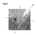
- Fig. 2 is a TEM photograph (magnification: 80,000x) showing the cross-sectional structure of the R-T-B rare earth sintered magnet 200 of Comparative Example 1.
- the R-T-B rare earth sintered magnet 200 of Comparative Example 1 had an R-rich phase 14 formed at the grain boundary triple points comprising multiple R 2 T 14 B crystal grains (main phase 10), but no plate crystals 12 had been formed.
- EDS was used for compositional analysis of the main phase 10, plate crystals 12 and R-rich phase 14 in each R-T-B rare earth sintered magnet of the examples and comparative examples.
- the results are shown in Table 3.
- the plate crystals 12 in the R-T-B rare earth sintered magnet 100 of Example 1 were confirmed to contain an Nd-T-Al-based compound composed mainly of T (Fe, Co, Cu), Al and Nd.
- the numerical values for each of the elements in Table 3 represent the atomic ratios for each element with respect to the total of R, T and M 1 .
- trace elements such as B (boron), Si (silicon), C (carbon) and oxygen (O) are also present in addition to the elements listed in Table 3, but their measurement was difficult.
- the area of the grain boundary triple point and the area of each individual plate crystal 12 in a cross-section of the R-T-B rare earth sintered magnet 100 of Example 1 were determined.
- the ratio of the area of each plate crystal 12 with respect to the area of the grain boundary triple point was also calculated.
- the areas and their ratios are summarized in Table 4.
- the areas of the triple points and plate crystals 12 were calculated using elliptical approximation.
- the ratio of the area of each individual plate crystal with respect to the area of the total triple point in a cross-section of the R-T-B rare earth sintered magnet 100 was confirmed to be in the range of 0.01-0.18. Also, the plate crystal area was confirmed to be in the range of 0.014-0.20 ⁇ m 2 .
Landscapes
- Chemical & Material Sciences (AREA)
- Engineering & Computer Science (AREA)
- Materials Engineering (AREA)
- Mechanical Engineering (AREA)
- Metallurgy (AREA)
- Organic Chemistry (AREA)
- Crystallography & Structural Chemistry (AREA)
- Inorganic Chemistry (AREA)
- Power Engineering (AREA)
- Hard Magnetic Materials (AREA)
- Powder Metallurgy (AREA)
Claims (3)
- R-T-B gesinterter Seltenerdmagnet, aufweisend:ein R2T14B enthaltendes Kristallkorn als die Hauptphase, undeine RL-T-M1 basierte Verbindung an den Korngrenzentripelpunkten,wobei die Zusammensetzung für den R-T-B gesinterten Seltenerdmagnet:wobei R ein Seltenerdelement darstellt, T mindestens ein Element darstellt, ausgewählt aus Fe, Co und Cu, B Bor darstellt, RL ein leichtes Seltenerdelement darstellt, ausgewählt aus Sc, Y, La, Cr, Pr, Nd, Pm, Sm und Eu, M1 Al darstellt, und M2 mindestens ein Element darstellt, ausgewählt aus Si, Sc, Ti, V, Mo, In, Sn, Bi, Ir, Zr, Hf, Nb und W,R: 28,50-35,00 Gew.-%M1 : 0,10-0,50 Gew.-%M2: 0,03-0,50 Gew.-%B: 0,80-1,50 Gew.-%C: 0,05-0,30 Gew.-%N: 0,02-0,15 Gew.-%O: 0,03-0,60 Gew.-%T: Rest,
wobei der R-T-B gesinterte Seltenerdmagnet flache Kristalle (plate crystals) besitzt, die die RL-T-M1 basierte Verbindung an den Korngrenzentripelpunkten umfassen, und
wobei das Verhältnis der Fläche der flachen Kristalle (plate crystals), die die RL-T-M1 basierte Verbindung umfassen, in Bezug auf die Fläche der Korngrenzentripelpunkte, basiert auf einem Querschnitt, 0,01-0,22 ist. - Der R-T-B gesinterte Seltenerdmagnet gemäß Anspruch 1, zusätzlich aufweisend R-reiche Phase, die zusammen mit den flachen Kristallen an den Korngrenzentripelpunkten vorhanden ist, wobei das Atomverhältnis R/RH in der R-reichen Phase nicht größer als 70 ist, und wobei RH Gd, Tb, Dy, Ho, Er, Tm, Yb oder Lu darstellt.
- Der R-T-B gesinterte Seltenerdmagnet gemäß einem der Ansprüche 1 oder 2, wobei das Atomverhältnis der konstituierenden Elemente in der RL-T-M1 basierten Verbindung die folgenden Ungleichungen (1) und (2) erfüllt:


Applications Claiming Priority (1)
| Application Number | Priority Date | Filing Date | Title |
|---|---|---|---|
| JP2011060523A JP5729051B2 (ja) | 2011-03-18 | 2011-03-18 | R−t−b系希土類焼結磁石 |
Publications (2)
| Publication Number | Publication Date |
|---|---|
| EP2500915A1 EP2500915A1 (de) | 2012-09-19 |
| EP2500915B1 true EP2500915B1 (de) | 2014-05-14 |
Family
ID=46000691
Family Applications (1)
| Application Number | Title | Priority Date | Filing Date |
|---|---|---|---|
| EP12158694.5A Active EP2500915B1 (de) | 2011-03-18 | 2012-03-09 | R-T-B gesinterter Seltenerdmagnet |
Country Status (4)
| Country | Link |
|---|---|
| US (1) | US20120235778A1 (de) |
| EP (1) | EP2500915B1 (de) |
| JP (1) | JP5729051B2 (de) |
| CN (1) | CN102693812B (de) |
Families Citing this family (16)
| Publication number | Priority date | Publication date | Assignee | Title |
|---|---|---|---|---|
| US9620268B2 (en) * | 2011-10-13 | 2017-04-11 | Tdk Corporation | R-T-B based alloy strip, and R-T-B based sintered magnet and method for producing same |
| DE112014003688T5 (de) * | 2013-08-09 | 2016-04-28 | Tdk Corporation | Sintermagnet auf R-T-B-Basis und Motor |
| WO2015020182A1 (ja) * | 2013-08-09 | 2015-02-12 | Tdk株式会社 | R-t-b系焼結磁石、および、モータ |
| JP6476640B2 (ja) * | 2013-08-09 | 2019-03-06 | Tdk株式会社 | R−t−b系焼結磁石 |
| JP6142792B2 (ja) | 2013-12-20 | 2017-06-07 | Tdk株式会社 | 希土類磁石 |
| JP6142793B2 (ja) * | 2013-12-20 | 2017-06-07 | Tdk株式会社 | 希土類磁石 |
| JP6142794B2 (ja) | 2013-12-20 | 2017-06-07 | Tdk株式会社 | 希土類磁石 |
| JP6784484B2 (ja) * | 2015-09-11 | 2020-11-11 | Tdk株式会社 | R−t−b系焼結磁石およびモータ |
| JP6724865B2 (ja) * | 2016-06-20 | 2020-07-15 | 信越化学工業株式会社 | R−Fe−B系焼結磁石及びその製造方法 |
| JP6614084B2 (ja) | 2016-09-26 | 2019-12-04 | 信越化学工業株式会社 | R−Fe−B系焼結磁石の製造方法 |
| JPWO2018101410A1 (ja) * | 2016-11-30 | 2019-11-07 | Tdk株式会社 | 希土類永久磁石 |
| WO2018101239A1 (ja) * | 2016-12-02 | 2018-06-07 | 信越化学工業株式会社 | R-Fe-B系焼結磁石及びその製造方法 |
| JP7379935B2 (ja) * | 2018-11-06 | 2023-11-15 | 大同特殊鋼株式会社 | RFeB系焼結磁石 |
| JP7463791B2 (ja) * | 2020-03-23 | 2024-04-09 | Tdk株式会社 | R-t-b系希土類焼結磁石およびr-t-b系希土類焼結磁石の製造方法 |
| JP7409285B2 (ja) * | 2020-10-22 | 2024-01-09 | トヨタ自動車株式会社 | 希土類磁石及びその製造方法 |
| CN114284018B (zh) * | 2021-12-27 | 2025-01-28 | 烟台正海磁性材料股份有限公司 | 钕铁硼磁体及其制备方法和应用 |
Family Cites Families (10)
| Publication number | Priority date | Publication date | Assignee | Title |
|---|---|---|---|---|
| US4601875A (en) * | 1983-05-25 | 1986-07-22 | Sumitomo Special Metals Co., Ltd. | Process for producing magnetic materials |
| CA2023924A1 (en) * | 1989-12-19 | 1991-06-20 | Earl G. Brewer | Alloying low-level additives into hot-worked nd-fe-b magnets |
| JPH06302419A (ja) * | 1993-04-13 | 1994-10-28 | Seiko Epson Corp | 希土類永久磁石およびその製造方法 |
| EP1260995B1 (de) * | 1993-11-02 | 2005-03-30 | TDK Corporation | Préparation d'un aimant permanent |
| JPH08264308A (ja) * | 1995-03-22 | 1996-10-11 | Seiko Epson Corp | 希土類磁石およびその製造方法 |
| JPH08273914A (ja) * | 1995-03-31 | 1996-10-18 | Seiko Epson Corp | 希土類磁石およびその製造方法 |
| JP3921399B2 (ja) | 2001-03-01 | 2007-05-30 | Tdk株式会社 | 焼結磁石 |
| JP2003031409A (ja) * | 2001-07-18 | 2003-01-31 | Hitachi Metals Ltd | 耐食性に優れた希土類焼結磁石 |
| US7311788B2 (en) * | 2002-09-30 | 2007-12-25 | Tdk Corporation | R-T-B system rare earth permanent magnet |
| US7314531B2 (en) * | 2003-03-28 | 2008-01-01 | Tdk Corporation | R-T-B system rare earth permanent magnet |
-
2011
- 2011-03-18 JP JP2011060523A patent/JP5729051B2/ja active Active
-
2012
- 2012-03-09 EP EP12158694.5A patent/EP2500915B1/de active Active
- 2012-03-12 US US13/417,784 patent/US20120235778A1/en not_active Abandoned
- 2012-03-19 CN CN201210073105.0A patent/CN102693812B/zh active Active
Also Published As
| Publication number | Publication date |
|---|---|
| US20120235778A1 (en) | 2012-09-20 |
| JP2012199270A (ja) | 2012-10-18 |
| JP5729051B2 (ja) | 2015-06-03 |
| CN102693812A (zh) | 2012-09-26 |
| EP2500915A1 (de) | 2012-09-19 |
| CN102693812B (zh) | 2016-08-03 |
Similar Documents
| Publication | Publication Date | Title |
|---|---|---|
| EP2500915B1 (de) | R-T-B gesinterter Seltenerdmagnet | |
| US9997284B2 (en) | Sintered magnet | |
| EP1860668B1 (de) | R-t-b-basierter, gesinterter magnet | |
| EP2172947B1 (de) | Seltenerdmagnet | |
| US12562297B2 (en) | R-T-B-based rare earth magnet particles, process for producing the R-T-B-based rare earth magnet particles, and bonded magnet | |
| EP2387044B1 (de) | Gesinterter R-T-B-Seltenerdmagnet | |
| US8012269B2 (en) | Nd-Fe-B rare earth permanent magnet material | |
| US7618497B2 (en) | R-T-B based rare earth permanent magnet and method for production thereof | |
| JP5115511B2 (ja) | 希土類磁石 | |
| EP2590180A1 (de) | R-t-b-seltenerd-permanentmagnet, motor, automobil, stromgenerator und system zur windenergieerzeugung | |
| EP1662516B1 (de) | Gesinterter r-t-b-magnet und seltenerdlegierung | |
| EP2415541A1 (de) | Legierungsmaterial für einen r-t-b-seltenerd-permanentmagneten, verfahren zur herstellung des r-t-b-seltenerd-permanentmagneten und motor | |
| US11996219B2 (en) | Magnetic material and manufacturing method thereof | |
| JP4900085B2 (ja) | 希土類磁石の製造方法 | |
| JP4076178B2 (ja) | R−t−b系希土類永久磁石 | |
| CN111710489A (zh) | R-t-b系永久磁铁 | |
| JP4821128B2 (ja) | R−Fe−B系希土類永久磁石 | |
| CN113764149A (zh) | 稀土磁铁及其制造方法 | |
| JP4702522B2 (ja) | R−t−b系焼結磁石及びその製造方法 | |
| CN113571279A (zh) | 磁体及其制造方法 | |
| EP4130301A1 (de) | Anisotroper seltenerd-sintermagnet und verfahren zum produzieren desselben | |
| JP2022093885A (ja) | 希土類磁石の製造方法 | |
| JPH05267027A (ja) | R−Fe−B系永久磁石用原料粉末の製造方法及び原料粉末調整用合金粉末 | |
| JP2886384B2 (ja) | R−Fe−B系永久磁石用原料粉末の製造方法 | |
| JP3053344B2 (ja) | 希土類磁石の製造方法 |
Legal Events
| Date | Code | Title | Description |
|---|---|---|---|
| PUAI | Public reference made under article 153(3) epc to a published international application that has entered the european phase |
Free format text: ORIGINAL CODE: 0009012 |
|
| 17P | Request for examination filed |
Effective date: 20120309 |
|
| AK | Designated contracting states |
Kind code of ref document: A1 Designated state(s): AL AT BE BG CH CY CZ DE DK EE ES FI FR GB GR HR HU IE IS IT LI LT LU LV MC MK MT NL NO PL PT RO RS SE SI SK SM TR |
|
| AX | Request for extension of the european patent |
Extension state: BA ME |
|
| RAP1 | Party data changed (applicant data changed or rights of an application transferred) |
Owner name: TDK CORPORATION |
|
| RAP1 | Party data changed (applicant data changed or rights of an application transferred) |
Owner name: TDK CORPORATION |
|
| GRAP | Despatch of communication of intention to grant a patent |
Free format text: ORIGINAL CODE: EPIDOSNIGR1 |
|
| INTG | Intention to grant announced |
Effective date: 20131115 |
|
| GRAS | Grant fee paid |
Free format text: ORIGINAL CODE: EPIDOSNIGR3 |
|
| GRAA | (expected) grant |
Free format text: ORIGINAL CODE: 0009210 |
|
| AK | Designated contracting states |
Kind code of ref document: B1 Designated state(s): AL AT BE BG CH CY CZ DE DK EE ES FI FR GB GR HR HU IE IS IT LI LT LU LV MC MK MT NL NO PL PT RO RS SE SI SK SM TR |
|
| REG | Reference to a national code |
Ref country code: GB Ref legal event code: FG4D |
|
| REG | Reference to a national code |
Ref country code: AT Ref legal event code: REF Ref document number: 668829 Country of ref document: AT Kind code of ref document: T Effective date: 20140615 |
|
| REG | Reference to a national code |
Ref country code: DE Ref legal event code: R096 Ref document number: 602012001641 Country of ref document: DE Effective date: 20140618 Ref country code: IE Ref legal event code: FG4D |
|
| REG | Reference to a national code |
Ref country code: NL Ref legal event code: VDEP Effective date: 20140514 Ref country code: AT Ref legal event code: MK05 Ref document number: 668829 Country of ref document: AT Kind code of ref document: T Effective date: 20140514 |
|
| REG | Reference to a national code |
Ref country code: LT Ref legal event code: MG4D |
|
| PG25 | Lapsed in a contracting state [announced via postgrant information from national office to epo] |
Ref country code: GR Free format text: LAPSE BECAUSE OF FAILURE TO SUBMIT A TRANSLATION OF THE DESCRIPTION OR TO PAY THE FEE WITHIN THE PRESCRIBED TIME-LIMIT Effective date: 20140815 Ref country code: IS Free format text: LAPSE BECAUSE OF FAILURE TO SUBMIT A TRANSLATION OF THE DESCRIPTION OR TO PAY THE FEE WITHIN THE PRESCRIBED TIME-LIMIT Effective date: 20140914 Ref country code: LT Free format text: LAPSE BECAUSE OF FAILURE TO SUBMIT A TRANSLATION OF THE DESCRIPTION OR TO PAY THE FEE WITHIN THE PRESCRIBED TIME-LIMIT Effective date: 20140514 Ref country code: NO Free format text: LAPSE BECAUSE OF FAILURE TO SUBMIT A TRANSLATION OF THE DESCRIPTION OR TO PAY THE FEE WITHIN THE PRESCRIBED TIME-LIMIT Effective date: 20140814 Ref country code: FI Free format text: LAPSE BECAUSE OF FAILURE TO SUBMIT A TRANSLATION OF THE DESCRIPTION OR TO PAY THE FEE WITHIN THE PRESCRIBED TIME-LIMIT Effective date: 20140514 Ref country code: CY Free format text: LAPSE BECAUSE OF FAILURE TO SUBMIT A TRANSLATION OF THE DESCRIPTION OR TO PAY THE FEE WITHIN THE PRESCRIBED TIME-LIMIT Effective date: 20140514 |
|
| PG25 | Lapsed in a contracting state [announced via postgrant information from national office to epo] |
Ref country code: SE Free format text: LAPSE BECAUSE OF FAILURE TO SUBMIT A TRANSLATION OF THE DESCRIPTION OR TO PAY THE FEE WITHIN THE PRESCRIBED TIME-LIMIT Effective date: 20140514 Ref country code: PL Free format text: LAPSE BECAUSE OF FAILURE TO SUBMIT A TRANSLATION OF THE DESCRIPTION OR TO PAY THE FEE WITHIN THE PRESCRIBED TIME-LIMIT Effective date: 20140514 Ref country code: HR Free format text: LAPSE BECAUSE OF FAILURE TO SUBMIT A TRANSLATION OF THE DESCRIPTION OR TO PAY THE FEE WITHIN THE PRESCRIBED TIME-LIMIT Effective date: 20140514 Ref country code: RS Free format text: LAPSE BECAUSE OF FAILURE TO SUBMIT A TRANSLATION OF THE DESCRIPTION OR TO PAY THE FEE WITHIN THE PRESCRIBED TIME-LIMIT Effective date: 20140514 Ref country code: ES Free format text: LAPSE BECAUSE OF FAILURE TO SUBMIT A TRANSLATION OF THE DESCRIPTION OR TO PAY THE FEE WITHIN THE PRESCRIBED TIME-LIMIT Effective date: 20140514 Ref country code: AT Free format text: LAPSE BECAUSE OF FAILURE TO SUBMIT A TRANSLATION OF THE DESCRIPTION OR TO PAY THE FEE WITHIN THE PRESCRIBED TIME-LIMIT Effective date: 20140514 Ref country code: LV Free format text: LAPSE BECAUSE OF FAILURE TO SUBMIT A TRANSLATION OF THE DESCRIPTION OR TO PAY THE FEE WITHIN THE PRESCRIBED TIME-LIMIT Effective date: 20140514 |
|
| PG25 | Lapsed in a contracting state [announced via postgrant information from national office to epo] |
Ref country code: PT Free format text: LAPSE BECAUSE OF FAILURE TO SUBMIT A TRANSLATION OF THE DESCRIPTION OR TO PAY THE FEE WITHIN THE PRESCRIBED TIME-LIMIT Effective date: 20140915 |
|
| PG25 | Lapsed in a contracting state [announced via postgrant information from national office to epo] |
Ref country code: CZ Free format text: LAPSE BECAUSE OF FAILURE TO SUBMIT A TRANSLATION OF THE DESCRIPTION OR TO PAY THE FEE WITHIN THE PRESCRIBED TIME-LIMIT Effective date: 20140514 Ref country code: SK Free format text: LAPSE BECAUSE OF FAILURE TO SUBMIT A TRANSLATION OF THE DESCRIPTION OR TO PAY THE FEE WITHIN THE PRESCRIBED TIME-LIMIT Effective date: 20140514 Ref country code: BE Free format text: LAPSE BECAUSE OF FAILURE TO SUBMIT A TRANSLATION OF THE DESCRIPTION OR TO PAY THE FEE WITHIN THE PRESCRIBED TIME-LIMIT Effective date: 20140514 Ref country code: EE Free format text: LAPSE BECAUSE OF FAILURE TO SUBMIT A TRANSLATION OF THE DESCRIPTION OR TO PAY THE FEE WITHIN THE PRESCRIBED TIME-LIMIT Effective date: 20140514 Ref country code: RO Free format text: LAPSE BECAUSE OF FAILURE TO SUBMIT A TRANSLATION OF THE DESCRIPTION OR TO PAY THE FEE WITHIN THE PRESCRIBED TIME-LIMIT Effective date: 20140514 Ref country code: DK Free format text: LAPSE BECAUSE OF FAILURE TO SUBMIT A TRANSLATION OF THE DESCRIPTION OR TO PAY THE FEE WITHIN THE PRESCRIBED TIME-LIMIT Effective date: 20140514 |
|
| REG | Reference to a national code |
Ref country code: DE Ref legal event code: R097 Ref document number: 602012001641 Country of ref document: DE |
|
| PG25 | Lapsed in a contracting state [announced via postgrant information from national office to epo] |
Ref country code: NL Free format text: LAPSE BECAUSE OF FAILURE TO SUBMIT A TRANSLATION OF THE DESCRIPTION OR TO PAY THE FEE WITHIN THE PRESCRIBED TIME-LIMIT Effective date: 20140514 |
|
| PLBE | No opposition filed within time limit |
Free format text: ORIGINAL CODE: 0009261 |
|
| STAA | Information on the status of an ep patent application or granted ep patent |
Free format text: STATUS: NO OPPOSITION FILED WITHIN TIME LIMIT |
|
| 26N | No opposition filed |
Effective date: 20150217 |
|
| PG25 | Lapsed in a contracting state [announced via postgrant information from national office to epo] |
Ref country code: IT Free format text: LAPSE BECAUSE OF FAILURE TO SUBMIT A TRANSLATION OF THE DESCRIPTION OR TO PAY THE FEE WITHIN THE PRESCRIBED TIME-LIMIT Effective date: 20140514 |
|
| REG | Reference to a national code |
Ref country code: DE Ref legal event code: R097 Ref document number: 602012001641 Country of ref document: DE Effective date: 20150217 |
|
| PG25 | Lapsed in a contracting state [announced via postgrant information from national office to epo] |
Ref country code: SI Free format text: LAPSE BECAUSE OF FAILURE TO SUBMIT A TRANSLATION OF THE DESCRIPTION OR TO PAY THE FEE WITHIN THE PRESCRIBED TIME-LIMIT Effective date: 20140514 |
|
| PG25 | Lapsed in a contracting state [announced via postgrant information from national office to epo] |
Ref country code: LU Free format text: LAPSE BECAUSE OF FAILURE TO SUBMIT A TRANSLATION OF THE DESCRIPTION OR TO PAY THE FEE WITHIN THE PRESCRIBED TIME-LIMIT Effective date: 20150309 Ref country code: MC Free format text: LAPSE BECAUSE OF FAILURE TO SUBMIT A TRANSLATION OF THE DESCRIPTION OR TO PAY THE FEE WITHIN THE PRESCRIBED TIME-LIMIT Effective date: 20140514 |
|
| REG | Reference to a national code |
Ref country code: CH Ref legal event code: PL |
|
| REG | Reference to a national code |
Ref country code: FR Ref legal event code: ST Effective date: 20151130 |
|
| REG | Reference to a national code |
Ref country code: IE Ref legal event code: MM4A |
|
| PG25 | Lapsed in a contracting state [announced via postgrant information from national office to epo] |
Ref country code: LI Free format text: LAPSE BECAUSE OF NON-PAYMENT OF DUE FEES Effective date: 20150331 Ref country code: CH Free format text: LAPSE BECAUSE OF NON-PAYMENT OF DUE FEES Effective date: 20150331 Ref country code: IE Free format text: LAPSE BECAUSE OF NON-PAYMENT OF DUE FEES Effective date: 20150309 |
|
| PG25 | Lapsed in a contracting state [announced via postgrant information from national office to epo] |
Ref country code: FR Free format text: LAPSE BECAUSE OF NON-PAYMENT OF DUE FEES Effective date: 20150331 |
|
| GBPC | Gb: european patent ceased through non-payment of renewal fee |
Effective date: 20160309 |
|
| PG25 | Lapsed in a contracting state [announced via postgrant information from national office to epo] |
Ref country code: MT Free format text: LAPSE BECAUSE OF FAILURE TO SUBMIT A TRANSLATION OF THE DESCRIPTION OR TO PAY THE FEE WITHIN THE PRESCRIBED TIME-LIMIT Effective date: 20140514 |
|
| PG25 | Lapsed in a contracting state [announced via postgrant information from national office to epo] |
Ref country code: GB Free format text: LAPSE BECAUSE OF NON-PAYMENT OF DUE FEES Effective date: 20160309 |
|
| PG25 | Lapsed in a contracting state [announced via postgrant information from national office to epo] |
Ref country code: HU Free format text: LAPSE BECAUSE OF FAILURE TO SUBMIT A TRANSLATION OF THE DESCRIPTION OR TO PAY THE FEE WITHIN THE PRESCRIBED TIME-LIMIT; INVALID AB INITIO Effective date: 20120309 Ref country code: SM Free format text: LAPSE BECAUSE OF FAILURE TO SUBMIT A TRANSLATION OF THE DESCRIPTION OR TO PAY THE FEE WITHIN THE PRESCRIBED TIME-LIMIT Effective date: 20140514 Ref country code: BG Free format text: LAPSE BECAUSE OF FAILURE TO SUBMIT A TRANSLATION OF THE DESCRIPTION OR TO PAY THE FEE WITHIN THE PRESCRIBED TIME-LIMIT Effective date: 20140514 |
|
| PG25 | Lapsed in a contracting state [announced via postgrant information from national office to epo] |
Ref country code: TR Free format text: LAPSE BECAUSE OF FAILURE TO SUBMIT A TRANSLATION OF THE DESCRIPTION OR TO PAY THE FEE WITHIN THE PRESCRIBED TIME-LIMIT Effective date: 20140514 |
|
| PG25 | Lapsed in a contracting state [announced via postgrant information from national office to epo] |
Ref country code: MK Free format text: LAPSE BECAUSE OF FAILURE TO SUBMIT A TRANSLATION OF THE DESCRIPTION OR TO PAY THE FEE WITHIN THE PRESCRIBED TIME-LIMIT Effective date: 20140514 |
|
| PG25 | Lapsed in a contracting state [announced via postgrant information from national office to epo] |
Ref country code: AL Free format text: LAPSE BECAUSE OF FAILURE TO SUBMIT A TRANSLATION OF THE DESCRIPTION OR TO PAY THE FEE WITHIN THE PRESCRIBED TIME-LIMIT Effective date: 20140514 |
|
| PGFP | Annual fee paid to national office [announced via postgrant information from national office to epo] |
Ref country code: DE Payment date: 20250128 Year of fee payment: 14 |