EP1661654B1 - Soldering iron and method of manufacturing same - Google Patents
Soldering iron and method of manufacturing same Download PDFInfo
- Publication number
- EP1661654B1 EP1661654B1 EP05257169.2A EP05257169A EP1661654B1 EP 1661654 B1 EP1661654 B1 EP 1661654B1 EP 05257169 A EP05257169 A EP 05257169A EP 1661654 B1 EP1661654 B1 EP 1661654B1
- Authority
- EP
- European Patent Office
- Prior art keywords
- cylindrical member
- heater
- insertion fit
- fit portion
- temperature sensor
- Prior art date
- Legal status (The legal status is an assumption and is not a legal conclusion. Google has not performed a legal analysis and makes no representation as to the accuracy of the status listed.)
- Expired - Lifetime
Links
Images


Classifications
-
- B—PERFORMING OPERATIONS; TRANSPORTING
- B23—MACHINE TOOLS; METAL-WORKING NOT OTHERWISE PROVIDED FOR
- B23K—SOLDERING OR UNSOLDERING; WELDING; CLADDING OR PLATING BY SOLDERING OR WELDING; CUTTING BY APPLYING HEAT LOCALLY, e.g. FLAME CUTTING; WORKING BY LASER BEAM
- B23K3/00—Tools, devices or special appurtenances for soldering, e.g. brazing, or unsoldering, not specially adapted for particular methods
- B23K3/02—Soldering irons; Bits
- B23K3/03—Soldering irons; Bits electrically heated
- B23K3/0338—Constructional features of electric soldering irons
- B23K3/0369—Couplings between the heating element housing and the bit or tip
-
- B—PERFORMING OPERATIONS; TRANSPORTING
- B23—MACHINE TOOLS; METAL-WORKING NOT OTHERWISE PROVIDED FOR
- B23K—SOLDERING OR UNSOLDERING; WELDING; CLADDING OR PLATING BY SOLDERING OR WELDING; CUTTING BY APPLYING HEAT LOCALLY, e.g. FLAME CUTTING; WORKING BY LASER BEAM
- B23K3/00—Tools, devices or special appurtenances for soldering, e.g. brazing, or unsoldering, not specially adapted for particular methods
- B23K3/02—Soldering irons; Bits
- B23K3/03—Soldering irons; Bits electrically heated
- B23K3/033—Soldering irons; Bits electrically heated comprising means for controlling or selecting the temperature or power
-
- B—PERFORMING OPERATIONS; TRANSPORTING
- B23—MACHINE TOOLS; METAL-WORKING NOT OTHERWISE PROVIDED FOR
- B23K—SOLDERING OR UNSOLDERING; WELDING; CLADDING OR PLATING BY SOLDERING OR WELDING; CUTTING BY APPLYING HEAT LOCALLY, e.g. FLAME CUTTING; WORKING BY LASER BEAM
- B23K3/00—Tools, devices or special appurtenances for soldering, e.g. brazing, or unsoldering, not specially adapted for particular methods
- B23K3/02—Soldering irons; Bits
- B23K3/03—Soldering irons; Bits electrically heated
- B23K3/0338—Constructional features of electric soldering irons
-
- B—PERFORMING OPERATIONS; TRANSPORTING
- B23—MACHINE TOOLS; METAL-WORKING NOT OTHERWISE PROVIDED FOR
- B23K—SOLDERING OR UNSOLDERING; WELDING; CLADDING OR PLATING BY SOLDERING OR WELDING; CUTTING BY APPLYING HEAT LOCALLY, e.g. FLAME CUTTING; WORKING BY LASER BEAM
- B23K3/00—Tools, devices or special appurtenances for soldering, e.g. brazing, or unsoldering, not specially adapted for particular methods
- B23K3/04—Heating appliances
- B23K3/047—Heating appliances electric
- B23K3/053—Heating appliances electric using resistance wires
-
- B—PERFORMING OPERATIONS; TRANSPORTING
- B23—MACHINE TOOLS; METAL-WORKING NOT OTHERWISE PROVIDED FOR
- B23K—SOLDERING OR UNSOLDERING; WELDING; CLADDING OR PLATING BY SOLDERING OR WELDING; CUTTING BY APPLYING HEAT LOCALLY, e.g. FLAME CUTTING; WORKING BY LASER BEAM
- B23K3/00—Tools, devices or special appurtenances for soldering, e.g. brazing, or unsoldering, not specially adapted for particular methods
- B23K3/08—Auxiliary devices therefor
-
- Y—GENERAL TAGGING OF NEW TECHNOLOGICAL DEVELOPMENTS; GENERAL TAGGING OF CROSS-SECTIONAL TECHNOLOGIES SPANNING OVER SEVERAL SECTIONS OF THE IPC; TECHNICAL SUBJECTS COVERED BY FORMER USPC CROSS-REFERENCE ART COLLECTIONS [XRACs] AND DIGESTS
- Y10—TECHNICAL SUBJECTS COVERED BY FORMER USPC
- Y10T—TECHNICAL SUBJECTS COVERED BY FORMER US CLASSIFICATION
- Y10T29/00—Metal working
- Y10T29/49—Method of mechanical manufacture
Definitions
- This invention relates to a soldering iron according to the preamble of claim 1 and a method of manufacturing the soldering iron according to claim 4.
- Soldering iron tips have been provided in which a thermally conductive material is formed in the shape of a cone with a heater being housed therein refer to Japanese Unexamined Application, First Publication No. 2004-17060 ).
- the heater generally includes a comparatively high-reststance wire wound into the shape of a coil.
- soldering irons constructed to be extremely small (hereafter, an "extremely small soldering iron") so that the soldering tip thereof can suitably reach within a very small region when performing such soldering.
- the inside of such an extremely small soldering iron is constituted similarly to an ordinary size soldering iron.
- built in the extremely small soldering iron as well is a heater formed by wire material having resistance wound into the shape of a coil.
- soldering tip itself of the aforementioned extremely small soldering iron is constituted to be very small, the spacing between adjacent portions of the coiled wire material in the heater is considerably smaller than in an ordinary size soldering iron. For that reason, there has been the problem of adjacent wires electrically shorting or breaking by contact. Moreover, increasing the spacing between adjacent turns of the coiled wire gives rise to the problem of heat being transmitted to the grip portion of the soldering iron.
- US 6 087 631 discloses a soldering iron according to the preamble of claim 1.
- the present invention was achieved in view of the above circumstances, and provides a soldering iron that is constituted to be of an extremely small size yet easy to use by suitably preventing electrical troubles including shorting, heating quickly, and suitably maintaining a temperature suitable for soldering work and a manufacturing method of the soldering iron.
- the present invention provides the following soldering iron and manufacturing method thereof.
- the soldering iron of the present invention is a soldering iron according to claim 1.
- the heater that heats the soldering tip in the soldering iron is formed into the shape of a coil and the surface of the coiled heater is covered with an insulating oxide film.
- the wire that generates heat by its resistance is insulated from electrical contact with itself by the insulating oxide film. Electrical shorting is thereby avoided even if the wire makes mutual contact, thus allowing the wire formed in a coil shape to be disposed with the spacing therebetween narrowed.
- electrical problems such as wire breakage are also easily avoided by means of the insulating oxide film.
- the spacing between the adjacent turns of the coiled wire disposed in the shape of a coil may be made still smaller. This enables the size of the heater to be constituted small, so that the soldering tip may be constituted extremely small.
- the spacing between the turns of the wire is narrowed, the amount of heating per unit volume also increases, thereby enabling prompt heating of the soldering tip.
- the size of the haater is small, the portion heated by the heater may be limited to the soldering tip.
- the material of the wire constituting the heater is a chromium iron-base metal containing aluminum.
- the insulating oxide film when an insulating oxide film that covers the above-mentioned wire is formed, the insulating oxide film may be suitably formed.
- chromium iron-base metal containing aluminum such as Kanthal wire
- high-temperature oxidation of the contained aluminum occurs, resulting in an oxide film (alumina film) being suitably formed on the surface thereof.
- the aluminum oxide (alumina) which forms the oxide film is electrically insulating. Therefore, the insulating oxide film is formed so as to suitably cover the wire, so that the aforementioned desired operational advantage may be preferably attained.
- the insertion fit recess portion includes a heater insertion fit portion provided at the proximal end side of the soldering tip and a temperature sensor insertion fit portion provided at the distal end side of the soldering tip and having an inner diameter smaller than the inner diameter of the heater insertion fit portion, and wherein a temperature sensor for measuring temperature is fittingly inserted into the temperature sensor insertion fit portion and makes contact with the inner periphery of the temperature sensor insertion fit portion.
- the temperature of a soldering tip may be desirably measured. Therefore, when the soldering tip is heated by the heater fittingly inserted into the heater insertion fit portion, electric power suitable for the heater may be supplied so that the soldering tip may be maintained at a desired temperature. Accordingly, a soldering iron may be obtained that may maintain a suitable temperature desirable for soldering when perfoming soldering work. Consequently, soldering work is easily performed.
- a cylinder with an outer diameter smaller than the inner diameter of the temperature sensor insertion fit portion is fittingly inserted in the temperature sensor insertion fit portion, and the temperature sensor is sadwiched between the outer periphery of the cylinder and the inner periphery of the temperature sensor insertion fit portion.
- the temperature sensor since the temperature sensor is fixedly held favorably and may make secure contact with the inner periphery of the temperature sensor insertion fit portion, it may desirably measure the temperature of the soldering tip. Therefore, when the soldering tip is heated by the heater titingly inserted into the heater insertion tit portion, electric power suitable for the heater may be supplied so that the soldering tip may be maintained to a desired temperature. Accordingly, a soldering iron may be obtained that may maintain a suitable temperature desirable for soldering when performing soldering work. Consequently, soldering work is easily performed.
- the method of manufacturing the soldering iron of the present invention is a manufacturing method according to claim 4.
- the wire that generates heat by its resistance is insulated from mutual electrical contact by the insulating oxide film. Electrical shorting is thereby avoided even if the adjacent turns of the wire make mutual contact, thus allowing the coiled wire to be disposed with the spacing therebetween narrowed. In addition, electrical problems such as wire breakage are also easily avoided with the insulating oxide film. Moreover, since the temperature sensor is provided abutting against the inner periphery of the insertion fit recess portion, the temperature of the soldering tip may be desirably measured.
- the spacing between the adjacent turns of the wire disposed in a coil shape may be made still smaller.
- This enables the size of the heater to be constituted small, so that the soldering tip may be constituted extremely small.
- the amount of heating per unit volume also increases, and so the soldering tip may be quickly heated.
- the portion heated with the heater may be limited to the soldering tip.
- the temperature of the soldering tip is maintained at the desired temperature by measuring temperature performed by the temperature sensor, so that a soldering iron may be obtained that may maintain a suitable temperature desirable for soldering when performing soldering work.
- soldering iron of the present invention and the manufacturing method thereof, a soldering iron that is constituted to be of an extremely small size yet easy to use by suitably preventing electrical troubles including shorting heating quickly and suitably maintaining a temperature suitable for soldering work and a manufacturing method of the soldering iron may be obtained.
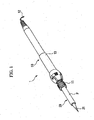
- FIG. 1 is a perspective view of the soldering iron of the present invention
- FIG. 2 is a cross-sectional perspective view of the soldering tip
- FIG. 3 is a schematic cross-sectional view of the coil diameter direction of the heater.
- a soldering iron 1 shown in FIG. 1 melts solder at a distal end thereof and is used for the purpose of soldering or removing attached solder.
- the soldering iron 1 roughly divided, has a soldering tip 20 equipped with a bit 21 for melting solder, and a body (holding shaft) 10 connected with a proximal end of the soldering tip 20.
- the soldering tip 20 is joined to the distal end of the body 10 via an engaging member 11 at the distal end thereof, and a cord 12 equipped with a plug (not shown) for connection to a power supply is provided at the proximal end of the body 10.
- the middle part of the body 10 is constituted as a grip portion 13 for holding the soldering iron 1 by band when performing soldering work.
- a controller device (not shown) equipped with an isolation transformer is built in the body 10.
- the isolation transformer transforms the voltage of the power supplied from the power supply to a lower voltage while isolating the power supply- Specifically, it transforms 100V AC supplied from the power supply to 24V AC for a heater 30 provided in the solder tip 20, and to 10V AC for driving a temperature controller while isolating the power supply.
- the temperature controller which is provided in the solder tip 20 is connected to a temperature sensor 33 which is provided in the solder tip 20 through a cable 34 as explained hereinbelow. Based on feedback from this temperature sensor 33, the temperature controller switches the supply of the 24V AC to the heater 30 to either ON or OFF. By the temperature controller switching the heater 30, the temperature of the soldering tip 20 is adjusted to be maintained at a prescribed temperature.
- the controller device is not limited to being installed inside of the body 10, and may be provided outside of the body 10 as a controller box.
- the soldering tip 20 includes the bit 21 and a stainless pipe P.
- the bit is formed of a material excellent in thermal conductivity and is constituted so that a conical portion 23 formed in a conical shape so as to project toward the bit 21 and a cylindrical portion 24 formed in a cylindrical shape and extending to the proximal end while maintaining the diameter of the bottom of the conical portion 23 are integrated.
- the stainless pipe is fixed to the outer periphery of the cylindrical portion 24 by press fitting or the like.
- An insertion fit recess portion 25 which is a cylindrical cavity, is formed in the bit 21 from the cross-sectional circular center of the proximal end toward the distal end.
- Said insertion fit recess portion 25 is constituted so that a heater insertion fit portion 25a provided on the proximal end side and a temperature sensor insertion fit portion 25b provided on the distal end side are continuous.
- the heater insertion fit portion 25a is formed inside of the cylindrical portion 24, being constituted as a substantially cylindrical cavity with the cross-sectioinal diameter thereof held constant.
- Said temperature sensor insertion fit portion 25b is formed inside of the conical portion 23, being a substantially cylindrical cavity mth the cross-sectional circular diameter thereof held constant, and the inner diameter thereof being smaller than the inner diameter of the heater insertion fit portion 25a.
- the heater 30 is fitted into the heater insertion fit portion 25a.
- the heater 30 is formed into a coil shape by Chromium iron-base metal containing aluminum represented by Kanthal wire, for example.
- the heater 30 is formed by coiling Kanthal wire by winding it the desired number of times around a core material not shown and then heating it for the prescribed time in a furnace heated to the prescribed temperature (for example, 1100 to 1200°C) to subject it to high-temperature oxidation.
- the prescribed temperature for example, 1100 to 1200°C
- a black oxide film M is formed on the surface of a wire (for example, Kanthal wire) 30a of this heater 30 so as to cover the wire 30a.
- This black oxide film M is an aluminum oxide (alumina) formed by oxidizing the aluminum contained in the Kanthal wire. Since the aluminum oxide (alumina) is electrically insulating, the surface of the heater 30 is covered with the insulating oxide film M.
- a first cylindrical member 31 with a cylindrical cavity formed thereinside and constituted with an outer diameter slightly smaller than the inner diameter of the heater formed in a coiled shape is inserted inside the heater 30.
- the coiled shape portion of said heater 30 is constituted to a length to be suitably stored in the heater insertion fit portion 25a.
- the outer diameter of the first cylindrical member 31 is comparatively larger than the inner diameter of the temperature sensor insertion fit portion 25b.
- the heater 30 is fitted inside the heater insertion fit portion 25a. Since the outer diameter of the first cylindrical member 31 is comparatively larger than the inner diameter of the temperature sensor insertion fit portion 25b.
- the distal ends of the heater 30 and the first cylindrical member 31 fittingly inserted in the soldering tip 20 suitably stop at the distal end of the heater insertion fit portion 25a.
- Said first cylindrical member 31 is formed of ceramics having excellent electrically insulating properties and heat resistance.
- the wire 30a which forms the heater 30 the end portion on the side of the proximal and is drawn along the outer periphery of the first cylindrical member 31 to the outside of the soldering tip 20 (the bit 21).
- the side of the distal end of the wire 30a passes through the inside of the first cylindrical member 31 and is drawn from the proximal end to the outside of the soldering tip 20 (the bit 21). Both ends of the wire 30a drawn to the outside of the soldering tip 20 are thereby electrically connected to each component provided inside the body 10.
- the second cylindrical member 32 is provided inserted inside of the first cylindrical member 31.
- Said second cylindrical member 32 is constituted in a cylindrical shape capable of being fittingly inserted in the temperature sensor insertion fit portion 25b mentioned above, and is equivalent to a cylinder in this invention.
- the outer diameter of the second cylindrical member 32 is smaller than the inner diameter of the first cylindrical member 31 and the inner diameter of the temperature sensor insertion fit portion 25b.
- the second cylindrical member 32 is fittingly inserted until the temperature sensor insertion fit portion 25b.
- Said second cylindrical member 32 similarly to the above-mentioned first cylindrical member 31, is formed of ceramics having excellent electrically insulating properties and heat resistance.
- the temperature sensor 33 is provided at the distal end 21 side of the second cylindrical member 32. Specifically, the ball-shaped temperature sensor 33, whose resistance or thermoelectromotive force changes depending on temperature, is provided so as to be closely sandwiched between an inner periphery 25c of the temperature sensor insertion fit portion 25b and an outer periphery 32a of the second cylindrical member 32.
- the temperature sensor 33 is connected to the cable 34 that is inserted inside of the second cylindrical member 32 from a bend portion 33a. That is the temperature sensor is passed through the inside of the second cylindrical member 32 from the distal end side and drawn out to the proximal end side.
- a glass coating is applied to one or both cables, and both cables are electrically connected to each component provided inside the body 10.
- the bend portion 33a of the cable 34 is formed by the bending of a connection region projecting from a distal end portion 32b of the second cylindrical member 32. Therefore, the temperature sensor 33 suitably makes contact with the inner periphery 25c of the temperature sensor insertion fit portion 25b.
- the bend portion 33a is hooked over the distal end portion 32b of the second cylindrical member 32, the position of the temperature sensor 33 is decided.
- the cable 34 is drawn through the inside of the second cylindrical member 32 from the distal end portion 32b, and the temperature sensor 33 is formed on the cable 34. Then, the cable 34 on which the temperature sensor 33 is formed is bent so that the temperature sensor 33 may contact the outer periphery of the distal end portion 32a of the second cylindrical member 32. The distal end portion 32a of the second cylindrical member 32 is than inserted in the temperature sensor insertion fit portion 25b. Said temperature sensor 33 is thus provided to preferably contact the inner periphery of the temperature sensor insertion fit portion 25b.
- the soldering tip 20 constituted as mentioned above is then attached to the body 10, to make the soldering iron 1 according to the present invention.
- the inside of the soldering tip 20 of this soldering iron 1 is constituted by a concentric stacked structure.
- a stacked structure is made in which the stainless pipe P and the bit 21 are disposed at the outermost circumference, the soldering tip 20 is one level inward, the heater 30 is the next level inward, the first cylindrical member 31 is the next level inward, the second cylindrical member 32 is the next level inward and the cable 34 is disposed thereinside,
- the end portion of the heater 30 at the distal end side of the soldering tip 20 is disposed between the first cylindrical member 31 and the second cylindrical member 32 so as to be drawn out to the proximal end side. In this way, a layered structure enables a more compact arrangement.
- a suitable adhesive cement
- Injecting adhesive in this way fixes the members including the above-mentioned heater 30 in the insertion fit recess portion 25, and so is more desirable.
- the soldering iron 1 constituted in this way exhibits the following operational advantages.
- the heater 30 which heats soldering tip 20 is formed into coiled shape, and the surface of the heater 30 is covered the insulating oxide film M.
- the wire 30a that generates heat by its resistance is insulated from mutual electrical contact by the insulating oxide film M. This enables wire 30a formed into a coiled shape to be disposed with narrow spacing between the turns of the coil, and so even if there is mutual conctact, electrical shorting is avoided.
- electrical problems such as wire breakage are also easily avoided with the insulating oxide film M.
- the spacing between the turns of the wire arranged in a coil may be made still smaller. This enables the size of the heater 30 to be constituted small, so that the soldering tip 20 may be constituted extremely small.
- the spacing between the turns of the wire 30a is narrowed, the amount of heating per unit volume also increases, thereby enabling prompt heating of the soldering tip 20.
- the size of a heater 30 is small, the portion heated with the heater 30 may be limited to the soldering tip 20 (the bit 21).
- Kanthal wire which may preferably form an insulating oxide film M that covers the aforementioned wire 30a, is used in the heater 30 of this soldering iron 1.
- an oxide film (alumina film) being suitably formed on the surface thereof.
- Aluminium oxide (alumina) has electrically insulating properties. Therefore, an insulating oxide film M is preferably formed so as to cover the wire 30a, and the aforementioned desired operational advantage may be preferably attained.
- the inner diameter of the temperature sensor insertion fit portion 25b provided at the bit 21 of the soldering tip 20 is set to be smaller than the inner diameter of the heater insertion fit portion 25a provided at the proximal end side of the soldering tip 20.
- the temperature sensor 33 which measures temperature is disposed in the temperature sensor insertion fit portion 25b, the temperature sensor 33 may be made to favorably contact the inner periphery 25c of the temperature sensor insertion fit portion 25b. This enables The temperature of the soldering tip 20 (the tip 21) to be desirably measured. Therefore, when the soldering tip 20 is heated with the heater 30 fittingly inserted into the heater insertion fit portion 25a, electric power suitable.
- soldering tip 20 may be supplied so that the soldering tip 20 so as to be maintained at a desired temperature. Accordingly, a soldering iron may be obtained that may maintain a suitable temperature desirable for soldering when performing soldering work. Consequently, soldering work is easily performed.
- the second cylindrical member 32 having an outer diameter smaller than the inner diameter of the temperature sensor insertion fit portion 25b allowing insertion of the temperature sensor 33 is fittingly inserted in said temperature sensor insertion fit portion 25b.
- the temperature sensor 33 is thereby sandwiched between the outer periphery 32a of the second cylindrical member 32 and the inner periphery 25c of the temperature sensor insertion fit portion 25b.
- the temperature sensor 33 is thereby fixedly held favorably and may make secure contact with the inner periphery 25c of the temperature sensor insertion fit portion 25b, enabling it to desirably measure the temperature of the soldering tip 20.
- soldering tip 20 when the soldering tip 20 is heated by the heater 30 fittingly inserted into the heater insertion fit portion 25a, electric power suitable for the heater 30 may be supplied so that the soldering tip 20 may be maintained at a desired temperature. Accordingly, a soldering iron may be obtained that may maintain a suitable temperature desirable for soldering when performing soldering work. Consequently, soldering work is easily performed.
- soldering tip of the soldering iron in the aforementioned embodiment.
- a suitable plating such as iron plating may be applied to the soldering tip with the objective of preventing solder leach.
- the wire used for the heater is not limited to the aforementioned Kanthal wire, with a suitable chromium iron-base metal containing aluminum being selectable.
- any heater that generates heat by resistance and may have an insulating oxide film formed on the surface thereof may be used as a substitute.
Landscapes
- Engineering & Computer Science (AREA)
- Mechanical Engineering (AREA)
- Electric Connection Of Electric Components To Printed Circuits (AREA)
- Resistance Heating (AREA)
Priority Applications (1)
| Application Number | Priority Date | Filing Date | Title |
|---|---|---|---|
| PL05257169T PL1661654T3 (pl) | 2004-11-25 | 2005-11-22 | Lutownica i sposób jej wytwarzania |
Applications Claiming Priority (1)
| Application Number | Priority Date | Filing Date | Title |
|---|---|---|---|
| JP2004340157A JP4429879B2 (ja) | 2004-11-25 | 2004-11-25 | 半田ごて及び半田ごての製造方法 |
Publications (3)
| Publication Number | Publication Date |
|---|---|
| EP1661654A2 EP1661654A2 (en) | 2006-05-31 |
| EP1661654A3 EP1661654A3 (en) | 2007-05-16 |
| EP1661654B1 true EP1661654B1 (en) | 2015-06-17 |
Family
ID=35892543
Family Applications (1)
| Application Number | Title | Priority Date | Filing Date |
|---|---|---|---|
| EP05257169.2A Expired - Lifetime EP1661654B1 (en) | 2004-11-25 | 2005-11-22 | Soldering iron and method of manufacturing same |
Country Status (7)
| Country | Link |
|---|---|
| US (2) | US7291809B2 (pl) |
| EP (1) | EP1661654B1 (pl) |
| JP (1) | JP4429879B2 (pl) |
| KR (1) | KR100732782B1 (pl) |
| CN (1) | CN100515642C (pl) |
| ES (1) | ES2543336T3 (pl) |
| PL (1) | PL1661654T3 (pl) |
Families Citing this family (39)
| Publication number | Priority date | Publication date | Assignee | Title |
|---|---|---|---|---|
| CN101264539B (zh) * | 2008-04-25 | 2011-03-30 | 孙思江 | 电烙铁 |
| US8274011B2 (en) * | 2009-01-24 | 2012-09-25 | Hakko Corporation | Soldering device and method of making same |
| USD660667S1 (en) * | 2011-05-24 | 2012-05-29 | Hakko Corporation | Grip for soldering iron |
| US9700951B2 (en) * | 2014-05-28 | 2017-07-11 | Hakko Corporation | Heater sensor complex with high thermal capacity |
| CN119779988A (zh) | 2015-03-24 | 2025-04-08 | 伊鲁米那股份有限公司 | 对样品成像用于生物或化学分析的方法、载体组件和系统 |
| CN104942539A (zh) * | 2015-06-02 | 2015-09-30 | 苏州晓锋知识产权运营管理有限公司 | 合金材料的制备方法和烙铁头的制备方法以及电烙铁 |
| JP6650265B2 (ja) * | 2015-12-28 | 2020-02-19 | 太洋電機産業株式会社 | 半田ごて |
| JP6803690B2 (ja) * | 2016-06-24 | 2020-12-23 | 太洋電機産業株式会社 | 半田ごて |
| USD848232S1 (en) * | 2017-09-29 | 2019-05-14 | GOODHOUSE Enterprise Co. Ltd. | Solder |
| US20190299311A1 (en) * | 2018-03-28 | 2019-10-03 | Hakko Corporation | High Power Dual Sensor Cartridge |
| US11376683B2 (en) * | 2018-04-02 | 2022-07-05 | Apex Brands, Inc | Intelligent soldering tip |
| JP6963307B2 (ja) * | 2018-07-25 | 2021-11-05 | 白光株式会社 | 加熱工具及び加熱工具の製造方法 |
| TWI697252B (zh) * | 2018-09-27 | 2020-06-21 | 愛烙達股份有限公司 | 高效率電熱裝置 |
| USD891209S1 (en) * | 2019-05-10 | 2020-07-28 | Guangzhou Yihua Electronic Equipment Co., Ltd. | Soldering iron |
| US11858106B2 (en) | 2019-08-08 | 2024-01-02 | Black & Decker Inc. | Power tools and power tools platform |
| USD865014S1 (en) * | 2019-08-14 | 2019-10-29 | Xinning Xu | Digital display soldering iron |
| USD897173S1 (en) * | 2019-09-05 | 2020-09-29 | Chengming Ding | Digital display soldering iron |
| USD905521S1 (en) * | 2019-09-20 | 2020-12-22 | Chengming Ding | Soldering iron |
| USD879169S1 (en) * | 2019-10-28 | 2020-03-24 | Qiuxian Xu | Electric soldering iron |
| USD887801S1 (en) * | 2020-03-20 | 2020-06-23 | Qing Li | Digital display soldering iron |
| USD892579S1 (en) * | 2020-05-09 | 2020-08-11 | Bao Cheng | Display soldering iron |
| USD955193S1 (en) * | 2021-01-05 | 2022-06-21 | Qiuxian Xu | Soldering iron |
| CN112959010B (zh) * | 2021-02-18 | 2022-07-15 | 宁波江丰电子材料股份有限公司 | 一种靶材与铜背板的装配方法 |
| USD968919S1 (en) * | 2021-03-26 | 2022-11-08 | Qiuxian Xu | Soldering iron |
| USD960674S1 (en) * | 2021-03-26 | 2022-08-16 | Qiuxian Xu | Soldering iron |
| USD951317S1 (en) * | 2021-06-14 | 2022-05-10 | Junqiang Li | Soldering iron |
| USD986698S1 (en) * | 2021-08-23 | 2023-05-23 | Guangzhou Yihua Electronic Equipment Co., Ltd. | Soldering iron |
| USD1044442S1 (en) * | 2021-08-23 | 2024-10-01 | Guangzhou Yihua Electronic Equipment Co., Ltd. | Pyrography pen |
| USD986699S1 (en) * | 2021-08-23 | 2023-05-23 | Guangzhou Yihua Electronic Equipment Co., Ltd. | Soldering iron |
| CN215787325U (zh) * | 2021-08-23 | 2022-02-11 | 广州市谊华电子设备有限公司 | 一种吸锡器发热结构 |
| CN216263954U (zh) * | 2021-09-03 | 2022-04-12 | 勾倩 | 一种烙铁装置 |
| CN113770472B (zh) * | 2021-09-18 | 2022-11-18 | 国网甘肃省电力公司张掖供电公司 | 一种集成电路的零件组装焊接装置 |
| USD965400S1 (en) * | 2021-11-09 | 2022-10-04 | Dongxian Yang | Digital display soldering iron |
| USD965401S1 (en) * | 2021-11-09 | 2022-10-04 | Dongxian Yang | Digital display soldering iron |
| USD967683S1 (en) * | 2021-11-09 | 2022-10-25 | Dongxian Yang | Digital display soldering iron |
| USD963447S1 (en) * | 2022-05-25 | 2022-09-13 | Junqiang Li | Soldering iron |
| USD1055651S1 (en) * | 2022-06-06 | 2024-12-31 | Ifixit | Tool handle |
| KR102507612B1 (ko) * | 2022-11-01 | 2023-03-07 | 조경진 | 저온납땜 시스템 |
| USD1109577S1 (en) * | 2023-12-05 | 2026-01-20 | Roburn Company Ltd. | Soldering tool |
Citations (1)
| Publication number | Priority date | Publication date | Assignee | Title |
|---|---|---|---|---|
| EP1681119A1 (en) * | 2005-01-18 | 2006-07-19 | Taiyo Electric Ind. Co., Ltd | Soldering iron |
Family Cites Families (32)
| Publication number | Priority date | Publication date | Assignee | Title |
|---|---|---|---|---|
| DE1248829B (de) * | 1966-09-01 | 1968-03-14 | ERSA Ernst Sachs K.G., 6980 Wertheim | Innenbeheizter elektrischer Kleinstlötkolben für Kleinspannung |
| US3596057A (en) * | 1969-05-08 | 1971-07-27 | Dominion Electric Corp | Electric heating device |
| US3646577A (en) * | 1970-03-30 | 1972-02-29 | Ncr Co | Temperature-controlled soldering tool |
| US3699306A (en) * | 1971-03-01 | 1972-10-17 | Gen Electric | Temperature controlled soldering iron |
| GB1428123A (en) * | 1972-06-08 | 1976-03-17 | Adcola Prod Ltd | Electrically heated soldering instruments |
| US4055744A (en) * | 1975-07-16 | 1977-10-25 | Fortune William S | Electrically heated soldering-desoldering instruments |
| US4074110A (en) | 1975-12-02 | 1978-02-14 | Slaughter Philip E | Hand held electric heating device |
| US4468555A (en) * | 1980-08-31 | 1984-08-28 | Tdk Corporation | Electric soldering iron having a PTC heating element |
| US4621251A (en) * | 1985-03-28 | 1986-11-04 | North American Philips Corp. | Electric resistance heater assembly |
| JP2522827B2 (ja) | 1988-11-25 | 1996-08-07 | 日産自動車株式会社 | 自動車のトランクル―ム開口部モジュ―ル及びトランクリッドの組付方法 |
| EP0386948A1 (en) | 1989-03-09 | 1990-09-12 | OGLESBY & BUTLER, RESEARCH & DEVELOPMENT LIMITED | A soldering head for a soldering or desoldering iron |
| US5122637A (en) * | 1991-01-11 | 1992-06-16 | Wellman Thermal Systems Corporation | Temperature controlled soldering iron having low tip leakage voltage |
| US5335310A (en) * | 1993-01-05 | 1994-08-02 | The Kanthal Corporation | Modular heating assembly with heating element support tubes disposed between hangers |
| US5406053A (en) * | 1993-07-29 | 1995-04-11 | Masreliez; C. Johan | Heating probe having a heated tip forming a thermocouple |
| DE4435323C2 (de) * | 1994-10-01 | 2000-02-24 | Siegfried Feinler | Handlötgerät mit Aufnahmekammer |
| JP3517473B2 (ja) * | 1995-02-15 | 2004-04-12 | 日本ボンコート株式会社 | こて先への熱電対センサの取付構造 |
| US5683603A (en) * | 1995-04-19 | 1997-11-04 | Fortune; William S. | Electric soldering iron tip improvements |
| DE29600771U1 (de) * | 1996-01-17 | 1997-05-28 | Cooper Industries, Inc., Houston, Tex. | Lötkolben |
| US6386423B1 (en) * | 1997-02-10 | 2002-05-14 | Delaware Capital Formation, Inc. | Soldering iron tips |
| US6087631A (en) | 1997-03-14 | 2000-07-11 | Hakko Corporation | Soldering iron with temperature control cycles related to rectified voltage cycles |
| JP3035262B2 (ja) | 1998-03-28 | 2000-04-24 | 茨城県 | 水分センサ、水分測定装置及びそれを使用した給水方法 |
| CN1219914C (zh) * | 2000-08-01 | 2005-09-21 | 白光株式会社 | 烙铁头及电烙铁 |
| US6369359B1 (en) * | 2000-11-08 | 2002-04-09 | Terry H. Morrison | Self-feeding soldering device |
| CN1287634C (zh) * | 2001-08-13 | 2006-11-29 | 三洋热工业株式会社 | 加热器 |
| JP2002270340A (ja) * | 2001-11-29 | 2002-09-20 | Kurabe Ind Co Ltd | 管状ヒータ |
| US6786386B2 (en) * | 2002-02-01 | 2004-09-07 | Hakko Corporation | Soldering iron with heat pipe |
| JP2003251461A (ja) | 2002-03-04 | 2003-09-09 | Taiyo Denki Sangyo Kk | 電気ハンダごて |
| JP2004017060A (ja) | 2002-06-13 | 2004-01-22 | Nippon Bonkooto Kk | 半田ごて用こて先 |
| US7030339B2 (en) * | 2002-11-26 | 2006-04-18 | Hakko Corporation | Soldering iron tip with metal particle sintered member connected to heat conducting core |
| JP2004195228A (ja) | 2002-12-18 | 2004-07-15 | Koninkl Philips Electronics Nv | 最適化された送信シーケンスを用いた超音波撮像における適応フィルタリング |
| JP3754968B2 (ja) * | 2003-04-04 | 2006-03-15 | 白光株式会社 | 半田ごて |
| JP4520104B2 (ja) * | 2003-04-15 | 2010-08-04 | 白光株式会社 | 電気加熱部材、同部材を用いた電気はんだごて及び同部材を用いた電気部品着脱装置 |
-
2004
- 2004-11-25 JP JP2004340157A patent/JP4429879B2/ja not_active Expired - Lifetime
-
2005
- 2005-11-22 KR KR1020050111667A patent/KR100732782B1/ko not_active Expired - Lifetime
- 2005-11-22 ES ES05257169.2T patent/ES2543336T3/es not_active Expired - Lifetime
- 2005-11-22 EP EP05257169.2A patent/EP1661654B1/en not_active Expired - Lifetime
- 2005-11-22 US US11/284,708 patent/US7291809B2/en not_active Expired - Lifetime
- 2005-11-22 PL PL05257169T patent/PL1661654T3/pl unknown
- 2005-11-22 CN CNB2005101237710A patent/CN100515642C/zh not_active Expired - Lifetime
-
2007
- 2007-08-31 US US11/848,334 patent/US7745760B2/en active Active
Patent Citations (1)
| Publication number | Priority date | Publication date | Assignee | Title |
|---|---|---|---|---|
| EP1681119A1 (en) * | 2005-01-18 | 2006-07-19 | Taiyo Electric Ind. Co., Ltd | Soldering iron |
Also Published As
| Publication number | Publication date |
|---|---|
| US7291809B2 (en) | 2007-11-06 |
| PL1661654T3 (pl) | 2015-11-30 |
| CN100515642C (zh) | 2009-07-22 |
| EP1661654A3 (en) | 2007-05-16 |
| EP1661654A2 (en) | 2006-05-31 |
| JP2006150365A (ja) | 2006-06-15 |
| CN1778508A (zh) | 2006-05-31 |
| ES2543336T3 (es) | 2015-08-18 |
| US20080010808A1 (en) | 2008-01-17 |
| US20060108345A1 (en) | 2006-05-25 |
| JP4429879B2 (ja) | 2010-03-10 |
| KR100732782B1 (ko) | 2007-06-27 |
| KR20060058633A (ko) | 2006-05-30 |
| US7745760B2 (en) | 2010-06-29 |
Similar Documents
| Publication | Publication Date | Title |
|---|---|---|
| EP1661654B1 (en) | Soldering iron and method of manufacturing same | |
| EP4008198B1 (en) | Aerosol generation device and heating assembly thereof | |
| US10477897B2 (en) | Air and/or aerosol heater | |
| US11273509B2 (en) | Heating tool | |
| JP2001330249A (ja) | グロープラグ及びその製造方法 | |
| AU2003218128A1 (en) | Hot runner heater device and method of manufacture thereof | |
| JP2010506754A (ja) | ホットランナーシステム用電気式加熱装置 | |
| US3969606A (en) | Electrically heated stylus for transferring a printing medium | |
| JPH11326299A (ja) | ガスクロマトグラフトランスファ装置のキャリッジヒ―タ | |
| US10232456B2 (en) | Soldering iron | |
| JP4759674B2 (ja) | グロープラグ | |
| JP6296672B2 (ja) | 半田ごて | |
| US5117091A (en) | Soldering gun | |
| US5580479A (en) | High-frequency inductor heating tube for solder injectors | |
| JP4233998B2 (ja) | シーズヒータの製造方法及びグロープラグの製造方法 | |
| JP5781588B2 (ja) | 超電導ケーブルの端末構造体の製造方法 | |
| CN216983594U (zh) | 气雾生成装置及用于气雾生成装置的加热器 | |
| JP2000200671A (ja) | ヒ―タ― | |
| JP3791822B2 (ja) | ヒーター装置 | |
| KR20200010940A (ko) | 인두팁과 히터선의 교체가 용이한 납땜 인두용 펜슬 | |
| KR20150096291A (ko) | 남땜 인두 장치 | |
| US500681A (en) | Electric soldering-iron and heater | |
| KR20240020670A (ko) | 에어로졸 생성 장치 및 이의 발열 어셈블리 | |
| JPS587597Y2 (ja) | カ−トリツジヒ−タ | |
| JP2000067674A (ja) | 絶縁チューブ |
Legal Events
| Date | Code | Title | Description |
|---|---|---|---|
| PUAI | Public reference made under article 153(3) epc to a published international application that has entered the european phase |
Free format text: ORIGINAL CODE: 0009012 |
|
| 17P | Request for examination filed |
Effective date: 20051208 |
|
| AK | Designated contracting states |
Kind code of ref document: A2 Designated state(s): AT BE BG CH CY CZ DE DK EE ES FI FR GB GR HU IE IS IT LI LT LU LV MC NL PL PT RO SE SI SK TR |
|
| AX | Request for extension of the european patent |
Extension state: AL BA HR MK YU |
|
| PUAL | Search report despatched |
Free format text: ORIGINAL CODE: 0009013 |
|
| AK | Designated contracting states |
Kind code of ref document: A3 Designated state(s): AT BE BG CH CY CZ DE DK EE ES FI FR GB GR HU IE IS IT LI LT LU LV MC NL PL PT RO SE SI SK TR |
|
| AX | Request for extension of the european patent |
Extension state: AL BA HR MK YU |
|
| AKX | Designation fees paid |
Designated state(s): AT BE BG CH CY CZ DE DK EE ES FI FR GB GR HU IE IS IT LI LT LU LV MC NL PL PT RO SE SI SK TR |
|
| 17Q | First examination report despatched |
Effective date: 20090527 |
|
| GRAP | Despatch of communication of intention to grant a patent |
Free format text: ORIGINAL CODE: EPIDOSNIGR1 |
|
| INTG | Intention to grant announced |
Effective date: 20140912 |
|
| GRAJ | Information related to disapproval of communication of intention to grant by the applicant or resumption of examination proceedings by the epo deleted |
Free format text: ORIGINAL CODE: EPIDOSDIGR1 |
|
| GRAP | Despatch of communication of intention to grant a patent |
Free format text: ORIGINAL CODE: EPIDOSNIGR1 |
|
| INTG | Intention to grant announced |
Effective date: 20141217 |
|
| GRAP | Despatch of communication of intention to grant a patent |
Free format text: ORIGINAL CODE: EPIDOSNIGR1 |
|
| INTG | Intention to grant announced |
Effective date: 20150127 |
|
| GRAS | Grant fee paid |
Free format text: ORIGINAL CODE: EPIDOSNIGR3 |
|
| GRAA | (expected) grant |
Free format text: ORIGINAL CODE: 0009210 |
|
| AK | Designated contracting states |
Kind code of ref document: B1 Designated state(s): AT BE BG CH CY CZ DE DK EE ES FI FR GB GR HU IE IS IT LI LT LU LV MC NL PL PT RO SE SI SK TR |
|
| REG | Reference to a national code |
Ref country code: GB Ref legal event code: FG4D |
|
| REG | Reference to a national code |
Ref country code: CH Ref legal event code: EP |
|
| REG | Reference to a national code |
Ref country code: AT Ref legal event code: REF Ref document number: 731624 Country of ref document: AT Kind code of ref document: T Effective date: 20150715 |
|
| REG | Reference to a national code |
Ref country code: DE Ref legal event code: R096 Ref document number: 602005046772 Country of ref document: DE |
|
| REG | Reference to a national code |
Ref country code: IE Ref legal event code: FG4D |
|
| REG | Reference to a national code |
Ref country code: ES Ref legal event code: FG2A Ref document number: 2543336 Country of ref document: ES Kind code of ref document: T3 Effective date: 20150818 |
|
| REG | Reference to a national code |
Ref country code: FR Ref legal event code: PLFP Year of fee payment: 11 |
|
| PG25 | Lapsed in a contracting state [announced via postgrant information from national office to epo] |
Ref country code: FI Free format text: LAPSE BECAUSE OF FAILURE TO SUBMIT A TRANSLATION OF THE DESCRIPTION OR TO PAY THE FEE WITHIN THE PRESCRIBED TIME-LIMIT Effective date: 20150617 Ref country code: LT Free format text: LAPSE BECAUSE OF FAILURE TO SUBMIT A TRANSLATION OF THE DESCRIPTION OR TO PAY THE FEE WITHIN THE PRESCRIBED TIME-LIMIT Effective date: 20150617 |
|
| REG | Reference to a national code |
Ref country code: AT Ref legal event code: MK05 Ref document number: 731624 Country of ref document: AT Kind code of ref document: T Effective date: 20150617 |
|
| REG | Reference to a national code |
Ref country code: LT Ref legal event code: MG4D Ref country code: NL Ref legal event code: MP Effective date: 20150617 |
|
| PG25 | Lapsed in a contracting state [announced via postgrant information from national office to epo] |
Ref country code: BG Free format text: LAPSE BECAUSE OF FAILURE TO SUBMIT A TRANSLATION OF THE DESCRIPTION OR TO PAY THE FEE WITHIN THE PRESCRIBED TIME-LIMIT Effective date: 20150917 Ref country code: LV Free format text: LAPSE BECAUSE OF FAILURE TO SUBMIT A TRANSLATION OF THE DESCRIPTION OR TO PAY THE FEE WITHIN THE PRESCRIBED TIME-LIMIT Effective date: 20150617 Ref country code: GR Free format text: LAPSE BECAUSE OF FAILURE TO SUBMIT A TRANSLATION OF THE DESCRIPTION OR TO PAY THE FEE WITHIN THE PRESCRIBED TIME-LIMIT Effective date: 20150918 |
|
| REG | Reference to a national code |
Ref country code: PL Ref legal event code: T3 |
|
| PG25 | Lapsed in a contracting state [announced via postgrant information from national office to epo] |
Ref country code: EE Free format text: LAPSE BECAUSE OF FAILURE TO SUBMIT A TRANSLATION OF THE DESCRIPTION OR TO PAY THE FEE WITHIN THE PRESCRIBED TIME-LIMIT Effective date: 20150617 |
|
| PG25 | Lapsed in a contracting state [announced via postgrant information from national office to epo] |
Ref country code: AT Free format text: LAPSE BECAUSE OF FAILURE TO SUBMIT A TRANSLATION OF THE DESCRIPTION OR TO PAY THE FEE WITHIN THE PRESCRIBED TIME-LIMIT Effective date: 20150617 Ref country code: IS Free format text: LAPSE BECAUSE OF FAILURE TO SUBMIT A TRANSLATION OF THE DESCRIPTION OR TO PAY THE FEE WITHIN THE PRESCRIBED TIME-LIMIT Effective date: 20151017 Ref country code: SK Free format text: LAPSE BECAUSE OF FAILURE TO SUBMIT A TRANSLATION OF THE DESCRIPTION OR TO PAY THE FEE WITHIN THE PRESCRIBED TIME-LIMIT Effective date: 20150617 Ref country code: RO Free format text: LAPSE BECAUSE OF NON-PAYMENT OF DUE FEES Effective date: 20150617 Ref country code: PT Free format text: LAPSE BECAUSE OF FAILURE TO SUBMIT A TRANSLATION OF THE DESCRIPTION OR TO PAY THE FEE WITHIN THE PRESCRIBED TIME-LIMIT Effective date: 20151019 |
|
| REG | Reference to a national code |
Ref country code: DE Ref legal event code: R097 Ref document number: 602005046772 Country of ref document: DE |
|
| PLBE | No opposition filed within time limit |
Free format text: ORIGINAL CODE: 0009261 |
|
| STAA | Information on the status of an ep patent application or granted ep patent |
Free format text: STATUS: NO OPPOSITION FILED WITHIN TIME LIMIT |
|
| PG25 | Lapsed in a contracting state [announced via postgrant information from national office to epo] |
Ref country code: DK Free format text: LAPSE BECAUSE OF FAILURE TO SUBMIT A TRANSLATION OF THE DESCRIPTION OR TO PAY THE FEE WITHIN THE PRESCRIBED TIME-LIMIT Effective date: 20150617 |
|
| 26N | No opposition filed |
Effective date: 20160318 |
|
| PG25 | Lapsed in a contracting state [announced via postgrant information from national office to epo] |
Ref country code: LU Free format text: LAPSE BECAUSE OF FAILURE TO SUBMIT A TRANSLATION OF THE DESCRIPTION OR TO PAY THE FEE WITHIN THE PRESCRIBED TIME-LIMIT Effective date: 20151122 Ref country code: MC Free format text: LAPSE BECAUSE OF FAILURE TO SUBMIT A TRANSLATION OF THE DESCRIPTION OR TO PAY THE FEE WITHIN THE PRESCRIBED TIME-LIMIT Effective date: 20150617 |
|
| REG | Reference to a national code |
Ref country code: CH Ref legal event code: PL |
|
| PG25 | Lapsed in a contracting state [announced via postgrant information from national office to epo] |
Ref country code: LI Free format text: LAPSE BECAUSE OF NON-PAYMENT OF DUE FEES Effective date: 20151130 Ref country code: CH Free format text: LAPSE BECAUSE OF NON-PAYMENT OF DUE FEES Effective date: 20151130 |
|
| REG | Reference to a national code |
Ref country code: IE Ref legal event code: MM4A |
|
| PG25 | Lapsed in a contracting state [announced via postgrant information from national office to epo] |
Ref country code: SI Free format text: LAPSE BECAUSE OF FAILURE TO SUBMIT A TRANSLATION OF THE DESCRIPTION OR TO PAY THE FEE WITHIN THE PRESCRIBED TIME-LIMIT Effective date: 20150617 |
|
| REG | Reference to a national code |
Ref country code: FR Ref legal event code: PLFP Year of fee payment: 12 |
|
| PG25 | Lapsed in a contracting state [announced via postgrant information from national office to epo] |
Ref country code: IE Free format text: LAPSE BECAUSE OF NON-PAYMENT OF DUE FEES Effective date: 20151122 |
|
| PG25 | Lapsed in a contracting state [announced via postgrant information from national office to epo] |
Ref country code: BE Free format text: LAPSE BECAUSE OF FAILURE TO SUBMIT A TRANSLATION OF THE DESCRIPTION OR TO PAY THE FEE WITHIN THE PRESCRIBED TIME-LIMIT Effective date: 20150617 |
|
| PG25 | Lapsed in a contracting state [announced via postgrant information from national office to epo] |
Ref country code: HU Free format text: LAPSE BECAUSE OF FAILURE TO SUBMIT A TRANSLATION OF THE DESCRIPTION OR TO PAY THE FEE WITHIN THE PRESCRIBED TIME-LIMIT; INVALID AB INITIO Effective date: 20051122 |
|
| PG25 | Lapsed in a contracting state [announced via postgrant information from national office to epo] |
Ref country code: CY Free format text: LAPSE BECAUSE OF FAILURE TO SUBMIT A TRANSLATION OF THE DESCRIPTION OR TO PAY THE FEE WITHIN THE PRESCRIBED TIME-LIMIT Effective date: 20150617 Ref country code: NL Free format text: LAPSE BECAUSE OF FAILURE TO SUBMIT A TRANSLATION OF THE DESCRIPTION OR TO PAY THE FEE WITHIN THE PRESCRIBED TIME-LIMIT Effective date: 20150617 Ref country code: SE Free format text: LAPSE BECAUSE OF FAILURE TO SUBMIT A TRANSLATION OF THE DESCRIPTION OR TO PAY THE FEE WITHIN THE PRESCRIBED TIME-LIMIT Effective date: 20150617 |
|
| PG25 | Lapsed in a contracting state [announced via postgrant information from national office to epo] |
Ref country code: TR Free format text: LAPSE BECAUSE OF FAILURE TO SUBMIT A TRANSLATION OF THE DESCRIPTION OR TO PAY THE FEE WITHIN THE PRESCRIBED TIME-LIMIT Effective date: 20150617 |
|
| REG | Reference to a national code |
Ref country code: FR Ref legal event code: PLFP Year of fee payment: 13 |
|
| REG | Reference to a national code |
Ref country code: FR Ref legal event code: PLFP Year of fee payment: 14 |
|
| PGFP | Annual fee paid to national office [announced via postgrant information from national office to epo] |
Ref country code: GB Payment date: 20210930 Year of fee payment: 17 |
|
| PGFP | Annual fee paid to national office [announced via postgrant information from national office to epo] |
Ref country code: IT Payment date: 20211012 Year of fee payment: 17 |
|
| GBPC | Gb: european patent ceased through non-payment of renewal fee |
Effective date: 20221122 |
|
| PG25 | Lapsed in a contracting state [announced via postgrant information from national office to epo] |
Ref country code: IT Free format text: LAPSE BECAUSE OF NON-PAYMENT OF DUE FEES Effective date: 20221122 Ref country code: GB Free format text: LAPSE BECAUSE OF NON-PAYMENT OF DUE FEES Effective date: 20221122 |
|
| PGFP | Annual fee paid to national office [announced via postgrant information from national office to epo] |
Ref country code: PL Payment date: 20240913 Year of fee payment: 20 |
|
| PGFP | Annual fee paid to national office [announced via postgrant information from national office to epo] |
Ref country code: DE Payment date: 20240925 Year of fee payment: 20 |
|
| PGFP | Annual fee paid to national office [announced via postgrant information from national office to epo] |
Ref country code: FR Payment date: 20241001 Year of fee payment: 20 |
|
| PGFP | Annual fee paid to national office [announced via postgrant information from national office to epo] |
Ref country code: CZ Payment date: 20241030 Year of fee payment: 20 |
|
| PGFP | Annual fee paid to national office [announced via postgrant information from national office to epo] |
Ref country code: ES Payment date: 20241209 Year of fee payment: 20 |
|
| REG | Reference to a national code |
Ref country code: DE Ref legal event code: R071 Ref document number: 602005046772 Country of ref document: DE |
|
| REG | Reference to a national code |
Ref country code: ES Ref legal event code: FD2A Effective date: 20251203 |
|
| PG25 | Lapsed in a contracting state [announced via postgrant information from national office to epo] |
Ref country code: CZ Free format text: LAPSE BECAUSE OF EXPIRATION OF PROTECTION Effective date: 20251122 |
|
| PG25 | Lapsed in a contracting state [announced via postgrant information from national office to epo] |
Ref country code: ES Free format text: LAPSE BECAUSE OF EXPIRATION OF PROTECTION Effective date: 20251123 |