EP1657768B1 - Electrode négative pour batterie secondaire à électrolyte non aqueux et batterie secondaire à électrolyte non aqueux comprenant celle-ci - Google Patents
Electrode négative pour batterie secondaire à électrolyte non aqueux et batterie secondaire à électrolyte non aqueux comprenant celle-ci Download PDFInfo
- Publication number
- EP1657768B1 EP1657768B1 EP05256937A EP05256937A EP1657768B1 EP 1657768 B1 EP1657768 B1 EP 1657768B1 EP 05256937 A EP05256937 A EP 05256937A EP 05256937 A EP05256937 A EP 05256937A EP 1657768 B1 EP1657768 B1 EP 1657768B1
- Authority
- EP
- European Patent Office
- Prior art keywords
- graphite
- negative electrode
- alloying material
- aqueous electrolyte
- secondary battery
- Prior art date
- Legal status (The legal status is an assumption and is not a legal conclusion. Google has not performed a legal analysis and makes no representation as to the accuracy of the status listed.)
- Active
Links
- 239000011255 nonaqueous electrolyte Substances 0.000 title claims description 39
- 239000000463 material Substances 0.000 claims description 202
- 238000005275 alloying Methods 0.000 claims description 183
- OKTJSMMVPCPJKN-UHFFFAOYSA-N Carbon Chemical compound [C] OKTJSMMVPCPJKN-UHFFFAOYSA-N 0.000 claims description 156
- 229910002804 graphite Inorganic materials 0.000 claims description 134
- 239000010439 graphite Substances 0.000 claims description 134
- 239000002245 particle Substances 0.000 claims description 126
- 229920000049 Carbon (fiber) Polymers 0.000 claims description 34
- 239000004917 carbon fiber Substances 0.000 claims description 34
- 239000006258 conductive agent Substances 0.000 claims description 32
- 239000011230 binding agent Substances 0.000 claims description 24
- 229910052723 transition metal Inorganic materials 0.000 claims description 13
- 229910000765 intermetallic Inorganic materials 0.000 claims description 10
- 238000010438 heat treatment Methods 0.000 claims description 9
- 239000004215 Carbon black (E152) Substances 0.000 claims description 5
- 229930195733 hydrocarbon Natural products 0.000 claims description 5
- 150000002430 hydrocarbons Chemical class 0.000 claims description 5
- 238000010295 mobile communication Methods 0.000 claims description 2
- 239000012071 phase Substances 0.000 description 65
- 239000000956 alloy Substances 0.000 description 62
- 229910045601 alloy Inorganic materials 0.000 description 53
- 239000000203 mixture Substances 0.000 description 30
- HBBGRARXTFLTSG-UHFFFAOYSA-N Lithium ion Chemical compound [Li+] HBBGRARXTFLTSG-UHFFFAOYSA-N 0.000 description 15
- 230000000052 comparative effect Effects 0.000 description 15
- 229910001416 lithium ion Inorganic materials 0.000 description 15
- 239000007773 negative electrode material Substances 0.000 description 14
- 239000007770 graphite material Substances 0.000 description 13
- 229920002125 Sokalan® Polymers 0.000 description 12
- 238000012423 maintenance Methods 0.000 description 12
- 239000004584 polyacrylic acid Substances 0.000 description 12
- 229910004339 Ti-Si Inorganic materials 0.000 description 10
- 229910010978 Ti—Si Inorganic materials 0.000 description 10
- 239000006230 acetylene black Substances 0.000 description 10
- 239000013078 crystal Substances 0.000 description 10
- 229910052710 silicon Inorganic materials 0.000 description 10
- 239000002131 composite material Substances 0.000 description 9
- 238000009826 distribution Methods 0.000 description 9
- -1 tin Chemical compound 0.000 description 9
- 238000002441 X-ray diffraction Methods 0.000 description 8
- 229910052744 lithium Inorganic materials 0.000 description 8
- 229910052751 metal Inorganic materials 0.000 description 8
- 238000002156 mixing Methods 0.000 description 8
- 239000007774 positive electrode material Substances 0.000 description 8
- 230000015556 catabolic process Effects 0.000 description 7
- 238000006731 degradation reaction Methods 0.000 description 7
- 239000002184 metal Substances 0.000 description 7
- WHXSMMKQMYFTQS-UHFFFAOYSA-N Lithium Chemical compound [Li] WHXSMMKQMYFTQS-UHFFFAOYSA-N 0.000 description 6
- XUIMIQQOPSSXEZ-UHFFFAOYSA-N Silicon Chemical compound [Si] XUIMIQQOPSSXEZ-UHFFFAOYSA-N 0.000 description 6
- 229910052799 carbon Inorganic materials 0.000 description 6
- 239000003792 electrolyte Substances 0.000 description 6
- VNWKTOKETHGBQD-UHFFFAOYSA-N methane Chemical compound C VNWKTOKETHGBQD-UHFFFAOYSA-N 0.000 description 6
- PXHVJJICTQNCMI-UHFFFAOYSA-N nickel Substances [Ni] PXHVJJICTQNCMI-UHFFFAOYSA-N 0.000 description 6
- 239000010703 silicon Substances 0.000 description 6
- 229910052718 tin Inorganic materials 0.000 description 6
- 239000011135 tin Substances 0.000 description 6
- 229910015811 MSi2 Inorganic materials 0.000 description 5
- 239000010949 copper Substances 0.000 description 5
- 230000000694 effects Effects 0.000 description 5
- 239000011888 foil Substances 0.000 description 5
- 239000007790 solid phase Substances 0.000 description 5
- 229910032387 LiCoO2 Inorganic materials 0.000 description 4
- 229910008479 TiSi2 Inorganic materials 0.000 description 4
- ATJFFYVFTNAWJD-UHFFFAOYSA-N Tin Chemical compound [Sn] ATJFFYVFTNAWJD-UHFFFAOYSA-N 0.000 description 4
- 239000003125 aqueous solvent Substances 0.000 description 4
- DFJQEGUNXWZVAH-UHFFFAOYSA-N bis($l^{2}-silanylidene)titanium Chemical compound [Si]=[Ti]=[Si] DFJQEGUNXWZVAH-UHFFFAOYSA-N 0.000 description 4
- 150000001875 compounds Chemical class 0.000 description 4
- 229910052802 copper Inorganic materials 0.000 description 4
- 230000007423 decrease Effects 0.000 description 4
- 229910044991 metal oxide Inorganic materials 0.000 description 4
- 150000004706 metal oxides Chemical class 0.000 description 4
- 229910052759 nickel Inorganic materials 0.000 description 4
- 238000002360 preparation method Methods 0.000 description 4
- 238000000926 separation method Methods 0.000 description 4
- 229910021332 silicide Inorganic materials 0.000 description 4
- 150000003624 transition metals Chemical class 0.000 description 4
- 229910052726 zirconium Inorganic materials 0.000 description 4
- RYGMFSIKBFXOCR-UHFFFAOYSA-N Copper Chemical compound [Cu] RYGMFSIKBFXOCR-UHFFFAOYSA-N 0.000 description 3
- 239000002033 PVDF binder Substances 0.000 description 3
- 238000010521 absorption reaction Methods 0.000 description 3
- 230000015572 biosynthetic process Effects 0.000 description 3
- 238000005336 cracking Methods 0.000 description 3
- 230000006866 deterioration Effects 0.000 description 3
- 239000007789 gas Substances 0.000 description 3
- 230000006872 improvement Effects 0.000 description 3
- 230000001965 increasing effect Effects 0.000 description 3
- 229910052742 iron Inorganic materials 0.000 description 3
- 229910003002 lithium salt Inorganic materials 0.000 description 3
- 159000000002 lithium salts Chemical class 0.000 description 3
- 229910052748 manganese Inorganic materials 0.000 description 3
- 239000002923 metal particle Substances 0.000 description 3
- 229920002981 polyvinylidene fluoride Polymers 0.000 description 3
- 238000007789 sealing Methods 0.000 description 3
- 238000007086 side reaction Methods 0.000 description 3
- 150000003377 silicon compounds Chemical class 0.000 description 3
- 238000001228 spectrum Methods 0.000 description 3
- 239000000126 substance Substances 0.000 description 3
- XLYOFNOQVPJJNP-UHFFFAOYSA-N water Substances O XLYOFNOQVPJJNP-UHFFFAOYSA-N 0.000 description 3
- YEJRWHAVMIAJKC-UHFFFAOYSA-N 4-Butyrolactone Chemical compound O=C1CCCO1 YEJRWHAVMIAJKC-UHFFFAOYSA-N 0.000 description 2
- 229910000881 Cu alloy Inorganic materials 0.000 description 2
- OIFBSDVPJOWBCH-UHFFFAOYSA-N Diethyl carbonate Chemical compound CCOC(=O)OCC OIFBSDVPJOWBCH-UHFFFAOYSA-N 0.000 description 2
- KMTRUDSVKNLOMY-UHFFFAOYSA-N Ethylene carbonate Chemical compound O=C1OCCO1 KMTRUDSVKNLOMY-UHFFFAOYSA-N 0.000 description 2
- UFHFLCQGNIYNRP-UHFFFAOYSA-N Hydrogen Chemical compound [H][H] UFHFLCQGNIYNRP-UHFFFAOYSA-N 0.000 description 2
- 229910000733 Li alloy Inorganic materials 0.000 description 2
- 229910001290 LiPF6 Inorganic materials 0.000 description 2
- SECXISVLQFMRJM-UHFFFAOYSA-N N-Methylpyrrolidone Chemical compound CN1CCCC1=O SECXISVLQFMRJM-UHFFFAOYSA-N 0.000 description 2
- 239000004698 Polyethylene Substances 0.000 description 2
- VYPSYNLAJGMNEJ-UHFFFAOYSA-N Silicium dioxide Chemical compound O=[Si]=O VYPSYNLAJGMNEJ-UHFFFAOYSA-N 0.000 description 2
- 239000011149 active material Substances 0.000 description 2
- 230000004075 alteration Effects 0.000 description 2
- 229910052782 aluminium Inorganic materials 0.000 description 2
- XAGFODPZIPBFFR-UHFFFAOYSA-N aluminium Chemical compound [Al] XAGFODPZIPBFFR-UHFFFAOYSA-N 0.000 description 2
- 239000006229 carbon black Substances 0.000 description 2
- 235000019241 carbon black Nutrition 0.000 description 2
- 239000003575 carbonaceous material Substances 0.000 description 2
- 239000011248 coating agent Substances 0.000 description 2
- 238000000576 coating method Methods 0.000 description 2
- 230000008602 contraction Effects 0.000 description 2
- 239000011889 copper foil Substances 0.000 description 2
- 238000011156 evaluation Methods 0.000 description 2
- 239000001257 hydrogen Substances 0.000 description 2
- 229910052739 hydrogen Inorganic materials 0.000 description 2
- 230000002427 irreversible effect Effects 0.000 description 2
- 238000004898 kneading Methods 0.000 description 2
- 239000001989 lithium alloy Substances 0.000 description 2
- 238000000034 method Methods 0.000 description 2
- 238000012986 modification Methods 0.000 description 2
- 230000004048 modification Effects 0.000 description 2
- 229910052698 phosphorus Inorganic materials 0.000 description 2
- 229920000573 polyethylene Polymers 0.000 description 2
- FVBUAEGBCNSCDD-UHFFFAOYSA-N silicide(4-) Chemical compound [Si-4] FVBUAEGBCNSCDD-UHFFFAOYSA-N 0.000 description 2
- 150000003606 tin compounds Chemical class 0.000 description 2
- 229910052719 titanium Inorganic materials 0.000 description 2
- 150000003623 transition metal compounds Chemical class 0.000 description 2
- 229910052725 zinc Inorganic materials 0.000 description 2
- UGFAIRIUMAVXCW-UHFFFAOYSA-N Carbon monoxide Chemical compound [O+]#[C-] UGFAIRIUMAVXCW-UHFFFAOYSA-N 0.000 description 1
- 229920002134 Carboxymethyl cellulose Polymers 0.000 description 1
- XTHFKEDIFFGKHM-UHFFFAOYSA-N Dimethoxyethane Chemical compound COCCOC XTHFKEDIFFGKHM-UHFFFAOYSA-N 0.000 description 1
- OTMSDBZUPAUEDD-UHFFFAOYSA-N Ethane Chemical compound CC OTMSDBZUPAUEDD-UHFFFAOYSA-N 0.000 description 1
- VGGSQFUCUMXWEO-UHFFFAOYSA-N Ethene Chemical compound C=C VGGSQFUCUMXWEO-UHFFFAOYSA-N 0.000 description 1
- 239000005977 Ethylene Substances 0.000 description 1
- 229910000552 LiCF3SO3 Inorganic materials 0.000 description 1
- 229910012687 LiCo1-xMgxO2 Inorganic materials 0.000 description 1
- 229910002993 LiMnO2 Inorganic materials 0.000 description 1
- 229910014167 LiNi1-YCOYO2 Inorganic materials 0.000 description 1
- 229910014123 LiNi1-y-zCoyMnzO2 Inorganic materials 0.000 description 1
- 229910014940 LiNi1−yCoyO2 Inorganic materials 0.000 description 1
- 229910003005 LiNiO2 Inorganic materials 0.000 description 1
- 229910002097 Lithium manganese(III,IV) oxide Inorganic materials 0.000 description 1
- 229910013994 M1Si2 Inorganic materials 0.000 description 1
- 229910013846 M2Si2 Inorganic materials 0.000 description 1
- OAICVXFJPJFONN-UHFFFAOYSA-N Phosphorus Chemical compound [P] OAICVXFJPJFONN-UHFFFAOYSA-N 0.000 description 1
- 239000004743 Polypropylene Substances 0.000 description 1
- 229910000676 Si alloy Inorganic materials 0.000 description 1
- 229910001128 Sn alloy Inorganic materials 0.000 description 1
- 229910007735 Zr—Si Inorganic materials 0.000 description 1
- ZVLDJSZFKQJMKD-UHFFFAOYSA-N [Li].[Si] Chemical compound [Li].[Si] ZVLDJSZFKQJMKD-UHFFFAOYSA-N 0.000 description 1
- 239000000654 additive Substances 0.000 description 1
- 230000002411 adverse Effects 0.000 description 1
- 229910052784 alkaline earth metal Inorganic materials 0.000 description 1
- HSFWRNGVRCDJHI-UHFFFAOYSA-N alpha-acetylene Natural products C#C HSFWRNGVRCDJHI-UHFFFAOYSA-N 0.000 description 1
- 230000008901 benefit Effects 0.000 description 1
- 230000005540 biological transmission Effects 0.000 description 1
- 229910002091 carbon monoxide Inorganic materials 0.000 description 1
- 239000002041 carbon nanotube Substances 0.000 description 1
- 229910021393 carbon nanotube Inorganic materials 0.000 description 1
- ZJRWDIJRKKXMNW-UHFFFAOYSA-N carbonic acid;cobalt Chemical compound [Co].OC(O)=O ZJRWDIJRKKXMNW-UHFFFAOYSA-N 0.000 description 1
- 239000001768 carboxy methyl cellulose Substances 0.000 description 1
- 235000010948 carboxy methyl cellulose Nutrition 0.000 description 1
- 239000008112 carboxymethyl-cellulose Substances 0.000 description 1
- 239000000919 ceramic Substances 0.000 description 1
- 150000005678 chain carbonates Chemical class 0.000 description 1
- 230000008859 change Effects 0.000 description 1
- 238000006243 chemical reaction Methods 0.000 description 1
- 229910000001 cobalt(II) carbonate Inorganic materials 0.000 description 1
- 229910052681 coesite Inorganic materials 0.000 description 1
- 238000007796 conventional method Methods 0.000 description 1
- 239000007771 core particle Substances 0.000 description 1
- 229910052906 cristobalite Inorganic materials 0.000 description 1
- 238000002425 crystallisation Methods 0.000 description 1
- 230000008025 crystallization Effects 0.000 description 1
- 150000005676 cyclic carbonates Chemical class 0.000 description 1
- 230000007547 defect Effects 0.000 description 1
- IEJIGPNLZYLLBP-UHFFFAOYSA-N dimethyl carbonate Chemical compound COC(=O)OC IEJIGPNLZYLLBP-UHFFFAOYSA-N 0.000 description 1
- 239000002612 dispersion medium Substances 0.000 description 1
- 238000001035 drying Methods 0.000 description 1
- 229920001971 elastomer Polymers 0.000 description 1
- 239000007772 electrode material Substances 0.000 description 1
- 230000002708 enhancing effect Effects 0.000 description 1
- JBTWLSYIZRCDFO-UHFFFAOYSA-N ethyl methyl carbonate Chemical compound CCOC(=O)OC JBTWLSYIZRCDFO-UHFFFAOYSA-N 0.000 description 1
- 125000002534 ethynyl group Chemical group [H]C#C* 0.000 description 1
- 125000000524 functional group Chemical group 0.000 description 1
- 239000011245 gel electrolyte Substances 0.000 description 1
- 125000001475 halogen functional group Chemical group 0.000 description 1
- 229910052734 helium Inorganic materials 0.000 description 1
- 239000001307 helium Substances 0.000 description 1
- SWQJXJOGLNCZEY-UHFFFAOYSA-N helium atom Chemical compound [He] SWQJXJOGLNCZEY-UHFFFAOYSA-N 0.000 description 1
- 238000009830 intercalation Methods 0.000 description 1
- 230000002687 intercalation Effects 0.000 description 1
- 239000007791 liquid phase Substances 0.000 description 1
- XGZVUEUWXADBQD-UHFFFAOYSA-L lithium carbonate Chemical compound [Li+].[Li+].[O-]C([O-])=O XGZVUEUWXADBQD-UHFFFAOYSA-L 0.000 description 1
- 229910052808 lithium carbonate Inorganic materials 0.000 description 1
- PQXKHYXIUOZZFA-UHFFFAOYSA-M lithium fluoride Chemical class [Li+].[F-] PQXKHYXIUOZZFA-UHFFFAOYSA-M 0.000 description 1
- MHCFAGZWMAWTNR-UHFFFAOYSA-M lithium perchlorate Chemical compound [Li+].[O-]Cl(=O)(=O)=O MHCFAGZWMAWTNR-UHFFFAOYSA-M 0.000 description 1
- 229910001486 lithium perchlorate Inorganic materials 0.000 description 1
- 229910001496 lithium tetrafluoroborate Inorganic materials 0.000 description 1
- UIDWHMKSOZZDAV-UHFFFAOYSA-N lithium tin Chemical compound [Li].[Sn] UIDWHMKSOZZDAV-UHFFFAOYSA-N 0.000 description 1
- 238000005259 measurement Methods 0.000 description 1
- 238000005551 mechanical alloying Methods 0.000 description 1
- 229920000609 methyl cellulose Polymers 0.000 description 1
- 239000001923 methylcellulose Substances 0.000 description 1
- 235000010981 methylcellulose Nutrition 0.000 description 1
- 230000008520 organization Effects 0.000 description 1
- 230000000737 periodic effect Effects 0.000 description 1
- 239000011574 phosphorus Substances 0.000 description 1
- 229920003229 poly(methyl methacrylate) Polymers 0.000 description 1
- 229920013716 polyethylene resin Polymers 0.000 description 1
- 239000004926 polymethyl methacrylate Substances 0.000 description 1
- 229920001155 polypropylene Polymers 0.000 description 1
- 239000004810 polytetrafluoroethylene Substances 0.000 description 1
- 229920001343 polytetrafluoroethylene Polymers 0.000 description 1
- 239000004814 polyurethane Substances 0.000 description 1
- 229920002635 polyurethane Polymers 0.000 description 1
- 239000000843 powder Substances 0.000 description 1
- RUOJZAUFBMNUDX-UHFFFAOYSA-N propylene carbonate Chemical compound CC1COC(=O)O1 RUOJZAUFBMNUDX-UHFFFAOYSA-N 0.000 description 1
- 239000002994 raw material Substances 0.000 description 1
- 230000003252 repetitive effect Effects 0.000 description 1
- 238000012827 research and development Methods 0.000 description 1
- 239000011369 resultant mixture Substances 0.000 description 1
- 238000005096 rolling process Methods 0.000 description 1
- 239000005060 rubber Substances 0.000 description 1
- 239000004065 semiconductor Substances 0.000 description 1
- 239000000377 silicon dioxide Substances 0.000 description 1
- 239000011856 silicon-based particle Substances 0.000 description 1
- 229910052709 silver Inorganic materials 0.000 description 1
- 239000007784 solid electrolyte Substances 0.000 description 1
- 239000006104 solid solution Substances 0.000 description 1
- 239000011877 solvent mixture Substances 0.000 description 1
- 239000010935 stainless steel Substances 0.000 description 1
- 229910001220 stainless steel Inorganic materials 0.000 description 1
- 238000003756 stirring Methods 0.000 description 1
- 229910052682 stishovite Inorganic materials 0.000 description 1
- 229920003048 styrene butadiene rubber Polymers 0.000 description 1
- 238000001308 synthesis method Methods 0.000 description 1
- 230000007704 transition Effects 0.000 description 1
- 229910052905 tridymite Inorganic materials 0.000 description 1
- 238000001947 vapour-phase growth Methods 0.000 description 1
- 230000037303 wrinkles Effects 0.000 description 1
Images


Classifications
-
- H—ELECTRICITY
- H01—ELECTRIC ELEMENTS
- H01M—PROCESSES OR MEANS, e.g. BATTERIES, FOR THE DIRECT CONVERSION OF CHEMICAL ENERGY INTO ELECTRICAL ENERGY
- H01M4/00—Electrodes
- H01M4/02—Electrodes composed of, or comprising, active material
- H01M4/13—Electrodes for accumulators with non-aqueous electrolyte, e.g. for lithium-accumulators; Processes of manufacture thereof
- H01M4/134—Electrodes based on metals, Si or alloys
-
- H—ELECTRICITY
- H01—ELECTRIC ELEMENTS
- H01M—PROCESSES OR MEANS, e.g. BATTERIES, FOR THE DIRECT CONVERSION OF CHEMICAL ENERGY INTO ELECTRICAL ENERGY
- H01M4/00—Electrodes
- H01M4/02—Electrodes composed of, or comprising, active material
- H01M4/36—Selection of substances as active materials, active masses, active liquids
- H01M4/38—Selection of substances as active materials, active masses, active liquids of elements or alloys
-
- H—ELECTRICITY
- H01—ELECTRIC ELEMENTS
- H01M—PROCESSES OR MEANS, e.g. BATTERIES, FOR THE DIRECT CONVERSION OF CHEMICAL ENERGY INTO ELECTRICAL ENERGY
- H01M10/00—Secondary cells; Manufacture thereof
- H01M10/05—Accumulators with non-aqueous electrolyte
- H01M10/058—Construction or manufacture
-
- H—ELECTRICITY
- H01—ELECTRIC ELEMENTS
- H01M—PROCESSES OR MEANS, e.g. BATTERIES, FOR THE DIRECT CONVERSION OF CHEMICAL ENERGY INTO ELECTRICAL ENERGY
- H01M4/00—Electrodes
- H01M4/02—Electrodes composed of, or comprising, active material
- H01M4/13—Electrodes for accumulators with non-aqueous electrolyte, e.g. for lithium-accumulators; Processes of manufacture thereof
-
- H—ELECTRICITY
- H01—ELECTRIC ELEMENTS
- H01M—PROCESSES OR MEANS, e.g. BATTERIES, FOR THE DIRECT CONVERSION OF CHEMICAL ENERGY INTO ELECTRICAL ENERGY
- H01M4/00—Electrodes
- H01M4/02—Electrodes composed of, or comprising, active material
- H01M4/36—Selection of substances as active materials, active masses, active liquids
- H01M4/362—Composites
-
- H—ELECTRICITY
- H01—ELECTRIC ELEMENTS
- H01M—PROCESSES OR MEANS, e.g. BATTERIES, FOR THE DIRECT CONVERSION OF CHEMICAL ENERGY INTO ELECTRICAL ENERGY
- H01M4/00—Electrodes
- H01M4/02—Electrodes composed of, or comprising, active material
- H01M4/36—Selection of substances as active materials, active masses, active liquids
- H01M4/38—Selection of substances as active materials, active masses, active liquids of elements or alloys
- H01M4/386—Silicon or alloys based on silicon
-
- H—ELECTRICITY
- H01—ELECTRIC ELEMENTS
- H01M—PROCESSES OR MEANS, e.g. BATTERIES, FOR THE DIRECT CONVERSION OF CHEMICAL ENERGY INTO ELECTRICAL ENERGY
- H01M4/00—Electrodes
- H01M4/02—Electrodes composed of, or comprising, active material
- H01M4/36—Selection of substances as active materials, active masses, active liquids
- H01M4/58—Selection of substances as active materials, active masses, active liquids of inorganic compounds other than oxides or hydroxides, e.g. sulfides, selenides, tellurides, halogenides or LiCoFy; of polyanionic structures, e.g. phosphates, silicates or borates
- H01M4/583—Carbonaceous material, e.g. graphite-intercalation compounds or CFx
- H01M4/587—Carbonaceous material, e.g. graphite-intercalation compounds or CFx for inserting or intercalating light metals
-
- H—ELECTRICITY
- H01—ELECTRIC ELEMENTS
- H01M—PROCESSES OR MEANS, e.g. BATTERIES, FOR THE DIRECT CONVERSION OF CHEMICAL ENERGY INTO ELECTRICAL ENERGY
- H01M10/00—Secondary cells; Manufacture thereof
- H01M10/05—Accumulators with non-aqueous electrolyte
- H01M10/052—Li-accumulators
-
- Y—GENERAL TAGGING OF NEW TECHNOLOGICAL DEVELOPMENTS; GENERAL TAGGING OF CROSS-SECTIONAL TECHNOLOGIES SPANNING OVER SEVERAL SECTIONS OF THE IPC; TECHNICAL SUBJECTS COVERED BY FORMER USPC CROSS-REFERENCE ART COLLECTIONS [XRACs] AND DIGESTS
- Y02—TECHNOLOGIES OR APPLICATIONS FOR MITIGATION OR ADAPTATION AGAINST CLIMATE CHANGE
- Y02E—REDUCTION OF GREENHOUSE GAS [GHG] EMISSIONS, RELATED TO ENERGY GENERATION, TRANSMISSION OR DISTRIBUTION
- Y02E60/00—Enabling technologies; Technologies with a potential or indirect contribution to GHG emissions mitigation
- Y02E60/10—Energy storage using batteries
Definitions
- the present invention relates to a non-aqueous electrolyte secondary battery with a high capacity and a long life. More specifically, the present invention relates to an improvement in the negative electrode for a non-aqueous electrolyte secondary battery.
- Alloy forming materials (hereinafter referred to as "alloying materials") containing silicon or tin are currently receiving attention as the materials that offer a higher capacity.
- Silicon and metal elements, such as tin are capable of electrochemically absorbing and desorbing lithium ions, thereby enabling a very large capacity charge and discharge in comparison with graphite materials. For example, it is known that silicon has a theoretical discharge capacity of 4199 mAh/g, which is 11 times higher than that of graphite.
- lithium alloy such as a lithium-silicon alloy or a lithium-tin alloy.
- the formation of a lithium alloy involves a very large expansion caused by the change in its crystal structure.
- the volume of silicon theoretically expands 4.1-fold when it absorbs lithium to its maximum.
- the active material i.e., the alloyed material
- the active material separates and falls off the current collector of the negative electrode, thereby resulting in loss of electrical conduction and a degradation in battery characteristics, particularly high-rate discharge characteristics and charge and discharge (hereinafter referred to as "charge/discharge") cycle characteristics.
- charge/discharge charge/discharge cycle characteristics.
- graphite its volume expands only 1.1-fold, because lithium is intercalated between the layers of graphite (intercalation reaction).
- Japanese Laid-Open Patent Publication No. 2000-357515 proposes controlling the ratio of the particle size RSi of a silicide to the particle size Rc of a carbon material, i.e., the RSi/Rc ratio, to 1 or less, in order to lessen the impact of large expansion of the alloying material and improve battery characteristics.
- the RSi/Rc ratio i.e. 1 or less
- charge/discharge cycles cause particles of alloying material to become cracked, thereby increasing the surface area of the alloy material.
- side reaction i.e., formation of a coating film on the surface of the alloy. Accordingly, this proposal is not practical.
- Japanese Laid-Open Patent Publication No. 2000-243396 proposes embedding, in a carbon particle, a metal particle or a metal oxide particle that is capable of electrochemically reacting with Li. According to this proposal, by fixing the metal particle or metal oxide particle to the surface of the carbon particle, the separation of the metal or metal oxide particle due to its expansion is suppressed. In this case, this proposal is highly effective in the initial stage of charge and discharge cycles, but repetitive expansion and contraction causes the metal particle or metal oxide particle to separate from the carbon particle. As a result, the expansion rate of the negative electrode increases, and separation occurs throughout the electrode plate.
- Japanese Laid-Open Patent Publication No. 2001-243946 discloses a nonaqueous electrolyte secondary cell made up of compound particles with the structure that the whole or partial area surrounding core particles of solid phase A, composed of at least one element out of Si, Sn or Zn, is covered by a solid phase B, where the solid phase B is composed of solid solution or intermetallic compound of one of Si, Sn, Zn comprising the solid phase A, and an element chosen from group 2 elements, transition elements, or group 12, 13 and 14 elements of the periodic table (except the elements constituting the solid phase A and carbon).
- the compound particles include 1-50 weight % of ceramics.
- an electrode material comprising a particle containing at least one member selected from the particles containing silicon, tin, silicon compound and tin compound, and fibrous carbon.
- the particle includes: (1) a particle comprising at least one member of a silicon particle, tin particle, particle containing a lithium-ion-intercalatable/releasable silicon compound and particle containing a lithium-ion intercalatable/releasable tin compound; or (2) a particle comprising a silicon and/or silicon compound-containing carbonaceous material deposited onto at least a portion of the surfaces of a carbon particle having a graphite structure.
- the present invention has been made with the aim of suppressing the deterioration of battery characteristics caused by the above-described expansion of the alloying material.
- the present invention relates to a negative electrode for a non-aqueous electrolyte secondary battery, comprising graphite and at least one alloying material capable of electrochemically absorbing and desorbing Li.
- the alloying material includes an A phase composed mainly of Si and a B phase including an intermetallic compound of at least one transition metal element and Si. At least one of the A phase and the B phase includes a microcrystalline or amorphous region.
- the weight percentage of the A phase relative to the total weight of the A phase and the B phase is greater than 40% and not greater than 95%.
- the weight percentage of the graphite relative to the total weight of the alloying material and the graphite is not less than 50% and not greater than 95%.
- the alloying material desirably exists in gaps between particles of the graphite.
- the alloying material has a maximum particle size of 10 ⁇ m or less.
- At least a part of the alloying material is desirably adhered to the surface of the graphite via a binder.
- the ratio of the mean particle size of the alloying material to the mean particle size of the graphite is desirably in the range of 0.15 to 0.90.
- the negative electrode according to the present invention can further include an auxiliary conductive agent.
- the auxiliary conductive agent desirably has a specific surface area of 10 m 2 /g or more.
- the auxiliary conductive agent desirably comprises carbon fibers having an aspect ratio of 10 or more. Desirably, at least one end of the carbon fibers is adhered or bonded to the alloying material or is adhered or bonded to the graphite.
- one end of at least a part of the carbon fibers be adhered or bonded to the alloying material while the other end be adhered or bonded to the graphite.
- the carbon fibers are obtained by heating at least one of the alloying material and the graphite in the flow of a hydrocarbon gas.
- the weight percentage of the auxiliary conductive agent relative to the total weight of the alloy material, the graphite and the auxiliary conductive agent is desirably 10% or less.
- the present invention also pertains to a non-aqueous electrolyte secondary battery comprising a positive electrode capable of electrochemically absorbing and desorbing Li, a negative electrode and a non-aqueous electrolyte, wherein the negative electrode includes graphite and at least one alloying material capable of electrochemically absorbing and desorbing Li, the alloying material includes an A phase composed mainly of Si and a B phase including an intermetallic compound of at least one transition metal element and Si, at least one of the A phase and the B phase includes a microcrystalline or amorphous region, the weight percentage of the A phase relative to the total weight of the A phase and the B phase is greater than 40% and not greater than 95%, and the weight percentage of the graphite relative to the total weight of the alloying material and the graphite is not less than 50% and not greater than 95%.
- the negative electrode includes graphite and at least one alloying material capable of electrochemically absorbing and desorbing Li
- the alloying material includes an A phase composed mainly of Si and
- the present invention in a negative electrode employing a combination of an alloying material and a graphite material, the deterioration of battery characteristics due to the expansion of the alloy material can be suppressed. Therefore, it is possible to realize a non-aqueous electrolyte secondary battery with a high capacity and excellent cycle characteristics.
- An alloying material capable of electrochemically absorbing and desorbing Li according to the present invention has different characteristics from those of conventional alloying materials.
- the alloying material of the present invention includes an A phase composed mainly of Si and a B phase comprising an intermetallic compound of a transition metal element and Si. This alloying material lessens the expansion and suppresses the degradation of the electronic conductivity of the resultant negative electrode due to expansion and contraction. Therefore, a negative electrode for a non-aqueous electrolyte secondary battery according to the present invention including this alloying material and graphite gives a battery having a high capacity and excellent cycle characteristics.
- the A phase is a phase that absorbs and desorbs Li, being capable of electrochemically reacting with Li.
- the A phase may be composed mainly of Si, and is preferably composed simply of Si.
- the alloying material can absorb and desorb an extremely large amount of Li per unit weight or unit volume.
- Si itself is a semiconductor, it has poor electronic conductivity. It is therefore effective to make the A phase include a small amount of an element, such as phosphorus (P) or hydrogen (H), or a transition metal element, in an amount up to about 5% by weight.
- the B phase comprises an intermetallic compound of a transition metal element and Si. Since an intermetallic compound containing Si has a high affinity for the A phase, cracking is unlikely to occur at the interface between the A phase and the B phase. Also, the B phase has a higher electronic conductivity and a higher hardness than the phase composed mainly of Si. Accordingly, the B phase compensates for the poor electronic conductivity of the A phase and resists expansion stress so as to maintain the shape of the particles of alloying material.
- Two or more kinds of B phases may be present. That is, two or more kinds of intermetallic compounds each having a different composition may be present as the B phases. For example, MSi 2 and MSi (M is a transition metal) may be present in the particles of alloying material. Also, intermetallic compounds each having a different transition metal element, such as M 1 Si 2 and M 2 Si 2 (M 1 and M 2 are different transition metals), may be present in the particles of alloying material.
- the transition metal element in the B phase is preferably at least one selected from the group consisting of Ti, Zr, Ni, Co, Mn, Fe, and Cu, and more preferably at least one selected from the group consisting of Ti and Zr.
- Silicides of these elements have a higher electronic conductivity and a higher hardness than silicides of other elements.
- the A phase and/or the B phase comprise a microcrystalline or amorphous region. If a crystalline alloying material is used, particles thereof tend to become cracked upon Li absorption, which causes a rapid deterioration in the current collecting property of the negative electrode, thereby resulting in a degradation in battery characteristics. In contrast, if a microcrystalline or amorphous alloying material is used, particles thereof are unlikely to become cracked upon expansion due to Li absorption
- the alloying material when the diameter of crystal grains (crystallites) of the alloying material is 50 nm or less, the alloying material is defined as microcrystalline.
- the X-ray diffraction spectrum of the particles of alloying material shows one or more peaks that are, although not sharp, relatively clear such that the half width is recognizable.
- the diameter of crystal grains (crystallites) of an alloying material is calculated from the half width of the most intensive peak in the X ray diffraction spectrum of the particles of the alloying material, and the Scherrer equation.
- the alloying material comprises an amorphous region
- the weight percent of the A phase relative to the total weight of the A phase and the B phase is greater than 40% and not greater than 95%.
- the weight percent of the A phase is greater than 40%, a high capacity can be achieved effectively.
- the weight percent of the A phase is 95% or less, the low electronic conductivity of the A phase can be compensated for by the B phase, the shape of particles of alloying material can be maintained effectively, and the particles of alloying material can be easily made microcrystalline or amorphous.
- the weight percent of the A phase relative to the total weight of the A phase and the B phase is desirably not less than 65% and not more than 85%, and more preferably not less than 70% and not more than 80%.
- the weight percent of the A phase exceeds 95%, it becomes difficult to make the particles of alloying material microcrystalline or amorphous, which is not suitable for the present invention. Conversely, if the weight percent of the A phase is less than 40%, the resultant battery has a lower capacity than conventional batteries using graphite in the negative electrode, which is not suitable for the present invention.
- the Si content in the alloying material according to the present invention is preferably 60% by weight or more.
- Si and the transition metal form an intermetallic compound (silicide) such that the weight percent of the A phase exceeds 40%. Therefore, it becomes possible to effectively realize a high capacity.
- the negative electrode of the present invention contains the above-described alloying material and graphite.
- the weight percent of the graphite relative to the total weight of the alloying material and the graphite is not less than 50% and not greater than 95%, and preferably not less than 65% and not greater than 85%. If the graphite is less than 50% by weight, the amount of the graphite contacting the alloying material decreases, and the contact between the particles of alloying material increases. As a result, the expansion of the alloying material is apt to create gaps inside the negative electrode, thereby increasing the expansion of the whole negative electrode. On the other hand, if the graphite is more than 95% by weight, the contribution of the alloying material to the capacity becomes extremely small, so that the capacity of the resultant electrode is almost equivalent to that of a negative electrode using graphite alone.
- the graphite used in the present invention may be any graphite material that can be generally used in non-aqueous electrolyte secondary batteries.
- natural graphites such as flake graphite
- artificial graphites produced by various methods may be used.
- the mean particle size of the graphite is preferably not less than 5 ⁇ m and not more than 50 ⁇ m, and more preferably not less than 7 ⁇ m and not more than 25 ⁇ m. If the mean particle size of the graphite is too small, the ability to accommodate deformation increases, thereby lessening the adverse effect of the alloying material expansion on the electrode plate, but the specific surface area of the graphite itself increases. In order to suppress the side reaction between the graphite and an electrolyte or the like, reduce the formation of a coating film on the graphite surface, and minimize the irreversible capacity of the negative electrode, it is desirable that the mean particle size of the graphite be 5 um or more so as not to increase the specific surface area of the graphite itself.
- the mean particle size of the graphite is larger than 50 ⁇ m, the surface of the resultant negative electrode tends to become roughened, and the gaps inside the negative electrode become larger. Thus, it becomes difficult to collect current from the alloying material inside the negative electrode. From the viewpoint of obtaining a negative electrode with excellent current collecting property, it is desirable that the mean particle size of the graphite be 50 ⁇ m or less.
- the negative electrode for non-aqueous electrolyte secondary batteries comprises a metal foil current collector and a negative electrode material mixture layer formed on each side of the current collector.
- the particle size of the graphite and the alloying material may be set such that it is smaller than the thickness of the negative electrode material mixture layer on one side.
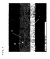
- FIG. 1 is a photograph of a section of an exemplary negative electrode of the present invention.
- the negative electrode of FIG. 1 comprises a current collector 1 and a mixed material layer carried on one side of the current collector 1.
- the mixed material layer includes graphite particles 3 with a large particle size and particles of alloying material 2 that are positioned so as to fill the gaps between the graphite particles 3. Also, there are suitable gaps around the particles of alloying material 2. Accordingly, when the particles 2 expand, such a structure can lessen the expansion and facilitate collection of current upon the expansion. Also, this structure makes it possible to make the alloying material fully contact an electrolyte, leading to an improvement in high-rate discharge characteristics and charge/discharge cycle characteristics.
- the maximum particle size of the alloying material is 10 ⁇ m or less, and more preferably 5 ⁇ m or less. If the maximum particle size of the alloying material is larger than 10 ⁇ m, the proportion of the particles of alloying material entering between the graphite particles decreases, and the proportion of the particles of alloying material that agglomerate increases. If the particles of the alloy material agglomerate, they push against one another when they expand, which may cause the negative electrode to expand excessively.
- At least a part of the alloying material is desirably adhered to the surface of the graphite via a binder.
- a binder is excellent in terms of easing excessive expansion and maintaining the current collecting property.
- the alloying material can be stably present in the gaps between the graphite particles.
- excessive expansion of the negative electrode material mixture layer is suppressed.
- the alloying material is fixed to the surfaces of the graphite particles, current collection can be constantly ensured.
- the ratio of the mean particle size of the alloying material (R alloy) and the mean particle size of the graphite (R graphite), i.e., the R alloy/R graphite ratio, is desirably in the range of 0.15 to 0.90.
- the mean particle size of the graphite (R graphite) is 18 ⁇ m
- the preferable range of the mean particle size of the alloying material (R alloy) is 2.7 ⁇ m to 16.2 ⁇ m.
- the maximum particle size of the alloying material be 10 ⁇ m or less. Accordingly, the optimum range of R alloy is not less than 2.7 ⁇ m and not more than 10 ⁇ m.
- the R alloy/R graphite ratio is less than 0.15, a large number of particles of the alloying material tend to be squeezed into the gaps between the graphite particles. Thus, when the particles of the alloying material expand, they push against one another, which may cause the negative electrode to expand relatively largely.
- the R alloy/R graphite ratio is greater than 0.9, the size of the graphite particles is almost equal to the size of the particles of alloying material. Thus, the gaps inside the negative electrode, which serve to lessen the expansion of the particles of alloying material, decrease.
- the most preferable range of the R alloy/R graphite ratio is 0.2 to 0.4. In this range, the ability to lessen the expansion of the alloying material becomes highest.
- the negative electrode can further include an auxiliary conductive agent.
- the auxiliary conductive agent is mainly added to improve the efficiency of collecting current from the alloy material. It is therefore preferred that the auxiliary conductive agent exists mainly near the particles of alloying material.
- the specific surface area of the auxiliary conductive agent is desirably 10 m 2 /g or more.
- an auxiliary conductive agent having a specific surface area of less than 10 m 2 /g can improve the current-collecting efficiency, it is desirable to use an auxiliary conductive agent having a specific surface area of 10 m 2 /g or more, in order to obtain the effect of improving the current-collecting efficiency by using a small amount thereof.
- the auxiliary conductive agent include carbon blacks, and among them, acetylene black is preferred.
- carbon fibers having an aspect ratio of 10 or more are also preferable as the auxiliary conductive agent. Particularly, the carbon fibers contribute to the maintenance of current collecting property between the alloying material particles or between the alloying material and the graphite.
- At least one end of the carbon fibers is desirably adhered to the surface of the alloying material or graphite, and is particularly desirably bonded (for example, chemically bonded) to the surface of the alloying material or graphite.
- the alloying material is expanding or contracting, electrons can be stably donated and accepted via the carbon fibers.
- the current collecting property is improved.
- one end of the carbon fiber be adhered or bonded to the alloying material while the other end be adhered or bonded to the graphite present nearby.
- the alloying material can be fixed to the graphite surface more firmly. Hence, the effect of easing the negative electrode expansion increases.
- the carbon fibers may be vapor-phase growth carbon fibers (VGCF) or carbon nanotubes.
- VGCF vapor-phase growth carbon fibers
- the carbon fibers can be included in the negative electrode as the auxiliary conductive agent.
- the carbon fibers can be grown on the surface of the alloying material and/or graphite by heating at least one of the alloying material and the graphite in the flow of a hydrocarbon gas.
- the heating atmosphere is desirably a reducing atmosphere.
- the hydrocarbon for example, methane, ethane, ethylene, acetylene, etc., can be used.
- the heating temperature is preferably 400 to 800 °C.
- carbon monoxide may be used instead of a hydrocarbon. If the heating temperature is lower than 400°C, a sufficient amount of carbon fibers may not be produced, thereby making the conductivity of the negative electrode insufficient. On the other hand, if the heating temperature is higher than 800°C, highly conductive carbon fibers are produced, but crystallization of the alloying material may proceed, resulting in degradation in electrode characteristics.
- the ratio of the auxiliary conductive agent to the total weight of the alloying material, the graphite and the auxiliary conductive agent is desirably 10% by weight or less, and more desirably 5% by weight or less.
- the negative electrode includes a binder which binds the graphite material and the alloying material together and fixes the mixed material layer to a current collector.
- the binder is selected to be a material that is electrochemically inactive with respect to Li in the potential range of the negative electrode and that has as little effect as possible on other substances.
- Suitable examples of the binder include styrene-butadiene copolymer rubber, polyacrylic acid, polyethylene, polyurethane, polymethyl methacrylate, polyvinylidene fluoride, polytetrafluoroethylene, carboxymethyl cellulose, and methyl cellulose. They may be used singly or in combination of two or more of them. With respect to the amount of the binder to be added, more is preferable, in terms of maintaining the structure of the mixed material mixture layer; however, in terms of enhancing battery capacity and discharge characteristics, less is preferable.
- the negative electrode of the present invention comprises a current collector made of a metal foil and a negative electrode mixed material layer carried on each side of the current collector, it is desirable to use copper foil or copper alloy foil as the current collector.
- copper alloy foil the copper content is preferably 90% by weight or more.
- the current collector contain an element such as P, Ag, or Cr.
- the thickness of the current collector is preferably not less than 6 ⁇ m and not greater than 40 ⁇ m. If the current collector has a thickness of less than 6 ⁇ m, it is difficult to handle and lacks sufficient strength, so that it may become broken or wrinkled when the material mixture layer expands and contracts. On the other hand, if the current collector has a thickness of more than 40 ⁇ m, the volume ratio of the current collector to the battery increases, which is disadvantageous in terms of capacity depending on the kind of the battery. Also, thick current collectors are difficult to handle, for example, difficult to bend.
- the negative electrode mixed material layer comprises a mixture of the alloying material, the graphite, the binder and the like, and it contains, if necessary, other additives, such as an auxiliary conductive agent.
- the thickness of the negative electrode mixed material layer on one side of the current collector is generally not less than 10 ⁇ m and not greater than 100 ⁇ m, and it is often not less than 50 ⁇ m and not more than 100 ⁇ m. Although the thickness of the mixed material layer may be less than 10 ⁇ m, care should be taken to see that the volume ratio of the current collector to the negative electrode does not become too large. Also, the thickness of the mixed material mixture layer may be more than 100 ⁇ m, but an electrolyte may not penetrate through to the vicinity of the current collector, thereby resulting in a degradation in high-rate discharge characteristics.
- the density of the negative electrode mixed material layer is preferably 0.8 g/cm 3 to 2 g/cm 3 in a discharged state.
- the porosity of the negative electrode mixed material layer is desirably 70% or less. The porosity is calculated as follows. the measured density of the negative electrode mixed material layer / the true density of the negative electrode mixed material layer ⁇ 100 %
- the true density of the negative electrode mixed material layer is calculated from the respective true densities of the raw materials (alloying material, graphite, binder and the like) of the negative electrode mixed material and the mixing ratio thereof.
- a non-aqueous electrolyte secondary battery includes the above-described negative electrode, a positive electrode capable of electrochemically absorbing and desorbing Li, and a non-aqueous electrolyte.
- the positive electrode may be any positive electrode that is conventionally suggested or disclosed in related arts, without any particular limitation.
- the positive electrode may be produced by conventional methods.
- the positive electrode can be obtained by mixing a positive electrode active material, a conductive agent such as carbon black and a binder such as polyvinylidene fluoride together in a liquid phase, applying the resultant paste onto a positive electrode current collector made of Al or the like, and drying and rolling it.
- the positive electrode active material may be any positive electrode active material that is conventionally suggested or disclosed in related arts, without any particular limitation.
- lithium containing transition metal compounds are preferable.
- Typical examples of the lithium containing transition metal compounds include, but are not limited to, LiCoO 2 , LiNiO 2 , LiMn 2 O 4 , and LiMnO 2 .
- Compounds obtained by replacing the transition metal element of the above-mentioned compounds with a different metal element are also used preferably. Examples include LiCo 1-x Mg x O 2 , LiNi 1-y Co y O 2 , and LiNi 1-y-z Co y Mn z O 2 (x, y, and z are positive).
- the non-aqueous electrolyte may be any electrolyte that is conventionally suggested and disclosed in related arts, without any particular limitation.
- an electrolyte comprising a non-aqueous solvent and a lithium salt that is soluble therein is preferred.
- a common non-aqueous solvent is a solvent mixture of a cyclic carbonate, such as ethylene carbonate or propylene carbonate, and a chain carbonate, such as dimethyl carbonate, diethyl carbonate, or ethyl methyl carbonate.
- ⁇ -butyrolactone, dimethoxyethane or the like may be mixed in a non-aqueous solvent.
- examples of the lithium salt include inorganic lithium fluorides and lithium imide compounds.
- the former examples include LiPF 6 and LiBF 4 . and the latter examples include LiN(CF 3 SO 2 ) 3 . Further, LiClO 4 , LiCF 3 SO 3 or the like may be mixed in the lithium salt.
- the non-aqueous electrolyte may be a gel electrolyte or a solid electrolyte.
- a separator is placed between the positive electrode and the negative electrode in order to prevent internal short-circuits therebetween.
- the separator may be made of any material that allows the non-aqueous electrolyte to pass through to a suitable extent and prevents the contact between the positive electrode and the negative electrode.
- a microporous film made of polyethylene, polypropylene or the like is generally used in non-aqueous electrolyte secondary batteries, and the thickness thereof is generally not less than 10 ⁇ m and not more than 30 ⁇ m.
- the present invention is applicable to non-aqueous electrolyte secondary batteries of various shapes, such as cylindrical, flat, coin, and rectangular shapes, and the battery shape is not particularly limited.
- the present invention is applicable to various sealing types of batteries, including batteries in which power generating elements, such as electrodes and an electrolyte, are accommodated in a metal battery case or a case made of a laminated film. There is no particular limitation with respect to how the batteries are sealed.
- negative electrodes and cylindrical batteries were produced in the following manner, and their cycle life and discharge capacity were evaluated.
- This powder mixture of 3.5 kg was placed in the container of a vibration mill (FV-20, manufactured by Chuo Kakohki Co., Ltd.). Then, 2-cm-diameter stainless steel balls were placed therein such that they occupied 70% of the internal volume of the container. After the container was evacuated, Ar (purity 99.999%, manufactured by Nippon Sanso Corporation) was introduced thereinto so as to provide a pressure of 1 atmosphere.
- Ar purity 99.999%, manufactured by Nippon Sanso Corporation
- the operating conditions of the mill were: amplitude of 8 mm and revolution frequency of 1200 rpm. Under such conditions, the mechanical alloying operation was performed for 80 hours.
- the Ti-Si alloy obtained by the above operation was removed from the container, and its particle size distribution was examined. It was found that this alloy had a wide particle size distribution of 0.5 ⁇ m to 80 ⁇ m.
- the Ti-Si alloy was classified with a sieve (10 ⁇ m mesh size), which gave an alloying material (hereinafter referred to as "alloy a" or “alloying material a”) having a maximum particle size of 10 ⁇ m and a mean particle size of 8 ⁇ m.
- the alloying material a was measured by X-ray diffraction analysis, and an XRD profile as shown in FIG. 2 was obtained. As can be seen from FIG. 2 , the alloying material a was a microcrystalline alloying material, and the size of its crystal grains (crystallites) calculated from the half width of the most intensive peak based on the Scherrer equation was 10 nm.
- the alloying material a was mixed with graphite in weight ratios as listed in Table 1.
- a negative electrode material mixture paste was prepared by adding 5 parts by weight of polyacrylic acid (molecular weight: 150,000, manufactured by Wako Pure Chemical Industries, Ltd.) as a binder per 100 parts by weight of the total of the alloy a and the graphite, and sufficiently kneading the mixture with pure water. Therein, the whole amount of the alloying material a and 2.5 parts by weight of polyacrylic acid were kneaded until they became homogeneous, and then, the graphite and the remaining polyacrylic acid were added to the mixture and kneaded.
- polyacrylic acid molecular weight: 150,000, manufactured by Wako Pure Chemical Industries, Ltd.
- the graphite used was flake graphite (KS-44) with a mean particle size of 20 ⁇ m, manufactured by Timcal Ltd.
- the negative electrode material mixture paste was applied to both sides of a current collector, made of a 10- ⁇ m-thick electrolytic copper foil (manufactured by Furukawa Circuit Foil Co., Ltd).
- the current collector applied with the paste was then dried and rolled, which gave a negative electrode comprising the current collector and a negative electrode material mixture layer carried on each side of the current collector.
- a section of the negative electrode thus obtained was observed with a scanning electron microscope (SEM), and it was found that the structure thereof was almost the same as that of FIG. 1 .
- the density of the negative electrode material mixture layer was 1.3 to 1.4 g/cm 3 , and the porosity of the negative electrode material mixture layer was 40 to 45 %.
- LiCoO 2 which is a positive electrode active material, was synthesized by mixing Li 2 CO 3 and CoCO 3 in a predetermined molar ratio, and heating the resultant mixture at 950 °C.
- the synthesized LiCoO 2 was classified into a size of 45 ⁇ m or less. 100 parts by weight of the LiCoO 2 (positive electrode active material) was fully mixed with 5 parts by weight of acetylene black serving as a conductive agent, 4 parts by weight of polyvinylidene fluoride as a binder, and a proper amount of N-methyl-2-pyrrolidone as a dispersion medium, to obtain a positive electrode material mixture paste.
- the positive electrode material mixture paste was applied on both sides of a current collector, made of a 15- ⁇ m-thick aluminum foil (manufactured by Showa Denko K.K.). The resultant current collector applied with the paste was then dried and rolled, which gave a positive electrode comprising the current collector and a positive electrode material mixture layer carried on each side of the current collector.
- a cylindrical lithium ion secondary battery as illustrated in FIG. 4 was produced.
- a positive electrode 35 and a negative electrode 36 were cut into a predetermined size.
- One end of an aluminum positive electrode lead 35a was connected to the current collector of the positive electrode.
- One end of a nickel negative electrode lead 36a was connected to the current collector of the negative electrode.
- the positive electrode 35 and the negative electrode 36 were rolled up with a separator 37 comprising a polyethylene resin microporous film, which is 20 ⁇ m in thickness and wider than the electrode plates, interposed therebetween, to produce an electrode plate group.
- the outer face of this electrode plate group was covered with the separator 37.
- An upper insulating ring 38a and a lower insulating ring 38b were fitted to the upper and lower parts of the electrode plate group, which was then placed into a battery case 31.
- the non-aqueous electrolyte used was prepared by dissolving lithium hexafluorophosphate (LiPF 6 ) at a concentration of 1 mol/L in a non-aqueous solvent mixture of ethylene carbonate and diethyl carbonate in a volume ratio of 1:1.
- LiPF 6 lithium hexafluorophosphate
- each cylindrical battery was charged at a constant charge current of 0.2 C (1 C is 1 hour-rate current) until the battery voltage reached 4.05 V, and then charged at a constant voltage of 4.05 V until the current value reached 0.01 C. Thereafter, the cylindrical battery was discharged at a current of 0.2 C until the battery voltage dropped to 2.5 V. Table 1 shows the discharge capacity.
- a negative electrode was produced by using graphite alone without using the alloying material a.
- a cylindrical lithium ion secondary battery 10 was produced in the same manner as in Example 1 except for the use of this negative electrode. Therein, 5 parts by weight of the binder (polyacrylic acid) was added per 100 parts by weight of graphite.
- a negative electrode was produced by using the alloying material alone without using graphite and using, as an auxiliary conductive agent, 10 parts by weight of acetylene black (DENKA BLACK, manufactured by Denki Kagaku Kogyo K.K.) having a specific surface area of 70 m 2 /g per 100 parts by weight of the alloying material a.
- a cylindrical lithium ion secondary battery 11 was produced in the same manner as in Example 1 except for the use of this negative electrode. Therein, 5 parts by weight of the binder (polyacrylic acid) was added per 100 parts by weight of the alloying material a.
- the batteries 1 to 6 of Example 1 using a negative electrode in which the weight percentage of the graphite relative to the total weight of the alloy a and the graphite is 50% to 95%, have improved capacities, particularly compared with Comparative Example 1, and have improved cycle lives compared with Comparative Example 2.
- the batteries of Comparative Examples 1 and 2 were disassembled after 100 cycles and evaluated for the degree of expansion. As a result, it was found that the negative electrode of Comparative Example 1 expanded 1.1-fold and the negative electrode of Comparative Example 2 expanded 3.2-fold, as compared with the thickness of the negative electrode before the charge/discharge. On the other hand, for example, the battery 3 of Example 1 was disassembled after 100 cycles and evaluated for the degree of expansion. As a result, an approximately 1.5-fold expansion was observed. That is, it was found that the batteries of Example 1 were able to suppress the expansion due to the alloying material while maintaining high capacity.
- the mixing weight ratio of graphite (KS-44, manufactured by Timcal Ltd.) and the Ti-Si alloy (alloy a) was fixed at 80:20.
- the above-mentioned acetylene black (DENKA BLACK, manufactured by Denki Kagaku Kogyo K.K., with a specific surface area of 70 m 2 /g) or graphite with a specific surface area of 14 m 2 /g (KS4, manufactured by Timcal Ltd.) was added as an auxiliary conductive agent, in parts by weight as listed in Table 3 per 100 parts by weight of the total of the alloying material a and the graphite (KS-44).
- As the binder 5 parts by weight of polyacrylic acid was added.
- cylindrical lithium ion secondary batteries 12 to 20 were produced. Therein, the whole amount of the alloying material a, 3 parts by weight of polyacrylic acid and a predetermined amount of acetylene black or KS4 were kneaded until they became homogeneous, and then, the graphite (KS-44) and the remaining polyacrylic acid were added and kneaded.
- Example 2 The batteries 12 to 20 of Example 2 were evaluated in the same manner as in Example 1.
- Table 3 shows the results.
- Battery Auxiliary conductive agent Discharge capacity (mAh) Capacity maintenance rate (%)
- Kind Amount (part by weight) 12 Acetylene black 2 1750 96 13
- Acetylene black 5 1690 95 14
- Acetylene black 10 1590 95 15
- each negative electrode of this example was observed with an SEM, and a proper amount of the auxiliary conductive agent was found to be around the particles of the alloying material a. It is considered that such arrangement of the auxiliary conductive agent ensured sufficient conductivity of the negative electrode, thereby enabling the alloying material a to exhibit its maximum capacity.
- the Ti-Si alloying material with a wide particle size distribution of 0.5 ⁇ m to 80 ⁇ m which was obtained in the same manner as in Example 1, was put through a first sieve (45 ⁇ m mesh size) to remove particles larger than 45 ⁇ m.
- the alloy was then put through a second sieve (20 ⁇ m mesh size) to remove particles smaller than 20 ⁇ m, to obtain an alloy material (hereinafter referred to as alloying material b) with a particle size distribution of 20 to 45 ⁇ m and a mean particle size of 32 ⁇ m.
- a cylindrical lithium ion secondary battery 21 was produced in the same manner as the battery 3 of Example 1 except for the use of the alloying material b.
- the Ti-Si alloying material with a wide particle size distribution of 0.5 ⁇ m to 80 ⁇ m which was obtained in the same manner as in Example 1, was put through a first sieve (20 ⁇ m mesh size) to remove particles larger than 20 ⁇ m.
- the alloying material was then put through a second sieve (10 ⁇ m mesh size) to remove particles smaller than 10 ⁇ m, to obtain an alloying material (hereinafter referred to as alloying material c) with a particle size distribution of 10 to 20 ⁇ m and a mean particle size of 13 ⁇ m.
- a cylindrical lithium ion secondary battery 22 was produced in the same manner as the battery 3 of Example 1 except for the use of the alloying material c.
- a cylindrical lithium ion secondary battery 23 was produced in the same manner as the battery 3 of Example 1 except for the use of the alloying material d.
- Example 3 The batteries 21 to 23 of Example 3 were evaluated in the same manner as in Example 1. Table 4 shows the results. Table 4 Battery Mean particle size ( ⁇ m) Maximum particle size ( ⁇ m) Discharge capacity (mAh) Capacity maintenance rate (%) 21 32 44 1690 18 22 13 18 1700 26 23 8 10 1710 60
- the batteries of this example had large initial capacities, but their charge/discharge cycle characteristics tended to be low. In the case of the batteries 21 and 22, in particular, the results were not as good as even those of Comparative Example 2. A section of the negative electrode of each of the batteries 21 to 22 was observed with an SEM, and it was found that the negative electrode had a structure different from that as shown in FIG. 1 , with graphite particles and particles of alloying material agglomerating separately.
- the batteries 21 and 22 were disassembled after 100 cycles, and their negative electrodes were observed. As a result, it was found that most of the material mixture separated from and fell off the current collector. Further, these current collectors were observed to be wrinkled and cracked at the edge thereof. This is probably because the stress exerted by the expansion of the alloy material deformed the current collectors, thereby leading to defects such as wrinkles and cracking. Also, in the battery 23, partial separation of the material mixture was observed.
- the Ti-Si alloying material (alloying material a) used in Example 1 was introduced into an electric furnace and heat-treated at 1000°C in a vacuum for 3 hours. As a result, the alloying material a turned into a highly crystalline alloying material (hereinafter referred to as alloying material e).
- the alloying material e was measured by X ray diffraction analysis, and the size of its crystal grains (crystallites) calculated from the half width of the most intensive peak based on the Scherrer equation was 1 ⁇ m.
- the particle size distribution of the alloying material e remained unchanged and the same as that of the alloying material a.
- the mean particle size of the alloying material e was 8 ⁇ m, and its maximum particle size was 10 ⁇ m.
- a cylindrical lithium ion secondary battery 24 was produced in the same manner as the battery 3 of Example 1 except for the use of the alloying material e, and then evaluated in the same manner as in Example 1. Table 5 shows the results. Table 5 Battery Crystal grain size ( ⁇ m) Discharge capacity (mAh) Capacity maintenance rate (%) 24 1 1640 11
- the battery 24 has a high capacity, but its charge/discharge cycle characteristics are low.
- the battery 24 was disassembled after 100 cycles, and its negative electrode was observed. It was found that the particles of alloying material were further pulverized into sub-micron size. The reason is considered to be that the Si crystal phase, which was produced by the heat-treatment, was expanded and destroyed by the absorption of Li.
- An alloying material was produced by the same synthesis method as that of Example 1, except for the use of Zr, Ni, Co, Mn, Fe or Cu (purity: 99.9%, particle size: 100 to 150 ⁇ m) as the transition metal M instead of metal Ti.
- the resultant alloying material was put through a sieve which was the same as that of Example 1, to obtain an alloying material with a maximum particle size of 8 ⁇ m and a mean particle size of 5 ⁇ m. Alloying materials using Zr, Ni, Co, Mn, Fe and Cu were named alloying materials f, g, h, i, j and k, respectively.
- the alloying materials f to k were measured by X ray diffraction analysis, and the resultant XRD profiles were similar to that of FIG. 2 , showing that these alloying materials were microcrystalline. Also, the size of crystal grains (crystallites) of each alloying material calculated from the half width of the most intensive peak based on the Scherrer equation was in the range of 9 to 25 nm.
- Cylindrical lithium ion secondary batteries 25 to 30 were produced in the same manner as the battery 3 of Example 1 except for the use of the alloying materials f to k, and they were evaluated in the same manner as in Example 1.
- Table 6 shows the results.
- the results of the batteries 25 to 30 indicate that the use of any of the alloying materials results in a battery having both high capacity and long cycle life. It is noted that the Ti-Si alloy (alloy a) and the Zr-Si alloy (alloy f) exhibited particularly good charge/discharge cycle characteristics. This is probably because the particles of these alloying materials have higher electronic conductivity than other alloying materials, thereby providing good charge/discharge cycle characteristics without being influenced by expansion.
- the Ti-Si alloying material with a wide particle size distribution of 0.5 ⁇ m to 80 ⁇ m which was obtained in the same manner as in Example 1, was classified with various sieves, to obtain alloying materials each having a mean particle size of 2 ⁇ m, 5 ⁇ m or 7 ⁇ m and a maximum particle size of not larger than 10 ⁇ m.
- graphite (KS-44) was crushed and classified with sieves, to obtain graphite materials each having a mean particle size of 8 ⁇ m, 13 ⁇ m, 16 ⁇ m or 20 ⁇ m (uncrushed).
- the batteries 36 and 38 had relatively short cycle lives.
- the R alloy/R graphite values of the batteries 36 and 38 were lower than 0.15.
- a section of the negative electrodes of these batteries was observed with an SEM, and it was found that a large number of particles of alloying material were squeezed and agglomerated between graphite particles. Therefore, when these batteries were disassembled after 100 cycles to observe their negative electrodes, part of the negative electrode material mixture was found to be separated from the current collector.
- the alloy a and graphite were used in the weight ratios as listed in Table 8. Also, 5 parts by weight of polyacrylic acid (molecular weight: 150,000, manufactured by Wako Pure Chemical Industries, Ltd.) serving as a binder was used per 100 parts by weight of the total of the alloy a and the graphite. However, the whole amounts of graphite and polyacrylic acid were sufficiently kneaded with pure water in advance. Thereafter, the alloy a was added to the mixture of graphite, polyacrylic acid and pure water, and the mixture was further kneaded to form a negative electrode material mixture paste. A negative electrode was produced in the same manner as in Example 1 except for the use of this paste.
- a section of the negative electrode thus obtained was observed with an SEM, and it was confirmed that the structure thereof was almost the same as that of FIG. 1 . Further, it was confirmed that the graphite surface and the alloy a were adhered at a plurality of contact points.
- the density of the negative electrode material mixture layer was 1.3 g/cm 3 , and the porosity of the negative electrode material mixture layer was 45 %.
- the batteries 39 to 44 exhibited slightly higher capacities and improved cycle characteristics in comparison with the batteries 1 to 6 of Example 1. After the evaluation, these batteries were disassembled and examined. As a result, it was found that the negative electrode expansion was 1.3- to 1.4-fold, which was low. Also, the batteries 4 and 42 were disassembled and their negative electrodes were observed with an SEM. As a result, in the negative electrode of the battery 4, a part of the mixture layer surface was bulged. On the other hand, in the battery 42, the surface was almost flat and smooth. In the batteries of Example 6, the alloying material was fixed to the graphite surface via the binder, and this is thought to be the reason why excessive expansion was suppressed.
- a negative electrode was produced in the same manner as the battery 4 of Example 1, except that 3 parts by weight of VGCF (average length: 20 ⁇ m, aspect ratio: 500, manufactured by Showa Denko K.K.) was added as the carbon fibers per 100 parts by weight of the total of the alloy a and the graphite. Using this negative electrode, a battery 45 was produced in the same manner as in Example 1.
- VGCF average length: 20 ⁇ m, aspect ratio: 500, manufactured by Showa Denko K.K.
- the alloy a was mounted on a SiO 2 boat, which was then placed in a tubular furnace. The interior of the furnace was maintained at a vacuum of 3.0 ⁇ 10 -1 Pa. Methane was circulated together with a mixed gas of helium and hydrogen inside the vacuum furnace at a flow rate of 10 sccm. In this state, the alloy a was heated at 500°C for 30 minutes. As a result, carbon fibers with an aspect ratio of approximately 20 to 100 were successfully grown on the surface of the alloy a. The amount of carbon fibers produced was 6 parts by weight per 100 parts by weight of the alloy a.
- a negative electrode was produced in the same manner as the battery 4 of Example 1 except for the use of the composite material of the alloy a and carbon fibers thus obtained instead of the alloy a. Using this negative electrode, a battery 46 was produced in the same manner as in Example 1.
- the amount of carbon fibers produced was 6 parts by weight per 100 parts by weight of the alloy a.
- a negative electrode was produced in the same manner as the battery 4 of Example 1 except for the use of the composite material of the alloy a, graphite and carbon fibers thus obtained instead of the alloy a and graphite. Using this negative electrode, a battery 47 was produced in the same manner as in Example 1.
- the batteries 45 to 47 exhibited improved charge/discharge cycle characteristics, as compared with the battery 4. That is, the addition of carbon fibers to the negative electrode was effective in improving the charge/discharge cycle characteristics. Also, when carbon fibers were bonded to the alloying material or graphite, the improvement in charge/discharge cycle characteristics was greater. This is probably because the current collecting property was improved.
- the negative electrode for a non-aqueous electrolyte secondary battery in accordance with the present invention provides an excellent non-aqueous electrolyte secondary battery having both high capacity and good charge/discharge cycle characteristics.
- the present invention is applicable to non-aqueous electrolyte secondary batteries in any form.
- the present invention is applicable not only to cylindrical batteries described in Examples, but also to batteries of coin, rectangular, or flat shape with a wound or layered electrode plate group.
- the non-aqueous electrolyte secondary battery of the present invention is useful as a main power source of mobile communications appliances or portable electronic appliances.
Claims (11)
- Électrode négative destinée à un accumulateur électrique à électrolyte non aqueux, comprenant du graphite et au moins un matériau d'alliage capable d'absorber et de désorber électrochimiquement du Li,
ledit matériau d'alliage comprenant une phase A composée principalement de Si et une phase B comprenant un composé intermétallique d'au moins un élément des métaux de transition et du Si,
au moins l'une de ladite phase A et de ladite phase B comprenant une région microcristalline ou amorphe,
le pourcentage en poids de ladite phase A par rapport au poids total de ladite phase A et de ladite phase B étant supérieur à 40 % et non supérieur à 95 %,
le pourcentage en poids dudit graphite par rapport au poids total dudit matériau d'alliage et dudit graphite n'étant pas inférieur à 50 % et non supérieur à 95 %, et
ledit matériau d'alliage possédant une taille de particule maximum de 10 µm ou moins. - Électrode négative destinée à un accumulateur électrique à électrolyte non aqueux en conformité avec la revendication 1, dans laquelle ledit matériau d'alliage se trouve dans les trous existant entre les particules dudit graphite.
- Électrode négative destinée à un accumulateur électrique à électrolyte non aqueux en conformité avec l'une quelconque des revendications 1 ou 2, comprenant en outre un liant, dans lequel au moins une partie dudit matériau d'alliage est collé à la surface dudit graphite par l'intermédiaire du liant.
- Électrode négative destinée à un accumulateur électrique à électrolyte non aqueux en conformité avec l'une quelconque des revendications 1 à 3, dans laquelle le rapport de la taille de particule moyenne dudit matériau d'alliage à la taille de particule moyenne dudit graphite se situe dans la plage de 0,15 à 0,90.
- Électrode négative destinée à un accumulateur électrique à électrolyte non aqueux en conformité avec l'une quelconque des revendications 1 à 4, comprenant en outre un agent conducteur auxiliaire, ledit agent conducteur auxiliaire possédant une aire de surface spécifique de 10 m2/g ou plus.
- Électrode négative destinée à un accumulateur électrique à électrolyte non aqueux en conformité avec la revendication 5, dans laquelle ledit agent conducteur auxiliaire comprend des fibres de carbone possédant un rapport de longueur de 10 ou plus, et au moins une extrémité desdites fibres de carbone est collée ou liée audit matériau d'alliage.
- Électrode négative destinée à un accumulateur électrique à électrolyte non aqueux en conformité avec la revendication 6, dans laquelle une extrémité d'au moins une partie desdites fibres de carbone est collée ou liée au matériau d'alliage tandis que l'autre extrémité est collée ou liée audit graphite.
- Électrode négative destinée à un accumulateur électrique à électrolyte non aqueux en conformité avec la revendication 6 ou la revendication 7, dans laquelle lesdites fibres de carbone sont obtenues en chauffant au moins l'un du matériau d'alliage et dudit graphite dans le flux d'un gaz d'hydrocarbure.
- Électrode négative destinée à un accumulateur électrique à électrolyte non aqueux en conformité avec l'une quelconque des revendications 4 à 8, dans laquelle le pourcentage en poids dudit agent conducteur auxiliaire par rapport au poids total dudit matériau d'alliage, dudit graphite et dudit agent conducteur auxiliaire est de 10 % ou moins.
- Accumulateur d'électricité à électrolyte non aqueux comprenant une électrode positive capable d'absorber et de désorber électrochimiquement du Li, une électrode négative et un électrolyte non aqueux, dans lequel ladite électrode négative est en conformité avec l'une quelconque des revendications précédentes.
- Appareil de communication mobile ou appareil électronique portable comprenant un accumulateur électrique à électrolyte non aqueux selon la revendication 10.
Applications Claiming Priority (1)
| Application Number | Priority Date | Filing Date | Title |
|---|---|---|---|
| JP2004330608 | 2004-11-15 |
Publications (2)
| Publication Number | Publication Date |
|---|---|
| EP1657768A1 EP1657768A1 (fr) | 2006-05-17 |
| EP1657768B1 true EP1657768B1 (fr) | 2008-05-28 |
Family
ID=35797193
Family Applications (1)
| Application Number | Title | Priority Date | Filing Date |
|---|---|---|---|
| EP05256937A Active EP1657768B1 (fr) | 2004-11-15 | 2005-11-10 | Electrode négative pour batterie secondaire à électrolyte non aqueux et batterie secondaire à électrolyte non aqueux comprenant celle-ci |
Country Status (5)
| Country | Link |
|---|---|
| US (2) | US7635540B2 (fr) |
| EP (1) | EP1657768B1 (fr) |
| KR (1) | KR100692778B1 (fr) |
| CN (1) | CN100433416C (fr) |
| DE (1) | DE602005007151D1 (fr) |
Cited By (16)
| Publication number | Priority date | Publication date | Assignee | Title |
|---|---|---|---|---|
| US7683359B2 (en) | 2002-11-05 | 2010-03-23 | Nexeon Ltd. | Structured silicon anode |
| US8101298B2 (en) | 2006-01-23 | 2012-01-24 | Nexeon Ltd. | Method of fabricating fibres composed of silicon or a silicon-based material and their use in lithium rechargeable batteries |
| US8585918B2 (en) | 2006-01-23 | 2013-11-19 | Nexeon Ltd. | Method of etching a silicon-based material |
| US8642211B2 (en) | 2007-07-17 | 2014-02-04 | Nexeon Limited | Electrode including silicon-comprising fibres and electrochemical cells including the same |
| US8772174B2 (en) | 2010-04-09 | 2014-07-08 | Nexeon Ltd. | Method of fabricating structured particles composed of silicon or silicon-based material and their use in lithium rechargeable batteries |
| US8870975B2 (en) | 2007-07-17 | 2014-10-28 | Nexeon Ltd. | Method of fabricating structured particles composed of silicon or a silicon-based material and their use in lithium rechargeable batteries |
| US8932759B2 (en) | 2008-10-10 | 2015-01-13 | Nexeon Ltd. | Method of fabricating structured particles composed of silicon or a silicon-based material |
| US8945774B2 (en) | 2010-06-07 | 2015-02-03 | Nexeon Ltd. | Additive for lithium ion rechageable battery cells |
| US8962183B2 (en) | 2009-05-07 | 2015-02-24 | Nexeon Limited | Method of making silicon anode material for rechargeable cells |
| US9012079B2 (en) | 2007-07-17 | 2015-04-21 | Nexeon Ltd | Electrode comprising structured silicon-based material |
| US9184438B2 (en) | 2008-10-10 | 2015-11-10 | Nexeon Ltd. | Method of fabricating structured particles composed of silicon or a silicon-based material and their use in lithium rechargeable batteries |
| US9252426B2 (en) | 2007-05-11 | 2016-02-02 | Nexeon Limited | Silicon anode for a rechargeable battery |
| US9608272B2 (en) | 2009-05-11 | 2017-03-28 | Nexeon Limited | Composition for a secondary battery cell |
| US9647263B2 (en) | 2010-09-03 | 2017-05-09 | Nexeon Limited | Electroactive material |
| US9853292B2 (en) | 2009-05-11 | 2017-12-26 | Nexeon Limited | Electrode composition for a secondary battery cell |
| US9871248B2 (en) | 2010-09-03 | 2018-01-16 | Nexeon Limited | Porous electroactive material |
Families Citing this family (31)
| Publication number | Priority date | Publication date | Assignee | Title |
|---|---|---|---|---|
| US7955735B2 (en) * | 2004-11-15 | 2011-06-07 | Panasonic Corporation | Non-aqueous electrolyte secondary battery |
| KR100794192B1 (ko) | 2006-09-08 | 2008-01-14 | 한국과학기술연구원 | 리튬 이차 전지용 탄소 피복 실리콘-흑연 복합 음극 소재의 제조 방법 및 이를 포함하는 이차 전지의 제조방법 |
| JP5211526B2 (ja) | 2007-03-29 | 2013-06-12 | Tdk株式会社 | 全固体リチウムイオン二次電池及びその製造方法 |
| JP5211527B2 (ja) * | 2007-03-29 | 2013-06-12 | Tdk株式会社 | 全固体リチウムイオン二次電池及びその製造方法 |
| JP5157216B2 (ja) * | 2007-03-29 | 2013-03-06 | Tdk株式会社 | 活物質の製造方法及び活物質 |
| RU2011144388A (ru) * | 2009-04-03 | 2013-05-10 | Басф Се | Способ получения композиционных материалов |
| US8992801B2 (en) | 2009-04-03 | 2015-03-31 | Basf Se | Electroactive material, and use thereof in anodes for lithium-ion cells |
| WO2011037142A1 (fr) | 2009-09-25 | 2011-03-31 | 日本ゼオン株式会社 | Anode à utiliser dans une batterie secondaire lithium-ion et batterie secondaire au lithium-ion |
| JP5103496B2 (ja) * | 2010-03-09 | 2012-12-19 | 日立ビークルエナジー株式会社 | リチウムイオン二次電池 |
| CN102959786B (zh) * | 2011-03-09 | 2015-04-22 | 松下电器产业株式会社 | 带端子电池 |
| CN102916167B (zh) * | 2011-08-04 | 2016-08-03 | 上海交通大学 | 用作锂离子电池负极材料的介孔硅复合物及其制备方法 |
| US9716264B2 (en) * | 2012-02-21 | 2017-07-25 | Samsung Sdi Co., Ltd. | Electrode for lithium secondary battery, method of manufacturing the electrode, and lithium secondary battery including the electrode |
| CN104813509B (zh) * | 2012-11-22 | 2017-06-23 | 日产自动车株式会社 | 电气设备用负极和使用了其的电气设备 |
| US20150303455A1 (en) * | 2012-11-22 | 2015-10-22 | Nissan Motor Co., Ltd. | Negative electrode for electric device and electric device using the same |
| US10741842B2 (en) * | 2012-12-07 | 2020-08-11 | Samsung Electronics Co., Ltd. | Solid-state battery |
| US20150357632A1 (en) * | 2013-02-07 | 2015-12-10 | Hitachi, Ltd. | Negative electrode active material for lithium secondary batteries, and lithium secondary battery |
| JP6371504B2 (ja) * | 2013-02-19 | 2018-08-08 | 山陽特殊製鋼株式会社 | 蓄電デバイス用Si系合金負極材料およびそれを用いた電極 |
| KR20140139845A (ko) * | 2013-05-28 | 2014-12-08 | 삼성에스디아이 주식회사 | 리튬 이차 전지용 전극, 및 상기 전극을 포함하는 리튬 이차 전지 |
| JP6202106B2 (ja) * | 2014-01-24 | 2017-09-27 | 日産自動車株式会社 | 電気デバイス |
| WO2015111187A1 (fr) | 2014-01-24 | 2015-07-30 | 日産自動車株式会社 | Dispositif électrique |
| KR102323025B1 (ko) * | 2015-02-26 | 2021-11-10 | 일진전기 주식회사 | 리튬 이차전지용 음극판 및 이를 포함한 리튬 이차전지 |
| US10637061B2 (en) * | 2015-05-29 | 2020-04-28 | Nec Corporation | Lithium ion secondary battery |
| EP3352188B1 (fr) | 2016-01-22 | 2020-07-29 | Asahi Kasei Kabushiki Kaisha | Élément de stockage de type au lithium non aqueux |
| EP3392891B1 (fr) * | 2016-01-22 | 2020-01-08 | Asahi Kasei Kabushiki Kaisha | Élément de stockage au lithium non aqueux |
| WO2017126689A1 (fr) | 2016-01-22 | 2017-07-27 | 旭化成株式会社 | Élément de stockage au lithium non aqueux |
| KR102007130B1 (ko) * | 2016-01-22 | 2019-10-01 | 아사히 가세이 가부시키가이샤 | 비수계 리튬형 축전 소자 |
| TWI627648B (zh) | 2016-01-22 | 2018-06-21 | Asahi Chemical Ind | 正極前驅體 |
| CN108475584B (zh) | 2016-01-22 | 2019-07-02 | 旭化成株式会社 | 非水系锂型蓄电元件 |
| US10396361B2 (en) | 2016-01-22 | 2019-08-27 | Asahi Kasei Kabushiki Kaisha | Nonaqueous lithium-type power storage element |
| JP6262402B2 (ja) | 2016-01-22 | 2018-01-17 | 旭化成株式会社 | 非水系リチウム蓄電素子 |
| US20220059812A1 (en) * | 2018-12-19 | 2022-02-24 | Novonix Battery Testing Services Inc. | Electrochemically active dispersions and composites for rechargeable battery anodes |
Family Cites Families (26)
| Publication number | Priority date | Publication date | Assignee | Title |
|---|---|---|---|---|
| US556721A (en) * | 1896-03-17 | brtggs | ||
| CA1173900A (fr) | 1982-06-30 | 1984-09-04 | Hydro-Quebec | Anodes composites et souples de pile au lithium en milieu non-aqueux |
| JPH0724219B2 (ja) | 1986-07-04 | 1995-03-15 | 日立マクセル株式会社 | リチウム二次電池 |
| US4957833A (en) | 1988-12-23 | 1990-09-18 | Bridgestone Corporation | Non-aqueous liquid electrolyte cell |
| JP3177257B2 (ja) * | 1991-01-08 | 2001-06-18 | 三洋電機株式会社 | 非水電解液二次電池 |
| JP3168600B2 (ja) | 1991-05-07 | 2001-05-21 | 松下電器産業株式会社 | 非水電解質二次電池用負極 |
| JP3079343B2 (ja) | 1993-07-13 | 2000-08-21 | セイコーインスツルメンツ株式会社 | 非水電解質二次電池及びその製造方法 |
| DE69531849T2 (de) | 1994-05-30 | 2004-08-05 | Canon K.K. | Wiederaufladbare Lithiumbatterie |
| EP0855752B1 (fr) | 1997-01-28 | 2006-11-29 | Canon Kabushiki Kaisha | Electrode de corps structural, accumulateur pourvu de cet électrode de corps structural et procédé de fabrication d'une telle éléctrode et un tel accumulateur |
| JP3805053B2 (ja) | 1997-02-10 | 2006-08-02 | 旭化成エレクトロニクス株式会社 | リチウム二次電池 |
| JP3846661B2 (ja) | 1997-02-24 | 2006-11-15 | 日立マクセル株式会社 | リチウム二次電池 |
| US6090505A (en) * | 1997-06-03 | 2000-07-18 | Matsushita Electric Industrial Co., Ltd. | Negative electrode materials for non-aqueous electrolyte secondary batteries and said batteries employing the same materials |
| US6517974B1 (en) | 1998-01-30 | 2003-02-11 | Canon Kabushiki Kaisha | Lithium secondary battery and method of manufacturing the lithium secondary battery |
| KR100366978B1 (ko) * | 1998-09-08 | 2003-01-09 | 마츠시타 덴끼 산교 가부시키가이샤 | 비수전해질 이차전지용 음극재료와 그 제조방법 |
| EP2219253B1 (fr) | 1998-09-18 | 2015-06-10 | Canon Kabushiki Kaisha | Matériau d'électrode |
| KR20070091696A (ko) | 1998-09-18 | 2007-09-11 | 윌리엄 마쉬 라이스 유니버시티 | 탄소 나노튜브들의 로프 |
| JP2000243396A (ja) | 1999-02-23 | 2000-09-08 | Hitachi Ltd | リチウム二次電池とその製造方法及びその負極材並びに電気機器 |
| JP4244478B2 (ja) | 1999-04-14 | 2009-03-25 | ソニー株式会社 | 負極材料及びそれを用いた非水電解質電池 |
| US6541156B1 (en) | 1999-11-16 | 2003-04-01 | Mitsubishi Chemical Corporation | Negative electrode material for non-aqueous lithium secondary battery, method for manufacturing the same, and non-aqueous lithium secondary battery using the same |
| JP3882447B2 (ja) | 2000-02-29 | 2007-02-14 | 松下電器産業株式会社 | 非水電解質二次電池 |
| JP4767428B2 (ja) | 2000-03-07 | 2011-09-07 | パナソニック株式会社 | 非水電解質二次電池 |
| JP2001291512A (ja) | 2000-04-05 | 2001-10-19 | Matsushita Electric Ind Co Ltd | 非水電解質二次電池 |
| JP2003223892A (ja) * | 2002-01-31 | 2003-08-08 | Osaka Gas Co Ltd | リチウム二次電池用負極材の製造方法とリチウム二次電池 |
| WO2004049473A2 (fr) | 2002-11-26 | 2004-06-10 | Showa Denko K.K. | Materiau d'electrode et procedes de production et d'utilisation de celui-ci |
| CN1322611C (zh) | 2003-03-26 | 2007-06-20 | 佳能株式会社 | 电极材料、具有该材料的构造体和具有该构造体的二次电池 |
| JP3954001B2 (ja) * | 2003-10-01 | 2007-08-08 | 三星エスディアイ株式会社 | リチウム二次電池用負極活物質及びリチウム二次電池及びリチウム二次電池用負極活物質の製造方法 |
-
2005
- 2005-05-02 US US11/119,208 patent/US7635540B2/en active Active
- 2005-10-26 US US11/258,218 patent/US7537862B2/en active Active
- 2005-11-03 KR KR1020050104822A patent/KR100692778B1/ko active IP Right Grant
- 2005-11-10 DE DE602005007151T patent/DE602005007151D1/de active Active
- 2005-11-10 EP EP05256937A patent/EP1657768B1/fr active Active
- 2005-11-15 CN CNB2005101201884A patent/CN100433416C/zh active Active
Cited By (28)
| Publication number | Priority date | Publication date | Assignee | Title |
|---|---|---|---|---|
| US7683359B2 (en) | 2002-11-05 | 2010-03-23 | Nexeon Ltd. | Structured silicon anode |
| US7842535B2 (en) | 2002-11-05 | 2010-11-30 | Nexeon Ltd. | Structured silicon anode |
| US8017430B2 (en) | 2002-11-05 | 2011-09-13 | Nexeon Ltd. | Structured silicon anode |
| US8384058B2 (en) | 2002-11-05 | 2013-02-26 | Nexeon Ltd. | Structured silicon anode |
| US8101298B2 (en) | 2006-01-23 | 2012-01-24 | Nexeon Ltd. | Method of fabricating fibres composed of silicon or a silicon-based material and their use in lithium rechargeable batteries |
| US8585918B2 (en) | 2006-01-23 | 2013-11-19 | Nexeon Ltd. | Method of etching a silicon-based material |
| US8597831B2 (en) | 2006-01-23 | 2013-12-03 | Nexeon Ltd. | Method of fabricating fibres composed of silicon or a silicon-based material and their use in lithium rechargeable batteries |
| US9583762B2 (en) | 2006-01-23 | 2017-02-28 | Nexeon Limited | Method of fabricating fibres composed of silicon or a silicon-based material and their use in lithium rechargeable batteries |
| US9871249B2 (en) | 2007-05-11 | 2018-01-16 | Nexeon Limited | Silicon anode for a rechargeable battery |
| US9252426B2 (en) | 2007-05-11 | 2016-02-02 | Nexeon Limited | Silicon anode for a rechargeable battery |
| US9012079B2 (en) | 2007-07-17 | 2015-04-21 | Nexeon Ltd | Electrode comprising structured silicon-based material |
| US8870975B2 (en) | 2007-07-17 | 2014-10-28 | Nexeon Ltd. | Method of fabricating structured particles composed of silicon or a silicon-based material and their use in lithium rechargeable batteries |
| US8642211B2 (en) | 2007-07-17 | 2014-02-04 | Nexeon Limited | Electrode including silicon-comprising fibres and electrochemical cells including the same |
| US8940437B2 (en) | 2007-07-17 | 2015-01-27 | Nexeon Limited | Method of fabricating structured particles composed of silicon or a silicon-based material and their use in lithium rechargeable batteries |
| US9871244B2 (en) | 2007-07-17 | 2018-01-16 | Nexeon Limited | Method of fabricating structured particles composed of silicon or a silicon-based material and their use in lithium rechargeable batteries |
| US8932759B2 (en) | 2008-10-10 | 2015-01-13 | Nexeon Ltd. | Method of fabricating structured particles composed of silicon or a silicon-based material |
| US9184438B2 (en) | 2008-10-10 | 2015-11-10 | Nexeon Ltd. | Method of fabricating structured particles composed of silicon or a silicon-based material and their use in lithium rechargeable batteries |
| US8962183B2 (en) | 2009-05-07 | 2015-02-24 | Nexeon Limited | Method of making silicon anode material for rechargeable cells |
| US9553304B2 (en) | 2009-05-07 | 2017-01-24 | Nexeon Limited | Method of making silicon anode material for rechargeable cells |
| US9853292B2 (en) | 2009-05-11 | 2017-12-26 | Nexeon Limited | Electrode composition for a secondary battery cell |
| US10050275B2 (en) | 2009-05-11 | 2018-08-14 | Nexeon Limited | Binder for lithium ion rechargeable battery cells |
| US9608272B2 (en) | 2009-05-11 | 2017-03-28 | Nexeon Limited | Composition for a secondary battery cell |
| US8772174B2 (en) | 2010-04-09 | 2014-07-08 | Nexeon Ltd. | Method of fabricating structured particles composed of silicon or silicon-based material and their use in lithium rechargeable batteries |
| US9368836B2 (en) | 2010-06-07 | 2016-06-14 | Nexeon Ltd. | Additive for lithium ion rechargeable battery cells |
| US8945774B2 (en) | 2010-06-07 | 2015-02-03 | Nexeon Ltd. | Additive for lithium ion rechageable battery cells |
| US9871248B2 (en) | 2010-09-03 | 2018-01-16 | Nexeon Limited | Porous electroactive material |
| US9647263B2 (en) | 2010-09-03 | 2017-05-09 | Nexeon Limited | Electroactive material |
| US9947920B2 (en) | 2010-09-03 | 2018-04-17 | Nexeon Limited | Electroactive material |
Also Published As
| Publication number | Publication date |
|---|---|
| DE602005007151D1 (de) | 2008-07-10 |
| KR20060054138A (ko) | 2006-05-22 |
| CN1761085A (zh) | 2006-04-19 |
| KR100692778B1 (ko) | 2007-03-12 |
| US20060105242A1 (en) | 2006-05-18 |
| US7635540B2 (en) | 2009-12-22 |
| US7537862B2 (en) | 2009-05-26 |
| US20060102474A1 (en) | 2006-05-18 |
| EP1657768A1 (fr) | 2006-05-17 |
| CN100433416C (zh) | 2008-11-12 |
Similar Documents
| Publication | Publication Date | Title |
|---|---|---|
| EP1657768B1 (fr) | Electrode négative pour batterie secondaire à électrolyte non aqueux et batterie secondaire à électrolyte non aqueux comprenant celle-ci | |
| JP4061586B2 (ja) | 非水電解質二次電池用正極活物質及びそれを用いた非水電解質二次電池 | |
| JP3995050B2 (ja) | リチウムイオン二次電池負極材料用複合粒子およびその製造方法、リチウムイオン二次電池用負極材料および負極、ならびにリチウムイオン二次電池 | |
| US7682744B2 (en) | Lithium secondary battery | |
| KR100855166B1 (ko) | 비수전해액 이차전지용 혹은 비수전해액 전기화학캐패시터용의 복합 전극 활물질 및 그 제조법 | |
| US8906557B2 (en) | Anode active material and method of preparing the same | |
| US7858232B2 (en) | Non-aqueous electrolyte secondary battery | |
| US7771876B2 (en) | Anode active material method of manufacturing the same and nonaqueous electrolyte secondary battery using the same | |
| US8586246B2 (en) | Positive electrode active material, positive electrode using the same and non-aqueous electrolyte secondary battery | |
| JP4794972B2 (ja) | 非水電解質二次電池用負極およびそれを含む非水電解質二次電池 | |
| JP3957692B2 (ja) | リチウムイオン二次電池負極材料用複合黒鉛粒子、負極およびリチウムイオン二次電池 | |
| JP5043344B2 (ja) | 非水電解質二次電池用負極 | |
| US20130004847A1 (en) | High energy lithium ion batteries with particular negative electrode compositions | |
| JP4996830B2 (ja) | リチウムイオン二次電池負極用金属−黒鉛質系粒子およびその製造方法、ならびにリチウムイオン二次電池用負極材料、リチウムイオン二次電池用負極およびリチウムイオン二次電池 | |
| JP2003303585A (ja) | 電 池 | |
| JP2002117833A (ja) | 非水電解質二次電池 | |
| JP2004362789A (ja) | 負極材料及びそれを用いた二次電池 | |
| EP1959513B1 (fr) | Matériau actif composite d'anode, son procédé de préparation, et anode et batterie au lithium le contenant | |
| JP4984402B2 (ja) | 非水電解質二次電池 | |
| JP2004031217A (ja) | 電池 | |
| JP3848187B2 (ja) | 非水電解質二次電池用負極材料及び非水電解質二次電池 | |
| JP4501638B2 (ja) | リチウムイオン二次電池 | |
| JP2006107847A (ja) | 非水電解質二次電池 |
Legal Events
| Date | Code | Title | Description |
|---|---|---|---|
| PUAI | Public reference made under article 153(3) epc to a published international application that has entered the european phase |
Free format text: ORIGINAL CODE: 0009012 |
|
| AK | Designated contracting states |
Kind code of ref document: A1 Designated state(s): AT BE BG CH CY CZ DE DK EE ES FI FR GB GR HU IE IS IT LI LT LU LV MC NL PL PT RO SE SI SK TR |
|
| AX | Request for extension of the european patent |
Extension state: AL BA HR MK YU |
|
| 17P | Request for examination filed |
Effective date: 20060608 |
|
| R17C | First examination report despatched (corrected) |
Effective date: 20061026 |
|
| AKX | Designation fees paid |
Designated state(s): DE FR GB |
|
| GRAP | Despatch of communication of intention to grant a patent |
Free format text: ORIGINAL CODE: EPIDOSNIGR1 |
|
| GRAS | Grant fee paid |
Free format text: ORIGINAL CODE: EPIDOSNIGR3 |
|
| GRAA | (expected) grant |
Free format text: ORIGINAL CODE: 0009210 |
|
| AK | Designated contracting states |
Kind code of ref document: B1 Designated state(s): DE FR GB |
|
| REG | Reference to a national code |
Ref country code: GB Ref legal event code: FG4D |
|
| REF | Corresponds to: |
Ref document number: 602005007151 Country of ref document: DE Date of ref document: 20080710 Kind code of ref document: P |
|
| RAP2 | Party data changed (patent owner data changed or rights of a patent transferred) |
Owner name: PANASONIC CORPORATION |
|
| PLBE | No opposition filed within time limit |
Free format text: ORIGINAL CODE: 0009261 |
|
| STAA | Information on the status of an ep patent application or granted ep patent |
Free format text: STATUS: NO OPPOSITION FILED WITHIN TIME LIMIT |
|
| 26N | No opposition filed |
Effective date: 20090303 |
|
| REG | Reference to a national code |
Ref country code: FR Ref legal event code: PLFP Year of fee payment: 11 |
|
| REG | Reference to a national code |
Ref country code: FR Ref legal event code: PLFP Year of fee payment: 12 |
|
| REG | Reference to a national code |
Ref country code: FR Ref legal event code: PLFP Year of fee payment: 13 |
|
| REG | Reference to a national code |
Ref country code: FR Ref legal event code: PLFP Year of fee payment: 14 |
|
| P01 | Opt-out of the competence of the unified patent court (upc) registered |
Effective date: 20230808 |
|
| PGFP | Annual fee paid to national office [announced via postgrant information from national office to epo] |
Ref country code: GB Payment date: 20230921 Year of fee payment: 19 |
|
| PGFP | Annual fee paid to national office [announced via postgrant information from national office to epo] |
Ref country code: FR Payment date: 20230911 Year of fee payment: 19 |
|
| PGFP | Annual fee paid to national office [announced via postgrant information from national office to epo] |
Ref country code: DE Payment date: 20230912 Year of fee payment: 19 |