EP1650527B1 - Apparatus for measuring the surface roughness or the contour of an object - Google Patents
Apparatus for measuring the surface roughness or the contour of an object Download PDFInfo
- Publication number
- EP1650527B1 EP1650527B1 EP05256082A EP05256082A EP1650527B1 EP 1650527 B1 EP1650527 B1 EP 1650527B1 EP 05256082 A EP05256082 A EP 05256082A EP 05256082 A EP05256082 A EP 05256082A EP 1650527 B1 EP1650527 B1 EP 1650527B1
- Authority
- EP
- European Patent Office
- Prior art keywords
- driving unit
- probe
- connecting member
- workpiece
- surface roughness
- Prior art date
- Legal status (The legal status is an assumption and is not a legal conclusion. Google has not performed a legal analysis and makes no representation as to the accuracy of the status listed.)
- Ceased
Links
- 230000003746 surface roughness Effects 0.000 title claims description 34
- 239000000523 sample Substances 0.000 claims description 43
- 238000005259 measurement Methods 0.000 description 17
- 238000010586 diagram Methods 0.000 description 6
- 238000003754 machining Methods 0.000 description 4
- 238000010276 construction Methods 0.000 description 3
- 230000000694 effects Effects 0.000 description 3
- 241001422033 Thestylus Species 0.000 description 2
- 238000006073 displacement reaction Methods 0.000 description 2
- 230000003247 decreasing effect Effects 0.000 description 1
- 239000004973 liquid crystal related substance Substances 0.000 description 1
- 239000002932 luster Substances 0.000 description 1
Images
Classifications
-
- G—PHYSICS
- G01—MEASURING; TESTING
- G01B—MEASURING LENGTH, THICKNESS OR SIMILAR LINEAR DIMENSIONS; MEASURING ANGLES; MEASURING AREAS; MEASURING IRREGULARITIES OF SURFACES OR CONTOURS
- G01B5/00—Measuring arrangements characterised by the use of mechanical techniques
- G01B5/28—Measuring arrangements characterised by the use of mechanical techniques for measuring roughness or irregularity of surfaces
Definitions
- the present invention relates to a surface roughness/contour shape measuring apparatus and, more particular to a surface roughness/contour shape measuring apparatus for measuring the surface roughness and contour shape of a three-dimensional workpiece along two axis directions without moving the workpiece.
- a surface roughness/contour shape measuring apparatus measures the surface roughness or contour shape of a workpiece by moving a pickup equipped with a stylus along the surface of the workpiece and by converting the amount of displacement of the stylus into an electrical signal which is read into a computer or the like for processing.
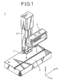
- FIG. 1 shows the basic configuration of a prior art surface roughness/contour shape measuring apparatus and also described in EP-A-1463185 .
- the surface roughness/contour shape measuring apparatus 1 is equipped with a probe (pickup) 6 for measuring the surface roughness of the workpiece placed on a table 2, and the pickup 6 is supported on a holder 5 fixed to a driving unit 4.
- the pickup 6 has a stylus 7 at its tip, and the amount of displacement of the stylus 7 is converted into a voltage by a differential transducer (not shown) built into the pickup 6. This voltage value is converted by an A/D converter into a digital signal which is input to a data processing apparatus such as a computer (not shown). Thus, measurement data showing the surface roughness of the workpiece is acquired by the data processing apparatus.
- the driving unit 4 is fitted to a column 3 mounted vertically on the table 2 and, using a motor which is driven under instruction from the data processing apparatus, the driving unit 4 can move the holder 5 in the left/right direction (X direction) which is one predesignated direction parallel to the table surface on which the workpiece is placed; further, the driving unit 4 itself can be moved along the column 3 in the up/down direction (Z direction) perpendicular to the table surface according to the height of the workpiece.
- X direction left/right direction
- Z direction up/down direction
- the direction in which the driving unit 4 can move the pickup 6 along the measurement surface of the workpiece has been limited to the X direction shown in the figure. This is because various standards (for example, JIS standard and ISO standard) defining the measurement of roughness only specify the roughness measured on a straight line.
- the measurement has been made by mounting on the table a Y-axis driving unit for moving the workpiece in the other one direction (Y direction) than the X direction on the table surface, in order to move the pickup 6 relative to the workpiece along the two in-plane directions (X and Y directions) parallel to the table surface.
- the prior art surface roughness/contour shape measuring apparatus in which the movement of the pickup 6 relative to the workpiece along one direction (Y direction) on the measurement surface is accomplished by employing a driving unit for driving the workpiece, has had the following problems.
- EP-A-0317967 describes a surface contour measuring apparatus having a probe which can be rotated about an orthogonal axis.
- US-A-4765181 describes another surface texture measuring instrument having a pick-up including a skid with a stylus.
- DE 3823993 discloses a co-ordinate measuring apparatus having a probe with a stylus being movable in 3 dimensions relative to the probe.
- a surface roughness/contour measuring apparatus comprises a probe, which is brought into contact with a surface of a workpiece, and a driving unit, which supports said probe in such a manner as to be movable linearly in one predesignated direction, and that measure a surface shape of said workpiece along the moving direction of said driving unit, wherein a connecting member capable of moving said probe linearly in one predesignated direction relative to said driving unit is provided between said probe and said driving unit, and characterised in that the connecting member comprises a first attachment engagable with a driving unit side attachment provided on said driving unit and a second attachment engagable with a holder, which holds said probe and in that the connecting member can be easily retrofitted between said probe and said driving unit by said first and second attachments.
- the present invention provides a surface roughness/ contour shape measuring apparatus that can move the probe relative to the workpiece within the orthogonal X-Y plane by employing a relatively inexpensive construction.
- the apparatus can also measure the surface shape of the workpiece within the orthogonal X-Z plane or along a sloping surface by employing a relative inexpensive construction.
- the connecting member may be fitted between the driving unit and the probe in such a manner as to drive the probe in a direction different from the direction in which the driving unit moves the probe or, alternatively, it may be fitted between the driving unit and the probe in such a manner as to move the probe in the direction that the driving unit drives the probe.
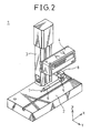
- FIG. 2 is a diagram showing the basic configuration of a surface roughness/contour shape measuring apparatus according to an embodiment of the present invention.
- the basic configuration of the surface roughness/contour shape measuring apparatus 1 is similar to the configuration shown in FIG. 1; therefore, the functional parts similar to those in FIG. 1 are designated by the same reference numerals, and the description of such parts will not be repeated here.
- the holder 5 for supporting the pickup 6 is connected to the driving unit 4 via a connecting member 8.
- the connecting member 8 is capable of moving the pickup 6 along the Y direction at right angles to the X direction which is one predesignated direction in the X-Y plane parallel to the table surface and in which the pickup 6 is moved by the driving unit 4.
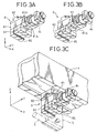
- An enlarged view of this connecting member 8 is shown in FIG. 3A.
- the connecting member 8 comprises: a main body 81; a first attachment 82 which is fixed on one side to the main body 81 and is held in engagement on the other side with a driving unit side attachment 41 (see FIG. 3C), thereby holding the main body 81 fixed relative to the driving unit 4; a movable piece 83 which is movable in the Y direction relative to the main body 81; a motor 84 for driving the movable piece 83; and a second attachment 85 which is fixed on one side to the movable piece 83 and engages on the other side with the holder 5 to hold it fixed.
- the motor 84 is driven under instruction from the data processing apparatus (not shown).
- the movable piece 83 is mounted to the main body 81 so as to be slidable in the Y direction along a prescribed surface 81A of the main body 81.
- FIG. 3B shows the condition in which the movable piece 83 is caused to slide in the Y direction along the prescribed surface 81A of the main body 81.
- FIG. 3C is a diagram showing an operating condition in which the connecting member 8 is fitted between the driving unit 4 and the holder 5 for holding the pickup 6.
- the first attachment 82 of the connecting member 8 is held in engagement with the driving unit side attachment 41 which is driven in the X direction by the driving unit 4.
- the holder 5 for holding the pickup 6 is held in engagement with the second attachment 85 fixed to the movable piece 83 which is movable in the Y direction relative to the main body 81.
- the pickup 6 can be driven in the X and Y directions by the driving unit 4 and the connecting member 8.
- This connecting member 8 can be easily retrofitted to any existing surface roughness/contour shape measuring apparatus 1 not equipped with a Y-direction driving mechanism, by using the first attachment 82 and the second attachment 85 respectively adapted to be engageable with the driving unit side attachment 41 and the holder 5 originally provided on the existing surface roughness/contour shape measuring apparatus 1.
- the connecting member 8 can be made to engage with the driving unit side attachment 41 so that the pickup 6 is driven by the connecting member 8 in the X direction.
- the direction in which the pickup 6 is driven by the connecting member 8 becomes the same as the direction in which the driving unit side attachment 41 is driven by the driving unit 4, and thus the driving range of the pickup 6 can be extended in the X direction.
- the connecting member 8 can be made to engage with the driving unit side attachment 41 so that the pickup 6 is driven by the connecting member 8 in the Z direction. This makes it possible to measure the surface shape of the workpiece in the orthogonal X-Z plane.
- the connecting member 8 can be fitted to the driving unit side attachment 41 or the holder 5 so that the pickup 6 is driven by the connecting member 8 in the direction that the connecting member 8 is driven by the driving unit 4 or in either one of the two directions orthogonal to it; furthermore, when the angle at which the first attachment 82 is fitted to the mounting surface of the main body 81 is made different from (nonparallel to) the angle at which it is fitted to the mounting surface of the driving unit side attachment 41, then it becomes possible to mount the connecting member 8 so that the pickup 6 can be driven by the connecting member 8 in a direction tilted (at an angle) with respect to the X direction.
- an angle adjusting mechanism such as a universal head may be provided to the driving unit side attachment 41 or the first attachment 82 in order to adjust the relative angle between the direction in which the pickup 6 is driven by the connecting member 8 and the direction in which the connecting member 8 is driven by the driving unit 4.
- the probe when measuring the surface roughness of a workpiece such as a machining mark on a cutting tool, for example, it is a general rule to make the measurement by moving the probe at right angles to the machining direction of the workpiece. If the probe is to be moved in such a measuring direction by using, for example, a conventional XY axis moving mechanism, the probe moves in jagged fashion depending on the XY resolution of the XY axis moving mechanism, and this causes measurement errors.
- the moving direction of the connecting member 8 can be set as desired in accordance with the machining direction, it becomes possible to prevent such measurement errors by making the measurement, for example, by setting the moving direction of the connecting member 8, so as to match the machining mark on the cutting tool. Further, it also becomes possible to efficiently measure the measurement surface if it is tilted in an arbitrary direction.
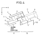
- the connecting member 8 When measuring a sawtooth face such as shown in FIG. 4, the connecting member 8 is fitted so that the pickup 6 is driven by the connecting member 8 in a second axis direction along the sawtooth face within the XZ plane.
- the connecting member 8 moves the pickup 6 from position E to position F while the connecting member 8 is held fixed at position C by the driving unit 4.
- the driving unit 4 moves the connecting member 8 to position D, while on the other hand, the connecting member 8 moves the pickup 6 back to position E', and then moves the pickup 6 from position E' to position F' to measure a tooth face portion B, in the same manner as the measurement of the tool face portion A.
- the sawtooth face can be measured with high resolution and in a continuous fashion.
- the surface roughness/contour shape measuring apparatus 1 can easily measure the surface roughness/contour shape of workpiece along the XY plane parallel to the table surface.
- the cylindrically shaped workpiece to be placed on its side on the table 2 may be placed on a rotating table for rotating the workpiece about the Z axis, and the measurement may be made in this condition.
- the pickup can be moved relative to the workpiece within the measurement plane without moving the workpiece.
- the measurement can be made not only in the orthogonal XY plane and the orthogonal XZ plane but also along various sloping surfaces outside these orthogonal planes.
- the X direction refers to one predesignated direction parallel to the mounting surface on which the workpiece is mounted, that is, the direction in which the probe is driven by the driving unit
- the Y direction refers to the another direction parallel to the mounting surface but different from the X direction
- the Z direction refers to the direction perpendicular to the mounting surface.
- the measurable range can be extended in the direction (X direction) along which the driving unit moves the probe.
- the invention also makes it possible to measure a sawtooth face in a continuous fashion and with high resolution.
- the present invention can be extensively applied to measuring apparatuses that measure the surface shape of a workpiece by moving a probe such as a stylus along the surface of the workpiece.
Landscapes
- Physics & Mathematics (AREA)
- General Physics & Mathematics (AREA)
- Length Measuring Devices With Unspecified Measuring Means (AREA)
- A Measuring Device Byusing Mechanical Method (AREA)
Applications Claiming Priority (1)
| Application Number | Priority Date | Filing Date | Title |
|---|---|---|---|
| JP2004305253A JP4570437B2 (ja) | 2004-10-20 | 2004-10-20 | 表面粗さ/輪郭形状測定装置 |
Publications (2)
| Publication Number | Publication Date |
|---|---|
| EP1650527A1 EP1650527A1 (en) | 2006-04-26 |
| EP1650527B1 true EP1650527B1 (en) | 2008-01-02 |
Family
ID=35427274
Family Applications (1)
| Application Number | Title | Priority Date | Filing Date |
|---|---|---|---|
| EP05256082A Ceased EP1650527B1 (en) | 2004-10-20 | 2005-09-29 | Apparatus for measuring the surface roughness or the contour of an object |
Country Status (4)
| Country | Link |
|---|---|
| US (1) | US7328518B2 (enExample) |
| EP (1) | EP1650527B1 (enExample) |
| JP (1) | JP4570437B2 (enExample) |
| DE (1) | DE602005004092T2 (enExample) |
Families Citing this family (14)
| Publication number | Priority date | Publication date | Assignee | Title |
|---|---|---|---|---|
| JP2006300823A (ja) * | 2005-04-22 | 2006-11-02 | Tokyo Seimitsu Co Ltd | 表面粗さ/輪郭形状測定装置 |
| JP4884091B2 (ja) * | 2005-11-08 | 2012-02-22 | 株式会社ミツトヨ | 形状測定機 |
| CN101424507B (zh) * | 2007-10-30 | 2010-12-08 | 鸿富锦精密工业(深圳)有限公司 | 平面度测量装置 |
| JP4611403B2 (ja) * | 2008-06-03 | 2011-01-12 | パナソニック株式会社 | 形状測定装置及び形状測定方法 |
| CN101846508B (zh) * | 2009-03-24 | 2012-09-19 | 鸿富锦精密工业(深圳)有限公司 | 定位装置 |
| US8196306B2 (en) * | 2009-07-09 | 2012-06-12 | General Electric Company | Post-weld offset gage |
| US8701301B2 (en) * | 2011-04-19 | 2014-04-22 | Mitutoyo Corporation | Surface texture measuring instrument |
| US9333604B1 (en) * | 2012-07-19 | 2016-05-10 | Western Digital Technologies, Inc. | Manually adjustable bracket for use with a fastener mechanism |
| CN104316019A (zh) * | 2014-11-21 | 2015-01-28 | 奇瑞汽车股份有限公司 | 一种粗糙度比较样块校准固定微调装置 |
| CN107525489A (zh) * | 2016-11-22 | 2017-12-29 | 浙江大学台州研究院 | 轴的清洗和检测装置 |
| DE102017113709B4 (de) * | 2017-06-21 | 2019-01-24 | Carl Mahr Holding Gmbh | Messarmaufnahmeeinrichtung eines Messsystems |
| CN113295127B (zh) * | 2020-02-21 | 2024-06-14 | 核工业理化工程研究院 | 圆柱面与其他曲面或平面相交处圆角半径的测量方法和测量装置 |
| WO2023276637A1 (ja) | 2021-06-28 | 2023-01-05 | コニカミノルタ株式会社 | 測定器、表面評価指標の演算方法及びプログラム |
| CN115613428A (zh) * | 2022-10-13 | 2023-01-17 | 朱思静 | 一种道路检测装置及检测工艺 |
Citations (1)
| Publication number | Priority date | Publication date | Assignee | Title |
|---|---|---|---|---|
| DE3823993A1 (de) * | 1988-07-15 | 1990-01-18 | Zeiss Carl Fa | Verfahren zur koordinatenmessung an werkstuecken |
Family Cites Families (20)
| Publication number | Priority date | Publication date | Assignee | Title |
|---|---|---|---|---|
| US3129918A (en) * | 1963-03-28 | 1964-04-21 | Bradley Owen | Adjustable indicator holder |
| US3283586A (en) * | 1964-06-24 | 1966-11-08 | Gen Precision Inc | Accelerometer damping control |
| US4166323A (en) * | 1973-09-14 | 1979-09-04 | Maag Gear-Wheel & Machine Co. Ltd. | Gear tester for profile and lead testing |
| US4377911A (en) * | 1981-02-18 | 1983-03-29 | Mitutoyo Mfg. Co., Ltd. | Contour measuring instrument |
| US4765181A (en) | 1985-08-08 | 1988-08-23 | Tokyo Seimitsu Co., Ltd. | Surface texture measuring instrument |
| CH667726A5 (fr) * | 1986-04-30 | 1988-10-31 | Tesa Sa | Dispositif de palpage pour un appareil autonome de mesure de grandeurs lineaires. |
| DE3740070A1 (de) | 1987-11-26 | 1989-06-08 | Zeiss Carl Fa | Dreh-schwenk-einrichtung fuer tastkoepfe von koordinatenmessgeraeten |
| JP2738408B2 (ja) | 1992-01-30 | 1998-04-08 | 株式会社東京精密 | 座標測定機 |
| US5621978A (en) * | 1993-07-14 | 1997-04-22 | Sarauer; Alan J. | Bar for coordinate measuring machine |
| JPH0716107U (ja) * | 1993-08-25 | 1995-03-17 | 株式会社東京精密 | 三次元表面粗さ・輪郭形状測定機 |
| JP2701141B2 (ja) * | 1995-05-23 | 1998-01-21 | 株式会社ミツトヨ | 真円度測定装置 |
| US6032381A (en) | 1996-12-02 | 2000-03-07 | Miller; Walter R | Dovetail accessory for a dial test indicator |
| JP3992853B2 (ja) * | 1998-09-30 | 2007-10-17 | 株式会社ミツトヨ | 表面追従型測定機 |
| JP3525432B2 (ja) * | 2000-09-29 | 2004-05-10 | 株式会社東京精密 | 粗さ測定方法及び粗さ測定装置 |
| JP2002340503A (ja) * | 2001-05-16 | 2002-11-27 | Mitsutoyo Corp | 表面性状測定機における被測定物の相対姿勢調整方法 |
| FR2853056B1 (fr) * | 2003-03-28 | 2005-07-15 | Snecma Moteurs | Dispositif et procede de mesure de profil |
| JP4113991B2 (ja) | 2003-03-28 | 2008-07-09 | 株式会社東京精密 | 1軸駆動装置を用いた表面形状測定装置 |
| US6901677B2 (en) * | 2003-05-05 | 2005-06-07 | University Of North Carolina At Charlotte | Method and apparatus using a closed loop controlled actuator for surface profilometry |
| US7036238B2 (en) * | 2003-12-22 | 2006-05-02 | Mitutoyo Corporation | Width-measuring method and surface texture measuring instrument |
| US6944965B1 (en) * | 2004-10-06 | 2005-09-20 | Abe Watamura | Inline indicator holder |
-
2004
- 2004-10-20 JP JP2004305253A patent/JP4570437B2/ja not_active Expired - Fee Related
-
2005
- 2005-09-15 US US11/228,442 patent/US7328518B2/en not_active Expired - Fee Related
- 2005-09-29 EP EP05256082A patent/EP1650527B1/en not_active Ceased
- 2005-09-29 DE DE602005004092T patent/DE602005004092T2/de not_active Expired - Lifetime
Patent Citations (1)
| Publication number | Priority date | Publication date | Assignee | Title |
|---|---|---|---|---|
| DE3823993A1 (de) * | 1988-07-15 | 1990-01-18 | Zeiss Carl Fa | Verfahren zur koordinatenmessung an werkstuecken |
Also Published As
| Publication number | Publication date |
|---|---|
| US7328518B2 (en) | 2008-02-12 |
| JP4570437B2 (ja) | 2010-10-27 |
| DE602005004092T2 (de) | 2008-12-18 |
| US20060080852A1 (en) | 2006-04-20 |
| DE602005004092D1 (de) | 2008-02-14 |
| EP1650527A1 (en) | 2006-04-26 |
| JP2006118911A (ja) | 2006-05-11 |
Similar Documents
| Publication | Publication Date | Title |
|---|---|---|
| EP1650527B1 (en) | Apparatus for measuring the surface roughness or the contour of an object | |
| EP1152209B1 (en) | Form measuring sensor and form measuring instrument | |
| CN102564368B (zh) | 坐标测量用测头单元及坐标测量机 | |
| JPS63182509A (ja) | 座標測定機を較正する方法および装置 | |
| US7082349B2 (en) | Machining apparatus for machining a workpiece to reproduce a model shape | |
| US20020140296A1 (en) | Stage apparatus and method of using the same | |
| JPS63134151A (ja) | ツール設定位置の検査装置及び検査方法 | |
| US20230280145A1 (en) | Measurement method | |
| US8988691B2 (en) | Position-measuring device | |
| JP5091702B2 (ja) | プローブの真直度測定方法 | |
| CN1993600A (zh) | 表面测量探测器的使用 | |
| JP5730022B2 (ja) | 間欠割出装置 | |
| EP2244053B1 (en) | Coordinate Measuring Machine | |
| US6351313B1 (en) | Device for detecting the position of two bodies | |
| JP4931867B2 (ja) | 可変端度器 | |
| JP2002022433A (ja) | ワーク形状測定センサおよびワーク形状測定装置 | |
| CN116499356B (zh) | 基于用作参考基准的靶标装置的基准坐标系的建立方法 | |
| JP6757391B2 (ja) | 測定方法 | |
| JP2005081444A (ja) | 駆動装置の精度測定装置、駆動装置の精度測定方法、駆動装置の精度測定プログラム、このプログラムを記録した記録媒体、および、駆動装置の校正方法 | |
| JPS62265520A (ja) | 2つの検出子を備えた三次元測定機 | |
| CN211373502U (zh) | 一机两用型测量仪器 | |
| CN116481422A (zh) | 一种多自由度靶标装置及基准坐标系的建立方法 | |
| CN105606014A (zh) | 一种电感扫描测头的测试装置及测试方法 | |
| CN219704658U (zh) | 检测机构及打磨装置 | |
| JP2000298011A (ja) | 形状測定方法および装置 |
Legal Events
| Date | Code | Title | Description |
|---|---|---|---|
| PUAI | Public reference made under article 153(3) epc to a published international application that has entered the european phase |
Free format text: ORIGINAL CODE: 0009012 |
|
| 17P | Request for examination filed |
Effective date: 20051018 |
|
| AK | Designated contracting states |
Kind code of ref document: A1 Designated state(s): AT BE BG CH CY CZ DE DK EE ES FI FR GB GR HU IE IS IT LI LT LU LV MC NL PL PT RO SE SI SK TR |
|
| AX | Request for extension of the european patent |
Extension state: AL BA HR MK YU |
|
| 17Q | First examination report despatched |
Effective date: 20060703 |
|
| 17Q | First examination report despatched |
Effective date: 20060703 |
|
| AKX | Designation fees paid |
Designated state(s): DE FR GB IT |
|
| 17Q | First examination report despatched |
Effective date: 20060703 |
|
| GRAP | Despatch of communication of intention to grant a patent |
Free format text: ORIGINAL CODE: EPIDOSNIGR1 |
|
| GRAS | Grant fee paid |
Free format text: ORIGINAL CODE: EPIDOSNIGR3 |
|
| GRAA | (expected) grant |
Free format text: ORIGINAL CODE: 0009210 |
|
| AK | Designated contracting states |
Kind code of ref document: B1 Designated state(s): DE FR GB IT |
|
| REG | Reference to a national code |
Ref country code: GB Ref legal event code: FG4D |
|
| RIN1 | Information on inventor provided before grant (corrected) |
Inventor name: TANIUCHI, NOBUYUKI C/O TOKYO SEIMITSU CO., LTD. Inventor name: KUBOTA, KAZUHIRO C/O TOKYO SEIMITSU CO., LTD. |
|
| REF | Corresponds to: |
Ref document number: 602005004092 Country of ref document: DE Date of ref document: 20080214 Kind code of ref document: P |
|
| ET | Fr: translation filed | ||
| PLBE | No opposition filed within time limit |
Free format text: ORIGINAL CODE: 0009261 |
|
| STAA | Information on the status of an ep patent application or granted ep patent |
Free format text: STATUS: NO OPPOSITION FILED WITHIN TIME LIMIT |
|
| 26N | No opposition filed |
Effective date: 20081003 |
|
| REG | Reference to a national code |
Ref country code: GB Ref legal event code: 746 Effective date: 20090928 |
|
| REG | Reference to a national code |
Ref country code: FR Ref legal event code: PLFP Year of fee payment: 12 |
|
| REG | Reference to a national code |
Ref country code: FR Ref legal event code: PLFP Year of fee payment: 13 |
|
| REG | Reference to a national code |
Ref country code: FR Ref legal event code: PLFP Year of fee payment: 14 |
|
| PGFP | Annual fee paid to national office [announced via postgrant information from national office to epo] |
Ref country code: DE Payment date: 20180918 Year of fee payment: 14 Ref country code: FR Payment date: 20180813 Year of fee payment: 14 Ref country code: IT Payment date: 20180919 Year of fee payment: 14 |
|
| PGFP | Annual fee paid to national office [announced via postgrant information from national office to epo] |
Ref country code: GB Payment date: 20180926 Year of fee payment: 14 |
|
| REG | Reference to a national code |
Ref country code: DE Ref legal event code: R119 Ref document number: 602005004092 Country of ref document: DE |
|
| PG25 | Lapsed in a contracting state [announced via postgrant information from national office to epo] |
Ref country code: DE Free format text: LAPSE BECAUSE OF NON-PAYMENT OF DUE FEES Effective date: 20200401 |
|
| PG25 | Lapsed in a contracting state [announced via postgrant information from national office to epo] |
Ref country code: IT Free format text: LAPSE BECAUSE OF NON-PAYMENT OF DUE FEES Effective date: 20190929 |
|
| GBPC | Gb: european patent ceased through non-payment of renewal fee |
Effective date: 20190929 |
|
| PG25 | Lapsed in a contracting state [announced via postgrant information from national office to epo] |
Ref country code: GB Free format text: LAPSE BECAUSE OF NON-PAYMENT OF DUE FEES Effective date: 20190929 Ref country code: FR Free format text: LAPSE BECAUSE OF NON-PAYMENT OF DUE FEES Effective date: 20190930 |