EP1152209B1 - Form measuring sensor and form measuring instrument - Google Patents
Form measuring sensor and form measuring instrument Download PDFInfo
- Publication number
- EP1152209B1 EP1152209B1 EP01303858A EP01303858A EP1152209B1 EP 1152209 B1 EP1152209 B1 EP 1152209B1 EP 01303858 A EP01303858 A EP 01303858A EP 01303858 A EP01303858 A EP 01303858A EP 1152209 B1 EP1152209 B1 EP 1152209B1
- Authority
- EP
- European Patent Office
- Prior art keywords
- stylus
- workpiece
- connector
- contact portion
- attachment
- Prior art date
- Legal status (The legal status is an assumption and is not a legal conclusion. Google has not performed a legal analysis and makes no representation as to the accuracy of the status listed.)
- Expired - Lifetime
Links
Images


Classifications
-
- G—PHYSICS
- G01—MEASURING; TESTING
- G01B—MEASURING LENGTH, THICKNESS OR SIMILAR LINEAR DIMENSIONS; MEASURING ANGLES; MEASURING AREAS; MEASURING IRREGULARITIES OF SURFACES OR CONTOURS
- G01B7/00—Measuring arrangements characterised by the use of electric or magnetic techniques
- G01B7/004—Measuring arrangements characterised by the use of electric or magnetic techniques for measuring coordinates of points
- G01B7/008—Measuring arrangements characterised by the use of electric or magnetic techniques for measuring coordinates of points using coordinate measuring machines
- G01B7/012—Contact-making feeler heads therefor
-
- Y—GENERAL TAGGING OF NEW TECHNOLOGICAL DEVELOPMENTS; GENERAL TAGGING OF CROSS-SECTIONAL TECHNOLOGIES SPANNING OVER SEVERAL SECTIONS OF THE IPC; TECHNICAL SUBJECTS COVERED BY FORMER USPC CROSS-REFERENCE ART COLLECTIONS [XRACs] AND DIGESTS
- Y10—TECHNICAL SUBJECTS COVERED BY FORMER USPC
- Y10S—TECHNICAL SUBJECTS COVERED BY FORMER USPC CROSS-REFERENCE ART COLLECTIONS [XRACs] AND DIGESTS
- Y10S33/00—Geometrical instruments
- Y10S33/13—Wire and strain gauges
Definitions
- the present invention relates to a form measuring sensor and a form measuring instrument. More specifically, it relates to a form measuring sensor and a form measuring instrument for measuring a form of a workpiece by touching a stylus on a surface of a thread.
- Such parameters include thread pitch a, effective thread portion length b, incomplete thread portion c, threaded hole depth d etc. as shown in threaded hole 100 of Fig. 7 .
- a coordinates measuring machine is used for measuring respective parameters a to d of the threaded hole 100.
- a touch signal probe or a scanning probe can be used.
- the contact portion of the touch signal probe is brought into contact with the surface of the thread and the coordinates value at the time is read.
- the thread form is measured by obtaining coordinates value at a desired plurality of points by repeating the above operation.
- the scanning probe and the thread are relatively moved while a contact portion of the scanning probe keeps in contact with the thread surface with a constant measurement force.
- the thread form is measured by continuously collecting the coordinates value of the contact portion.
- the touch signal probe When the touch signal probe is used to measure the workpiece, the touch signal probe has to touch the thread surface at respective points. Accordingly, for measuring the respective parameters of, for instance, the threaded hole 100, the data have to be continuously collected by multi-point measurement, so that considerable time is required for measurement.
- the scanning probe when used to measure the workpiece, since contact and separation are not required between the probe and the thread surface for respective points unlike the measurement using the touch signal probe, the data can be continuously collected within a short period of time.
- the scanning probe having a mechanism for continuously detecting the coordinates value of the contact portion while keeping the contact portion in contact with the thread surface is expensive in itself.
- US-A-5,263,375 discloses a contact detector with first and second strain generative bodies arranged between a stylus and a housing and connected to a transducer for outputting an electronic signal corresponding to the mechanical deformations produced by the first and second strain generative bodies when a force is applied to the stylus.
- An object of the present invention is to provide a form measuring sensor and a form measuring instrument capable of continuously collecting workpiece surface form data within a short time and capable of being inexpensively constructed.
- a form measuring sensor includes: a stylus having a contact portion to be in contact with a workpiece surface at a first end; and a body for holding the stylus through an adaptor, the adaptor including a stylus attachment for a second end of the stylus to be attached, a body attachment to be attached to the body and an elastically deformable connector for connecting the stylus attachment and the body attachment, wherein the connector elastically deforms to allow a displacement of the stylus and the stylus attachment relative to the body attachment in accordance with a configuration of the surface of the workpiece, and wherein a deformation sensor for detecting the elastic deformation of the connector is provided, characterised in that:
- the workpiece and the form measuring sensor are relatively moved in surface direction of the workpiece while the contact portion of the stylus keeps in contact with the surface of the workpiece. Then, the contact portion of the stylus scans the inner circumference of the workpiece and displaces in a direction approximately orthogonal with the relative movement, so that the stylus attachment of the adaptor attached with the stylus displaces in the same direction .
- the displacement direction becomes solely the relative movement direction.
- the connector connecting the stylus attachment and the body attachment elastically deforms. Accordingly, the displacement of the stylus attachment, i.e. the displacement of the contact portion of the stylus can be represented by the elastic deformation of the connector.
- Continuous inner circumference form data of the workpiece can be collected within a short time by continuously detecting the elastic deformation of the connector with the deformation sensor.
- the surface form of the workpiece is measured by detecting the elastic deformation of the connector which allows the displacement of the stylus by elastic deformation thereof, i.e. brings the stylus into contact with the workpiece with a constant measuring force.
- the mechanism can be arranged simpler and more inexpensive than a scanning probe.
- the stylus is formed in approximate L-shape and include a first arm extending along the surface of the workpiece with an end attached to the stylus attachment, and a second arm extending substantially orthogonal with the other end of the first arm and having the contact portion at an end thereof.
- the stylus includes the first arm attached to the stylus attachment and extending along the surface of the workpiece, and the second arm extending approximately orthogonal with the first arm and having the contact portion, the stylus can be easily inserted into the threaded hole, and the contact portion can be securely brought into contact with the thread bottom of the threaded hole.
- the contact portion of the stylus when the workpiece and the body are relatively moved along the surface of the workpiece while the contact portion of the stylus keeps in contact with the surface of the workpiece, and the contact portion of the stylus is disposed on a center line of the connector approximately parallel to the relative movement direction.
- the moment M1 is applied on the connector to cause elastic deformation of the connector.
- the elastic deformation of the connector varies in accordance with surface form of the workpiece W. Accordingly, the surface configuration of the workpiece W can be detected by detecting and continuously recording the variation of the elastic deformation.
- the variation of the elastic deformation of the connector is preferably caused only by the displacement of the connector 111.
- the moment generated by fluctuating friction force Ff causes change in the elastic deformation of the connector.
- the contact portion 111 of the stylus 110 is disposed on a center line C of the connector 115 approximately parallel with the relative movement direction (in an outlined arrow direction in the figure).
- the connector is not disposed on the other end 114 of the stylus 110, but the connector 115 is disposed at a position offset from the other end 114 (the first arm 112) by the length L2.
- the connector 115 may be disposed by connecting the other end 114 and the connector 115 with a member 116 shown in double-dotted line in the figure (a stylus attachment 116, for instance).
- the friction force Ff applied to the contact portion 111 is not shown in the elastic deformation in a direction approximately orthogonal with the relative movement of the connector 15. Therefore, the influence of the friction force Ff fluctuating on account of surface roughness etc. can be eliminated, so that the displacement of the stylus in a direction approximately orthogonal with the relative movement can be reflected on the elastic deformation of the connector 115.
- the deformation sensor may preferably include a strain gauge attached to the connector.
- the deformation sensor for detecting the elastic deformation of the connector includes the strain gauge attached to the connector, inexpensive construction is possible.
- the stylus may preferably be formed of a piano wire.
- the stylus is made of piano wire, inexpensive construction is possible. Further, any desired form of stylus corresponding to the form of the workpiece can be easily formed by bending the piano wire.
- a form measuring instrument has a form measuring sensor according to the aforesaid aspect of the present invention; the instrument including: a holder for the form measuring sensor to be detachably attached; a relative movement mechanism for relatively moving the holder and the workpiece surface along a surface of the workpiece; and a controller for controlling the relative movement mechanism.
- the same function and effect as in the form measuring sensor of the aforesaid aspect of the present invention can be obtained. Specifically, since the contact portion contacts the workpiece surface with a constant force by the connector and the displacement of the connector is continuously detected by the connector, the continuous workpiece surface form data can be collected within a short time and inexpensive construction is possible.
- the form measuring sensor according to the present invention may preferably be a sensor for measuring a thread form.
- a profile of a workpiece with relatively large undulations can be measured.
- the form measuring instrument according to the present invention may preferably has the workpiece form sensor for measuring the thread form. Accordingly, the form measuring sensor can be easily exchanged with a sensor having appropriate size corresponding to the magnitude of the undulations of the thread.
- a machining tool for threading the workpiece to form the thread may preferably be detachably attached to the holder.
- the tap is attached to the holder to form the threaded hole on the workpiece
- the tap is detached from the holder and the form measuring sensor can be attached to measure the form of the workpiece.
- a machining tool for forming a hole before threading of the thread on the workpiece may preferably be detachably attached to the holder.
- measurement of the workpiece form and formation of the workpiece on the object to be machined can be conducted simultaneously with measuring the workpiece form.
- the process from machining the hole before threading of the workpiece, to threading and measurement of the workpiece form can be conducted sequentially, so that machining and measurement time can be reduced.
- the relative movement mechanism preferably comprises a surface-direction relative movement mechanism for relatively moving the holder and the workpiece surface along a surface of the workpiece; and a crosswise relative movement mechanism for relatively moving the holder and the workpiece surface in a direction intersecting the workpiece; the controller being adapted to control the surface-direction relative movement mechanism and the crosswise relative movement mechanism, the controller controlling the crosswise relative movement mechanism so that an output of the deformation sensor becomes always constant.
- the controller controls the crosswise relative movement mechanism to change the stylus crosswise position relative to the workpiece surface, so that the attitude of the stylus relative to the workpiece surface stays always constant. Accordingly, great range of crosswise measurement can be obtained while avoiding circular error of the stylus.
- the form measuring sensor may preferably be a sensor for measuring a thread form. Accordingly, the form measuring sensor can be easily exchanged with a sensor of appropriate size in accordance with undulations of the thread form.
- the present embodiment is for scanning measurement of thread configuration of a thread (threaded hole 100) formed on an object to be machined.
- a thread form measuring instrument 1 is used as a form measuring instrument according to the present invention.
- Fig. 1 shows a general illustration of thread form measuring instrument according to an embodiment of the present invention.
- the thread form measuring instrument 1 has a instrument body 10 for forming the threaded hole 100 on the object and for measuring form of the formed threaded hole 100, a computer 20 for controlling the instrument body 10 and a toolbox 30 accommodating various tools 31 to 33 required for machining and measuring the threaded hole 100.
- the instrument body 10 is provided with a table 11 for the workpiece (object to be machined) to be mounted, and a portal frame 12 provided upright on the table 11.
- the portal frame 12 has a pair of column 12 provided upright on the table 11.
- a bridge 122 stretches between the columns 121 substantially horizontally and a first slider 13 is provided to the bridge 122 slidably along the longitudinal direction.
- a second slider 14 is elevatably provided to the first slider 13.
- a rotational shaft (not shown) having a holder 15 at a lower end thereof is rotatably provided to the second slider 14.
- Various tools such as a drill 31, a tap 32 and a thread form measuring sensor 33 are detachably attached to the holder 15.
- the holder 15 is capable of horizontal and vertical movement by the first slider 13 and the second slider 14 and is rotatable by the rotational shaft.
- the first slider 13, the second slider 14 and the rotational shaft are driven by a driving system, which is controlled by the computer 20 as a controller.
- the respective driving systems are actuated by entering coordinates value or rotation frequency into the computer 20, so that the respective tools 31 to 33 attached to the holder 15 conduct various movements (horizontal and vertical movement and rotation).
- the relative movement mechanism includes the second slider 14 and a driving system for vertically moving the second slider 14.
- the tools 31 to 33 accommodated in the toolbox 30 include the drill 31 as a machining tool for forming a hole before threading of the threaded hole 100 on the object to be machined, the tap 32 as a machining tool for thread-cutting (threading) the hole before threading, and the thread form measuring sensor 33 for measuring the form of the formed threaded hole 100.
- the drill 31 and the tap 32 are those usually used for machining threaded holes, which are respectively provided with attachments 311 and 312 to be attached to the holder 15.
- the thread form measuring sensor 33 includes a stylus 40 having a contact portion 42A to be in contact with an inner circumference of the threaded hole 100 on an end thereof, and a body 60 for holding the stylus 40 through an adaptor 50.
- the stylus 40 is formed in L-shape by bending a piano wire. Specifically, the stylus 40 has a first arm 41 with an end attached to the adaptor 50 and a second arm 42 extending substantially orthogonal with the other end of the first arm 41 and having a contact portion 42A at an end thereof.
- the adaptor 50 has a stylus attachment 51 to which the first arm 41 of the stylus 40 is attached, a body attachment 52 to be attached to the body 60 and an elastically deformable connector 53 for connecting the stylus attachment 51 and the body attachment 52.
- the stylus attachment 51, the body attachment 52 and the connector 53 are integrally formed of, for instance, duralumin.
- the first arm 41 of the stylus 40 is secured to the stylus attachment 51. Though not shown, the stylus 40 is secured to the stylus attachment 51 by inserting the first arm 41 into an insert hole formed on the stylus attachment 51 and fixing with fixture such as a thread or by bonding or welding.
- the body attachment 52 is also attached to the body 60 by the fixture such as a thread or by bonding or welding.
- the connector 53 is formed in a thin plate capable of elastically deformation in front and back directions, the opposing pair of peripheral ends being respectively connected to the stylus attachment 51 and the body attachment 52.
- a center line C of the connector 53 (center line C extending from the stylus attachment 51 to the body attachment 52) and the first arm 41 of the stylus 40 are disposed in parallel with a predetermined interval.
- the direction of the predetermined interval is front and back direction of the connector 53.
- the second arm 42 is substantially parallel to the back and front direction of the connector 53, and the contact portion 42A is disposed on the center line C of the connector 53.
- the connector 53 allows displacement of the stylus 40 and the stylus attachment 51 relative to the body attachment 52 (displacement in the front and back direction of the connector 53) by elastic deformation thereof in the front and back direction.
- a deformation sensor 70 for detecting elastic deformation of the connector 53 is provided to the thread form measuring sensor 33.
- the displacement sensor 70 detects the elastic deformation, i.e. bending strain, in the front and back direction of the connector 53 of the adaptor 50, which includes a pair of strain gauges 71 respectively attached to the front and back sides of the connector 53. Though not shown, the strain gauges 71 are integrated to a bridge circuit by being connected with a lead wire, so that the elastic deformation in the front and back direction of the connector 53 can be detected.
- the strain gauges 71 are integrated to a bridge circuit by being connected with a lead wire, so that the elastic deformation in the front and back direction of the connector 53 can be detected.
- a thread hole 100 is formed on the object to be machined.
- the drill 31 is attached to the holder 15.
- the tools 31 to 33 may be attached and exchanged manually or, alternatively, automatically with a tool exchanger ordinarily used for machining center etc.
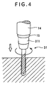
- a hole before threading is machined on the object to be machined (see Fig. 4 ) and, subsequently, the drill 31 is detached from the holder 15 and the tap 32 is attached for threading (see Fig. 5 ) to form the threaded hole 100.
- the form of the threaded hole 100 is measured to obtain respective parameters a to d.
- the thread form measuring sensor 33 is attached to the holder 15 and the measuring sensor 33 is moved to right above the threaded hole 100. Thereafter, the measuring sensor 33 is lowered to insert the stylus 40 into the threaded hole 100. Subsequently, the measuring sensor 33 is moved horizontally, i.e. in a direction for the contact portion 42A of the stylus 40 touches the inner circumference of the threaded hole 100 so that the center line C of the connector 53 is located on an outer side than the inner circumference of the threaded hole 100. Accordingly, the contact portion 42A of the stylus 40 touches the inner circumference of the threaded hole 100.
- the measuring sensor 33 is moved upward, and the elastic deformation of the connector 53 in accordance with the displacement of the stylus 40 can be continuously detected by the displacement sensor 70, thus measuring form of the inner circumference of the threaded hole 100. Accordingly, thread pitch a, effective thread portion length b, incomplete thread portion c and threaded hole depth d can be measured.
- the threaded hole 100 and the thread form measuring sensor 33 are relatively moved along the axial direction (vertical direction) of the threaded hole 100 while the contact portion 42A of the stylus 40 keeps in contact with the surface of the threaded hole 100. Then, the contact portion 42A of the stylus 40 scans the inner circumference of the threaded hole 100 and displaces in a direction approximately orthogonal with the relative movement, so that the stylus attachment 51 of the adaptor 50 attached with the stylus 40 displaces in the same direction. On the other hand, since the body attachment 52 of the adaptor 50 is attached to the body 60 relatively moving along the axial direction of the threaded hole 100, the displacement direction becomes solely the relative movement direction.
- the connector 53 connecting the stylus attachment 51 and the body attachment 52 elastically deforms. Accordingly, the displacement of the stylus attachment 51, i.e. the displacement of the contact portion 42A of the stylus 40 can be shown as the elastic deformation of the connector 53.
- Continuous inner circumference form data of the threaded hole 100 can be collected within a short time by continuously detecting the elastic deformation of the connector 53 with the deformation sensor 70.
- the stylus 40 includes the first arm 41 attached to the stylus attachment 51 and extending along the axial direction of the threaded hole 100, and the second arm 42 extending approximately orthogonal with the first arm 41 and having the contact portion 42A, the stylus 40 can be easily inserted into the threaded hole 100 and the contact portion 42A can be securely brought into contact with the inner circumference of the threaded hole 100.
- the contact portion 42A of the stylus 40 is disposed on the center line C of the connector 53 approximately parallel with the relative movement direction. Accordingly, the friction force applied to the contact portion 42A in axial direction of the connector 53 is not shown as an elastic deformation in a direction approximately orthogonal with the relative movement direction of the connector 53. Accordingly, the influence of the friction force fluctuating according to surface roughness of the workpiece etc. can be eliminated, so that only the displacement in the direction approximately orthogonal with the relative movement of the stylus 40 can be reflected on the elastic deformation of the connector 53.
- the deformation sensor 70 for detecting the elastic deformation of the connector 53 includes the strain gauge 71 attached to the connector 53, so that inexpensive arrangement is possible.
- the stylus 40 is formed by the piano wire, the stylus 40 can be arranged inexpensive and any desired form of stylus 40 corresponding to the thread form can be easily formed by bending the piano wire.
- the tap 32 is attached to the holder 15 to form the threaded hole 100 on the workpiece, the tap 32 is detached from the holder 15 and the thread form measuring sensor 33 is attached for measuring the form of the threaded hole 100.
- the workpiece (object to be machined) is not necessary to be moved. Accordingly, the positioning and movement of the workpiece are not necessary for measurement, thus reducing measurement time.
- the sequential process for forming the threaded hole 100 on the workpiece can be conducted simultaneously with measuring the form of the threaded hole 100.
- machining of hole before threading of the threaded hole 100, threading and form-measuring of the threaded hole 100 can be conducted sequentially, so that machining time and measurement time can be reduced.
- the measuring sensor can be easily exchanged to sensors having appropriate form and size in accordance with the shape and size of the object to be measured (thread form).
- the structure of the thread form measuring instrument 1 is the same as in the above-described embodiment shown in Fig. 1 and description thereof is omitted.
- the contact pressure is controlled constant in scanning measurement of the thread form.
- the contact portion 42A of the stylus 40 is brought into contact with the inner circumference of the threaded hole 100.
- the contact portion 42A is pressed on the measurement surface of the workpiece to apply measurement pressure so that the output of the deformation sensor 70 becomes a constant value.
- the second slider 14 is raised to move the measuring sensor 33 upwardly along the measurement surface (thread) of the workpiece.
- the contact portion 42A displaces in accordance with the shape of the measurement surface of the workpiece (thread surface), the displacement of the contact portion 42A causing change in elastic deformation of the connector 53 and, as a result, changing output of the deformation sensor 70.
- the computer 20 reads the change in the output, and controls the first slider 13 to move the measurement sensor 33 in right and left direction (vertical direction relative to the measurement surface of the workpiece) so that the output becomes the constant value.
- the output of the displacement sensor 70 returns to the constant value and the measurement pressure also returns to the constant value.
- the measuring sensor 33 is moved in the right and left direction by controlling the first slider 13 so that the deformation sensor 70 stays constant, the measuring sensor 33 is moved upward along the measurement surface of the workpiece and the displacement of the first slider 13 and the second slider 14 is continuously read from a scale (not shown) as a coordinates value data and is registered and stored in the computer 20. Since the contact portion 42A of the measuring sensor 33 moves in accordance with the form of the measurement surface as in known scanning probe, the coordinates data represents the form of the measurement surface. Accordingly, the parameters of the thread such as the thread pitch a, effective thread portion length b, incomplete thread portion c and threaded hole depth d can be obtained.
- the first slider 13 is simultaneously moved in right and left direction so that the output of the deformation sensor 70 becomes constant.
- the connector 53 connecting the stylus attachment 51 and the body attachment 52 elastically deforms to alter the output value of the deformation sensor 70, causing right and left movement of the measuring sensor 33.
- the displacement of the contact portion 42A of the stylus 40 (vertical direction, right and left direction) can be represented as a displacement of the first slider 13 and the second slider 14. Accordingly, by continuously detecting and collecting the displacements as a coordinates value data, the continuous data of the inner circumference of the threaded hole 100 can be collected within a short time.
- the rotation error (so-called circular error: position error caused in measurement surface direction in accordance with the separation of the contact portion from a reference surface of workpiece) occurred in rotary movement of the stylus 40 is not caused, thus enhancing accuracy of the measurement.
- the measurement is conducted by parallel movement not by rotary movement, the measurement range is not limited, so that a wide area can be measured with high accuracy. Further, continuous scanning measurement is possible.
- the present invention is not restricted to the above respective embodiments, but includes modifications and improvements as long as an object of the present invention can be achieved.
- the stylus 40 itself is not elastically deformed in the above embodiments, the same measurement performance can be obtained even when the rigidity of the stylus 40 is low and the elastic deformation is caused in measuring the thread form.
- the displacement of the contact portion 42A can be obtained by calibrating the detected value of the strain gauge 71.
- the thread form measuring sensor 33 and the threaded hole 100 are relatively moved in axial direction of the threaded hole 100 by the movement of the thread form measuring sensor 33 in the above-described embodiments, the threaded hole as the workpiece may be moved or, alternatively, both of the thread form measuring sensor and the threaded hole may be moved, as long as the thread form measuring sensor and the threaded hole are relatively moved.
- the threaded hole 100 is specifically taken as a thread to be measured, the thread according to the present invention is not restricted to the threaded hole by may be a threaded shaft.
- the workpiece is not restricted to the thread but may be a general two-dimensional workpiece or a three-dimensional workpiece.
Description
- The present invention relates to a form measuring sensor and a form measuring instrument. More specifically, it relates to a form measuring sensor and a form measuring instrument for measuring a form of a workpiece by touching a stylus on a surface of a thread.
- There are various shapes of workpiece to be measured. Among the workpiece, a thread of a threaded workpiece (threaded hole = internal thread, threaded shaft = external thread) has parameters (characteristic value) for defining characteristic thereof. Such parameters include thread pitch a, effective thread portion length b, incomplete thread portion c, threaded hole depth d etc. as shown in threaded
hole 100 ofFig. 7 . A coordinates measuring machine is used for measuring respective parameters a to d of the threadedhole 100. - In order to measure the thread by the coordinates measuring machine, a touch signal probe or a scanning probe can be used.
- When a touch signal probe is used, the contact portion of the touch signal probe is brought into contact with the surface of the thread and the coordinates value at the time is read. The thread form is measured by obtaining coordinates value at a desired plurality of points by repeating the above operation.
- On the other hand, when the scanning probe is used, the scanning probe and the thread are relatively moved while a contact portion of the scanning probe keeps in contact with the thread surface with a constant measurement force. The thread form is measured by continuously collecting the coordinates value of the contact portion.
- However, following disadvantages occur in measuring the thread form using the above-described coordinates measuring machine.
- When the touch signal probe is used to measure the workpiece, the touch signal probe has to touch the thread surface at respective points. Accordingly, for measuring the respective parameters of, for instance, the threaded
hole 100, the data have to be continuously collected by multi-point measurement, so that considerable time is required for measurement. - On the other hand, when the scanning probe is used to measure the workpiece, since contact and separation are not required between the probe and the thread surface for respective points unlike the measurement using the touch signal probe, the data can be continuously collected within a short period of time. However, the scanning probe having a mechanism for continuously detecting the coordinates value of the contact portion while keeping the contact portion in contact with the thread surface is expensive in itself.
-
US-A-5,263,375 discloses a contact detector with first and second strain generative bodies arranged between a stylus and a housing and connected to a transducer for outputting an electronic signal corresponding to the mechanical deformations produced by the first and second strain generative bodies when a force is applied to the stylus. - An object of the present invention is to provide a form measuring sensor and a form measuring instrument capable of continuously collecting workpiece surface form data within a short time and capable of being inexpensively constructed.
- A form measuring sensor according to an aspect of the present invention includes: a stylus having a contact portion to be in contact with a workpiece surface at a first end; and
a body for holding the stylus through an adaptor, the adaptor including a stylus attachment for a second end of the stylus to be attached, a body attachment to be attached to the body and an elastically deformable connector for connecting the stylus attachment and the body attachment,
wherein the connector elastically deforms to allow a displacement of the stylus and the stylus attachment relative to the body attachment in accordance with a configuration of the surface of the workpiece, and
wherein a deformation sensor for detecting the elastic deformation of the connector is provided, characterised in that: - the stylus is formed in approximate L-shape and includes a first arm extending along the surface of the workpiece with an end attached to the stylus attachment, and a second arm extending substantially orthogonal with the other end of the first arm and having the contact portion at an end thereof; and in that
- the contact portion of the stylus is disposed on a center line of the connector approximately parallel to the relative movement direction when the workpiece and the body are relatively moved along the surface of the workpiece while the contact portion of the stylus keeps in contact with the surface of the workpiece.
- In the present invention, the workpiece and the form measuring sensor are relatively moved in surface direction of the workpiece while the contact portion of the stylus keeps in contact with the surface of the workpiece. Then, the contact portion of the stylus scans the inner circumference of the workpiece and displaces in a direction approximately orthogonal with the relative movement, so that the stylus attachment of the adaptor attached with the stylus displaces in the same direction . On the other hand, since the body attachment of the adaptor is attached to the body relatively moving in the surface direction of the workpiece, the displacement direction becomes solely the relative movement direction. In other words, since the stylus attachment of the adaptor displaces approximately orthogonal with the relative movement direction and the body attachment does not displace relative to the body, the connector connecting the stylus attachment and the body attachment elastically deforms. Accordingly, the displacement of the stylus attachment, i.e. the displacement of the contact portion of the stylus can be represented by the elastic deformation of the connector. Continuous inner circumference form data of the workpiece can be collected within a short time by continuously detecting the elastic deformation of the connector with the deformation sensor.
- The surface form of the workpiece is measured by detecting the elastic deformation of the connector which allows the displacement of the stylus by elastic deformation thereof, i.e. brings the stylus into contact with the workpiece with a constant measuring force. In other words, since the contact portion is brought into contact with the workpiece surface with a constant force and the displacement of the contact portion is continuously detected by the connector, the mechanism can be arranged simpler and more inexpensive than a scanning probe.
- According to the invention, the stylus is formed in approximate L-shape and include a first arm extending along the surface of the workpiece with an end attached to the stylus attachment, and a second arm extending substantially orthogonal with the other end of the first arm and having the contact portion at an end thereof.
- Since the stylus includes the first arm attached to the stylus attachment and extending along the surface of the workpiece, and the second arm extending approximately orthogonal with the first arm and having the contact portion, the stylus can be easily inserted into the threaded hole, and the contact portion can be securely brought into contact with the thread bottom of the threaded hole.
- According to the present invention, when the workpiece and the body are relatively moved along the surface of the workpiece while the contact portion of the stylus keeps in contact with the surface of the workpiece, and the contact portion of the stylus is disposed on a center line of the connector approximately parallel to the relative movement direction.
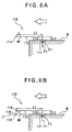
- When the contact portion of the stylus scans the surface of the workpiece, some friction force is ordinarily generated between the contact portion and the workpiece surface. The friction force fluctuates according to measurement force applied to the contact portion and surface roughness of the workpiece etc. Specifically, when
Fig. 6(A) is taken as an example, thestylus 110 is moved in a direction indicated by outlined arrow in the figure while an end of an approximately L-shaped stylus 110, i.e. acontact portion 111 keeps in contact with the surface of a workpiece W. At this time, measurement force Fv and friction force Ff are applied on thecontact portion 111. When the length of thefirst arm 112 is L1 and the length of thesecond arm 113 is L2, a moment M1 applied to theother end 114 of thestylus 110. - When the connector of the adaptor is located on the
other end 114 of thestylus 110, the moment M1 is applied on the connector to cause elastic deformation of the connector. The elastic deformation of the connector varies in accordance with surface form of the workpiece W. Accordingly, the surface configuration of the workpiece W can be detected by detecting and continuously recording the variation of the elastic deformation. In other words, the variation of the elastic deformation of the connector is preferably caused only by the displacement of theconnector 111. However, as shown inFig. 6(A) , when the connector is at the other end 114 (on the first arm 112) being offset from thecontact portion 111 by the length L2, the moment generated by fluctuating friction force Ff causes change in the elastic deformation of the connector. - Accordingly, in the present invention, as shown in
Fig. 6(B) for instance, thecontact portion 111 of thestylus 110 is disposed on a center line C of theconnector 115 approximately parallel with the relative movement direction (in an outlined arrow direction in the figure). Specifically, the connector is not disposed on theother end 114 of thestylus 110, but theconnector 115 is disposed at a position offset from the other end 114 (the first arm 112) by the length L2. Incidentally, theconnector 115 may be disposed by connecting theother end 114 and theconnector 115 with amember 116 shown in double-dotted line in the figure (astylus attachment 116, for instance). Accordingly, since the friction force Ff applied to thecontact portion 111 when thestylus 110 is moved in the direction of the outlined arrow in the figure is approximately parallel with the center line C of theconnector 115, the moment caused by the friction force Ff is not applied on theconnector 115, so that moment M2 applied to theconnector 115 can be represented as follows:
- Accordingly, the friction force Ff applied to the
contact portion 111 is not shown in the elastic deformation in a direction approximately orthogonal with the relative movement of theconnector 15. Therefore, the influence of the friction force Ff fluctuating on account of surface roughness etc. can be eliminated, so that the displacement of the stylus in a direction approximately orthogonal with the relative movement can be reflected on the elastic deformation of theconnector 115. - In the form measuring sensor according to the present invention, the deformation sensor may preferably include a strain gauge attached to the connector.
- According to the above arrangement, since the deformation sensor for detecting the elastic deformation of the connector includes the strain gauge attached to the connector, inexpensive construction is possible.
- In the form measuring sensor according to the present invention, the stylus may preferably be formed of a piano wire.
- According to the above arrangement, since the stylus is made of piano wire, inexpensive construction is possible. Further, any desired form of stylus corresponding to the form of the workpiece can be easily formed by bending the piano wire.
- A form measuring instrument according to another aspect of the present invention has a form measuring sensor according to the aforesaid aspect of the present invention; the instrument including: a holder for the form measuring sensor to be detachably attached; a relative movement mechanism for relatively moving the holder and the workpiece surface along a surface of the workpiece; and a controller for controlling the relative movement mechanism.
- According to the above arrangement, the same function and effect as in the form measuring sensor of the aforesaid aspect of the present invention can be obtained. Specifically, since the contact portion contacts the workpiece surface with a constant force by the connector and the displacement of the connector is continuously detected by the connector, the continuous workpiece surface form data can be collected within a short time and inexpensive construction is possible.
- The form measuring sensor according to the present invention may preferably be a sensor for measuring a thread form. By applying the present invention, a profile of a workpiece with relatively large undulations can be measured.
- The form measuring instrument according to the present invention may preferably has the workpiece form sensor for measuring the thread form. Accordingly, the form measuring sensor can be easily exchanged with a sensor having appropriate size corresponding to the magnitude of the undulations of the thread.
- In the form measuring instrument, a machining tool for threading the workpiece to form the thread may preferably be detachably attached to the holder.
- According to the present arrangement, after, for instance, the tap is attached to the holder to form the threaded hole on the workpiece, the tap is detached from the holder and the form measuring sensor can be attached to measure the form of the workpiece.
- Since thread cutting for finishing the workpiece into a final shape and measurement required after the thread cutting are conducted with the same instrument, the workpiece (object to be machined) is not necessary to be moved. Accordingly, positioning and position-calculation of the workpiece is not necessary, so that measurement time can be reduced.
- In the form measuring instrument according to the present invention, a machining tool for forming a hole before threading of the thread on the workpiece may preferably be detachably attached to the holder.
- According to the above arrangement, measurement of the workpiece form and formation of the workpiece on the object to be machined can be conducted simultaneously with measuring the workpiece form. In other words, the process from machining the hole before threading of the workpiece, to threading and measurement of the workpiece form can be conducted sequentially, so that machining and measurement time can be reduced.
- The relative movement mechanism preferably comprises a surface-direction relative movement mechanism for relatively moving the holder and the workpiece surface along a surface of the workpiece; and a crosswise relative movement mechanism for relatively moving the holder and the workpiece surface in a direction intersecting the workpiece; the controller being adapted to control the surface-direction relative movement mechanism and the crosswise relative movement mechanism, the controller controlling the crosswise relative movement mechanism so that an output of the deformation sensor becomes always constant.
- According to the above arrangement, when the output of the deformation sensor changes in accordance with change in the attitude of the stylus on account of irregularities in measuring the workpiece surface by a scanning measurement, the controller controls the crosswise relative movement mechanism to change the stylus crosswise position relative to the workpiece surface, so that the attitude of the stylus relative to the workpiece surface stays always constant. Accordingly, great range of crosswise measurement can be obtained while avoiding circular error of the stylus.
- In the above form measuring instrument, the form measuring sensor may preferably be a sensor for measuring a thread form. Accordingly, the form measuring sensor can be easily exchanged with a sensor of appropriate size in accordance with undulations of the thread form.
-
-
Fig. 1 is a general illustration showing a form measuring instrument according to an embodiment of the present invention; -
Fig. 2 is a partially crosscut side elevation showing the form measuring instrument according to the aforesaid embodiment; -
Fig. 3 is an enlarged perspective view showing an adapter of the form measuring instrument according to the aforesaid embodiment; -
Fig. 4 is an illustration showing a function of the form measuring instrument according to the aforesaid embodiment; -
Fig. 5 is an illustration showing another function of the form measuring instrument according to the aforesaid embodiment; -
Figs. 6(A) and 6(B) are schematic views showing a function of the present invention; and -
Fig. 7 is a schematic view showing a threaded hole as an object to be measured. - An embodiment of the present invention will be described below with reference to attached drawings.
- The present embodiment is for scanning measurement of thread configuration of a thread (threaded hole 100) formed on an object to be machined. A thread form measuring instrument 1 is used as a form measuring instrument according to the present invention.
-
Fig. 1 shows a general illustration of thread form measuring instrument according to an embodiment of the present invention. The thread form measuring instrument 1 has ainstrument body 10 for forming the threadedhole 100 on the object and for measuring form of the formed threadedhole 100, acomputer 20 for controlling theinstrument body 10 and atoolbox 30 accommodatingvarious tools 31 to 33 required for machining and measuring the threadedhole 100. - The
instrument body 10 is provided with a table 11 for the workpiece (object to be machined) to be mounted, and aportal frame 12 provided upright on the table 11. Theportal frame 12 has a pair ofcolumn 12 provided upright on the table 11. Abridge 122 stretches between thecolumns 121 substantially horizontally and afirst slider 13 is provided to thebridge 122 slidably along the longitudinal direction. - A
second slider 14 is elevatably provided to thefirst slider 13. A rotational shaft (not shown) having aholder 15 at a lower end thereof is rotatably provided to thesecond slider 14. Various tools such as adrill 31, atap 32 and a threadform measuring sensor 33 are detachably attached to theholder 15. - The
holder 15 is capable of horizontal and vertical movement by thefirst slider 13 and thesecond slider 14 and is rotatable by the rotational shaft. Though not shown, thefirst slider 13, thesecond slider 14 and the rotational shaft are driven by a driving system, which is controlled by thecomputer 20 as a controller. Specifically, the respective driving systems are actuated by entering coordinates value or rotation frequency into thecomputer 20, so that therespective tools 31 to 33 attached to theholder 15 conduct various movements (horizontal and vertical movement and rotation). Incidentally, the relative movement mechanism includes thesecond slider 14 and a driving system for vertically moving thesecond slider 14. - The
tools 31 to 33 accommodated in thetoolbox 30 include thedrill 31 as a machining tool for forming a hole before threading of the threadedhole 100 on the object to be machined, thetap 32 as a machining tool for thread-cutting (threading) the hole before threading, and the threadform measuring sensor 33 for measuring the form of the formed threadedhole 100. Thedrill 31 and thetap 32 are those usually used for machining threaded holes, which are respectively provided withattachments 311 and 312 to be attached to theholder 15. - As enlarged in
Fig. 2 , the threadform measuring sensor 33 includes astylus 40 having acontact portion 42A to be in contact with an inner circumference of the threadedhole 100 on an end thereof, and abody 60 for holding thestylus 40 through anadaptor 50. - The
stylus 40 is formed in L-shape by bending a piano wire. Specifically, thestylus 40 has afirst arm 41 with an end attached to theadaptor 50 and asecond arm 42 extending substantially orthogonal with the other end of thefirst arm 41 and having acontact portion 42A at an end thereof. - As enlarged in
Fig. 3 , theadaptor 50 has astylus attachment 51 to which thefirst arm 41 of thestylus 40 is attached, abody attachment 52 to be attached to thebody 60 and an elasticallydeformable connector 53 for connecting thestylus attachment 51 and thebody attachment 52. Thestylus attachment 51, thebody attachment 52 and theconnector 53 are integrally formed of, for instance, duralumin. - The
first arm 41 of thestylus 40 is secured to thestylus attachment 51. Though not shown, thestylus 40 is secured to thestylus attachment 51 by inserting thefirst arm 41 into an insert hole formed on thestylus attachment 51 and fixing with fixture such as a thread or by bonding or welding. - On the other hand, the
body attachment 52 is also attached to thebody 60 by the fixture such as a thread or by bonding or welding. - The
connector 53 is formed in a thin plate capable of elastically deformation in front and back directions, the opposing pair of peripheral ends being respectively connected to thestylus attachment 51 and thebody attachment 52. - A center line C of the connector 53 (center line C extending from the
stylus attachment 51 to the body attachment 52) and thefirst arm 41 of thestylus 40 are disposed in parallel with a predetermined interval. The direction of the predetermined interval is front and back direction of theconnector 53. On the other hand, thesecond arm 42 is substantially parallel to the back and front direction of theconnector 53, and thecontact portion 42A is disposed on the center line C of theconnector 53. - The
connector 53 allows displacement of thestylus 40 and thestylus attachment 51 relative to the body attachment 52 (displacement in the front and back direction of the connector 53) by elastic deformation thereof in the front and back direction. - A
deformation sensor 70 for detecting elastic deformation of theconnector 53 is provided to the threadform measuring sensor 33. - The
displacement sensor 70 detects the elastic deformation, i.e. bending strain, in the front and back direction of theconnector 53 of theadaptor 50, which includes a pair ofstrain gauges 71 respectively attached to the front and back sides of theconnector 53. Though not shown, the strain gauges 71 are integrated to a bridge circuit by being connected with a lead wire, so that the elastic deformation in the front and back direction of theconnector 53 can be detected. - Next, a function of the present embodiment will be described below.
- Initially, a
thread hole 100 is formed on the object to be machined. - Specifically, after mounting and positioning the object to be machined on the table 11, the
drill 31 is attached to theholder 15. Thetools 31 to 33 may be attached and exchanged manually or, alternatively, automatically with a tool exchanger ordinarily used for machining center etc. After thedrill 31 is attached to theholder 15, a hole before threading is machined on the object to be machined (seeFig. 4 ) and, subsequently, thedrill 31 is detached from theholder 15 and thetap 32 is attached for threading (seeFig. 5 ) to form the threadedhole 100. - Next, after the threaded
hole 100 is formed, the form of the threadedhole 100 is measured to obtain respective parameters a to d. - Specifically, the thread
form measuring sensor 33 is attached to theholder 15 and the measuringsensor 33 is moved to right above the threadedhole 100. Thereafter, the measuringsensor 33 is lowered to insert thestylus 40 into the threadedhole 100. Subsequently, the measuringsensor 33 is moved horizontally, i.e. in a direction for thecontact portion 42A of thestylus 40 touches the inner circumference of the threadedhole 100 so that the center line C of theconnector 53 is located on an outer side than the inner circumference of the threadedhole 100. Accordingly, thecontact portion 42A of thestylus 40 touches the inner circumference of the threadedhole 100. The measuringsensor 33 is moved upward, and the elastic deformation of theconnector 53 in accordance with the displacement of thestylus 40 can be continuously detected by thedisplacement sensor 70, thus measuring form of the inner circumference of the threadedhole 100. Accordingly, thread pitch a, effective thread portion length b, incomplete thread portion c and threaded hole depth d can be measured. - According to the above-described embodiment, following effects can be obtained.
- In the present embodiment, the threaded
hole 100 and the threadform measuring sensor 33 are relatively moved along the axial direction (vertical direction) of the threadedhole 100 while thecontact portion 42A of thestylus 40 keeps in contact with the surface of the threadedhole 100. Then, thecontact portion 42A of thestylus 40 scans the inner circumference of the threadedhole 100 and displaces in a direction approximately orthogonal with the relative movement, so that thestylus attachment 51 of theadaptor 50 attached with thestylus 40 displaces in the same direction. On the other hand, since thebody attachment 52 of theadaptor 50 is attached to thebody 60 relatively moving along the axial direction of the threadedhole 100, the displacement direction becomes solely the relative movement direction. In other words, since thestylus attachment 51 of theadaptor 50 displaces in approximately orthogonal with the relative movement direction and thebody attachment 52 does not displace relative to thebody 60, theconnector 53 connecting thestylus attachment 51 and thebody attachment 52 elastically deforms. Accordingly, the displacement of thestylus attachment 51, i.e. the displacement of thecontact portion 42A of thestylus 40 can be shown as the elastic deformation of theconnector 53. Continuous inner circumference form data of the threadedhole 100 can be collected within a short time by continuously detecting the elastic deformation of theconnector 53 with thedeformation sensor 70. - Since the
stylus 40 includes thefirst arm 41 attached to thestylus attachment 51 and extending along the axial direction of the threadedhole 100, and thesecond arm 42 extending approximately orthogonal with thefirst arm 41 and having thecontact portion 42A, thestylus 40 can be easily inserted into the threadedhole 100 and thecontact portion 42A can be securely brought into contact with the inner circumference of the threadedhole 100. - The
contact portion 42A of thestylus 40 is disposed on the center line C of theconnector 53 approximately parallel with the relative movement direction. Accordingly, the friction force applied to thecontact portion 42A in axial direction of theconnector 53 is not shown as an elastic deformation in a direction approximately orthogonal with the relative movement direction of theconnector 53. Accordingly, the influence of the friction force fluctuating according to surface roughness of the workpiece etc. can be eliminated, so that only the displacement in the direction approximately orthogonal with the relative movement of thestylus 40 can be reflected on the elastic deformation of theconnector 53. - The
deformation sensor 70 for detecting the elastic deformation of theconnector 53 includes thestrain gauge 71 attached to theconnector 53, so that inexpensive arrangement is possible. - Since the
stylus 40 is formed by the piano wire, thestylus 40 can be arranged inexpensive and any desired form ofstylus 40 corresponding to the thread form can be easily formed by bending the piano wire. - Initially, after the
tap 32 is attached to theholder 15 to form the threadedhole 100 on the workpiece, thetap 32 is detached from theholder 15 and the threadform measuring sensor 33 is attached for measuring the form of the threadedhole 100. - Since the threading for finishing the threaded
hole 100 in the final machined shape and the measurement required after the threading are conducted with the same instrument, the workpiece (object to be machined) is not necessary to be moved. Accordingly, the positioning and movement of the workpiece are not necessary for measurement, thus reducing measurement time. - The sequential process for forming the threaded
hole 100 on the workpiece can be conducted simultaneously with measuring the form of the threadedhole 100. In other words, machining of hole before threading of the threadedhole 100, threading and form-measuring of the threadedhole 100 can be conducted sequentially, so that machining time and measurement time can be reduced. - The measuring sensor can be easily exchanged to sensors having appropriate form and size in accordance with the shape and size of the object to be measured (thread form).
- Next, another embodiment of the present invention will be described below.
- In the present embodiment, the structure of the thread form measuring instrument 1 is the same as in the above-described embodiment shown in
Fig. 1 and description thereof is omitted. In the present embodiment, the contact pressure is controlled constant in scanning measurement of the thread form. - Specifically, also in the present embodiment, after the measuring
sensor 33 is lowered to insert thestylus 40 into the threadedhole 100, thecontact portion 42A of thestylus 40 is brought into contact with the inner circumference of the threadedhole 100. - Subsequently, the
contact portion 42A is pressed on the measurement surface of the workpiece to apply measurement pressure so that the output of thedeformation sensor 70 becomes a constant value. In the condition, thesecond slider 14 is raised to move the measuringsensor 33 upwardly along the measurement surface (thread) of the workpiece. At this time, thecontact portion 42A displaces in accordance with the shape of the measurement surface of the workpiece (thread surface), the displacement of thecontact portion 42A causing change in elastic deformation of theconnector 53 and, as a result, changing output of thedeformation sensor 70. Thecomputer 20 reads the change in the output, and controls thefirst slider 13 to move themeasurement sensor 33 in right and left direction (vertical direction relative to the measurement surface of the workpiece) so that the output becomes the constant value. As a result, the output of thedisplacement sensor 70 returns to the constant value and the measurement pressure also returns to the constant value. In this manner, while the measuringsensor 33 is moved in the right and left direction by controlling thefirst slider 13 so that thedeformation sensor 70 stays constant, the measuringsensor 33 is moved upward along the measurement surface of the workpiece and the displacement of thefirst slider 13 and thesecond slider 14 is continuously read from a scale (not shown) as a coordinates value data and is registered and stored in thecomputer 20. Since thecontact portion 42A of the measuringsensor 33 moves in accordance with the form of the measurement surface as in known scanning probe, the coordinates data represents the form of the measurement surface. Accordingly, the parameters of the thread such as the thread pitch a, effective thread portion length b, incomplete thread portion c and threaded hole depth d can be obtained. - According to the present embodiment, following effects can be obtained.
- When the threaded
hole 100 and the threadform measuring sensor 33 relatively move along the axial direction of the threaded hole 100 (vertical direction) while thecontact portion 42A of thestylus 40 keeps in contact with the surface of the threadedhole 100, thefirst slider 13 is simultaneously moved in right and left direction so that the output of thedeformation sensor 70 becomes constant. In other words, when thecontact portion 42A displaces in a direction (right and left direction = direction orthogonal with the measurement surface) approximately orthogonal with the relative movement direction (vertical direction) in accordance with the form of the surface of the threadedhole 100, theconnector 53 connecting thestylus attachment 51 and thebody attachment 52 elastically deforms to alter the output value of thedeformation sensor 70, causing right and left movement of the measuringsensor 33. The displacement of thecontact portion 42A of the stylus 40 (vertical direction, right and left direction) can be represented as a displacement of thefirst slider 13 and thesecond slider 14. Accordingly, by continuously detecting and collecting the displacements as a coordinates value data, the continuous data of the inner circumference of the threadedhole 100 can be collected within a short time. At this time, since thestylus 40 moves parallel relative to the measurement surface, the rotation error (so-called circular error: position error caused in measurement surface direction in accordance with the separation of the contact portion from a reference surface of workpiece) occurred in rotary movement of thestylus 40 is not caused, thus enhancing accuracy of the measurement. Further, since the measurement is conducted by parallel movement not by rotary movement, the measurement range is not limited, so that a wide area can be measured with high accuracy. Further, continuous scanning measurement is possible. - Incidentally, the present invention is not restricted to the above respective embodiments, but includes modifications and improvements as long as an object of the present invention can be achieved.
- For instance, though the
stylus 40 itself is not elastically deformed in the above embodiments, the same measurement performance can be obtained even when the rigidity of thestylus 40 is low and the elastic deformation is caused in measuring the thread form. - Specifically, when both of the
stylus 40 and theconnector 53 elastically deform by the displacement of thecontact portion 42A in a direction orthogonal with the center line C, though the displacement of thecontact portion 42A in the direction orthogonal with the center line C cannot be accurately measured, the displacement is absorbed by the elastic deformation of both of thestylus 40 and theconnector 53. Accordingly, whether thecontact portion 42A is displaced in the direction orthogonal with the center line C or not, or the magnitude of the displacement can be detected by thestrain gauge 71. Since the parameters of the threadedhole 100 to be measured is, as shown inFig. 7 , the various parameters a to d as shown inFig. 7 , the parameters a to d can be accurately measured by detecting the existence of the displacement of thecontact portion 42A in the direction orthogonal with the center line C and magnitude thereof. - By measuring the elastic deformation ratio of both of the
stylus 40 and theconnector 53 in advance, the displacement of thecontact portion 42A can be obtained by calibrating the detected value of thestrain gauge 71. - Though the thread
form measuring sensor 33 and the threadedhole 100 are relatively moved in axial direction of the threadedhole 100 by the movement of the threadform measuring sensor 33 in the above-described embodiments, the threaded hole as the workpiece may be moved or, alternatively, both of the thread form measuring sensor and the threaded hole may be moved, as long as the thread form measuring sensor and the threaded hole are relatively moved. - Though the threaded
hole 100 is specifically taken as a thread to be measured, the thread according to the present invention is not restricted to the threaded hole by may be a threaded shaft. - The workpiece is not restricted to the thread but may be a general two-dimensional workpiece or a three-dimensional workpiece.
Claims (5)
- A form measuring sensor (33) comprising:a stylus (40) having a contact portion (42A) to be in contact with a workpiece surface at a first end; anda body (60) for holding the stylus (40) through an adaptor (50), the adaptor (50) including a stylus attachment (51) for a second end of the stylus (40) to be attached, a body attachment (52) to be attached to the body (60) and an elastically deformable connector (53) for connecting the stylus attachment (51) and the body attachment (52),wherein the connector (53) elastically deforms to allow a displacement of the stylus (40) and the stylus attachment (51) relative to the body attachment (52) in accordance with a configuration of the surface of the workpiece, andwherein a deformation sensor (70) for detecting the elastic deformation of the connector (53) is provided, characterised in that:the stylus is formed in approximate L-shape and includes a first arm (41) extending along the surface of the workpiece with an end attached to the stylus attachment (51), and a second arm (42) extending substantially orthogonal with the other end of the first arm (41) and having the contact portion (42A) at an end thereof; and in thatthe contact portion (42A) of the stylus (40) is disposed on a center line of the connector (53) approximately parallel to the relative movement direction when the workpiece and the body (60) are relatively moved along the surface of the workpiece while the contact portion (42A) of the stylus (40) keeps in contact with the surface of the workpiece.
- The form measuring sensor according to claim 1, wherein the deformation sensor (70) includes a strain gauge (71) attached to the connector (53).
- The form measuring sensor according to claim 1 or claim 2, wherein the stylus (40) is formed of a piano wire.
- A form measuring instrument having a form measuring sensor according to any one of claims 1 to 3, comprising:a holder (15) for the form measuring sensor (33) to be detachably attached;a relative movement mechanism (13, 14) for relatively moving the holder (15) and the workpiece surface along a surface of the workpiece; anda controller (20) for controlling the relative movement mechanism (13, 14).
- A form measuring instrument according to claim 4, wherein the relative movement mechanism comprises:a surface-direction relative movement mechanism for relatively moving the holder (15) and the workpiece surface along a surface of the workpiece; anda crosswise relative movement mechanism for relatively moving the holder (15) and the workpiece surface in a direction intersecting the workpiece; andthe controller (20) being adapted to control the crosswise relative movement mechanism so that an output of the deformation sensor (70) becomes always constant.
Applications Claiming Priority (2)
| Application Number | Priority Date | Filing Date | Title |
|---|---|---|---|
| JP2000132361 | 2000-05-01 | ||
| JP2000132361 | 2000-05-01 |
Publications (3)
| Publication Number | Publication Date |
|---|---|
| EP1152209A2 EP1152209A2 (en) | 2001-11-07 |
| EP1152209A3 EP1152209A3 (en) | 2003-05-07 |
| EP1152209B1 true EP1152209B1 (en) | 2009-06-03 |
Family
ID=18641080
Family Applications (1)
| Application Number | Title | Priority Date | Filing Date |
|---|---|---|---|
| EP01303858A Expired - Lifetime EP1152209B1 (en) | 2000-05-01 | 2001-04-27 | Form measuring sensor and form measuring instrument |
Country Status (4)
| Country | Link |
|---|---|
| US (1) | US6543150B2 (en) |
| EP (1) | EP1152209B1 (en) |
| CN (1) | CN1181309C (en) |
| DE (1) | DE60138852D1 (en) |
Families Citing this family (29)
| Publication number | Priority date | Publication date | Assignee | Title |
|---|---|---|---|---|
| AU2002311510A1 (en) * | 2001-06-12 | 2002-12-23 | Hexagon Metrology Ab | A communication method and common control bus interconnecting a controller and a precision measurement assembly |
| JP2004264272A (en) * | 2003-02-28 | 2004-09-24 | Oht Inc | Electric conductor inspecting device and electric conductor inspection method |
| CA2423395A1 (en) * | 2003-03-25 | 2004-09-25 | Fathi Saigh | Level monitoring sensor apparatus, solid structure sensor apparatus, and pendulum sensor apparatus |
| US6772527B1 (en) * | 2003-04-09 | 2004-08-10 | Renishaw Plc | Modular measurement device |
| US7376261B2 (en) * | 2003-11-25 | 2008-05-20 | Mitutoyo Corporation | Surface scan measuring device and method of forming compensation table for scanning probe |
| GB0518078D0 (en) * | 2005-09-06 | 2005-10-12 | Renishaw Plc | Signal transmission system |
| JP4828974B2 (en) * | 2006-03-16 | 2011-11-30 | 株式会社ミツトヨ | Screw measuring method, screw measuring probe, and screw measuring device using the same |
| CN100455982C (en) * | 2006-11-27 | 2009-01-28 | 联合汽车电子有限公司 | Locating hole checking device |
| US20090019715A1 (en) * | 2007-07-19 | 2009-01-22 | Productivity Inc. | Integrated gauging and robotic apparatus and method |
| JP5451180B2 (en) * | 2009-05-22 | 2014-03-26 | 株式会社ミツトヨ | Roundness measuring machine |
| WO2011003944A1 (en) * | 2009-07-10 | 2011-01-13 | Marposs Societa' Per Azioni | Checking device, modular system and relative fulcrum device |
| IT1399152B1 (en) * | 2009-09-25 | 2013-04-11 | Marposs Spa | CONTROL DEVICE AND ITS FULCRO DEVICE |
| JP5318967B2 (en) | 2009-12-21 | 2013-10-16 | 東芝三菱電機産業システム株式会社 | Air gap measuring device |
| DE102009060784A1 (en) * | 2009-12-22 | 2011-06-30 | Carl Zeiss 3D Automation GmbH, 73447 | Stylus and probe for a coordinate measuring machine |
| CN102162726B (en) * | 2010-12-13 | 2012-06-27 | 亿和精密工业(苏州)有限公司 | Device for automatically detecting workpiece |
| FR2972526B1 (en) * | 2011-03-10 | 2016-05-20 | Commissariat Energie Atomique | DEVICE FOR MEASURING THE SURFACE CONDITION OF A SURFACE |
| WO2012157126A1 (en) * | 2011-05-19 | 2012-11-22 | 株式会社牧野フライス製作所 | Machine tool having workpiece measuring function |
| JP6168946B2 (en) * | 2013-09-24 | 2017-07-26 | 株式会社ミツトヨ | Feed mechanism, shape measuring machine |
| CN104913719B (en) * | 2014-12-29 | 2018-03-23 | 湖南吉利汽车部件有限公司 | One kind welding burr detection fingerstall and detection method |
| EP3472556B1 (en) * | 2016-06-15 | 2023-08-23 | Hexagon Metrology, Inc. | Cmm apparatus for identifying and confirming the stylus |
| EP3479054B1 (en) * | 2016-07-01 | 2024-01-03 | Mitutoyo Corporation | Power transfer configuration for supplying power to a detachable probe for a coordinate measurement machine |
| US11035657B2 (en) * | 2016-11-07 | 2021-06-15 | Dai-Ichi Sokuhan Works Co. | Threaded-hole inspection device |
| JP6368986B1 (en) | 2017-03-27 | 2018-08-08 | 株式会社東京精密 | Detector, surface texture measuring instrument, and roundness measuring instrument |
| US10697750B2 (en) * | 2018-05-04 | 2020-06-30 | Ford Motor Company | Device and thread gauging method for ensuring spark plug orientation |
| US10252350B1 (en) | 2018-06-17 | 2019-04-09 | Arevo, Inc. | Fiducial marks for articles of manufacture with non-trivial dimensional variations |
| CN110487201B (en) * | 2019-07-26 | 2021-08-31 | 广东天机工业智能系统有限公司 | Side hole depth measuring device |
| CN110390380A (en) * | 2019-08-20 | 2019-10-29 | 昆山艾伯格机器人科技有限公司 | A kind of thread detecting device and method |
| DE102020108162A1 (en) | 2020-03-25 | 2021-09-30 | Carl Zeiss Industrielle Messtechnik Gmbh | Stylus extension for a measuring head, coordinate measuring machine and method for measuring coordinates or properties of a workpiece |
| US11524410B2 (en) * | 2020-06-12 | 2022-12-13 | Hexagon Metrology, Inc. | Robotic alignment method for workpiece measuring systems |
Family Cites Families (24)
| Publication number | Priority date | Publication date | Assignee | Title |
|---|---|---|---|---|
| US3512261A (en) * | 1968-08-05 | 1970-05-19 | Gerard J Viollet | Machinist's locating tool |
| GB2009409A (en) * | 1977-12-03 | 1979-06-13 | Beecham Group Ltd | Measuring and recording surface profile |
| US4377911A (en) * | 1981-02-18 | 1983-03-29 | Mitutoyo Mfg. Co., Ltd. | Contour measuring instrument |
| JPS57141038A (en) * | 1981-02-24 | 1982-09-01 | Toshiba Corp | Recording and reproducing device |
| US4574625A (en) * | 1983-04-12 | 1986-03-11 | Federal Products Corporation | Surface finish, displacement and contour scanner |
| US4567672A (en) * | 1983-06-16 | 1986-02-04 | Mitutoyo Mfg. Co., Ltd. | Coordinate measuring instrument |
| US4784539A (en) * | 1987-05-18 | 1988-11-15 | Manuflex Corporation | Tool communications method |
| US4778313A (en) * | 1987-05-18 | 1988-10-18 | Manuflex Corp. | Intelligent tool system |
| US5263375A (en) | 1987-09-18 | 1993-11-23 | Wacoh Corporation | Contact detector using resistance elements and its application |
| DE68916463T2 (en) * | 1988-04-12 | 1994-11-17 | Renishaw Plc | Signal transmission system for machine tools, inspection machines and the like. |
| US5327657A (en) * | 1991-07-11 | 1994-07-12 | Renishaw Metrology Ltd. | Touch probe |
| DE4130990A1 (en) * | 1991-09-18 | 1993-03-25 | Zeiss Carl Fa | PROTECTIVE DEVICE FOR LONG-EXTENDED MACHINE PARTS |
| EP0566719B1 (en) * | 1991-11-09 | 1997-02-19 | Renishaw Metrology Limited | Touch probe |
| JP2809295B2 (en) * | 1992-03-26 | 1998-10-08 | 株式会社東京精密 | Coordinate measuring machine and its measuring method |
| DE4327250C5 (en) * | 1992-09-25 | 2008-11-20 | Carl Zeiss Industrielle Messtechnik Gmbh | Method for measuring coordinates on workpieces |
| US5611147A (en) * | 1993-02-23 | 1997-03-18 | Faro Technologies, Inc. | Three dimensional coordinate measuring apparatus |
| DE4410195C1 (en) * | 1994-03-24 | 1995-11-09 | Zeiss Carl Jena Gmbh | Method and arrangement for measuring tapered threads |
| GB9612383D0 (en) * | 1995-12-07 | 1996-08-14 | Rank Taylor Hobson Ltd | Surface form measurement |
| SE9600078L (en) * | 1996-01-09 | 1997-05-12 | Johansson Ab C E | Device for dimensional determination of three-dimensional measuring objects |
| JP3285320B2 (en) * | 1997-02-17 | 2002-05-27 | 株式会社ミツトヨ | Touch signal probe |
| NL1005718C2 (en) * | 1997-04-03 | 1998-10-07 | Ir Reginald Galestien | Method for accurately measuring threads and related geometries. |
| US6430828B1 (en) * | 1998-04-17 | 2002-08-13 | Electronic Measuring Devices, Inc. | Coordinate positioning apparatus with indexable stylus, components thereof, and method of using it |
| JP3992853B2 (en) * | 1998-09-30 | 2007-10-17 | 株式会社ミツトヨ | Surface following type measuring machine |
| JP2000292156A (en) | 1999-04-09 | 2000-10-20 | Tokyo Seimitsu Co Ltd | Method for measuring effective screw hole depth |
-
2001
- 2001-04-27 EP EP01303858A patent/EP1152209B1/en not_active Expired - Lifetime
- 2001-04-27 US US09/842,919 patent/US6543150B2/en not_active Expired - Lifetime
- 2001-04-27 DE DE60138852T patent/DE60138852D1/en not_active Expired - Lifetime
- 2001-04-30 CN CNB011176091A patent/CN1181309C/en not_active Expired - Lifetime
Also Published As
| Publication number | Publication date |
|---|---|
| EP1152209A2 (en) | 2001-11-07 |
| US6543150B2 (en) | 2003-04-08 |
| EP1152209A3 (en) | 2003-05-07 |
| CN1181309C (en) | 2004-12-22 |
| CN1321871A (en) | 2001-11-14 |
| DE60138852D1 (en) | 2009-07-16 |
| US20010034948A1 (en) | 2001-11-01 |
Similar Documents
| Publication | Publication Date | Title |
|---|---|---|
| EP1152209B1 (en) | Form measuring sensor and form measuring instrument | |
| EP1650527B1 (en) | Apparatus for measuring the surface roughness or the contour of an object | |
| US7660688B2 (en) | Surface-profile measuring instrument | |
| JP2988588B2 (en) | Position measuring device | |
| EP0373644A1 (en) | Three-dimensional displacement gauge | |
| JP3396409B2 (en) | Method and apparatus for measuring shape and size of work | |
| JP6104557B2 (en) | Surface roughness measuring unit, 3D measuring device | |
| JPS63134151A (en) | Device and method of inspecting position of setting of tool | |
| CA1336532C (en) | Probe motion guiding device, position sensing apparatus and position sensing method | |
| JP3784273B2 (en) | Work shape measuring sensor and work shape measuring device | |
| EP2085739B1 (en) | Probe straightness measuring method | |
| JP2005121370A (en) | Surface shape measuring apparatus and method | |
| EP2244053A1 (en) | Coordinate Measuring Machine | |
| JP6738661B2 (en) | Industrial machinery | |
| JP3126327B2 (en) | Method and apparatus for measuring shape and size of work in machine tool | |
| WO2019155698A1 (en) | Surface shape measurement device | |
| JP5219480B2 (en) | Workpiece machining method | |
| JP4783056B2 (en) | Probe approach direction setting method, shape measuring device program, and storage medium | |
| JP3939805B2 (en) | NC machine tool workpiece measurement method | |
| JP2019158385A (en) | measuring device | |
| JP2002039743A (en) | Measuring instrument | |
| CN216977853U (en) | Height gauge with increased measuring range | |
| US20230280145A1 (en) | Measurement method | |
| JP2019141971A (en) | robot | |
| JPS6318684B2 (en) |
Legal Events
| Date | Code | Title | Description |
|---|---|---|---|
| PUAI | Public reference made under article 153(3) epc to a published international application that has entered the european phase |
Free format text: ORIGINAL CODE: 0009012 |
|
| AK | Designated contracting states |
Kind code of ref document: A2 Designated state(s): AT BE CH CY DE DK ES FI FR GB GR IE IT LI LU MC NL PT SE TR |
|
| AX | Request for extension of the european patent |
Free format text: AL;LT;LV;MK;RO;SI |
|
| PUAL | Search report despatched |
Free format text: ORIGINAL CODE: 0009013 |
|
| AK | Designated contracting states |
Designated state(s): AT BE CH CY DE DK ES FI FR GB GR IE IT LI LU MC NL PT SE TR |
|
| AX | Request for extension of the european patent |
Extension state: AL LT LV MK RO SI |
|
| RIC1 | Information provided on ipc code assigned before grant |
Ipc: 7G 01B 7/012 A Ipc: 7G 01B 5/20 B |
|
| 17P | Request for examination filed |
Effective date: 20031024 |
|
| AKX | Designation fees paid |
Designated state(s): DE FR GB IT |
|
| 17Q | First examination report despatched |
Effective date: 20080702 |
|
| GRAC | Information related to communication of intention to grant a patent modified |
Free format text: ORIGINAL CODE: EPIDOSCIGR1 |
|
| GRAP | Despatch of communication of intention to grant a patent |
Free format text: ORIGINAL CODE: EPIDOSNIGR1 |
|
| GRAS | Grant fee paid |
Free format text: ORIGINAL CODE: EPIDOSNIGR3 |
|
| GRAA | (expected) grant |
Free format text: ORIGINAL CODE: 0009210 |
|
| AK | Designated contracting states |
Kind code of ref document: B1 Designated state(s): DE FR GB IT |
|
| REG | Reference to a national code |
Ref country code: GB Ref legal event code: FG4D |
|
| REF | Corresponds to: |
Ref document number: 60138852 Country of ref document: DE Date of ref document: 20090716 Kind code of ref document: P |
|
| PLBE | No opposition filed within time limit |
Free format text: ORIGINAL CODE: 0009261 |
|
| STAA | Information on the status of an ep patent application or granted ep patent |
Free format text: STATUS: NO OPPOSITION FILED WITHIN TIME LIMIT |
|
| 26N | No opposition filed |
Effective date: 20100304 |
|
| REG | Reference to a national code |
Ref country code: FR Ref legal event code: PLFP Year of fee payment: 16 |
|
| REG | Reference to a national code |
Ref country code: FR Ref legal event code: PLFP Year of fee payment: 17 |
|
| REG | Reference to a national code |
Ref country code: FR Ref legal event code: PLFP Year of fee payment: 18 |
|
| REG | Reference to a national code |
Ref country code: DE Ref legal event code: R082 Ref document number: 60138852 Country of ref document: DE Representative=s name: KEIL & SCHAAFHAUSEN PATENTANWAELTE PARTGMBB, DE Ref country code: DE Ref legal event code: R082 Ref document number: 60138852 Country of ref document: DE Representative=s name: KEIL & SCHAAFHAUSEN PATENT- UND RECHTSANWAELTE, DE |
|
| PGFP | Annual fee paid to national office [announced via postgrant information from national office to epo] |
Ref country code: FR Payment date: 20200420 Year of fee payment: 20 Ref country code: DE Payment date: 20200420 Year of fee payment: 20 |
|
| PGFP | Annual fee paid to national office [announced via postgrant information from national office to epo] |
Ref country code: IT Payment date: 20200428 Year of fee payment: 20 Ref country code: GB Payment date: 20200427 Year of fee payment: 20 |
|
| REG | Reference to a national code |
Ref country code: DE Ref legal event code: R071 Ref document number: 60138852 Country of ref document: DE |
|
| REG | Reference to a national code |
Ref country code: GB Ref legal event code: PE20 Expiry date: 20210426 |
|
| PG25 | Lapsed in a contracting state [announced via postgrant information from national office to epo] |
Ref country code: GB Free format text: LAPSE BECAUSE OF EXPIRATION OF PROTECTION Effective date: 20210426 |