EP1645784A2 - Ölfilter für automatisches Getriebe - Google Patents
Ölfilter für automatisches Getriebe Download PDFInfo
- Publication number
- EP1645784A2 EP1645784A2 EP05021660A EP05021660A EP1645784A2 EP 1645784 A2 EP1645784 A2 EP 1645784A2 EP 05021660 A EP05021660 A EP 05021660A EP 05021660 A EP05021660 A EP 05021660A EP 1645784 A2 EP1645784 A2 EP 1645784A2
- Authority
- EP
- European Patent Office
- Prior art keywords
- oil
- area
- inlet port
- filter
- space section
- Prior art date
- Legal status (The legal status is an assumption and is not a legal conclusion. Google has not performed a legal analysis and makes no representation as to the accuracy of the status listed.)
- Granted
Links
- 230000005540 biological transmission Effects 0.000 title claims description 11
- 238000010586 diagram Methods 0.000 description 3
- 230000002411 adverse Effects 0.000 description 2
- 239000000428 dust Substances 0.000 description 2
- 230000003247 decreasing effect Effects 0.000 description 1
- 230000004048 modification Effects 0.000 description 1
- 238000012986 modification Methods 0.000 description 1
- 230000000149 penetrating effect Effects 0.000 description 1
Images





Classifications
-
- B—PERFORMING OPERATIONS; TRANSPORTING
- B01—PHYSICAL OR CHEMICAL PROCESSES OR APPARATUS IN GENERAL
- B01D—SEPARATION
- B01D35/00—Filtering devices having features not specifically covered by groups B01D24/00 - B01D33/00, or for applications not specifically covered by groups B01D24/00 - B01D33/00; Auxiliary devices for filtration; Filter housing constructions
-
- F—MECHANICAL ENGINEERING; LIGHTING; HEATING; WEAPONS; BLASTING
- F16—ENGINEERING ELEMENTS AND UNITS; GENERAL MEASURES FOR PRODUCING AND MAINTAINING EFFECTIVE FUNCTIONING OF MACHINES OR INSTALLATIONS; THERMAL INSULATION IN GENERAL
- F16H—GEARING
- F16H57/00—General details of gearing
- F16H57/04—Features relating to lubrication or cooling or heating
- F16H57/0402—Cleaning of lubricants, e.g. filters or magnets
- F16H57/0404—Lubricant filters
-
- F—MECHANICAL ENGINEERING; LIGHTING; HEATING; WEAPONS; BLASTING
- F16—ENGINEERING ELEMENTS AND UNITS; GENERAL MEASURES FOR PRODUCING AND MAINTAINING EFFECTIVE FUNCTIONING OF MACHINES OR INSTALLATIONS; THERMAL INSULATION IN GENERAL
- F16H—GEARING
- F16H57/00—General details of gearing
- F16H57/02—Gearboxes; Mounting gearing therein
- F16H57/027—Gearboxes; Mounting gearing therein characterised by means for venting gearboxes, e.g. air breathers
Definitions
- the present invention relates to an oil strainer for an automatic transmission, which is provided in a hydraulic system for supplying a working oil to the automatic transmission in order to remove foreign matters, such as dust contained in the oil.
- Japanese Patent Application First Publication No. 2004-28145 describes an oil strainer including a body, a filter disposed at a central portion of the body, an inlet port formed at a lower wall of the body, and an outlet port formed at an upper wall of the body.
- the outlet port is communicated with an oil pump.
- the oil pump is driven to suck an oil stored within an oil pan into the oil strainer through the inlet port.
- the oil sucked is filtered through the filter and then discharged from the outlet port and fed to parts of an automatic transmission via hydraulic passages.
- FIG. 3 illustrates a conventional oil strainer in vertical cross-section.
- conventional oil strainer 10 includes body 11 and filter 12 that is arranged within body 11.
- Inlet port 13 is provided on lower wall 11A of body 11.
- Outlet port 14 is provided on upper wall 11B of body 11.
- Outlet port 14 is connected to an oil pump, not shown, and a hydraulic passage, not shown, connected with the oil pump.
- An oil within an oil pan, not shown, is sucked into body 11 from inlet port 13 and filtered through filter 12 and then discharged from outlet port 14 to the oil pump.
- the inventors of the present invention have found that there is a relationship between a volume of the air accumulated in a space below a filter within an oil strainer and a hydraulic pressure rise time during which a hydraulic pressure is varied from a minimum value, for instance, 0, at which an operation of the oil pump starts with engine startup, to a desired value.
- the present invention has been made. That is, it has been found that the above-described problem of the conventional art can be solved by reducing a volume of the space below the filter within the oil strainer with maintaining a performance of the oil strainer.
- An object of the present invention is to provide an oil strainer capable of effectively suppressing entrainment of air into a working oil in an automatic transmission while maintaining a performance of the oil strainer.
- an oil strainer for an automatic transmission comprising:
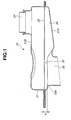
- FIG. 1 is a vertical cross-sectional view of an oil strainer of a first embodiment according to the present invention.
- FIG. 2 is a plan view of an inside bottom of a lower wall of the oil strainer shown in FIG. 1.
- FIG. 3 is a view similar to FIG. 1, but shows a conventional oil strainer.
- FIG. 4 is a plan view of an inside bottom of a lower wall of the oil strainer shown in FIG. 3.
- FIG. 5 is a diagram illustrating a relationship between a volume of air accumulated in an oil strainer and a hydraulic pressure rise time.
- FIG. 6 is a schematic diagram illustrating a predictive pattern of an oil flow in an oil strainer.
- FIG. 7 is a schematic diagram illustrating an actual pattern of an oil flow in an oil strainer.
- FIG. 8 is a view similar to FIG. 1, but shows a second embodiment of the oil strainer of the present invention.
- FIG. 9 is a plan view of an inside bottom of a lower wall of the oil strainer shown in FIG. 8.
- FIG. 1 is a vertical cross-section of an oil strainer according to a first embodiment of the present invention.
- oil strainer 20 includes body 21 and filer 22 substantially horizontally disposed within body 21.
- Body 21 includes lower wall 21A and upper wall 21B which are disposed on lower and upper sides of oil strainer 20 in a vertical direction, i.e., an up-and-down direction of oil strainer 20, respectively.
- Filter 22 is in the form of a mesh and arranged to divide an inside space of body 21 into a lower space section and an upper space section. Filter 22 may be placed in a substantially central position within body 21 in the vertical direction of oil strainer 20.
- Oil strainer 20 further includes inlet port 23 provided on lower wall 21A and outlet port 24 provided on upper wall 21B.
- Inlet port 23 is provided in area 25 of lower wall 21A and communicated with the lower space section.
- inlet port 23 is defined by a tubular wall portion which is integrally formed with lower wall 21A and downwardly extends from inlet port periphery 23A toward an oil pan, not shown.
- Outlet port 24 is provided on upper wall 21B and communicated with the upper space section. Outlet port 24 is arranged in non-alignment with inlet port 23 in the vertical direction of oil strainer 20.
- Outlet port 24 is defined by a cylindrical wall portion that is integrally formed with upper wall 21B and upwardly extends. Outlet port 24 is connected to an oil pump, not shown.
- an oil pump not shown.
- a working oil stored within the oil pan is sucked and introduced into inlet port 23 and flows in the lower space section below filter 22.
- the working oil is filtered through filter 22 and discharged from outlet port 24, and then fed to the oil pump and supplied to parts of an automatic transmission via a hydraulic passage that is connected with the oil pump.
- FIG. 2 is a plan view of an inside bottom of lower wall 21A of oil strainer 20 without filter 22.
- lower wall 21A includes two areas 25 and 26, namely, area 25 in which inlet port periphery 23A is disposed, and area 26 separate from area 25.
- Area 25 substantially horizontally extends along inlet port periphery 23A defining an upper opening of inlet port 23 which is exposed to the lower space section.
- Area 26 includes an inner region substantially vertically aligned with a lower opening of outlet port 24 which is exposed to the upper space section, and an outer region that surrounds the inner region and extends outside the inner region.
- a boundary between area 25 and area 26 extends substantially perpendicular to a direction of streamline of the oil which flows in the lower space section from inlet port 23 toward area 26.
- Lower wall 21A is configured such that vertical distance X 2 between filter 22 and lower wall 21A in area 25 is smaller than a vertical distance between filter 22 and lower wall 21A in area 26 as shown in FIG. 1.
- the vertical distances between filter 22 and lower wall 21A in respective areas 25 and 26 extend between a lower surface of filter 22 and an upper surface of lower wall 21A in respective areas 25 and 26 in the vertical direction of oil strainer 20.
- a depth from filter 22 to lower wall 21A in area 25 is smaller than a depth from filter 22 to lower wall 21A in area 26.
- area 25 acts as a small depth area of lower wall 21A
- area 26 acts as a large depth area of lower wall 21A.
- FIGS. 3 and 4 are a vertical cross-section of a conventional oil strainer and a plan view of an inside bottom of lower wall 11A of conventional oil strainer 10, respectively.
- conventional oil strainer 10 includes body 11 and filer 12 disposed within body 11.
- Body 11 includes lower wall 11A and upper wall 11B which are disposed on lower and upper sides of conventional oil strainer 10 in a vertical direction, i.e., an up-and-down direction of conventional oil strainer 10.
- Filter 12 is in the form of a mesh and substantially horizontally arranged in a substantially central position within body 11 so as to divide an inside space of body 11 into a lower space section and an upper space section.
- Conventional oil strainer 10 further includes inlet port 13 provided on lower wall 11A and outlet port 14 provided on upper wall 11B. Inlet port 13 is communicated with the lower space section.
- Inlet port 13 is defined by a tubular wall portion which is integrally formed with lower wall 11A and downwardly extends from inlet port periphery 13A toward an oil pan, not shown.
- Outlet port 14 is provided on upper wall 11B and communicated with the upper space section.
- Outlet port 14 is arranged in non-alignment with inlet port 13 in the vertical direction of conventional oil strainer 10.
- Outlet port 14 is defined by a cylindrical wall portion that is integrally formed with upper wall 21B and upwardly extends. Outlet port 14 is connected to an oil pump, not shown.
- conventional oil strainer 10 when an operation of the oil pump starts, a working oil stored within the oil pan is sucked from inlet port 13, filtered through filter 12 and discharged from outlet port 14. The working oil discharged is fed to the oil pump and then supplied to parts of an automatic transmission via a hydraulic passage connected with the oil pump.
- FIG. 5 illustrates a relationship between a volume of the air accumulated in the lower space section below the filter in the conventional oil strainer and a hydraulic pressure rise time during which a hydraulic pressure is varied from a minimum value when an operation of the oil pump starts with engine startup, to a desired value.
- the hydraulic pressure rise time is increased.
- FIG. 6 illustrates a predictive pattern of a flow of an oil flowing in conventional oil strainer 10 as shown in FIG. 3 when starting an operation of the oil pump under a relatively low oil temperature condition.
- FIG. 7 illustrates an actual pattern of the oil flow flowing in conventional oil strainer 10 when starting an operation of the oil pump under the same oil temperature condition.
- the oil flow is predicted such that the oil flowing from inlet port 13 into the lower space section passes and penetrates through a substantially entire area of the respective lower and upper surfaces of filter 12 and then flows out from outlet port 14 as indicated by arrows.
- the oil flowing from inlet port 13 is prevented from readily passing and penetrating through filter 12, and allowed to flow beneath along the lower surface of filter 12.
- the oil is then allowed to pass and penetrate through the local area of the respective lower and upper surfaces of filter 12 by a suction force, i.e., by a negative pressure caused by operation of the oil pump.
- oil strainer 20 of the first embodiment can reduce an amount of the air accumulated in the lower space section below filter 22 during a period in which an operation of the oil pump is stopped. This results in effectively preventing the accumulated air from being fed to the oil pump when starting the operation of the oil pump. Therefore, oil strainer 20 of the first embodiment serves for suppressing the increase in hydraulic pressure rise time which will occur in the conventional oil strainer when starting the operation of the oil pump, particularly, under the relatively low oil temperature condition. Further, oil strainer 20 can maintain a good performance without adversely affecting flow resistance of the oil flowing in the lower space section of oil strainer 20.
- FIGS. 8 and 9 are a vertical cross-section of a conventional oil strainer and a plan view of an inside bottom of lower wall 11A of conventional oil strainer 10, respectively.
- oil strainer 30 includes body 31 and filer 32 disposed within body 31.
- Body 31 includes lower wall 31A and upper wall 31B which are disposed on lower and upper sides of oil strainer 30 in a vertical direction, i.e., an up-and-down direction of oil strainer 30.
- Filter 32 is in the form of a mesh and substantially horizontally arranged within body 31 such that an inside space of body 31 is divided into a lower space section defined between filter 32 and lower wall 31A and an upper space section defined between filter 32 and upper wall 31B.
- Oil strainer 30 further includes inlet port 33 provided on lower wall 31A and outlet port 34 provided on upper wall 31B.
- Inlet port 33 is provided in area 35 of lower wall 31A and communicated with the lower space section.
- inlet port 33 is defined by a tubular wall portion which is integrally formed with lower wall 31A and downwardly extends from inlet port periphery 33A toward an oil pan, not shown.
- Outlet port 34 is provided on upper wall 31B and communicated with the upper space section.
- Outlet port 34 is arranged in non-alignment with inlet port 33 in the vertical direction of oil strainer 30.
- Outlet port 34 is defined by a cylindrical wall portion that is integrally formed with upper wall 31B and upwardly extends. Outlet port 34 is connected to an oil pump, not shown. Similar to the first embodiment, when an operation of the oil pump starts with engine startup, a working oil stored within the oil pan is sucked and introduced into inlet port 33 and flows in the lower space section below filter 32. The working oil is filtered through filter 32 and discharged from outlet port 34, and then fed to the oil pump and supplied to parts of an automatic transmission via a hydraulic passage that is connected with the oil pump.
- lower wall 31A includes area 35 in which inlet port periphery 33A is disposed, and area 36 separate from area 35.
- Area 35 substantially horizontally extends along inlet port periphery 33A defining an upper opening of inlet port 33 which is exposed to the lower space section.
- area 36 has an elongated rectangular shape in plan view as shown in FIG. 9.
- Area 36 includes inner region 37A substantially vertically aligned with a lower opening of outlet port 34 which is exposed to the upper space section, and outer region 37B that surrounds inner region 37A and extends outside inner region 37A to a side periphery of lower wall 31A.
- Outer region 37B extends along a direction of streamline of the oil that flows in the lower space section from inlet port 33 toward inner region 37A of area 36.
- Outer region 37B includes a portion that extends between inlet port periphery 33A and inner region 37A along the direction of streamline of the oil that flows in the lower space section from inlet port 33 toward inner region 37A. That is, outer region 37B is located on a shortest route of streamline of the oil flowing in the lower space section from inlet port 33 toward inner region 37A.
- Area 35 includes a portion that extends along and adjacent to area 36 in parallel to the direction of streamline of the oil that flows in the lower space section from inlet port 33 toward inner region 37A of area 36.
- area 35 is increased in comparison to area 25 of lower wall 21A of oil strainer 20 of the first embodiment.
- Vertical distance X 2 between filter 32 and lower wall 31A in area 35 is smaller than a vertical distance between filter 32 and lower wall 31A in area 36.
- a vertical distance between filter 32 and lower wall 31A in area 36 is larger than vertical distance X 2 between filter 32 and lower wall 31A in area 35.
- the vertical distances between filter 32 and lower wall 31A in respective areas 35 and 36 extend between a lower surface of filter 32 and an upper surface of lower wall 31A in respective areas 35 and 36.
- oil strainer 30 of the second embodiment can further reduce an amount of the air accumulated in the lower space section below filter 32 in comparison to oil strainer 20 of the first embodiment.
- oil strainer 30 of the second embodiment can serve for more effectively preventing the accumulated air from being fed to an oil pump when the operation of the oil pump starts.
- oil strainer 30 of the second embodiment serves for further suppressing the increase in hydraulic pressure rise time which will occur in the conventional oil strainer when starting an oil pump. Further, oil strainer 30 of the second embodiment can maintain a smooth flow of the oil flowing in the lower space section.
Landscapes
- Engineering & Computer Science (AREA)
- General Engineering & Computer Science (AREA)
- Mechanical Engineering (AREA)
- Chemical & Material Sciences (AREA)
- Chemical Kinetics & Catalysis (AREA)
- General Details Of Gearings (AREA)
- Filtration Of Liquid (AREA)
Applications Claiming Priority (1)
| Application Number | Priority Date | Filing Date | Title |
|---|---|---|---|
| JP2004293741A JP4794842B2 (ja) | 2004-10-06 | 2004-10-06 | ストレーナ |
Publications (3)
| Publication Number | Publication Date |
|---|---|
| EP1645784A2 true EP1645784A2 (de) | 2006-04-12 |
| EP1645784A3 EP1645784A3 (de) | 2011-05-04 |
| EP1645784B1 EP1645784B1 (de) | 2012-06-27 |
Family
ID=35406155
Family Applications (1)
| Application Number | Title | Priority Date | Filing Date |
|---|---|---|---|
| EP05021660A Ceased EP1645784B1 (de) | 2004-10-06 | 2005-10-04 | Ölfilter für automatisches Getriebe |
Country Status (5)
| Country | Link |
|---|---|
| US (1) | US8157105B2 (de) |
| EP (1) | EP1645784B1 (de) |
| JP (1) | JP4794842B2 (de) |
| KR (1) | KR100648992B1 (de) |
| CN (1) | CN100406783C (de) |
Families Citing this family (11)
| Publication number | Priority date | Publication date | Assignee | Title |
|---|---|---|---|---|
| JP4475286B2 (ja) | 2007-04-02 | 2010-06-09 | トヨタ自動車株式会社 | 車両のオイルポンプ制御装置 |
| US7875171B2 (en) * | 2007-11-01 | 2011-01-25 | Ford Global Technologies, Llc | Suction filter for an automatic transmission |
| DE102008027662A1 (de) * | 2008-06-10 | 2009-12-17 | Ibs Filtran Kunststoff- / Metallerzeugnisse Gmbh | Ölwanne mit Ölfilter |
| JP5274435B2 (ja) * | 2009-11-26 | 2013-08-28 | ジヤトコ株式会社 | オイルストレーナにおけるエア溜まり防止構造 |
| CN103225685B (zh) * | 2013-05-21 | 2015-12-02 | 江苏科雷斯普能源科技股份有限公司 | 用于中小型风力发电机齿轮油箱的精密过滤器 |
| JP6302338B2 (ja) * | 2014-04-18 | 2018-03-28 | ダイキョーニシカワ株式会社 | オイルストレーナ |
| CN105782420A (zh) * | 2016-05-12 | 2016-07-20 | 华北电力大学(保定) | 一种面向风机齿轮箱的精滤系统、控制方法及控制系统 |
| CN106641677B (zh) * | 2016-10-31 | 2018-04-13 | 广州文冲船厂有限责任公司 | 一种紧凑型双联精油滤器 |
| CN110478955A (zh) * | 2019-07-12 | 2019-11-22 | 安徽省锦瑞汽车部件有限公司 | 一种新型吸入式滤油器 |
| US11028741B1 (en) * | 2020-08-24 | 2021-06-08 | Apq Development, Llc | Oil pick-up assembly |
| CN119053802A (zh) * | 2022-03-23 | 2024-11-29 | 加特可株式会社 | 动力传递装置以及液压装置 |
Citations (2)
| Publication number | Priority date | Publication date | Assignee | Title |
|---|---|---|---|---|
| JP2004028145A (ja) | 2002-06-21 | 2004-01-29 | Fuji Heavy Ind Ltd | 変速機のオイル供給装置 |
| JP2004293741A (ja) | 2003-03-28 | 2004-10-21 | Nissan Diesel Motor Co Ltd | アウターケーシング |
Family Cites Families (15)
| Publication number | Priority date | Publication date | Assignee | Title |
|---|---|---|---|---|
| US3056501A (en) * | 1959-08-03 | 1962-10-02 | Gen Motors Corp | Transmission oil filter assemblage |
| JPH0610644A (ja) * | 1992-06-24 | 1994-01-18 | Toyota Motor Corp | 内燃機関のオイルストレーナ |
| JPH10296015A (ja) * | 1997-04-22 | 1998-11-10 | Jatco Corp | オイルストレーナ |
| JP3540546B2 (ja) * | 1997-06-04 | 2004-07-07 | ジヤトコ株式会社 | 自動変速機の油圧制御装置 |
| JP2000070623A (ja) * | 1998-09-04 | 2000-03-07 | Nsk Warner Kk | 自動変速機用流体フィルタ装置 |
| USD420682S (en) * | 1999-03-16 | 2000-02-15 | Spx Corporation | Transmission filter assembly |
| JP2000279719A (ja) * | 1999-03-31 | 2000-10-10 | Piolax Inc | オイルストレーナ |
| WO2002046584A1 (de) * | 2000-12-08 | 2002-06-13 | Ibs Filtran Kunststoff-/Metallerzeugnisse Gmbh | Metallölwanne mit integriertem ölfilter |
| JP4317347B2 (ja) * | 2001-04-27 | 2009-08-19 | 日本バイリーン株式会社 | 自動変速機用オイルフィルタの濾過材 |
| US6835306B2 (en) * | 2001-07-06 | 2004-12-28 | Spx Corporation | Return-side filter for use in a vehicle transmission |
| US6911141B2 (en) * | 2001-09-26 | 2005-06-28 | Wix Filtration Corp. | Low waste liquid filter |
| JP3857196B2 (ja) * | 2002-07-12 | 2006-12-13 | 東洋▲ろ▼機製造株式会社 | トランスミッション流体用フィルタ |
| JP2004176809A (ja) * | 2002-11-27 | 2004-06-24 | Toyo Roki Mfg Co Ltd | 自動変速機用オイルフィルタ及びその製造方法 |
| JP2004340327A (ja) * | 2003-05-19 | 2004-12-02 | Nok Corp | オイルストレーナ |
| US20050139541A1 (en) * | 2003-12-30 | 2005-06-30 | Peet C. A. | Filter media supporting apparatus and method in an engine or transmission filter |
-
2004
- 2004-10-06 JP JP2004293741A patent/JP4794842B2/ja not_active Expired - Fee Related
-
2005
- 2005-09-08 KR KR1020050083486A patent/KR100648992B1/ko not_active Expired - Fee Related
- 2005-09-29 CN CN2005101069611A patent/CN100406783C/zh not_active Expired - Fee Related
- 2005-10-04 EP EP05021660A patent/EP1645784B1/de not_active Ceased
- 2005-10-05 US US11/242,893 patent/US8157105B2/en active Active
Patent Citations (2)
| Publication number | Priority date | Publication date | Assignee | Title |
|---|---|---|---|---|
| JP2004028145A (ja) | 2002-06-21 | 2004-01-29 | Fuji Heavy Ind Ltd | 変速機のオイル供給装置 |
| JP2004293741A (ja) | 2003-03-28 | 2004-10-21 | Nissan Diesel Motor Co Ltd | アウターケーシング |
Also Published As
| Publication number | Publication date |
|---|---|
| JP2006105294A (ja) | 2006-04-20 |
| CN1763401A (zh) | 2006-04-26 |
| KR20060051090A (ko) | 2006-05-19 |
| US8157105B2 (en) | 2012-04-17 |
| US20060070943A1 (en) | 2006-04-06 |
| JP4794842B2 (ja) | 2011-10-19 |
| EP1645784B1 (de) | 2012-06-27 |
| EP1645784A3 (de) | 2011-05-04 |
| KR100648992B1 (ko) | 2006-11-27 |
| CN100406783C (zh) | 2008-07-30 |
Similar Documents
| Publication | Publication Date | Title |
|---|---|---|
| US8157105B2 (en) | Oil strainer for automatic transmission | |
| US9353851B2 (en) | Oil strainer for vehicle transmission | |
| EP1887192B1 (de) | Dampf-Flüssigkeits-Separator | |
| JP5179871B2 (ja) | 変速機のオイルストレーナ | |
| JP2017145890A (ja) | ストレーナのエアー抜き構造 | |
| JP2019215028A (ja) | オイルストレーナ | |
| WO2012073724A1 (ja) | 車両用エンジンのオイルパン構造 | |
| CN215927506U (zh) | 机油集滤结构及发动机 | |
| JP6584790B2 (ja) | 車両用オイルストレーナ | |
| JPS5894671A (ja) | 自動変速機用ストレ−ナ装置 | |
| KR20090058114A (ko) | 오일 팬 | |
| US12188614B2 (en) | Strainer | |
| JPH0542813U (ja) | 自動変速装置用流体フイルタ | |
| JP2016183758A (ja) | オイル吸入装置 | |
| JP2019215027A (ja) | オイルストレーナ | |
| JP2019215031A (ja) | オイルストレーナ | |
| KR20070101726A (ko) | 자동변속기 오일필터 | |
| JP2006057556A (ja) | オイル循環機構 | |
| JP2019113113A (ja) | オイルストレーナ | |
| KR20200096665A (ko) | 공기 분리를 포함하는 흡입 필터 장치 | |
| JP4114413B2 (ja) | オイルパンの潤滑油循環構造 | |
| JP2009156411A (ja) | 自動変速機 | |
| JP2006329379A (ja) | ベルト式無段変速機 | |
| JP2015048735A (ja) | オイルパン | |
| JP2017044273A (ja) | 変速機 |
Legal Events
| Date | Code | Title | Description |
|---|---|---|---|
| PUAI | Public reference made under article 153(3) epc to a published international application that has entered the european phase |
Free format text: ORIGINAL CODE: 0009012 |
|
| 17P | Request for examination filed |
Effective date: 20051004 |
|
| AK | Designated contracting states |
Kind code of ref document: A2 Designated state(s): AT BE BG CH CY CZ DE DK EE ES FI FR GB GR HU IE IS IT LI LT LU LV MC NL PL PT RO SE SI SK TR |
|
| AX | Request for extension of the european patent |
Extension state: AL BA HR MK YU |
|
| PUAL | Search report despatched |
Free format text: ORIGINAL CODE: 0009013 |
|
| AK | Designated contracting states |
Kind code of ref document: A3 Designated state(s): AT BE BG CH CY CZ DE DK EE ES FI FR GB GR HU IE IS IT LI LT LU LV MC NL PL PT RO SE SI SK TR |
|
| AX | Request for extension of the european patent |
Extension state: AL BA HR MK YU |
|
| AKX | Designation fees paid |
Designated state(s): DE FR GB IT |
|
| GRAP | Despatch of communication of intention to grant a patent |
Free format text: ORIGINAL CODE: EPIDOSNIGR1 |
|
| RIN1 | Information on inventor provided before grant (corrected) |
Inventor name: HIROTSU, SHINGO, C/O JATCO LTD. Inventor name: HIRAOKA, YOUJI, C/O JATCO LTD. Inventor name: NISHIYAMA, HIROYUKI, C/O JATCO LTD. |
|
| GRAS | Grant fee paid |
Free format text: ORIGINAL CODE: EPIDOSNIGR3 |
|
| GRAA | (expected) grant |
Free format text: ORIGINAL CODE: 0009210 |
|
| AK | Designated contracting states |
Kind code of ref document: B1 Designated state(s): DE FR GB IT |
|
| REG | Reference to a national code |
Ref country code: GB Ref legal event code: FG4D |
|
| REG | Reference to a national code |
Ref country code: DE Ref legal event code: R096 Ref document number: 602005034913 Country of ref document: DE Effective date: 20120823 |
|
| PLBE | No opposition filed within time limit |
Free format text: ORIGINAL CODE: 0009261 |
|
| STAA | Information on the status of an ep patent application or granted ep patent |
Free format text: STATUS: NO OPPOSITION FILED WITHIN TIME LIMIT |
|
| 26N | No opposition filed |
Effective date: 20130328 |
|
| REG | Reference to a national code |
Ref country code: DE Ref legal event code: R097 Ref document number: 602005034913 Country of ref document: DE Effective date: 20130328 |
|
| REG | Reference to a national code |
Ref country code: DE Ref legal event code: R082 Ref document number: 602005034913 Country of ref document: DE Representative=s name: GRUENECKER, KINKELDEY, STOCKMAIR & SCHWANHAEUS, DE |
|
| REG | Reference to a national code |
Ref country code: GB Ref legal event code: 732E Free format text: REGISTERED BETWEEN 20140206 AND 20140212 |
|
| REG | Reference to a national code |
Ref country code: DE Ref legal event code: R082 Ref document number: 602005034913 Country of ref document: DE Representative=s name: GRUENECKER, KINKELDEY, STOCKMAIR & SCHWANHAEUS, DE Effective date: 20140124 Ref country code: DE Ref legal event code: R081 Ref document number: 602005034913 Country of ref document: DE Owner name: JATCO LTD, JP Free format text: FORMER OWNER: JATCO LTD, FUJI, JP Effective date: 20140124 Ref country code: DE Ref legal event code: R081 Ref document number: 602005034913 Country of ref document: DE Owner name: JATCO LTD, JP Free format text: FORMER OWNER: JATCO LTD, FUJI, JP Effective date: 20120629 Ref country code: DE Ref legal event code: R081 Ref document number: 602005034913 Country of ref document: DE Owner name: NISSAN MOTOR CO., LTD., JP Free format text: FORMER OWNER: JATCO LTD, FUJI, JP Effective date: 20140124 Ref country code: DE Ref legal event code: R081 Ref document number: 602005034913 Country of ref document: DE Owner name: NISSAN MOTOR CO., LTD., JP Free format text: FORMER OWNER: JATCO LTD, FUJI, JP Effective date: 20120629 Ref country code: DE Ref legal event code: R081 Ref document number: 602005034913 Country of ref document: DE Owner name: NISSAN MOTOR CO., LTD., YOKOHAMA-SHI, JP Free format text: FORMER OWNER: JATCO LTD, FUJI, SHIZUOKA, JP Effective date: 20120629 Ref country code: DE Ref legal event code: R081 Ref document number: 602005034913 Country of ref document: DE Owner name: JATCO LTD, FUJI, JP Free format text: FORMER OWNER: JATCO LTD, FUJI, SHIZUOKA, JP Effective date: 20140124 Ref country code: DE Ref legal event code: R081 Ref document number: 602005034913 Country of ref document: DE Owner name: NISSAN MOTOR CO., LTD., YOKOHAMA-SHI, JP Free format text: FORMER OWNER: JATCO LTD, FUJI, SHIZUOKA, JP Effective date: 20140124 Ref country code: DE Ref legal event code: R081 Ref document number: 602005034913 Country of ref document: DE Owner name: JATCO LTD, FUJI, JP Free format text: FORMER OWNER: JATCO LTD, FUJI, SHIZUOKA, JP Effective date: 20120629 Ref country code: DE Ref legal event code: R082 Ref document number: 602005034913 Country of ref document: DE Representative=s name: GRUENECKER PATENT- UND RECHTSANWAELTE PARTG MB, DE Effective date: 20140124 |
|
| REG | Reference to a national code |
Ref country code: FR Ref legal event code: TQ Owner name: JATCO LTD, JP Effective date: 20140217 Ref country code: FR Ref legal event code: TQ Owner name: NISSAN MOTOR CO., LTD, JP Effective date: 20140217 |
|
| REG | Reference to a national code |
Ref country code: FR Ref legal event code: PLFP Year of fee payment: 11 |
|
| REG | Reference to a national code |
Ref country code: FR Ref legal event code: PLFP Year of fee payment: 12 |
|
| REG | Reference to a national code |
Ref country code: FR Ref legal event code: PLFP Year of fee payment: 13 |
|
| REG | Reference to a national code |
Ref country code: FR Ref legal event code: PLFP Year of fee payment: 14 |
|
| PGFP | Annual fee paid to national office [announced via postgrant information from national office to epo] |
Ref country code: FR Payment date: 20180913 Year of fee payment: 14 |
|
| PGFP | Annual fee paid to national office [announced via postgrant information from national office to epo] |
Ref country code: DE Payment date: 20180918 Year of fee payment: 14 |
|
| PGFP | Annual fee paid to national office [announced via postgrant information from national office to epo] |
Ref country code: IT Payment date: 20181018 Year of fee payment: 14 Ref country code: GB Payment date: 20181003 Year of fee payment: 14 |
|
| REG | Reference to a national code |
Ref country code: DE Ref legal event code: R119 Ref document number: 602005034913 Country of ref document: DE |
|
| PG25 | Lapsed in a contracting state [announced via postgrant information from national office to epo] |
Ref country code: DE Free format text: LAPSE BECAUSE OF NON-PAYMENT OF DUE FEES Effective date: 20200501 |
|
| GBPC | Gb: european patent ceased through non-payment of renewal fee |
Effective date: 20191004 |
|
| PG25 | Lapsed in a contracting state [announced via postgrant information from national office to epo] |
Ref country code: IT Free format text: LAPSE BECAUSE OF NON-PAYMENT OF DUE FEES Effective date: 20191004 Ref country code: FR Free format text: LAPSE BECAUSE OF NON-PAYMENT OF DUE FEES Effective date: 20191031 Ref country code: GB Free format text: LAPSE BECAUSE OF NON-PAYMENT OF DUE FEES Effective date: 20191004 |