EP1632747A2 - Rotierendes Lasergerät - Google Patents
Rotierendes Lasergerät Download PDFInfo
- Publication number
- EP1632747A2 EP1632747A2 EP05090241A EP05090241A EP1632747A2 EP 1632747 A2 EP1632747 A2 EP 1632747A2 EP 05090241 A EP05090241 A EP 05090241A EP 05090241 A EP05090241 A EP 05090241A EP 1632747 A2 EP1632747 A2 EP 1632747A2
- Authority
- EP
- European Patent Office
- Prior art keywords
- plane
- fan
- rotary
- laser beam
- shaped
- Prior art date
- Legal status (The legal status is an assumption and is not a legal conclusion. Google has not performed a legal analysis and makes no representation as to the accuracy of the status listed.)
- Granted
Links
Images


Classifications
-
- G—PHYSICS
- G01—MEASURING; TESTING
- G01C—MEASURING DISTANCES, LEVELS OR BEARINGS; SURVEYING; NAVIGATION; GYROSCOPIC INSTRUMENTS; PHOTOGRAMMETRY OR VIDEOGRAMMETRY
- G01C15/00—Surveying instruments or accessories not provided for in groups G01C1/00 - G01C13/00
- G01C15/002—Active optical surveying means
- G01C15/004—Reference lines, planes or sectors
Definitions
- the present invention relates to a rotary laser apparatus which irradiates plural fan-shaped laser beams under rotation in directions orthogonal to a rotary axis and is used to measure an inclined angle and a height of a site relative to a plane orthogonal to the rotary axis through the irradiated light beams being received with a light-receiving sensor at a position distant from a light-projecting section.
- a rotary laser apparatus having a construction in which a laser beam source is provided directly on a rotary head (rotation-irradiating section) so as to be rotated relative to an apparatus body
- a cylindrical lens for converting a laser beam from the laser beam source into a fan-shaped laser beam is integrally provided at the rotary head, and the laser beam source and the cylindrical lens are integrally rotated in an identical direction together with the rotary head, so that fan-shaped laser beams are irradiated under rotation.
- a laser beam source is provided at an apparatus body
- a laser beam is led to a rotary head along a rotary axis, and biased in a direction orthogonal to the rotary axis.
- the thus biased laser beam is converted to fan-shaped laser beams with a cylindrical lens or a diffraction lattice, and irradiated under rotation in directions orthogonal to the rotary axis.
- a reflection mirror, a penta prism or an optical member equivalent thereto is used for biasing the laser beams.
- the rotary head In order to measure an inclined angle and a height of a site with reference to the rotating fan-shaped laser beams, the rotary head must be rotated at a constant and high speed, while the fan-shaped laser beams are not wobbled.
- the construction of the optical element can be simplified.
- the apparatus is configured such that the laser beam source is provided directly at the rotary head, deviations of the rotary axis makes direct influences upon the fan-shaped laser beams, so that this unfavorably directly affects detection accuracy of the light-receiving sensor.
- an electric power supply mechanism such as a slip ring must be provided in supplying electric power to the laser beam source provided at the rotary head, the electric power-supplying mechanism becomes generally complicated.
- the laser beam is led to the rotary head along the rotary axis, the laser beam is biased in a direction orthogonally to the rotary axis by means of the reflection mirror, the penta prism or the equivalent optical member, the thus biased laser beam is divided into at least two fan laser beams in specified directions, and the divided laser beams are irradiated through the rotary head portion.
- the penta prism or its equivalent optical member has a property of biasing the incident light beam to one orthogonal to the incident direction and emitting it, the rotary axis can be prevented from being wobbled.
- a first aspect of the present invention which has been accomplished in view of the above circumstances, is to provide a rotary laser apparatus that can easily divide the laser beam and prevent wobbling of the divided laser beams owing to vibration under rotation as much as possible.
- the rotary laser apparatus comprises a light-projection section configured to irradiate at least two fan-shaped beams extending in a fan-shaped form in a direction orthogonal to a rotary axis, said light-projecting section comprising a laser beam source for generating a laser beam in a direction of the rotary axis, and a rotation-irradiating section configured for irradiating the laser beam from the laser beam source in directions orthogonal to the rotary axis, said rotation-irradiating section comprising a plurality of penta prisms and a beam splitter, said plurality of the penta prisms being arranged in the direction of the rotary axis depending upon the number of said fan-shaped beams such that light-emitting directions of the respective penta prisms differ from each other or one another, and said beam splitter being configured to the laser beam as required the penta prism arranged above.
- the rotary laser apparatus further comprises cylindrical lenses provided at emitting planes of the respective penta prisms and each configured to convert the laser beam to the fan-shaped beam, and inclinations of the fan beams are set by arrangement of the respective cylindrical lens.
- the rotary laser apparatus further comprises a polarizing plate between the laser beam source and the rotation-irradiating section, said polarizing plate being configured to enter the laser beam from the laser beam source into the penta prism in the form of a circularly polarized light beam.
- the beam splitter is arranged between the adjacent penta prisms, and divide the laser beam from the laser beam source such that light amounts of the fan-shaped beams formed by the respective penta prisms are specified values.
- the rotary laser apparatus further comprises a rotary cylinder and wherein the penta prisms are arranged, inside the rotary cylinder, corresponding to the number of the fan-shaped beams, the rotary cylinder being supported by bearings at opposite ends thereof as viewed in the rotary axis, and wherein the fan-shaped beams are irradiated under rotation in directions orthogonal to the rotary axis by rotating the rotary cylinder.
- the rotation-irradiating section comprises a rotary cylinder, and the rotation-irradiating section and the laser beam source are integrally inclinable in at least one direction with respect to a perpendicular line.
- the rotary laser apparatus further comprises a polarized light-removing plate or a 1/4 wavelength plate at said projecting portion.
- a rotary laser apparatus comprising a light-projecting section and a rotation-irradiating section; said light-projecting section comprising a laser beam projector for emitting a projecting laser beam, a collimator lens for converting the laser beam emitted from the laser beam projector to a parallel beam, , and a fixed cylinder rotatably supporting a rotary cylinder to be rotated around an optical axis of the collimator lens; said rotation-irradiating section comprising first, second and third optical members and said rotary cylinder, said first, second and third optical members being configured to form first, second and third fan-shaped laser beams, respectively, each having a fan-shaped plane expanding as the laser beam goes apart from said axis; said first optical member comprising a first penta prism and a first lens, said first penta prism comprising an incident plane which is orthogonal to the optical axis of the collimator lens and into which parallel light beam is led, a permeable
- the rotary laser apparatus which further comprises a polarized light-removing plate or a 1/4 wavelength plate at said projecting portion.
- the laser beam can be easily divided, and wobbling due to vibration under rotation can be prevented as much as possible.
- the penta prisms are arranged and held vertically in three stages in the rotary cylinder to be rotated while being held by the fixed cylinder.
- wobbling of the penta prisms due to vibration under rotation can be prevented as much as possible even when the penta prisms are provided vertically in three stages to generate three fan-shaped laser beams.
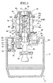
- Fig. 1 is a sectional view of a principal portion of the entire structure of an embodiment of the rotary laser apparatus according to the present invention.
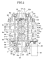
- Fig. 2 is an enlarged view of a principal portion of the light-projecting section.
- Fig. 3 is a decomposed and perspective view of an example of an arranged relation of optical members in a rotation-irradiating section shown in Fig. 2.
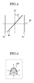
- Fig. 4 is a view showing the positional relation of fan-shaped laser beams shown in Fig. 3.
- Fig. 5 is a view showing the intensity distribution of the laser beams emitted from the laser beam projector shown in Fig. 1.
- Fig. 6 is a decomposed and perspective view showing another example of the arranged relation of the optical members in the rotation-irradiating section shown in Fig.2.
- Fig. 1 shows an outline of a rotary laser apparatus 1 according to the present invention.
- This rotary laser apparatus 1 comprises a casing 2 and a light-projecting unit 3.
- the light-projecting unit 3 comprises a light source section 3A and a rotation-irradiating section 3B.
- a depressed portion 4 having an inversely frusto-conical shape is formed in a central portion of the casing 2.
- the light source portion 3A comprises a laser beam projector 5 and a collimator lens 6 (See Fig. 3).
- the collimator lens 6 converts the laser beam P emitted from the laser beam projector 5 to a parallel light flux P1.
- the light source portion 3A penetrates vertically depressed portion 4, and the light source portion 3A is supported rotatably in the depressed portion via a spherical seat 7.
- the light-projecting section 3A comprises a fixed cylinder 8, which is provided with a rotary cylinder 9 as the rotation-irradiating section 3B.
- the fixed cylinder 8 In the fixed cylinder 8 are opened light-projecting windows 8a to 8c extending in the circumferential direction, which are spaced from each other in a vertical direction.
- the rotary cylinder 9 is provided with light-projecting windows 9a' to 9c' which correspond to the light-projecting windows 8a to 8c, respectively and are spaced from each other in the vertical direction.
- the rotary shaft 9 is supported by the fixed cylinder 8 via bearing members 10 at vertically end portions thereof.
- the rotary cylinder 9 is rotatable around a rotary axis being an optical axis O1 of the collimator lens 6.
- First to third optical members are arranged inside the rotary cylinder 9 at three stages. The outline of the structure of the rotary cylinder 9, which is driven by a scanning motor, will be explained below.
- the fixed cylinder 8 comprises a lower cylinder 8A and an upper cylinder 8B.
- the upper cylinder 8B is fixed to the lower cylinder 8A by means of screws 8C.
- a fitting bracket 8D is fixed to the upper cylinder 8B.
- the scanning motor 8E is fixed to the fixing blanket 8D, and an output gear 8F is fitted to the scanning motor 8E.
- a follower gear 9A is fixed to a lower portion of the rotary cylinder 9 by screws 9B.
- the follower gear 9A meshes with the output gear 8F.
- a cover member 8G is fixed to upper portions of the fixed cylinder 8 and the rotary cylinder 9 by means of screws 8H.
- the rotary cylinder 9 is stably rotated around its axis by the scanning motor 8E.
- the projector 3 is provided with two sets of inclining mechanisms.
- One of the inclining mechanisms is shown in Fig. 1.
- This one inclining mechanism is denoted by a reference numeral 11.
- the inclining mechanism 11 comprises an inclining motor 12, inclining screw members 13 and an inclining nut 14. Rotation of the inclining motor 12 is transmitted to the inclining screw member 13 via a driving gear 15 and an inclining gear 16, so that the inclining nut 14 is vertically moved following rotation of the inclined nut 14 is vertically rotated by rotation of the inclining screw member 13.
- the inclining nut 14 is connected to the light source unit 3 via an inclining arm 17.
- the light-projecting unit 3 is inclined relative to the perpendicular line C1 by vertically moving the inclining nut 14.
- the other inclining mechanism inclines the light source unit 3 in a direction orthogonal to the inclining direction with the inclining mechanism 11.
- the light-projecting unit 3 is provided with a fixed inclination sensor 18 extending in parallel to the extending direction of the inclining arm 17 and a fixed inclination sensor 19 extending in a direction orthogonal to the fixed inclination sensor 18.
- the inclining mechanism 11 makes control to render the fixed inclination sensor 18 horizontally, whereas the other inclining mechanism makes control to render the fixed inclination sensor 19 horizontally.
- the optical axis 01 (the axis of the rotary cylinder 9) is matched with the perpendicular line C1.
- the inclining mechanism is preferably operated to set the rotary laser apparatus 1 itself as horizontally as possible so as to bring the axis of the rotary cylinder 9 into line with the perpendicular line C1.
- the first optical member 20 to the third optical member 22 are arranged in the rotary cylinder 9.
- the first to third optical members 20 to 22 form first to third fan-shaped laser beams 9a to 9c, respectively, which each expand as the laser beams go away from the axis of the rotary cylinder 9 (A sectional plane of each of the first to third fan-shaped laser beams has an oblong shape as shown in Fig. 3).
- a fan-shaped plane of the first fan-shaped laser beam 9a is orthogonal to a rotary plane (horizontal plane) 9d of the rotary cylinder 9.
- a fan-shaped plane of the second fan-shaped laser beam 9b is oblique to that of the first fan-shaped laser beam 9a.
- a fan-shaped plane of the third fan-shaped laser beam 9c is orthogonal to a rotary plane (horizontal plane) 9d of the rotary cylinder 9, and forms a specified angle between the fan-shaped plane of the first fan-shaped laser beam 9a.
- the first optical member 20 comprises a first penta prism 20e and a first lens 20f.
- the first penta prism 20 comprises an incident plane 20a which is orthogonal to the optical axis O1 of the collimator lens 6 and into which parallel light beams are led, a permeable plane 20b which reflects a part of the parallel light beams entering the incident plane 20a and permeates the remainder therethrough, an emitting plane 20c, and a reflecting plane 20d which biases the parallel light beams reflected from the permeable plane 20b in a direction orthogonal to the optical axis of the collimator lens 6 and reflects them toward the emitting plane 20c.
- the first lens 20f converts the parallel light beams P1 emitted from the emitting plane 20c to a first fan-shaped laser flux 9a.
- the second optical member 21 comprises a second penta prism 21e and a second lens 21f.
- the second penta prism 21e comprises an incident plane 21a which is orthogonal to the optical axis O1 of the collimator lens 6 and into which parallel light beams P1 having permeated the permeable plane 20b of the first penta prism 20e are emitted, a permeable plane 21b which reflects a part of the parallel light beam entering the incident plane 21a and permeates the remainder therethrough, an emitting plane 21c, and a reflecting plane 21d which biases the parallel light beams P1 reflected from the permeable plane 21b in a direction orthogonal to the optical axis of the collimator lens 6 and reflects them toward the emitting plane 21c.
- the second lens 21f converts the parallel light beams P1 emitted from the emitting plane 21c to a second fan-shaped laser flux 9b.
- the third optical member 22 comprises a third penta prism 22e and a third lens 22f.
- the third penta prism 22e comprises an incident plane 22a which is orthogonal to the optical axis 01 of the collimator lens 6 and into which parallel light beams P1 having permeated the permeable plane 21b of the second penta prism 21e are led, a first plane 22b which reflects the parallel light beam P1 entering the incident plane 22a, an emitting plane 22c, and a second reflecting plane 22d which biases the parallel light beams reflected from the first reflecting plane 22b in a direction orthogonal to the optical axis of the collimator lens 6 and reflects them toward the emitting plane 22c.
- the third lens 22f converts the parallel light beams P1 emitted from the emitting plane 22c to a third fan-shaped laser flux 9c.
- An edge prism 23 is provided integrally between the first penta prism 20e and the second penta prism 21e.
- the edge prism 23 buries a gap between the first penta prism 20e and the second penta prism 21e, and forms a beam splitter at the permeable plane 20b.
- an edge prism 24 is provided integrally between the second penta prism 21e and the third penta prism 22e.
- the penta prisms 20, 21 and 22 thus integrated are fixed inside the rotary cylinder 9 by a fixing auxiliary member 25, a fixing plate 26 and screws.
- the first to third lenses 20f, 21f and 22f to form the fan-shaped laser beams 9a, 9b and 9c, respectively convex cylindrical lenses are used as shown in Fig. 3.
- the focal distance of the first lens 20f is made equal to that of the third lens 22f.
- the first fan-shaped laser beam 9a is projected deviated from the third fan-shaped layer beam 9c vertically corresponding to a difference in height between the first penta prism 20e and the third penta prism 22e.
- the deviation in the projecting height between the first fan-shaped laser beam 9a and the third fan-shaped laser beam 9c can be ignored at a place far from the axis of the rotary cylinder 9.
- the first fan-shaped laser beam 9a is symmetrical with the third fan-shaped laser 9c via the second fan-shaped laser beam 9b.
- the focal distance of the second lens 21f is (1/cos ⁇ ) times as that of the first lens 20f and the third lens 22f. If the focal distance of the second lens 21f is (1/cos ⁇ ) times that of the first lens 20f and the third lens 22f, the opening angle of the second fan-shaped laser beam 9b is ⁇ /cos ⁇ .
- the opening angle of the second fan-shaped laser beam 9b in the horizontal direction is ( ⁇ /cos ⁇ ) ⁇ sin ⁇ .
- a specified angle of each of the first fan-shaped laser beam 9a and the third fan-shaped laser beam 9b must be not less than ( ⁇ /cos ⁇ ) ⁇ sin ⁇ , and the first and third fan-shaped laser beams 9a and 9c must be spaced by not less than ⁇ ( ⁇ /cos ⁇ ) ⁇ sin ⁇ /2 around the axis of the rotary cylinder 9 with respect to the second fan-shaped laser beam in reverse directions, respectively.
- the open angel of the second fan-shaped laser beam 9b in the height direction is set at (1/ cos ⁇ ) times as great as the opening angle of each of the first and third fan-shaped laser beams 9a and 9c
- the amount of the parallel light flux P1 emitted from the emitting plane 20b is (1/ cos ⁇ ) as great as that of the parallel flux P1 emitted from the emitting plane 20c or that of the parallel light flux P1 emitted from the emitting plane 22c.
- the radiant intensity distribution of the laser beams consisting of the first to third fan-shaped laser beams 9a to 9c, the laser beams emitted from the laser beam projector 5 is adjusted such that the light amount intensity distribution GD may so appear from the peripheral portion to the central portion as to increase the intensity in the light amount distribution at positions near the horizontal direction as shown in Fig. 5.
- first penta prism 20 to the third penta prism 22a, the first edge prism 23, the second edge prism 24 and the fixing auxiliary member 25 to the respectively adjacent members by using an adhesive.
- the first penta prism 20e and the third penta prism 22e are axially fixed in the rotary cylinder 9 under pressure, holding the second penta prism 20e therebetween, while the emitting planes 20c and 22c of the first and third penta prisms 20e and 22e are deviated from each other in a rotating direction of the rotary cylinder 9, such that the first and third fan-shaped planes of the first and third fan-shaped laser beams 9a and 9c, respectively may form the specific angle and that the first and third fan-shaped planes of the first and third fan-shaped laser beams 9a and 9c, respectively may be symmetrical with each other via the fan-shaped plane of the second fan-shaped laser beam 9b.
- the penta prisms 20e to 22e, the edge prisms 23 and 24 and thee fixed auxiliary member 25 are arranged in vertically three stages and fixed to the rotary cylinder 9 by the fixing plate 26 and the screw members 27.
- the optical members 20 to 22 are fixed to the rotary cylinder 9 under pressure, the rotary cylinder 9 is rotatably supported by the fixed cylinder 8, and the optical members 20 to 22 are rotated.
- each of the optical members can be stably rotated without being wobbling.
- the parallel light fluxes P1 is biased in the directions orthogonal to the optical axis O1 by using the penta prisms 20e to 22e. This construction prevents the biased angle from varying before and after the inclination of the penta prism 20 to 22a.
- the specific embodiment of the present invention has been explained. If the laser beam emitted from the laser beam projector 5 is plane-polarized and polarized characteristic exists in the first edge prism 23 and the second edge prism 24, the emitted light amount of the parallel light fluxes P1 emitted from the emitting planes 20c to 22c, in turn the emitted light amount of each of the fan-shaped laser beams 9a to 9c emitted from the respective one of the optical members 20 to 22 varies in the rotating direction, depending upon the rotation angle of the rotary cylinder 9.
- a 1/4 wavelength plate 25 is provided between the collimator lens 6 and the fist penta prism 20e as shown in Fig. 6 such that the crystalline direction of the 1/4 wavelength plate may be 45 degrees relative to the plane-polarized direction of the laser beam.
- the parallel light flux having passed the 1/4 wavelength plate 25 may be circularly polarized.
- a polarization-removing plate may be provided instead of the 1/4 wavelength plate 25, a polarization-removing plate may be provided.
- the laser beam emitted from the collimator lens 6 has an elliptical shape-characteristics. If no processing is effected, the orientating characteristics differ relative to the expanding direction of each of the fan-shaped laser beams 9a to 9c differ depending upon the rotating direction of the rotary cylinder 9. Thus, in this case, the elliptical rate may be removed by a known beam shape-rectifying method such as an anamophoric prism pair.
- the penta prisms are used.
- a penta mirror having an incident mirror plane, a permeable mirror plane, a reflective mirror plane and an emitting mirror plane may be used.
Landscapes
- Physics & Mathematics (AREA)
- Engineering & Computer Science (AREA)
- General Physics & Mathematics (AREA)
- Radar, Positioning & Navigation (AREA)
- Remote Sensing (AREA)
- Laser Beam Processing (AREA)
- Mechanical Optical Scanning Systems (AREA)
- Projection Apparatus (AREA)
- Length Measuring Devices By Optical Means (AREA)
- Optical Elements Other Than Lenses (AREA)
Applications Claiming Priority (1)
| Application Number | Priority Date | Filing Date | Title |
|---|---|---|---|
| JP2004257242A JP3949681B2 (ja) | 2004-09-03 | 2004-09-03 | 回転レーザ装置 |
Publications (3)
| Publication Number | Publication Date |
|---|---|
| EP1632747A2 true EP1632747A2 (de) | 2006-03-08 |
| EP1632747A3 EP1632747A3 (de) | 2011-04-06 |
| EP1632747B1 EP1632747B1 (de) | 2016-10-26 |
Family
ID=35510917
Family Applications (1)
| Application Number | Title | Priority Date | Filing Date |
|---|---|---|---|
| EP05090241.0A Expired - Lifetime EP1632747B1 (de) | 2004-09-03 | 2005-08-19 | Rotierendes Lasergerät |
Country Status (4)
| Country | Link |
|---|---|
| US (1) | US7319515B2 (de) |
| EP (1) | EP1632747B1 (de) |
| JP (1) | JP3949681B2 (de) |
| CN (1) | CN100523729C (de) |
Cited By (2)
| Publication number | Priority date | Publication date | Assignee | Title |
|---|---|---|---|---|
| WO2012000714A1 (de) * | 2010-07-02 | 2012-01-05 | Robert Bosch Gmbh | Vorrichtung zum erzeugen einer lasermarkierung |
| US8526014B2 (en) | 2008-06-19 | 2013-09-03 | Trimble Navigation Limited | Positioning device and method for detecting a laser beam |
Families Citing this family (17)
| Publication number | Priority date | Publication date | Assignee | Title |
|---|---|---|---|---|
| US8238008B2 (en) | 2008-06-09 | 2012-08-07 | Trimble Navigation Limited | Laser transmitter and method |
| JP5550855B2 (ja) | 2009-06-12 | 2014-07-16 | 株式会社トプコン | 回転レーザ出射装置 |
| JP5693827B2 (ja) | 2009-06-17 | 2015-04-01 | 株式会社トプコン | 測量システム |
| CN102830224B (zh) * | 2012-08-28 | 2014-09-24 | 天津市先石光学技术有限公司 | 用于均相发光免疫检测的光路切换机构 |
| US8788154B2 (en) * | 2012-09-12 | 2014-07-22 | Kabushiki Kaisha Topcon | Construction machine control method and construction machine control system |
| US20140111813A1 (en) * | 2012-10-19 | 2014-04-24 | Hamar Laser Instruments, Inc. | Optical assembly and laser alignment apparatus |
| US20140111866A1 (en) * | 2012-10-19 | 2014-04-24 | Hamar Laser Instruments, Inc. | Optical assembly and laser alignment apparatus |
| CN102998885B (zh) * | 2012-11-20 | 2015-09-02 | 芜湖市安曼特微显示科技有限公司 | 对投影仪投影图像失真校正的方法 |
| CN104776796B (zh) * | 2014-01-13 | 2018-11-23 | 西安中科光电精密工程有限公司 | 一种用于室内空间坐标测量的光学发射器及其控制方法 |
| CN106813652A (zh) * | 2015-11-30 | 2017-06-09 | 南京德朔实业有限公司 | 激光发射装置及其光学组件 |
| CN105261271B8 (zh) * | 2015-12-01 | 2018-08-07 | 长春理工大学 | 一种光电综合实验平台 |
| CN105552678B (zh) * | 2016-02-25 | 2018-08-10 | 广东金力变速科技股份有限公司 | 一种激光头供电装置 |
| JP6407936B2 (ja) * | 2016-10-19 | 2018-10-17 | ファナック株式会社 | ビーム分岐装置 |
| DE102016014384B4 (de) * | 2016-12-02 | 2019-01-17 | Carl Zeiss Industrielle Messtechnik Gmbh | Verfahren und Vorrichtung zur Bestimmung der 3D-Koordinaten eines Objekts |
| CN111256599A (zh) * | 2020-03-11 | 2020-06-09 | 江苏理工学院 | 一种散热风扇检测装置 |
| CN112179348B (zh) * | 2020-09-22 | 2022-08-09 | 西安交通大学 | 一种用于光电传感定位网络的轻量化激光扫描机构 |
| CN115236868B (zh) * | 2022-09-22 | 2022-11-29 | 长春理工大学 | 一种高分辨光轴调整装置及高分辨光轴调整方法 |
Family Cites Families (6)
| Publication number | Priority date | Publication date | Assignee | Title |
|---|---|---|---|---|
| US3966328A (en) * | 1973-10-16 | 1976-06-29 | Aga Aktiebolag | Device for generating a spatial reference plane |
| JPH08145675A (ja) | 1994-11-17 | 1996-06-07 | Asahi Optical Co Ltd | レーザ測量装置 |
| US5838431A (en) * | 1996-01-16 | 1998-11-17 | Asahi Kogaku Kogyo Kabushiki Kaisha | Laser marking device |
| US6452668B1 (en) | 1998-10-13 | 2002-09-17 | Arc Second, Inc. | Rotating head optical transmitter for position measurement system |
| JP3816807B2 (ja) | 2002-01-21 | 2006-08-30 | 株式会社トプコン | 位置測定装置及びそれに使用する回転レーザ装置 |
| JP4354343B2 (ja) * | 2004-06-15 | 2009-10-28 | 株式会社トプコン | 位置測定システム |
-
2004
- 2004-09-03 JP JP2004257242A patent/JP3949681B2/ja not_active Expired - Fee Related
-
2005
- 2005-08-19 EP EP05090241.0A patent/EP1632747B1/de not_active Expired - Lifetime
- 2005-08-25 US US11/213,776 patent/US7319515B2/en not_active Expired - Lifetime
- 2005-09-02 CN CNB2005100991486A patent/CN100523729C/zh not_active Expired - Fee Related
Non-Patent Citations (1)
| Title |
|---|
| None |
Cited By (3)
| Publication number | Priority date | Publication date | Assignee | Title |
|---|---|---|---|---|
| US8526014B2 (en) | 2008-06-19 | 2013-09-03 | Trimble Navigation Limited | Positioning device and method for detecting a laser beam |
| US8743376B2 (en) | 2008-06-19 | 2014-06-03 | Trimble Navigation Limited | Surveying instrument and method for detecting a laser beam |
| WO2012000714A1 (de) * | 2010-07-02 | 2012-01-05 | Robert Bosch Gmbh | Vorrichtung zum erzeugen einer lasermarkierung |
Also Published As
| Publication number | Publication date |
|---|---|
| JP3949681B2 (ja) | 2007-07-25 |
| EP1632747A3 (de) | 2011-04-06 |
| EP1632747B1 (de) | 2016-10-26 |
| CN100523729C (zh) | 2009-08-05 |
| CN1743807A (zh) | 2006-03-08 |
| US7319515B2 (en) | 2008-01-15 |
| JP2006071545A (ja) | 2006-03-16 |
| US20060050345A1 (en) | 2006-03-09 |
Similar Documents
| Publication | Publication Date | Title |
|---|---|---|
| EP1632747B1 (de) | Rotierendes Lasergerät | |
| KR101257586B1 (ko) | 광축 조정 장치, 광축 조정 방법 및 투사형 표시 장치 | |
| CN1330929C (zh) | 位置确定装置 | |
| JP4301863B2 (ja) | 測距装置 | |
| JP2000180168A (ja) | 測量機の受光装置 | |
| JP2009236601A (ja) | 測量装置及び測量システム | |
| GB2444138A (en) | Scanning apparatus | |
| JPH0712569A (ja) | 対象反射物体及び対象反射物体検出装置 | |
| CN1155069A (zh) | 距离测定装置 | |
| CN1246665C (zh) | 测量机的光轴自动调节 | |
| US5033845A (en) | Multi-direction distance measuring method and apparatus | |
| US5867263A (en) | Laser survey instrument having a reflection light blocking means | |
| US8045182B2 (en) | Location detection apparatus | |
| JPH11230747A (ja) | レーザ照射装置 | |
| JP2939413B2 (ja) | 対象反射物体検出装置 | |
| JP3413851B2 (ja) | 光走査画像情報検出装置 | |
| JP2580824Y2 (ja) | 焦点調整装置 | |
| JP2021121817A (ja) | 光学式測定装置 | |
| JPH11166969A (ja) | レーザ式測距装置 | |
| JPH10232363A (ja) | 光走査装置 | |
| JP2004125774A (ja) | 光学位置測定装置 | |
| JP4267971B2 (ja) | レーザ光線照準装置及び光軸補償方法 | |
| JP3741478B2 (ja) | ガイド光方向設定装置 | |
| JP2006266891A (ja) | レーザ照射装置 | |
| JPH0571959A (ja) | 光学式微小変位測定装置 |
Legal Events
| Date | Code | Title | Description |
|---|---|---|---|
| PUAI | Public reference made under article 153(3) epc to a published international application that has entered the european phase |
Free format text: ORIGINAL CODE: 0009012 |
|
| AK | Designated contracting states |
Kind code of ref document: A2 Designated state(s): AT BE BG CH CY CZ DE DK EE ES FI FR GB GR HU IE IS IT LI LT LU LV MC NL PL PT RO SE SI SK TR |
|
| AX | Request for extension of the european patent |
Extension state: AL BA HR MK YU |
|
| PUAL | Search report despatched |
Free format text: ORIGINAL CODE: 0009013 |
|
| AK | Designated contracting states |
Kind code of ref document: A3 Designated state(s): AT BE BG CH CY CZ DE DK EE ES FI FR GB GR HU IE IS IT LI LT LU LV MC NL PL PT RO SE SI SK TR |
|
| AX | Request for extension of the european patent |
Extension state: AL BA HR MK YU |
|
| 17P | Request for examination filed |
Effective date: 20111006 |
|
| AKX | Designation fees paid |
Designated state(s): CH DE LI |
|
| 17Q | First examination report despatched |
Effective date: 20120727 |
|
| GRAP | Despatch of communication of intention to grant a patent |
Free format text: ORIGINAL CODE: EPIDOSNIGR1 |
|
| INTG | Intention to grant announced |
Effective date: 20160511 |
|
| GRAS | Grant fee paid |
Free format text: ORIGINAL CODE: EPIDOSNIGR3 |
|
| GRAA | (expected) grant |
Free format text: ORIGINAL CODE: 0009210 |
|
| AK | Designated contracting states |
Kind code of ref document: B1 Designated state(s): CH DE LI |
|
| RIN1 | Information on inventor provided before grant (corrected) |
Inventor name: OHTOMO, FUMIO Inventor name: HAYASHI, KUNIHIRO |
|
| REG | Reference to a national code |
Ref country code: CH Ref legal event code: EP |
|
| REG | Reference to a national code |
Ref country code: DE Ref legal event code: R096 Ref document number: 602005050509 Country of ref document: DE |
|
| REG | Reference to a national code |
Ref country code: CH Ref legal event code: NV Representative=s name: BRAUNPAT BRAUN EDER AG, CH |
|
| REG | Reference to a national code |
Ref country code: DE Ref legal event code: R097 Ref document number: 602005050509 Country of ref document: DE |
|
| PLBE | No opposition filed within time limit |
Free format text: ORIGINAL CODE: 0009261 |
|
| STAA | Information on the status of an ep patent application or granted ep patent |
Free format text: STATUS: NO OPPOSITION FILED WITHIN TIME LIMIT |
|
| 26N | No opposition filed |
Effective date: 20170727 |
|
| REG | Reference to a national code |
Ref country code: CH Ref legal event code: PCAR Free format text: NEW ADDRESS: HOLEESTRASSE 87, 4054 BASEL (CH) |
|
| PGFP | Annual fee paid to national office [announced via postgrant information from national office to epo] |
Ref country code: DE Payment date: 20240702 Year of fee payment: 20 |
|
| PGFP | Annual fee paid to national office [announced via postgrant information from national office to epo] |
Ref country code: CH Payment date: 20240901 Year of fee payment: 20 |
|
| REG | Reference to a national code |
Ref country code: DE Ref legal event code: R071 Ref document number: 602005050509 Country of ref document: DE |
|
| REG | Reference to a national code |
Ref country code: CH Ref legal event code: PL |