EP1632701B1 - Flat valve device - Google Patents
Flat valve device Download PDFInfo
- Publication number
- EP1632701B1 EP1632701B1 EP20040745804 EP04745804A EP1632701B1 EP 1632701 B1 EP1632701 B1 EP 1632701B1 EP 20040745804 EP20040745804 EP 20040745804 EP 04745804 A EP04745804 A EP 04745804A EP 1632701 B1 EP1632701 B1 EP 1632701B1
- Authority
- EP
- European Patent Office
- Prior art keywords
- cover
- hole
- facing
- gas
- outward
- Prior art date
- Legal status (The legal status is an assumption and is not a legal conclusion. Google has not performed a legal analysis and makes no representation as to the accuracy of the status listed.)
- Expired - Lifetime
Links
- 238000002347 injection Methods 0.000 claims abstract description 35
- 239000007924 injection Substances 0.000 claims abstract description 35
- 230000002093 peripheral effect Effects 0.000 claims abstract description 22
- 238000007789 sealing Methods 0.000 claims abstract description 21
- 238000012856 packing Methods 0.000 description 12
- 238000010586 diagram Methods 0.000 description 10
- 239000000463 material Substances 0.000 description 5
- 239000004033 plastic Substances 0.000 description 4
- 229920003023 plastic Polymers 0.000 description 4
- 229910052782 aluminium Inorganic materials 0.000 description 2
- XAGFODPZIPBFFR-UHFFFAOYSA-N aluminium Chemical compound [Al] XAGFODPZIPBFFR-UHFFFAOYSA-N 0.000 description 2
- XLYOFNOQVPJJNP-UHFFFAOYSA-N water Substances O XLYOFNOQVPJJNP-UHFFFAOYSA-N 0.000 description 2
- 239000000853 adhesive Substances 0.000 description 1
- 230000001070 adhesive effect Effects 0.000 description 1
- 230000015572 biosynthetic process Effects 0.000 description 1
- 230000000694 effects Effects 0.000 description 1
- 239000013013 elastic material Substances 0.000 description 1
- 230000002708 enhancing effect Effects 0.000 description 1
- 239000007769 metal material Substances 0.000 description 1
- 238000000034 method Methods 0.000 description 1
- 230000035699 permeability Effects 0.000 description 1
- 230000002265 prevention Effects 0.000 description 1
Images


Classifications
-
- F—MECHANICAL ENGINEERING; LIGHTING; HEATING; WEAPONS; BLASTING
- F16—ENGINEERING ELEMENTS AND UNITS; GENERAL MEASURES FOR PRODUCING AND MAINTAINING EFFECTIVE FUNCTIONING OF MACHINES OR INSTALLATIONS; THERMAL INSULATION IN GENERAL
- F16K—VALVES; TAPS; COCKS; ACTUATING-FLOATS; DEVICES FOR VENTING OR AERATING
- F16K15/00—Check valves
- F16K15/20—Check valves specially designed for inflatable bodies, e.g. tyres
-
- Y—GENERAL TAGGING OF NEW TECHNOLOGICAL DEVELOPMENTS; GENERAL TAGGING OF CROSS-SECTIONAL TECHNOLOGIES SPANNING OVER SEVERAL SECTIONS OF THE IPC; TECHNICAL SUBJECTS COVERED BY FORMER USPC CROSS-REFERENCE ART COLLECTIONS [XRACs] AND DIGESTS
- Y10—TECHNICAL SUBJECTS COVERED BY FORMER USPC
- Y10T—TECHNICAL SUBJECTS COVERED BY FORMER US CLASSIFICATION
- Y10T137/00—Fluid handling
- Y10T137/3584—Inflatable article [e.g., tire filling chuck and/or stem]
- Y10T137/3786—Removable valve head and seat unit [valve insides]
Definitions
- the present invention relates to a flat valve device mounted on gas-containing structures such as water playthings, automobile tires and attraction air houses for gas injection and evacuation.
- Gas-containing structures such as water playthings and car tires conventionally employ a valve for injecting and evacuating a gas, particularly a one-way valve, which allows the flow of a gas in only one direction, but no flow in the opposite direction.
- a valve for injecting and evacuating a gas particularly a one-way valve, which allows the flow of a gas in only one direction, but no flow in the opposite direction.
- the air is blown into such a structure or a gas is inflated by means of a gas-filled inflator such as an air pump.
- the gas-containing structure releases the gas by opening a valve.
- Japanese Unexamined Patent Publication No. 8-61534 discloses an air vent valve for air removal from the tire.
- the screwing of the air vent valve into a tire valve will open the valve, thereby causing the filled air to push up the valve element against an energizing force of a spring and providing an air vent space for air release.
- the completion of air release with its pressure reduction at a predetermined level will be followed by spring restoration, whose force exceeds the released gas pressure to pull back the valve element to fill the air vent space.
- FIG. 10-213243 discloses an air valve device with a flat surface to be mounted on a tire for air inflation.
- a valve body is placed under the wheel surface with a flat cover being screwed therein, to improve the tire valve appearance and prevent the valve from causing failure by coming in contact with such objects as curbs.
- the flat cover is removed and a coupler including an extensible presser pin is screwed to the valve body. With being connected to an air nozzle of an air compressor, the coupler pushes the extensible presser pin against a valve opening pin to fill the air.
- JP 11 325 284 discloses a flat valve device according to the preamble of claim 1.
- the valve body seems to have no outward-facing protrusion, showing a flat shape, but the valve body is merely placed unobserved inside the tire.
- the built-in valve which comprises conventional-type deformation- and deterioration-prone parts such as coil springs and rubber packing, must be frequently replaced.
- the above invention is characterized by an appearance improvement, more simplified or swift air evacuation is not considered.
- one object of the present invention to solve the aforementioned problems by providing a flat valve device of a smaller size which can complete easy and swift air evacuation, in which the airtightness of a gas-containing structure can be maintained and the operational safety can be assured, with requiring no extra parts to be supplied.
- the flat valve device of the present invention is characterized by a circular frame member to be mounted on the opening of a gas-containing structure filled with the gas therein, a round body member to be mounted on the inner peripheral surface of this circular frame member, and a valve provided inside the round body member. More specifically, there is provided a valve accommodating space within said round body member to accommodate said valve, from which an outward-facing through hole and an inward-facing through hole are given so as to pass through said gas-containing structure outwardly and inwardly, respectively.
- the said valve includes a sealing cover to be inserted into said outward-facing through hole for maintaining an airproof state, and an energizing member which normally energizes the sealing cover toward said outward-facing through hole.
- the said round body member has a circular recess facing the surface with the outward-facing through hole, and a rotating cover to be pressed onto the bottom surface of said circular recess by rotation.
- the said outward-facing through hole is prepared off the center of said circular recess, and said rotating cover includes a gas injection hole for gas injection so as to have the degree of eccentricity identical to that of said outward-facing through hole.
- the circular recess in this invention is of a higher height than that of the rotating cover, and on the inner peripheral surface of the circular recess, a part for preventing cover removal may project out over said rotating cover to prevent the removal of said rotating cover.
- the gas injection hole is preferably positioned so as to connect through the outward-facing through hole.
- the part for preventing cover removal there is provided the part for preventing cover removal, the under surface of which may have a cover pressing part, and a pressure receiving part is provided on the upper surface of the rotating cover opposite the cover pressing part, whereby said cover pressing part will press said pressure receiving part downwardly when said rotating cover is rotated.
- the gas injection hole be positioned so as not to connect through the outward-facing through hole at the time the rotating cover abuts on the bottom surface of the circular recess to prevent sudden gas leakage from the valve.
- this invention provides a flat valve device of a smaller size which readily completes gas evacuation in a short period of time, in which a high airtightness of a gas-containing structure can be maintained and the operational safety can be assured, with requiring no extra parts to be supplied.
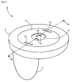
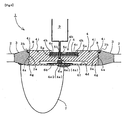
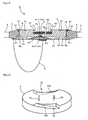
- FIG. 1 shows an overall perspective view of the first embodiment of a flat valve device 1
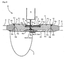
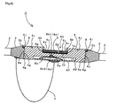
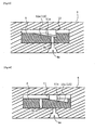
- Figure 2 demonstrates a sectional view taken on line 2-2 of Fig. 1
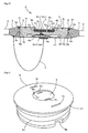
- the flat valve device 1 of the first embodiment which is several centimeters in diameter and may be shaped in approximately one centimeter, comprises a nearly ring-shaped circular frame member 3 to be mounted on the opening of a gas-containing structure 2 for gas injection and evacuation, a thin round body member 4 to be removably mounted on the inner peripheral surface of the circular frame member 3, a rotating cover 5 to be rotatably mounted on the round body member 4, and a valve 6 provided inside the round body member 4 for adjusting the gas flow.
- the circular frame member 3 is fabricated in the form of a ring with an opening of a perfect circle therein. Its outer peripheral surface is secured to the opening of the gas-containing structure 2 for filling or evacuating a gas by means of a thermocompression method or adhesives. Also, there is provided a female thread part for cover rotation 3a on the inner peripheral surface of the circular frame member 3 to removably hold the round body member 4. On the edge of the inner peripheral surface to the outward side, a flange accommodating part 3b is given to accommodate a flange part 4i of the round body member 4 to be described later.
- the circular frame member 3 is fabricated from a rigid plastic material, but other less deteriorated materials such as aluminum may be employed. Though the circular frame member 3 has a circular form to eliminate stress concentration on a limited pressure bonding part for air inflation, the member may be polygonally shaped to reduce stress concentration to a certain level.
- the round body member 4 is fabricated in a thin round shape from less deteriorated and high-strength rigid plastic materials as well as the circular frame member 3.
- the outer peripheral surface of the round body member 4 has a male thread part for cover rotation 4a for engagement with a female screw part 3a of the circular frame member 3.
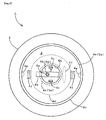
- the surface of the round body member 4 to the outward side is provided with a concentric circular recess 4b having a nearly same diameter as that of the rotating cover 5.
- the circular recess 4b has a female thread part for cover rotation 4c on the inner peripheral surface thereof to rotatably hold the rotating cover 5.
- the round body member 4 includes a valve accommodating space 4d, being made therein in a flat and nearly circular form and given below the aforementioned circular recess 4b.
- the valve accommodating space 4d is provided with an outward-facing through hole 4e and an inward-facing through hole 4f, which pass through the gas-containing structure 2 outwardly and inwardly, respectively.
- the outward-facing through hole 4e which runs through the bottom surface of the circular recess 4b, is prepared off the center of the circular recess 4b, not in the center.
- the outward-facing through hole 4e includes a straight part 4e1 in its nearly half height to the outward side with a constant internal diameter, and a tapered part 4e2 in its another nearly half height to the inward side, with an internal diameter reduced at a determined inclination toward the outward side.
- a sealing cover 6a of the valve 6 to be later mentioned will be inserted and sealed into the tapered part 4e2.
- the valve 6, which is placed within the valve accommodating space 4d, comprises a sealing cover 6a and an energizing member 6b.
- the sealing cover 6a is fabricated with a truncated cone shape with the same inclination as that of the tapered part 4e2 of the outward-facing through hole 4e. Such a formation may facilitate the positioning of the sealing cover 6a in the outward-facing through hole 4e and assure cover sealing.
- the sealing cover 6a may be of a rubber material, but other less deteriorated metal materials such as aluminum and rigid plastics may be employed with a high-precision processing.
- the energizing member 6b fabricated from an elastic member with the curved flat form, is secured to the bottom surface of the valve accommodating space 4d in such a manner that its curved convex part projects toward the outward-facing through hole 4e.
- the sealing cover 6a mounted on the surface of said curved convex part so as to be inserted into the tapered part 4e2 of the outward-facing through hole 4e, a high airtightness with the outward-facing through hole 4e can be ensured.
- the outer peripheral surface of the round body member 4 is provided with a certain length of a groove for preliminary gas evacuation 4g leading to the gas-containing structure 2.
- the groove for preliminary gas evacuation 4g provides a vent for preliminary gas evacuation when the round body member 4 is removed from the circular frame member 3 to release all the gas.
- the circular recess 4b of the round body member 4 is designed to have a height, larger than that of the rotating cover 5, to accommodate the entire rotating cover 5.
- a centrally-directed circular part for preventing cover removal 4h is made from the upper edge of the circular recess 4b projecting over the rotating cover 5, whereby the rotating cover 5 may not be removed from the round body member 4.
- a flange part 4i is extended on the upper edge of the outer peripheral surface of the round body member 4 to prevent the round body member 4 from getting into the inward side of the circular frame member 3.
- the first embodiment employs a rubber packing 8 between this flange part 4i and the flange accommodating part 3b.
- the packing 8, as shown in Figures 2 and 9 is inserted into a concave groove provided on the flange accommodating part 3b of the circular frame member 3.
- the flange part 4i of the round body member 4 includes a convex part to correspond to a concave part of the packing 8 to maintain a high airtightness after said round body member 4 is screwed.
- the outwardly-directed surface of the round body member 4 (see the upper surface in Figure 2 ) is provided with a pair of engaging grooves for cover rotation 4j, 4j, which are symmetrical in position.
- the engaging grooves for cover rotation 4j, 4j are made on the round body member 4 in such a manner that the section shows a downward slant toward the center of the round body member 4 to be rotatably engaged by means of a proper rotating jig (not shown).
- the round body member 4 and the circular frame member 3 are connected with each other inside the gas-containing structure 2 by a connecting wire 7.
- the connection of the connecting wire 7 is rotatably mounted with no intertwining, even if the round body member 4 is rotated.
- the rotating cover 5 fabricated in a thin circular form from a rigid plastic material, is inserted into the circular recess 4b.
- a male thread part for cover rotation 5a is provided to screw to the female thread part for cover rotation 4c of the circular recess 4b.
- the rotating cover 5 includes a gas injection hole 5b prepared off the center thereof passing through in the thickness direction.
- the gas injection hole 5b is provided so as to have a degree of eccentricity identical to that of the above mentioned outward-facing through hole 4e.
- the position of the gas injection hole 5b is determined in such a manner that it is not connected through the outward-facing through hole 4e at the time the rotating cover 5 is abutted on the bottom surface of the circular recess 4b. Thereafter, the abutted rotating cover 5 will seal the outward-facing through hole 4e, resulting in a high airtightness.
- the gas injection hole 5b is positioned to connect through the outward-facing through hole 4e when the rotating cover 5 is rotated to abut it on the part for preventing cover removal 4h.
- the part for preventing cover removal 4h also provides a criterion for determining an air inflation position.
- the surface of the rotating cover 5 to the outward side is provided with a pair of engaging grooves for cover rotation 5c, 5c as well as the round body member 4.
- the rotating cover 5 screwed to the round body member 4 is rotated at a predetermined angle.
- the gas injection hole 5b will be rotated until it connects through the outward-facing through hole 4e.
- the rotation of the rotating cover 5 may employ an ungualform rotating jig (not shown) to be engaged with the engaging grooves for cover rotation 5c.
- the gas injection hole 5b may be precisely positioned on the outward-facing through hole 4e.
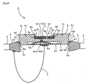
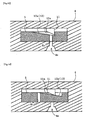
- a gas-filled inflator 9 will be inserted into the holes 5b and 4e to provide high-pressure gas as shown in Figure 5 .
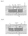
- This high-pressure gas presses the sealing cover 6a to the inward side against the energizing force of the energizing member 6b, thereby creating a gap with a tapered part 4e2 (see Figure 6 ).
- the gas comes in the gap, it passes through the valve accommodating space 4d and the inward-facing through hole 4f to be filled in the gas-containing structure 2.
- a ring-shaped rubber packing 10 may be placed between the bottom surface of the circular recess 4b and the rotating cover 5 to enhance airtightness.
- a rubber piece may be mounted on a female thread part or a male thread part.
- the round body member 4 is removed from the circular frame member 3 for swift gas release.
- the rotating jig (not shown) is engaged with the engaging grooves for cover rotation 4j, 4j of the round body member 4 to be rotated to the outward side for removal. Even if the jig is accidentally rotated to the inward side, the flange part 4i will abut on the flange accommodating part 3b of the circular frame member 3, thereby preventing the falling of the round body member 4 inside the container.
- the completion of the removal of the round body member 4 from the circular frame member 3 releases the gas contained in the gas-containing structure 2 from the opening of the circular frame member 3 for a short period of time.
- the resultant pressure reduction by the groove for preliminary gas evacuation 4g prevents the round body member 4 from springing out due to a high internal pressure. Also, since the connecting wire 7 links the circular frame member 3 to the round body member 4, the round body member 4 will not be lost.
- the above first embodiment provides a flat valve device of a smaller size which assures a high airtightness of the gas-containing structure 2 and the operational safety. Moreover, this device can perform swift gas release, with no extra parts to be supplied.
- the energizing member 6b is secured to the bottom surface of the valve accommodating space 4d in such a manner that its curved convex part projects toward the outward-facing through hole 4e, and the sealing cover 6a is secured to said curved convex part. Therefore, the valve can be made flat with a simplified structure.
- the shape of the outward-facing through hole 4e and the sealing cover 6a is characterized by a taper of the same inclination with hole diameters reduced to the outward side, thereby enhancing a high airtightness using a high internal pressure in the gas-containing structure 2. Even if the sealing cover 6a comes off from the outward-facing through hole 4e when the gas is injected, the sealing cover 6a can readily return to the outward-facing through hole 4e with a high probability.
- the rotating cover 5 whose gas injection hole 5b is designed to connect through the outward-facing through hole 4e at a determined rotation angle, seals the outward-facing through hole 4e at the time the rotating cover 5 is abutted on the bottom surface of the circular recess 4b.
- the rotating cover 5 causes no sudden gas leakage with a high operational safety despite the damage of the valve 6.
- the rotating cover 5 abuts on the part for preventing cover removal 4h even if the rotating cover 5 is excessively rotated, thereby preventing any removal of the rotating cover 5.
- the abutting of the rotating cover 5 on the part for preventing cover removal 4h will link the gas injection hole 5b to the outward-facing through hole 4e, whereby it is not necessary to visually examine the positions of the holes 5b and 4e in each gas injection operation.
- the round body member 4 is excessively tightened to the inward side, the flange part 4i will always abut on the flange accommodating part 3b of the circular frame member 3, thus the round body member 4 will not fall into the gas-containing structure 2.
- the rotation of the flat upper surfaces of the round body member 4 and the rotating cover 5 requires a rotating jig.
- the gas-filled inflator 9 may be provided with such a function.
- the gas-filled inflator 9 may be provided with an engaging part (not shown) with the engaging groove for cover rotation 5c to insert a gas injecting outlet into the gas injection hole 5b. Consequently, since the gas-filled inflator 9 rotates the rotating cover 5 for gas injection and then immediately seals the outward-facing through hole 4e, air leakage can be prevented at the time the gas-filled inflator 9 is removed.
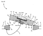
- the flat valve device of the second embodiment is characterized by an alternative means by which said rotating cover 5 is pressed onto said circular recess 4b, instead of the female thread part for cover rotation 4c of the circular recess 4b and the male thread part for cover rotation 5a of the rotating cover 5.
- a cover pressing part 11 on the under surface of a part for preventing cover removal 4h, and a canaliform pressure receiving part 12 is given on the upper surface of a rotating cover 5 opposite the cover pressing part 11.
- a cover pressing part 11 includes an inclined plane for cover pressing 11a, while a pressure receiving part 12 is provided on the upper surface with an inclined plane for receiving pressure 12a whose inclination is almost the same as that of said inclined plane for cover pressing 11a.
- the arc length of the two pressure receiving parts 12, 12 is set as one quarter of the circumference.
- the shapes of the cover pressing part 11 and the pressure receiving part 12 in the second embodiment may be determined in various patterns, if the rotating cover 5 can be pressed on the bottom surface of the circular recess 4b.
- the inclined plane for cover pressing 11a may have a steeper slope than that of the inclined plane for receiving pressure 12a, or may have a flat surface or a curved convex surface.
- the cover pressing part 11 and the pressure receiving part 12 may have alternate shapes. Specifically, the cover pressing part 11 may be given in the canaliform form with about one quarter of the circumference of the part for preventing cover removal 4h, while the pressure receiving part 12 may be formed into a convex shape. Obviously, the cover pressing part 11 may be formed convex with the inclined plane for cover pressing 11 a.
- the under surface of the cover pressing part 11 or the upper surface of the pressure receiving part 12 are not required to have an inclined plane. If the rotating cover 5 can be pressed on the bottom surface of the circular recess 4b, respective surfaces may be provided with curved convex surfaces 11b and 12b, respectively.
- this embodiment discloses the groove for preliminary gas evacuation 4g provided on the outer peripheral surface of the round body member 4, but as shown in Figure 21 , the inner peripheral surface of the circular frame member 3 may include the groove for preliminary gas evacuation 4g from a nearly central position on the central axis to the outward side so as to connect between the inward and outward sides of the gas-containing structure 2.
- this embodiment shows the packing 8 secured to the flange accommodating part 3b, however as shown in Figure 21 , the packing 8 may be mounted on the flange part 4i, and the flange accommodating part 3b may be provided with a concave groove for engagement with the packing 8.
- a convex part may be prepared.
- this embodiment employs only one inward-facing through hole 4f, a plurality of holes may be provided for increasing permeability.
Landscapes
- Engineering & Computer Science (AREA)
- General Engineering & Computer Science (AREA)
- Mechanical Engineering (AREA)
- Filling Or Discharging Of Gas Storage Vessels (AREA)
- Details Of Valves (AREA)
- Feeding And Controlling Fuel (AREA)
- Magnetically Actuated Valves (AREA)
- Self-Closing Valves And Venting Or Aerating Valves (AREA)
- Check Valves (AREA)
- Taps Or Cocks (AREA)
- Valve Housings (AREA)
- Closures For Containers (AREA)
Applications Claiming Priority (2)
| Application Number | Priority Date | Filing Date | Title |
|---|---|---|---|
| JP2003168506A JP3504945B1 (ja) | 2003-06-12 | 2003-06-12 | フラットバルブ装置 |
| PCT/JP2004/008210 WO2004111510A1 (ja) | 2003-06-12 | 2004-06-11 | フラットバルブ装置 |
Publications (3)
| Publication Number | Publication Date |
|---|---|
| EP1632701A1 EP1632701A1 (en) | 2006-03-08 |
| EP1632701A4 EP1632701A4 (en) | 2008-08-27 |
| EP1632701B1 true EP1632701B1 (en) | 2009-11-18 |
Family
ID=32025672
Family Applications (1)
| Application Number | Title | Priority Date | Filing Date |
|---|---|---|---|
| EP20040745804 Expired - Lifetime EP1632701B1 (en) | 2003-06-12 | 2004-06-11 | Flat valve device |
Country Status (9)
| Country | Link |
|---|---|
| US (1) | US7044443B2 (es) |
| EP (1) | EP1632701B1 (es) |
| JP (1) | JP3504945B1 (es) |
| CN (1) | CN100334377C (es) |
| AT (1) | ATE449276T1 (es) |
| DE (1) | DE602004024198D1 (es) |
| ES (1) | ES2333430T3 (es) |
| RU (1) | RU2344327C2 (es) |
| WO (1) | WO2004111510A1 (es) |
Families Citing this family (3)
| Publication number | Priority date | Publication date | Assignee | Title |
|---|---|---|---|---|
| JP4234777B1 (ja) | 2008-05-30 | 2009-03-04 | 浩平 中村 | 接続構造 |
| US8316596B2 (en) * | 2009-09-15 | 2012-11-27 | Pella Corporation | IG unit membrane valve and pressure modification |
| CN113757441B (zh) * | 2021-08-21 | 2024-09-24 | 华东矿用设备有限公司 | 一种液压单向阀 |
Family Cites Families (29)
| Publication number | Priority date | Publication date | Assignee | Title |
|---|---|---|---|---|
| US1993534A (en) * | 1934-05-07 | 1935-03-05 | Edmund G Stoltz | Back water valve for drains |
| US2566576A (en) * | 1947-04-01 | 1951-09-04 | Kestral Corp | Valve construction |
| GB639593A (en) * | 1947-09-20 | 1950-06-28 | Cascelloid Ltd | Improvements in or relating to inflatable articles and valves therefor |
| US2488456A (en) * | 1947-11-17 | 1949-11-15 | Walker Alexander Duncan | Air valve |
| FR2379001A1 (en) * | 1977-01-28 | 1978-08-25 | Angeviniere Sa | Inflation valve for multi-compartment inflatable dinghy - has body housed in threaded bush which is fixed in place by sealing washer and lock nut |
| JPS6044668A (ja) | 1983-08-19 | 1985-03-09 | Shoichi Nakada | 極微量の液体流量の調整方法と装置 |
| CA1277783C (en) * | 1986-01-21 | 1990-12-11 | Robert A. Walker | Air mattress with filler check valve assembly |
| US4762145A (en) * | 1987-05-13 | 1988-08-09 | G.S.D. Sports Equipment S.R.L. | Underwater pressure relief valve |
| NL8800020A (nl) * | 1988-01-06 | 1989-08-01 | Henk Schram | Opblaasbaar lichaam met een ventiel, en een verpakking met een dergelijk lichaam. |
| JPH03117857A (ja) | 1989-09-29 | 1991-05-20 | Aisin Seiki Co Ltd | 往復動機械 |
| JPH0718614Y2 (ja) * | 1989-10-19 | 1995-05-01 | 大日本印刷株式会社 | 流体連結具 |
| JPH03117857U (es) * | 1990-03-16 | 1991-12-05 | ||
| US5203831A (en) * | 1992-10-05 | 1993-04-20 | Survival Engineering, Inc. | Topping and dumping valve for inflatable structures |
| JP2655387B2 (ja) | 1993-06-29 | 1997-09-17 | 住友ゴム工業株式会社 | 舗装用弾性ブロックおよびその製造法 |
| JP2916747B2 (ja) | 1994-08-18 | 1999-07-05 | 旭産業株式会社 | 空気抜き弁 |
| JPH0949515A (ja) | 1995-08-08 | 1997-02-18 | Tsuda Kogyo Kk | 管継手ボルト及び管継手ボルトの製造方法 |
| JPH10167334A (ja) | 1996-12-03 | 1998-06-23 | Kutsumo Kanagata:Kk | 空気抜き開閉弁付き容器 |
| IT1289460B1 (it) * | 1996-12-18 | 1998-10-15 | Scoprega S P A | Struttura di valvola particolarmente per canotti pneumatici |
| JPH10213243A (ja) | 1997-01-30 | 1998-08-11 | Susumu Sadayama | フラットエア−バルブ装置 |
| US5839488A (en) * | 1997-05-29 | 1998-11-24 | Peters; Gerald L. | Hands-off low-air-loss quick-connect quick-disconnect fast-fill dunnage bag filling valve-nozzle assembly & system |
| JP3374190B2 (ja) * | 1998-05-11 | 2003-02-04 | 積水化成品工業株式会社 | 逆止弁および断熱コンテナ |
| JP2001153103A (ja) | 1999-11-29 | 2001-06-08 | Hitachi Constr Mach Co Ltd | リリーフ弁 |
| JP2001173818A (ja) * | 1999-12-21 | 2001-06-29 | Furuya Kogyo Kk | 逆止弁、圧縮収納用包装袋及び緩衝用具 |
| JP3073899U (ja) | 2000-06-07 | 2000-12-15 | 三ツ星ベルト株式会社 | 流量調節部付き給液装置 |
| JP2002022042A (ja) | 2000-07-05 | 2002-01-23 | Seiko Epson Corp | 逆止弁及び逆止弁継ぎ手 |
| US6553728B1 (en) * | 2000-11-20 | 2003-04-29 | Cardinal Ig Company | Insulating glass unit pressure equalization valve |
| JP3598315B2 (ja) | 2000-12-05 | 2004-12-08 | 小川 宏二 | メスネジ山とオスネジ山との接続機構 |
| US6648004B2 (en) * | 2001-02-15 | 2003-11-18 | Pleasure Time Products (Hong Kong) Limited | Air valve for inflatable article |
| US7025080B2 (en) * | 2001-11-13 | 2006-04-11 | Wass Lloyd G | Cross over valve |
-
2003
- 2003-06-12 JP JP2003168506A patent/JP3504945B1/ja not_active Expired - Fee Related
-
2004
- 2004-06-11 WO PCT/JP2004/008210 patent/WO2004111510A1/ja not_active Ceased
- 2004-06-11 ES ES04745804T patent/ES2333430T3/es not_active Expired - Lifetime
- 2004-06-11 EP EP20040745804 patent/EP1632701B1/en not_active Expired - Lifetime
- 2004-06-11 CN CNB2004800159012A patent/CN100334377C/zh not_active Expired - Fee Related
- 2004-06-11 RU RU2006101057A patent/RU2344327C2/ru not_active IP Right Cessation
- 2004-06-11 DE DE200460024198 patent/DE602004024198D1/de not_active Expired - Lifetime
- 2004-06-11 US US10/518,684 patent/US7044443B2/en not_active Expired - Lifetime
- 2004-06-11 AT AT04745804T patent/ATE449276T1/de not_active IP Right Cessation
Also Published As
| Publication number | Publication date |
|---|---|
| JP2006242198A (ja) | 2006-09-14 |
| ATE449276T1 (de) | 2009-12-15 |
| HK1092203A1 (zh) | 2007-02-02 |
| CN100334377C (zh) | 2007-08-29 |
| CN1802529A (zh) | 2006-07-12 |
| ES2333430T3 (es) | 2010-02-22 |
| RU2006101057A (ru) | 2006-06-27 |
| DE602004024198D1 (de) | 2009-12-31 |
| JP3504945B1 (ja) | 2004-03-08 |
| US20050247903A1 (en) | 2005-11-10 |
| RU2344327C2 (ru) | 2009-01-20 |
| WO2004111510A1 (ja) | 2004-12-23 |
| US7044443B2 (en) | 2006-05-16 |
| EP1632701A4 (en) | 2008-08-27 |
| EP1632701A1 (en) | 2006-03-08 |
Similar Documents
| Publication | Publication Date | Title |
|---|---|---|
| KR102090634B1 (ko) | 가스 실린더 밀봉을 위한 방법 및 기기 | |
| EP2123432B1 (en) | Sealing device | |
| CN102066206B (zh) | 容器防脱构造及密封打气装置 | |
| US8820587B2 (en) | Connector | |
| JP6817368B2 (ja) | シール剤ディスペンサ | |
| NZ527143A (en) | Air bag inflation/deflation system | |
| US4995417A (en) | One-piece tire valve adaptor | |
| CN110494385A (zh) | 具有附接的通气系统的桶封闭件 | |
| US5871031A (en) | Removable three position valve | |
| US3677429A (en) | Nipple assembly and package | |
| EP1632701B1 (en) | Flat valve device | |
| US7419066B1 (en) | Vented cap for fluid conduit | |
| US6019150A (en) | Tire with tube containing sealant | |
| JP3229328U (ja) | 車載用空気圧縮機の直列接続フレキシブル管 | |
| JP2009056681A (ja) | タイヤのパンク修理装置 | |
| JP4340477B2 (ja) | 安全タイヤ用バルブ、カプラー付き充填アダプター、放圧アダプター、及び放圧方法 | |
| US7789563B2 (en) | Valve gear | |
| JP7275796B2 (ja) | パンク修理キット | |
| JPH1081378A (ja) | 圧縮ガス噴出用液体のための容器 | |
| WO2007016204A2 (en) | Inflator manifold | |
| HK1092203B (en) | Flat valve device | |
| EP1368244A1 (fr) | Dispositif de bouchage, col compatible avec ce dispositif et recipient comprenant un tel col bouche par un tel dispositif | |
| JP2003300569A (ja) | 多重構造エアゾール容器用パッキン、多重構造エアゾール容器及び多重構造エアゾール容器の製造方法 | |
| EP0898101A1 (fr) | Valve de sécurité en caoutchouc pour jante de roue comportant un pneu sans chambre à air | |
| JP3021231U (ja) | ラムネ壜のキャップ構造 |
Legal Events
| Date | Code | Title | Description |
|---|---|---|---|
| PUAI | Public reference made under article 153(3) epc to a published international application that has entered the european phase |
Free format text: ORIGINAL CODE: 0009012 |
|
| 17P | Request for examination filed |
Effective date: 20051222 |
|
| AK | Designated contracting states |
Kind code of ref document: A1 Designated state(s): AT BE BG CH CY CZ DE DK EE ES FI FR GB GR HU IE IT LI LU MC NL PL PT RO SE SI SK TR |
|
| DAX | Request for extension of the european patent (deleted) | ||
| A4 | Supplementary search report drawn up and despatched |
Effective date: 20080730 |
|
| GRAP | Despatch of communication of intention to grant a patent |
Free format text: ORIGINAL CODE: EPIDOSNIGR1 |
|
| GRAS | Grant fee paid |
Free format text: ORIGINAL CODE: EPIDOSNIGR3 |
|
| GRAA | (expected) grant |
Free format text: ORIGINAL CODE: 0009210 |
|
| AK | Designated contracting states |
Kind code of ref document: B1 Designated state(s): AT BE BG CH CY CZ DE DK EE ES FI FR GB GR HU IE IT LI LU MC NL PL PT RO SE SI SK TR |
|
| REG | Reference to a national code |
Ref country code: GB Ref legal event code: FG4D |
|
| REG | Reference to a national code |
Ref country code: CH Ref legal event code: EP |
|
| REG | Reference to a national code |
Ref country code: IE Ref legal event code: FG4D |
|
| REF | Corresponds to: |
Ref document number: 602004024198 Country of ref document: DE Date of ref document: 20091231 Kind code of ref document: P |
|
| REG | Reference to a national code |
Ref country code: SE Ref legal event code: TRGR |
|
| REG | Reference to a national code |
Ref country code: GR Ref legal event code: EP Ref document number: 20090403278 Country of ref document: GR |
|
| REG | Reference to a national code |
Ref country code: ES Ref legal event code: FG2A Ref document number: 2333430 Country of ref document: ES Kind code of ref document: T3 |
|
| REG | Reference to a national code |
Ref country code: NL Ref legal event code: VDEP Effective date: 20091118 |
|
| PG25 | Lapsed in a contracting state [announced via postgrant information from national office to epo] |
Ref country code: FI Free format text: LAPSE BECAUSE OF FAILURE TO SUBMIT A TRANSLATION OF THE DESCRIPTION OR TO PAY THE FEE WITHIN THE PRESCRIBED TIME-LIMIT Effective date: 20091118 Ref country code: PT Free format text: LAPSE BECAUSE OF FAILURE TO SUBMIT A TRANSLATION OF THE DESCRIPTION OR TO PAY THE FEE WITHIN THE PRESCRIBED TIME-LIMIT Effective date: 20100318 |
|
| PG25 | Lapsed in a contracting state [announced via postgrant information from national office to epo] |
Ref country code: SI Free format text: LAPSE BECAUSE OF FAILURE TO SUBMIT A TRANSLATION OF THE DESCRIPTION OR TO PAY THE FEE WITHIN THE PRESCRIBED TIME-LIMIT Effective date: 20091118 Ref country code: PL Free format text: LAPSE BECAUSE OF FAILURE TO SUBMIT A TRANSLATION OF THE DESCRIPTION OR TO PAY THE FEE WITHIN THE PRESCRIBED TIME-LIMIT Effective date: 20091118 Ref country code: CY Free format text: LAPSE BECAUSE OF FAILURE TO SUBMIT A TRANSLATION OF THE DESCRIPTION OR TO PAY THE FEE WITHIN THE PRESCRIBED TIME-LIMIT Effective date: 20091118 |
|
| PG25 | Lapsed in a contracting state [announced via postgrant information from national office to epo] |
Ref country code: AT Free format text: LAPSE BECAUSE OF FAILURE TO SUBMIT A TRANSLATION OF THE DESCRIPTION OR TO PAY THE FEE WITHIN THE PRESCRIBED TIME-LIMIT Effective date: 20091118 Ref country code: BE Free format text: LAPSE BECAUSE OF FAILURE TO SUBMIT A TRANSLATION OF THE DESCRIPTION OR TO PAY THE FEE WITHIN THE PRESCRIBED TIME-LIMIT Effective date: 20091118 |
|
| PG25 | Lapsed in a contracting state [announced via postgrant information from national office to epo] |
Ref country code: NL Free format text: LAPSE BECAUSE OF FAILURE TO SUBMIT A TRANSLATION OF THE DESCRIPTION OR TO PAY THE FEE WITHIN THE PRESCRIBED TIME-LIMIT Effective date: 20091118 Ref country code: RO Free format text: LAPSE BECAUSE OF FAILURE TO SUBMIT A TRANSLATION OF THE DESCRIPTION OR TO PAY THE FEE WITHIN THE PRESCRIBED TIME-LIMIT Effective date: 20091118 Ref country code: EE Free format text: LAPSE BECAUSE OF FAILURE TO SUBMIT A TRANSLATION OF THE DESCRIPTION OR TO PAY THE FEE WITHIN THE PRESCRIBED TIME-LIMIT Effective date: 20091118 Ref country code: BG Free format text: LAPSE BECAUSE OF FAILURE TO SUBMIT A TRANSLATION OF THE DESCRIPTION OR TO PAY THE FEE WITHIN THE PRESCRIBED TIME-LIMIT Effective date: 20100218 Ref country code: DK Free format text: LAPSE BECAUSE OF FAILURE TO SUBMIT A TRANSLATION OF THE DESCRIPTION OR TO PAY THE FEE WITHIN THE PRESCRIBED TIME-LIMIT Effective date: 20091118 |
|
| PGFP | Annual fee paid to national office [announced via postgrant information from national office to epo] |
Ref country code: ES Payment date: 20100423 Year of fee payment: 7 Ref country code: FR Payment date: 20100519 Year of fee payment: 7 Ref country code: MC Payment date: 20100519 Year of fee payment: 7 |
|
| PG25 | Lapsed in a contracting state [announced via postgrant information from national office to epo] |
Ref country code: SK Free format text: LAPSE BECAUSE OF FAILURE TO SUBMIT A TRANSLATION OF THE DESCRIPTION OR TO PAY THE FEE WITHIN THE PRESCRIBED TIME-LIMIT Effective date: 20091118 Ref country code: CZ Free format text: LAPSE BECAUSE OF FAILURE TO SUBMIT A TRANSLATION OF THE DESCRIPTION OR TO PAY THE FEE WITHIN THE PRESCRIBED TIME-LIMIT Effective date: 20091118 |
|
| PGFP | Annual fee paid to national office [announced via postgrant information from national office to epo] |
Ref country code: IT Payment date: 20100618 Year of fee payment: 7 |
|
| PLBE | No opposition filed within time limit |
Free format text: ORIGINAL CODE: 0009261 |
|
| STAA | Information on the status of an ep patent application or granted ep patent |
Free format text: STATUS: NO OPPOSITION FILED WITHIN TIME LIMIT |
|
| 26N | No opposition filed |
Effective date: 20100819 |
|
| PGFP | Annual fee paid to national office [announced via postgrant information from national office to epo] |
Ref country code: IE Payment date: 20100910 Year of fee payment: 7 |
|
| PGFP | Annual fee paid to national office [announced via postgrant information from national office to epo] |
Ref country code: DE Payment date: 20100826 Year of fee payment: 7 Ref country code: GB Payment date: 20100401 Year of fee payment: 7 Ref country code: SE Payment date: 20100616 Year of fee payment: 7 |
|
| PGFP | Annual fee paid to national office [announced via postgrant information from national office to epo] |
Ref country code: GR Payment date: 20100329 Year of fee payment: 7 |
|
| REG | Reference to a national code |
Ref country code: CH Ref legal event code: PL |
|
| PG25 | Lapsed in a contracting state [announced via postgrant information from national office to epo] |
Ref country code: CH Free format text: LAPSE BECAUSE OF NON-PAYMENT OF DUE FEES Effective date: 20100630 Ref country code: LI Free format text: LAPSE BECAUSE OF NON-PAYMENT OF DUE FEES Effective date: 20100630 |
|
| REG | Reference to a national code |
Ref country code: SE Ref legal event code: EUG |
|
| GBPC | Gb: european patent ceased through non-payment of renewal fee |
Effective date: 20110611 |
|
| PG25 | Lapsed in a contracting state [announced via postgrant information from national office to epo] |
Ref country code: IT Free format text: LAPSE BECAUSE OF NON-PAYMENT OF DUE FEES Effective date: 20110611 |
|
| REG | Reference to a national code |
Ref country code: GR Ref legal event code: ML Ref document number: 20090403278 Country of ref document: GR Effective date: 20120105 |
|
| REG | Reference to a national code |
Ref country code: FR Ref legal event code: ST Effective date: 20120229 |
|
| REG | Reference to a national code |
Ref country code: IE Ref legal event code: MM4A |
|
| REG | Reference to a national code |
Ref country code: DE Ref legal event code: R119 Ref document number: 602004024198 Country of ref document: DE Effective date: 20120103 |
|
| PG25 | Lapsed in a contracting state [announced via postgrant information from national office to epo] |
Ref country code: DE Free format text: LAPSE BECAUSE OF NON-PAYMENT OF DUE FEES Effective date: 20120103 Ref country code: IE Free format text: LAPSE BECAUSE OF NON-PAYMENT OF DUE FEES Effective date: 20110611 Ref country code: FR Free format text: LAPSE BECAUSE OF NON-PAYMENT OF DUE FEES Effective date: 20110630 |
|
| PG25 | Lapsed in a contracting state [announced via postgrant information from national office to epo] |
Ref country code: GR Free format text: LAPSE BECAUSE OF NON-PAYMENT OF DUE FEES Effective date: 20120105 |
|
| PG25 | Lapsed in a contracting state [announced via postgrant information from national office to epo] |
Ref country code: GB Free format text: LAPSE BECAUSE OF NON-PAYMENT OF DUE FEES Effective date: 20110611 |
|
| PG25 | Lapsed in a contracting state [announced via postgrant information from national office to epo] |
Ref country code: LU Free format text: LAPSE BECAUSE OF NON-PAYMENT OF DUE FEES Effective date: 20100611 Ref country code: HU Free format text: LAPSE BECAUSE OF FAILURE TO SUBMIT A TRANSLATION OF THE DESCRIPTION OR TO PAY THE FEE WITHIN THE PRESCRIBED TIME-LIMIT Effective date: 20100519 |
|
| PG25 | Lapsed in a contracting state [announced via postgrant information from national office to epo] |
Ref country code: TR Free format text: LAPSE BECAUSE OF FAILURE TO SUBMIT A TRANSLATION OF THE DESCRIPTION OR TO PAY THE FEE WITHIN THE PRESCRIBED TIME-LIMIT Effective date: 20091118 |
|
| PG25 | Lapsed in a contracting state [announced via postgrant information from national office to epo] |
Ref country code: MC Free format text: LAPSE BECAUSE OF NON-PAYMENT OF DUE FEES Effective date: 20110630 Ref country code: SE Free format text: LAPSE BECAUSE OF NON-PAYMENT OF DUE FEES Effective date: 20110612 |
|
| REG | Reference to a national code |
Ref country code: ES Ref legal event code: FD2A Effective date: 20130605 |
|
| PG25 | Lapsed in a contracting state [announced via postgrant information from national office to epo] |
Ref country code: ES Free format text: LAPSE BECAUSE OF NON-PAYMENT OF DUE FEES Effective date: 20110612 |