EP1632660B1 - Luftansaugvorrichtung einer Brennkraftmaschine - Google Patents
Luftansaugvorrichtung einer Brennkraftmaschine Download PDFInfo
- Publication number
- EP1632660B1 EP1632660B1 EP05019378A EP05019378A EP1632660B1 EP 1632660 B1 EP1632660 B1 EP 1632660B1 EP 05019378 A EP05019378 A EP 05019378A EP 05019378 A EP05019378 A EP 05019378A EP 1632660 B1 EP1632660 B1 EP 1632660B1
- Authority
- EP
- European Patent Office
- Prior art keywords
- air intake
- control valve
- partitioning member
- length
- air
- Prior art date
- Legal status (The legal status is an assumption and is not a legal conclusion. Google has not performed a legal analysis and makes no representation as to the accuracy of the status listed.)
- Expired - Lifetime
Links
Images


Classifications
-
- F—MECHANICAL ENGINEERING; LIGHTING; HEATING; WEAPONS; BLASTING
- F02—COMBUSTION ENGINES; HOT-GAS OR COMBUSTION-PRODUCT ENGINE PLANTS
- F02F—CYLINDERS, PISTONS OR CASINGS, FOR COMBUSTION ENGINES; ARRANGEMENTS OF SEALINGS IN COMBUSTION ENGINES
- F02F1/00—Cylinders; Cylinder heads
- F02F1/24—Cylinder heads
- F02F1/42—Shape or arrangement of intake or exhaust channels in cylinder heads
- F02F1/4235—Shape or arrangement of intake or exhaust channels in cylinder heads of intake channels
- F02F1/4242—Shape or arrangement of intake or exhaust channels in cylinder heads of intake channels with a partition wall inside the channel
-
- F—MECHANICAL ENGINEERING; LIGHTING; HEATING; WEAPONS; BLASTING
- F02—COMBUSTION ENGINES; HOT-GAS OR COMBUSTION-PRODUCT ENGINE PLANTS
- F02B—INTERNAL-COMBUSTION PISTON ENGINES; COMBUSTION ENGINES IN GENERAL
- F02B31/00—Modifying induction systems for imparting a rotation to the charge in the cylinder
- F02B31/04—Modifying induction systems for imparting a rotation to the charge in the cylinder by means within the induction channel, e.g. deflectors
- F02B31/06—Movable means, e.g. butterfly valves
-
- F—MECHANICAL ENGINEERING; LIGHTING; HEATING; WEAPONS; BLASTING
- F02—COMBUSTION ENGINES; HOT-GAS OR COMBUSTION-PRODUCT ENGINE PLANTS
- F02D—CONTROLLING COMBUSTION ENGINES
- F02D9/00—Controlling engines by throttling air or fuel-and-air induction conduits or exhaust conduits
- F02D9/08—Throttle valves specially adapted therefor; Arrangements of such valves in conduits
- F02D9/10—Throttle valves specially adapted therefor; Arrangements of such valves in conduits having pivotally-mounted flaps
- F02D9/1005—Details of the flap
- F02D9/102—Details of the flap the flap having movable parts fixed onto it
-
- F—MECHANICAL ENGINEERING; LIGHTING; HEATING; WEAPONS; BLASTING
- F02—COMBUSTION ENGINES; HOT-GAS OR COMBUSTION-PRODUCT ENGINE PLANTS
- F02D—CONTROLLING COMBUSTION ENGINES
- F02D9/00—Controlling engines by throttling air or fuel-and-air induction conduits or exhaust conduits
- F02D9/08—Throttle valves specially adapted therefor; Arrangements of such valves in conduits
- F02D9/10—Throttle valves specially adapted therefor; Arrangements of such valves in conduits having pivotally-mounted flaps
- F02D9/1005—Details of the flap
- F02D9/1025—Details of the flap the rotation axis of the flap being off-set from the flap center axis
- F02D9/103—Details of the flap the rotation axis of the flap being off-set from the flap center axis the rotation axis being located at an edge
-
- Y—GENERAL TAGGING OF NEW TECHNOLOGICAL DEVELOPMENTS; GENERAL TAGGING OF CROSS-SECTIONAL TECHNOLOGIES SPANNING OVER SEVERAL SECTIONS OF THE IPC; TECHNICAL SUBJECTS COVERED BY FORMER USPC CROSS-REFERENCE ART COLLECTIONS [XRACs] AND DIGESTS
- Y02—TECHNOLOGIES OR APPLICATIONS FOR MITIGATION OR ADAPTATION AGAINST CLIMATE CHANGE
- Y02T—CLIMATE CHANGE MITIGATION TECHNOLOGIES RELATED TO TRANSPORTATION
- Y02T10/00—Road transport of goods or passengers
- Y02T10/10—Internal combustion engine [ICE] based vehicles
- Y02T10/12—Improving ICE efficiencies
Definitions
- the present invention generally relates to an air intake structure especially for an internal combustion engine. More specifically, the present invention relates to an internal combustion engine air intake structure that is configured to change the flow of the intake air into a combustion chamber.
- One known method of producing tumbling of the fuel-air mixture in a reliable manner is to provide a partition wall inside a passageway of an intake port to divide the passage into a first passage and a second passage and provide an air intake control valve (shutter valve) that can open and close the second passage.
- an air intake control valve shutter valve
- the free outermost edge of the air intake control valve touches against the partition wall and deflects the intake air to flow through the first passage, thereby causing a tumbling motion to occur.
- An example of an air intake structure employing such arrangement is disclosed in Japanese Laid-Open Patent Publication No. 7-25264 as well as in EP-1405993 .
- the partition wall provided in the device described in the aforementioned publication is a horizontal plate, a tumble flow can be reliably produced.
- a stable swirl flow sometimes cannot be produced when this type of air intake control valve is used as a swirl control valve because the gas flow becomes turbulent.
- the device described in the aforementioned publication only has one partition wall, the air intake control valve can only be used in one of two different valve opening states. In other words, this type of air intake control valve only has an open state in which the second passage is fully open and a closed state in which the second passage is fully closed. Consequently, it is difficult to obtain gas flows of various strengths based on the operating conditions of the engine.
- the present invention was conceived in view of these problems.
- One object of the present invention is to provide an air intake structure that can produce a stable swirl flow.
- Another object of the present invention is to provide an air intake structure that can obtain gas flows of various strengths by varying the opening degree of the air intake control valve and that can ensure a stable gas flow regardless of the opening degree to which the air intake control valve is set.
- the present invention provides an internal combustion engine air intake structure that basically comprises an air intake passage, an air intake control valve, a first partitioning member and a second partitioning member.
- the air intake passage has an internal passage wall.
- the air intake control valve is disposed in the air intake passage to selectively move between a retracted position and an intake air deflecting position about a rotational axis that is positioned on one side of the air intake passage in a position closely adjacent to the internal passage wall of the air intake passage.
- the air intake control valve includes a valve element with an inner end located at the rotational axis and an outer end having a swirl-producing notch with a bottom edge and a side edge.
- the first partitioning member is longitudinally arranged within the air intake passage to generally extend parallel to an intake air flow direction of the intake air from a position corresponding to the bottom edge formed by the swirl-producing notch of the valve element when the air intake control valve is in the intake air deflecting position.
- the second partitioning member is arranged to form an angle with respect to the first partitioning member and to extend along the intake air flow direction from the side edge formed by the swirl-producing notch of the valve element, when the air intake control valve is in the intake air deflecting position.
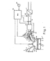
- Figure 1 is a simplified schematic view of a portion of an internal combustion engine with an air intake structure in accordance with a first embodiment of the present invention
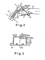
- Figure 2 is an enlarged, simplified longitudinal cross sectional view of a portion of the air intake passage illustrated in Figure 1 in accordance with the first embodiment of the present invention
- Figure 3 is a simplified transverse cross sectional view of the portion of the air intake passage illustrated in Figure 2 in accordance with the first embodiment of the present invention
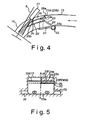
- Figure 4 is an enlarged, simplified longitudinal cross sectional view of a portion of an air intake passage that uses two horizontal plate-like members in accordance with a second embodiment of the present invention
- Figure 5 is a simplified transverse cross sectional view of the portion of the air intake passage illustrated in Figure 4 in accordance with the second embodiment of the present invention
- Figure 6 is an enlarged, simplified longitudinal cross sectional view of a portion of an air intake passage that uses multiple horizontal plate-like members in accordance with a third embodiment of the present invention.
- Figure 7 is a simplified transverse cross sectional view of the portion of the air intake passage illustrated in Figure 6 in accordance with the third embodiment of the present invention.
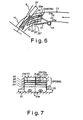
- Figure 8 is a simplified longitudinal cross sectional view of a portion of an air intake passage that uses a plurality of horizontal plate-like members and a plurality of vertical plate-like members that are arranged to form a honeycomb-like structure in accordance with a fourth embodiment of the present invention
- Figure 9 is a simplified transverse cross sectional view of the portion of the air intake passage illustrated in Figure 8 in accordance with the fourth embodiment of the present invention.
- Figure 10 is an enlarged, simplified longitudinal cross sectional view of a portion of the air intake passage in accordance with a fifth embodiment of the present invention.
- Figure 11 is a simplified transverse cross sectional view of the portion of the air intake passage illustrated in Figure 10 in accordance with the fifth embodiment of the present invention.
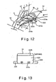
- Figure 12 is an enlarged, simplified longitudinal cross sectional view of a portion of the air intake passage in accordance with a sixth embodiment of the present invention.
- Figure 13 is a simplified transverse cross sectional view of the portion of the air intake passage illustrated in Figure 12 in accordance with the sixth embodiment of the present invention.
- Figure 14 is an enlarged, simplified longitudinal cross sectional view of a portion of the air intake passage in accordance with a seventh embodiment of the present invention.
- Figure 15 is a simplified transverse cross sectional view of the portion of the air intake passage illustrated in Figure 14 in accordance with the seventh embodiment of the present invention.
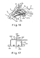
- Figure 16 is an enlarged, simplified longitudinal cross sectional view of a portion of the air intake passage in accordance with an eighth embodiment of the present invention.
- Figure 17 is a simplified transverse cross sectional view of the portion of the air intake passage illustrated in Figure 16 in accordance with the eighth embodiment of the present invention.
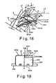
- Figure 18 is an enlarged, simplified longitudinal cross sectional view of a portion of the air intake passage in accordance with a ninth embodiment of the present invention.
- Figure 19 is a simplified transverse cross sectional view of the portion of the air intake passage illustrated in Figure 18 in accordance with the ninth embodiment of the present invention.
- Figure 20 is an enlarged, simplified longitudinal cross sectional view of a portion of the air intake passage in accordance with a tenth embodiment of the present invention.
- Figure 21 is a simplified transverse cross sectional view of the portion of the air intake passage illustrated in Figure 20 in accordance with the tenth embodiment of the present invention.
- the internal combustion engine basically includes a plurality of (e.g., four) cylinders 1 (only one shown in figure) with a piston 2 arranged inside of each of the cylinders 1 to reciprocate in a conventional manner.
- the cylinders 1 are formed in an engine block that has a cylinder head 3 mounted to overlie each of the cylinders 1.
- a top surface 2a of each of the pistons 2 and a portion of the cylinder head 3 above each of the cylinders 1 form a combustion chamber 4.
- a spark plug 5 is arranged in the cylinder head 3 above each of the combustion chambers 4.
- Two intake valves 6 and two exhaust valves 7 are arranged in each of the combustion chambers 4.
- the intake valves 6 and the exhaust valves 7 are opened and closed by a pair of valve operating mechanisms 8 and 9, respectively, in a conventional manner.
- Dual input ports 10 and dual exhaust ports 11 are arranged on opposite sides of each of the combustion chambers 4.
- An intake manifold 12 is connected to each of the air intake ports 10 of each of the combustion chambers 4 so as to form a plurality of intake passages 13 (only one shown in Figure 1 ) for supplying intake air individually to each of the combustion chambers 4.
- an exhaust manifold (not shown) is connected to the exhaust ports 11 of each of the combustion chambers 4 so as to form a plurality of exhaust passages 15 (only one shown in Figure 1 ) for removing exhaust air individually to each of the combustion chambers 4.
- a throttle valve 16 is arranged upstream of the intake manifold 12 to regulate the flow of fresh air into the intake passages 13. Fresh air is drawn in through an air cleaner 17 arranged upstream of the throttle valve 16 in accordance with the open/close control of the throttle valve 16.
- a collector 18 is arranged downstream of the throttle valve 16 and serves to distribute intake air to each of the cylinders 1 through the intake manifold 12, which is connected to the collector 18.
- Each of the intake passages 13 has an air intake control valve 20 disposed therein for deflecting the intake air to one side of the air intake passage 13.
- a portion of the bottom surface of the internal passage wall is provided with a recess or cavity that forms a storage compartment 21 for storing the air intake control valve 20.
- the air intake control valve 20 is pivotally attached to the passage wall of the air intake passage 13 by a valve shaft 22.
- the air intake control valve 20 is a flap valve having the valve shaft 22 arranged in a turnable fashion in a prescribed position of the storage compartment 21.
- the valve shaft 22 forms a pivot or rotational axis that is disposed in a position closely adjacent to the passage wall in a section of the air intake passage 13 (e.g., in the intake manifold 12).
- the rotational axis of the valve shaft 22 is located on a portion of the bottom surface of the passage wall such that the valve shaft 22 is outside of the air flow path of the air intake passage 13.
- the air intake control valve 20 preferably has a plate-like valve element 23 that is fixed to the valve shaft 22 at the inner end 23a thereof.
- the air intake control valve 20 has an outer end 23b with a swirl-producing notch 23c is formed on the right side of the outer end 23b and a free outermost edge 23d formed on the left side of the outer end 23b as seen in Figure 3 .
- the swirl-producing notch 23c is formed on the outer end 23b of the valve element 23 so as to define a bottom edge 23e and a side edge 23f.
- the swirl-producing notch 23c is formed by cutting away a portion of the valve element 23 ranging from a center position (line A-A) to the right side of the valve element 23.
- the valve shaft 22 of the air intake control valve 20 can be turned (rotated) by an actuator 24 (servomotor).
- the opening and closing of the air intake passage 13 is controlled by operating the actuator 24 and, thereby, controlling the rotational position of the valve shaft 22.
- the valve shaft 22 is turned, the free outermost edge 23d of the outer end 23b of the valve element 23 moves along a circular arc (rotational path or arc) centered on the valve shaft 22.
- the air intake control valve 20 is fully open, i.e., when the valve element 23 of the air intake control valve 20 is in a retracted positioned so as to be parallel to the air intake passage 13, the entire air intake control valve 20 is housed in the storage compartment 21. In this fully open state, the flow resistance with respect to the intake air is reduced.
- a horizontal partitioning plate or member 25 is arranged inside the air intake passage 13 (e.g., in the intake port 10) as a member for regulating the flow of the intake air.
- the horizontal partitioning plate 25 is a horizontal plate-like member that is arranged so as to be oriented along the flow direction of the intake air in the air intake passage 13 and configured to have rectifying effect with respect to the flow of the intake air.
- the horizontal partitioning plate 25 is arranged longitudinally within the air intake passage 13 so as to extend along the flow direction of the intake air.
- the horizontal partitioning plate 25 forms a continuous contour with respect to the outer edge (bottom edge 23e) of the side of the outer end 23b of the valve element 23 where the swirl-producing notch 23c is formed.
- the horizontal partitioning plate 25 is arranged so as to extend along the flow direction of the intake air from a position corresponding to the position where the bottom edge 23e formed by the swirl-producing notch 23c of the valve element 23 is located.
- a vertical partitioning plate or member 26 is arranged inside the air intake passage 13 (e.g., in the intake port 10) as a member for controlling the flow of the intake air when the horizontal partitioning plate 25 is moved to a closed state.
- the vertical partitioning plate 26 is a vertical plate-like member that is arranged so as to form an angle (substantially perpendicular angle) with respect to the horizontal partitioning plate 25 in a position corresponding to the side edge 23f formed by the swirl-producing notch 23c formed in the valve element 23.
- the vertical partitioning plate 26 is arranged longitudinally within the air intake passage 13 in such a manner as to extend along the flow direction of the intake air and exists only on the upper side (perpendicularly above) the horizontal partitioning plate 25.
- the vertical partitioning plate 26 is arranged so as to extend along the flow direction of the intake air from a position corresponding to the position where the side edge 23f formed by the swirl-producing notch 23c of the valve element 23 is located.
- the downstream edges of the horizontal and vertical partitioning plates 25 and 26 are located in a vicinity of the combustion chamber 4 (i.e., the vicinity of the intake valve 6).
- the vertical partitioning plate 26 is positioned slightly off the centerline (line A-A) of the valve element 23 of the air intake control valve 20 so that the upstream end or edge 26a on the upstream side of the vertical partitioning plate 26 does not interfere with the side edge 23f when the air intake control valve 20 is opened and closed.
- the upstream front end 26a of the vertical partitioning plate 26 is positioned and configured such that aligns with the side edge 23f of the valve element 23 when the air intake control valve 20 is fully closed, and the downstream end or edge 26b of the vertical partitioning plate 26 is positioned in the vicinity of a fuel injection valve 27 arranged in the air intake passage 13.
- the fuel injection valve 27 is provided in a downstream portion of the air intake passage 13 at a position upstream of the branch point where the air intake passage 13 branches into two intake ports 10.
- the downstream edges of the horizontal and vertical partitioning plates 25 and 26 are located so as not to interfere with the fuel stream of the fuel injection valve 27.
- the horizontal partitioning plate 25 and the vertical partitioning plate 26 are arranged so as to form a substantially perpendicular L shape.
- the plate-like members 25 and 26 are in positions corresponding to the swirl-producing notch 23c formed in the valve element 23 when the air intake control valve 20 is fully closed. Intake air passes through the swirl-producing notch 23c and is guided by the horizontal partitioning plate 25 and the vertical partitioning plate 26 such that the intake air forms a swirl flow inside the cylinder 1 without the flow becoming turbulent.
- an air flow meter 28 (intake air detection sensor) is provided in the air intake passage 13 at a position upstream of the throttle valve 16, and a crank angle sensor 29 is provided to output a signal corresponding to the rotational speed of the engine.
- the actuator 24 i.e., the rotational position of the valve shaft 22
- engine operating conditions such as engine rotational speed detected by these sensors 28 and 29 and or other sensors.
- the output signals of these sensors 28 and 29 are fed to an engine control unit ("ECU") 30, where they are used in various computations and control operations.
- the engine control unit 30 preferably includes a microcomputer with a control program that controls the operation of the engine.
- the engine control unit 30 is configured and programmed to control the spark ignition timing of the spark plugs 5, the opening degree of the throttle valve 16, the actuator 24 (i.e., the rotational position of the valve shaft 22), and the fuel injection from the fuel injection valve 27.
- the engine control unit 30 can also include other conventional components such as an input interface circuit, an output interface circuit, and storage devices such as a ROM (Read Only Memory) device and a RAM (Random Access Memory) device.
- the horizontal partitioning plate 25 and the vertical partitioning plate 26 are configured and arranged to extend along the flow direction of the intake air inside the air intake passage 13, the intake air is delivered into the cylinder 1 in such a manner that a strong swirl flow is produced without causing the gas flow to become turbulent.
- the air intake control valve 20 When the engine is operating in a medium rotational speed/medium load region, the air intake control valve 20 is opened partially to an opening degree that is determined in accordance with the sizes of the rotational speed and the load.
- the air intake control valve 20 When the engine is operating in a high rotational speed/high load region, the air intake control valve 20 is fully opened. When the air intake control valve 20 is fully opened, the air intake control valve 20 (valve element 23) is stored in the storage compartment 21 formed in the bottom surface of the internal passage wall of the air intake passage 13 and the flow resistance with respect to the intake air is reduced.
- the valve shaft 22 when the valve shaft 22 is in a prescribed rotational position (e.g., the position shown in Figure 3 ), the horizontal partitioning plate 25 and the vertical partitioning plate 26 (which extend along the flow direction of the intake air) form a continuous contour with respect to the swirl-producing notch 23c of the valve element 23 of the air intake control valve 20.
- the intake air passing through the air intake control valve 20 can be delivered into the cylinder 1 in a stable manner, enabling exhaust emissions to be greatly reduced and the fuel economy to be improved.
- the horizontal partitioning plate 25 and the vertical partitioning plate 26 form a generally perpendicular L shape in a cross sectional view of the air intake passage 13 lying in a plane perpendicular to the flow direction of the intake air.
- a passage corresponding to the swirl-producing notch 23c is formed and a stable swirl flow can be produced.
- a portion of the air intake passage 13 is cut away (recess) to form the storage compartment 21 for storing the air intake control valve 20.
- the flow resistance with respect to the intake air can be reduced by storing the air intake control valve 20 (valve element 23) in the storage compartment 23.
- an air intake structure is illustrated in accordance with a second embodiment.
- This air intake structure of the second embodiment replaces the air intake structure of the first embodiment that is shown in Figure 1 .
- the air intake structure of the second embodiment is installed in the internal combustion engine of Figure 1 .
- the parts of the second embodiment that are identical to the parts of the first embodiment will be given the same reference numerals as the parts of the prior embodiments.
- the descriptions of the parts of the second embodiment that are identical to the parts of the first embodiments may be omitted for the sake of brevity.
- one supplemental horizontal partitioning plate 25' has been provided such that there are first and second horizontal partitioning plates 25 and 25'.
- Each of the first and second horizontal partitioning plates 25 and 25' are formed as a thin sheet member, arranged so as to be substantially parallel to each other and separated from each other by a prescribed distance in the vertical direction of the air intake passage 13.
- the first and second horizontal partitioning plates 25 and 25' are configured such that they extend outwardly from the vertical partitioning plate 26 in the widthwise direction (rightward side and leftward side from the vertical partitioning plate 26 in Figure 5 ).
- a notch is provided in the leftward extending side portion of each of the first and second horizontal partitioning plates 25 and 25' so that when the valve shaft 22 is rotated, the horizontal partitioning plates 25 and 25' will not interfere with the free outermost edge 23d of the side of the outer end 23b of the valve element 23 where the swirl-producing notch 23c is not formed.
- Each of the notches forms a continuous contour with respect to the free outermost edge 23d of the valve element 23 when the valve shaft 22 is at a prescribed rotational position.
- the upstream ends of the first and second horizontal partitioning plates 25 and 25' are stepped shape to correspond to the stepped shape of the outer end 23b of the valve element 23.
- the vertical partitioning plate 26 is arranged so as to extend downward inside the air intake passage 13 and is connected so as to be perpendicular to the first and second horizontal partitioning plates 25 and 25'. Consequently, the first and second horizontal partitioning plates 25 and 25' form an upside-down T shape with the vertical partitioning plate 26 in a cross sectional view of the air intake passage 13 lying in a plane perpendicular to the flow direction of the intake air. Also, as mentioned above, each of the first and second horizontal partitioning plates 25 and 25' has a notch formed on the leftward extending side portions such that first and second horizontal partitioning plates 25 and 25' will not interfere with the free outermost edge 23d of the side of the outer end 23b of the valve element 23 where the swirl-producing notch 23c is not formed.
- the air intake control valve 20 when the engine is operating in a low rotational speed/low load region, the air intake control valve 20 is closed fully to deliver the intake air into the cylinder 1 in such a manner that a strong swirl flow is produced.
- the air intake control valve 20 When the engine is operating in a medium rotational speed/medium load region, the air intake control valve 20 is opened partially.
- the first horizontal partitioning plate 25 forms a continuous contour with respect to the free outermost edge 23d of the side (portion) of the outer end 23b of the valve element 23 where the swirl-producing notch 23c is not formed and the second horizontal partitioning plate 25' forms a continuous contour with respect to the bottom edge 23e of the side (portion) of the outer end 23b of the valve element 23 where the swirl-producing notch 23c is formed.
- the intake air is directed into the cylinder 1 through an opening section comprising the passages located above the first horizontal partitioning plate 25 (the passages located to the left and right sides of the vertical partitioning plate 26 in Figure 5 ) and the passage formed by the first horizontal partitioning plate 25, the second horizontal partitioning plate 25' and the vertical partitioning plate 26.
- first horizontal partitioning plate 25, the second horizontal partitioning plate 25', and the vertical partitioning plate 26 are all configured to follow the contour of the flow of intake air through the air intake passage 13, a swirl motion can be produced without causing the flow of the intake air to become turbulent when the air intake control valve 20 is set to this intermediate opening degree. As a result, exhaust emissions can be greatly reduced and the fuel economy can be improved.
- the air intake control valve 20 When the engine is operating in a high rotational speed/high load region, the air intake control valve 20 is opened fully in the same manner as the first embodiment as seen in Figure 3 . When the air intake control valve 20 is fully opened, the air intake control valve 20 (valve element 23) is stored in the storage compartment 21 and the flow resistance with respect to the intake air is reduced.
- this second embodiment illustrates an example in which there are two horizontal plate-like members, i.e., the first horizontal partitioning plate 25 and the second horizontal partitioning plate 25', the present invention is not limited to this number of horizontal plate-like members.
- an air intake structure is illustrated in accordance with a third embodiment.
- This air intake structure of the third embodiment replaces the air intake structure of the first embodiment that is shown in Figure 1 .
- the air intake structure of the third embodiment is installed in the internal combustion engine of Figure 1 .
- the parts of the third embodiment that are identical to the parts of the prior embodiments will be given the same reference numerals as the parts of the prior embodiments.
- the descriptions of the parts of the third embodiment that are identical to the parts of the prior embodiments may be omitted for the sake of brevity.
- the air intake structure can be provided with a plurality (four) of horizontal partitioning plates 25, 25', 25" and 25"'.
- the opening degree of the air intake control valve 20 can be controlled to anyone of a plurality of prescribed intermediate opening degrees based on the operating conditions (rotational speed and load) of the internal combustion engine, the prescribed opening degrees corresponding to rotational positions of the valve shaft 22 where the free outermost edge 23d of the valve element 23 each form a continuous contour with respect to a horizontal partitioning plate 25 such that a stable gas flow is produced without the flow of the intake air becoming turbulent.
- FIG. 8 and 9 an air intake structure is illustrated in accordance with a fourth embodiment.
- This air intake structure of the fourth embodiment replaces the air intake structure of the first embodiment that is shown in Figure 1 .
- the air intake structure of the fourth embodiment is installed in the internal combustion engine of Figure 1 .
- the parts of the fourth embodiment that are identical to the parts of the prior embodiments will be given the same reference numerals as the parts of the prior embodiments.
- the descriptions of the parts of the fourth embodiment that are identical to the parts of the prior embodiments may be omitted for the sake of brevity.
- Figures 8 and 9 shows another example in which multiple horizontal partitioning plates 125 and multiple vertical partitioning plates 126 are provided so as to form a honeycomb-like structure.
- This structure too, enables a stable gas flow to be produced without causing the intake air flow to become turbulent.
- the flow resistance against the intake air can be reduced by making the horizontal partitioning plates 125 and vertical partitioning plates 126 out of a thin sheet-like material.
- the horizontal partitioning plates 125 lie in planes generally parallel to the flow direction of the intake air, while the vertical partitioning plates 126 in planes generally parallel to the flow direction but perpendicular to the horizontal partitioning plates 125.
- each of the horizontal partitioning plates 125 is provided with a notch formed such that when the valve shaft 22 is rotated, the horizontal partitioning plates 125 will not interfere with the free outermost edge 23d of the side of the outer end 23b of the valve element 23 where the swirl-producing notch 23c is not formed. As a result, the valve element 23 does not interfere with (bump into) the horizontal partitioning plates 125 when the air intake control valve 20 is rotated.
- At least one supplemental horizontal plate-like member is provided so as to be substantially perpendicular to the vertical partitioning plate 26 and arranged to extend along the intake air flow direction from a position corresponding to the outside edge (23d, 23e) of the other end of the air intake control valve 20 (i.e., the end of the valve element 23 that is not connected to the valve shaft 22).
- the free outermost edge 23d of the side of the valve element 23 of the air intake control valve 20 where the swirl-producing notch 23c is not formed and the outer edge (bottom edge 23e) of the side of the valve element 23 of the air intake control valve 20 where the swirl-producing notch 23c is formed are each aligned with a different one of the horizontal partitioning plates 125.
- the vertical partitioning plates 126 and the horizontal partitioning plates 125 form a section having a honeycomb-like structure.
- a stable gas flow can be produced at all times by adjusting the opening degree of the air intake control valve 20 in accordance with the operating conditions.
- the horizontal partitioning plates 125 are arranged and configured such that one of the horizontal partitioning plates 125 forms a continuous contour with respect to the free outermost edge 23d of the side of the other end of the valve element where the swirl-producing notch 23c is not formed when the valve shaft 22 is in a first prescribed rotational position, and a second of the horizontal partitioning plates 125 forms a continuous contour with respect to the bottom edge 23e of the side of the outer end 23b of the valve element 23 where the swirl-producing notch 23c is formed when the valve shaft 22 is in the prescribed rotational position.
- the first horizontal partitioning plates 125 are connected together by the vertical partitioning plates 126.
- an air intake structure is illustrated in accordance with a fifth embodiment.
- This air intake structure of the fifth embodiment replaces the air intake structure of the first embodiment that is shown in Figure 1 .
- the air intake structure of the fifth embodiment is installed in the internal combustion engine of Figure 1 .
- the parts of the fifth embodiment that are identical to the parts of the prior embodiments will be given the same reference numerals as the parts of the prior embodiments.
- the descriptions of the parts of the fifth embodiment that are identical to the parts of the prior embodiments may be omitted for the sake of brevity.
- an air intake control valve 220 (which is a tumble control valve in this embodiment) is moveably mounted to the air intake passage 13 for movement between a storage or open position within a storage compartment 221 of the air intake passage 13 and an air deflecting or closed position.
- the air intake control valve 220 includes a valve shaft 222 that supports a valve element 223.
- the air intake control valve 220 differs from the air intake control valve 20 of the prior embodiments in that there is no notch at the outer edge of the valve element 223.
- the air intake control valve 220 is a flap valve in which the valve shaft 222 is arranged in a turnable fashion from a prescribed position within a storage compartment 221 to an extended position that deflects the intake air to one side of the air intake passage 13.
- the valve element 223 is a rectangular plate-like element that is fixed to the valve shaft 222 at one end 223a thereof such it can turn about the rotational axis of the valve shaft 222.
- the other (free) end 223b of the valve element 223 is configured to be parallel to the upper wall of the air intake passage 13 and serves to control the gas flow in accordance with the rotational position of the valve element 223.
- a horizontal partitioning plate 225 is mounted to the free end 223b of the valve element 223 such that the valve element 223 and the horizontal partitioning plate 225 move together between the storage or open position within the storage compartment 221 of the air intake passage 13 and the air deflecting or closed position.
- the horizontal partitioning plate 225 is a horizontal plate-like member that is arranged so as to be oriented along the flow direction of the intake air in the air intake passage 13 and configured to have rectifying effect with respect to the flow of the intake air.
- the horizontal partitioning plate 225 is coupled at its upstream end to the free end 223b of the valve element 223 of the air intake control valve 220 in a freely pivoting manner.
- the free end 223b of the valve element 223 of the air intake control valve 220 is configured for coupling the horizontal partitioning plate 225 thereto.
- a link member 225a configured to function as a linking mechanism is arranged in such a manner as to maintain the horizontal partitioning plate 225 generally parallel to the upper wall of the air intake passage 13 (intake port 10).
- a four bar linkage is formed by the interconnections of the storage compartment 221, the valve element 223, the horizontal partitioning plate 225 and the link member 225a.
- the link member 225a has an outer coupling end 225b that is coupled in a freely pivoting manner to the side of the horizontal partitioning plate 225 that is downstream of the valve element 223 of the air intake control valve 220.
- the end 225b of the link member 225a is configured as a coupling means for coupling to the other end (i.e., downstream end) of horizontal partitioning plate 225.
- the link member 225a is arranged to pivot about the inner end 225c thereof when the valve element 223 of the air intake control valve 220 rotates. Meanwhile, the horizontal partitioning plate 225 moves in such a manner as to remain substantially oriented along the flow direction of the intake air, i.e., parallel to the flow direction of the intake air (i.e., to the upper wall of the air intake passage 13). As shown in Figure 10 , the inner end 225c of the link member 225a is abutted against a step-like part 221a formed in the storage compartment 221.
- the link member 225a is parallel to the valve element 223 of the air intake control valve 220.
- the valve shaft 222 of the air intake control valve 220 can be turned (rotated) by the actuator 24 (servomotor).
- the opening and closing of the air intake passage 13 is controlled by controlling the actuator 24 and, thereby, controlling the rotational position of the valve shaft 222.
- the valve shaft 222 is turned, the free end 223b of the valve element 223 of the air intake control valve 220 moves along a circular arc centered on the valve shaft 222.
- the intake air is directed into the cylinder 1 (see Figure 1 ) from the opening section formed between the free end 223b of the valve element 223 of the air intake control valve 220 and the upper wall of the air intake passage 13, thereby producing a tumble flow.
- the air intake control valve 220 when the air intake control valve 220 is fully open, i.e., when the valve element 223 of the air intake control valve 220 is positioned so as to be parallel to the air intake passage 13, the valve element 223 is housed in the storage compartment 221. In this state, the flow resistance with respect to the intake air is reduced because the entire air intake control valve 220 is stored inside the storage compartment 221.
- the air intake control valve 220 When the internal combustion engine is operating in a low rotational speed/low load region or a medium rotational speed/medium load region, the air intake control valve 220 is opened partially.
- the opening degree of the air intake control valve 220 under such conditions is determined based on the rotational speed and the load.
- the horizontal partitioning plate 225 moves up and down in accordance with the opening degree of the air intake control valve 220 while remaining parallel to the upper wall of the air intake passage 13 (intake port 10).
- the horizontal partitioning plate 225 rectifies the intake air flow from a position corresponding to the operating conditions, enabling appropriate exhaust, fuel consumption, and output to be obtained simultaneously.
- the tumble flow can be strengthened in regions of low rotational speed and low load.
- the air intake control valve 220 When the internal combustion engine is operating in a high rotational speed/high load region, the air intake control valve 220 is opened fully such that the air intake control valve 220, the horizontal partitioning plate 225, and the link member 225a, are stored inside the storage compartment 221 formed in the lower wall face of the air intake passage 13. Under these conditions, the flow resistance with respect to the intake air is reduced.
- the opening degree of the air intake control valve 220 based on the temperature of the engine coolant. In such a case, the air intake control valve 220 would be closed to produce a strong tumble flow when the coolant temperature is low (i.e., when engine is cool) and opened so as to be stored in the storage compartment 221 when the coolant temperature is high (i.e., when engine is warm).
- the link member 225a is arranged in such manner as to be parallel to the valve element 223 of the air intake control valve 220. As a result, the position of the horizontal partitioning plate 225 can be raised and lowered in a stable manner.
- the horizontal partitioning plate 225 can be kept parallel to the upper wall of the air intake passage 13 when it is moved by the linkage mechanism.
- an air intake structure is illustrated in accordance with a sixth embodiment.
- This air intake structure of the sixth embodiment replaces the air intake structure of the first embodiment that is shown in Figure 1 .
- the air intake structure of the sixth embodiment is installed in the internal combustion engine of Figure 1 .
- This air intake structure of the sixth embodiment is most similar to the fifth embodiment.
- the parts of the sixth embodiment that are identical to the parts of the prior embodiments will be given the same reference numerals as the parts of the prior embodiments.
- the descriptions of the parts of the sixth embodiment that are identical to the parts of the prior embodiments may be omitted for the sake of brevity.
- the air intake control valve 220 is identical to the fifth embodiment, except for the geometry of the four bar linkage formed by the interconnections of the storage compartment 221, the valve element 223, the horizontal partitioning plate 225 and the link member 225a.
- the sum (A + C) of the length C of the link member 225a (from the outer coupling end 225b to the inner end 225c) and the length A from the valve shaft 222 of the air intake control valve 220 to the inner end 225c of the link member 225a is approximately equal to the sum (B + D) of the length D of the air intake control valve 220 and the length B from the coupling end 223b between the air intake control valve 220 and the horizontal partitioning plate 225 to the outer coupling end 225b between the horizontal partitioning plate 225 and the link member 225a (i.e., A + C ⁇ B + D).
- the length A from the valve shaft 222 of the air intake control valve 220 to the inner end 225c of the link member 225a is smaller than the length B from the coupling end 223b between the air intake control valve 220 and the horizontal partitioning plate 225 to the outer coupling end 225b between the horizontal partitioning plate 225 and the link member 225a (i.e., A ⁇ B).
- the sum (A + C) of the length C of the link member 225a and the length A from the valve shaft 222 of the air intake control valve 220 to the inner end 225c of the link member 225a is smaller than the sum (B + D) of the length D of the air intake control valve 220 and the length B from the coupling end 223b between the air intake control valve 220 and the horizontal partitioning plate 225 to the outer coupling end 225b between the horizontal partitioning plate 225 and the link member 225a (i.e., A + C ⁇ B + D).
- the linkage mechanism is thus configured such that the horizontal partitioning plate 225 is farther from the air intake passage 13 (intake port 10) when the air intake control valve 220 is open.
- This arrangement is particularly useful when the engine is configured such that the bottom wall of the air intake passage 13 is curved because the horizontal partitioning plate 225 can be aligned with the air intake passage 13 when the air intake control valve 220 is open without providing a step-like part.
- the linkage mechanism such that the sum (A + C) of the length C of the link member 225a and the length A from the valve shaft 222 of the air intake control valve 220 to the inner end 225c of the link member 225a is smaller than the sum (B + D) of the length D of the air intake control valve 220 and the length B from the coupling end 223b between the air intake control valve 220 and the horizontal partitioning plate 225 to the outer coupling end 225b between the horizontal partitioning plate 225 and the link member 225a (i.e., A + C > B + D).
- the linkage mechanism would thus be configured such that the horizontal partitioning plate 225 is pushed toward the upper wall of the air intake passage 13 (intake port 10) when the air intake control valve 220 is open.
- the horizontal partitioning plate 225 is pushed toward the upper wall of the air intake passage 13 (intake port 10) when the air intake control valve 220 is open.
- an air intake structure is illustrated in accordance with a seventh embodiment.
- This air intake structure of the seventh embodiment replaces the air intake structure of the first embodiment that is shown in Figure 1 .
- the air intake structure of the seventh embodiment is installed in the internal combustion engine of Figure 1 .
- This air intake structure of the seventh embodiment uses the valve element of the first embodiment and the moveable horizontal partitioning plate with the four bar linkage of the fifth embodiment.
- the parts of the seventh embodiment that are identical to the parts of the prior embodiments will be given the same reference numerals as the parts of the prior embodiments.
- the descriptions of the parts of the seventh embodiment that are identical to the parts of the prior embodiments may be omitted for the sake of brevity.
- an air intake control valve 320 is the same as the fifth embodiment, except for the valve element 223 has been replaced with the valve element 323 that is identical to the valve element 23 of the first embodiment.
- the air intake control valve 320 is a swirl control valve having the swirl-producing notch (cut out portion) 323c formed on the right side of the outer end 323b of the valve element 323, the swirl-producing notch 323c being configured so as to provide the valve element 323 with a bottom edge 323e and a side edge 323f.
- the swirl-producing notch 323c is formed on the half of the outer end 323b of the valve element 323 located on the right side of the centerline of the valve element 323 (line A-A).
- the free outermost edge 323d of the side of the other end of the valve element 323 where the swirl-producing notch 323c is not formed is positioned farther from the valve shaft 222 than the bottom edge 323e formed by the swirl-producing valve 320.
- the horizontal partitioning plate 225 is coupled in a freely pivoting manner the air intake control valve 320 at a position corresponding to the bottom edge 323e formed by the swirl-producing notch 323.
- a notch (not shown) is provided in the horizontal partitioning plate 225 so that the free outermost edge 323d of the side of the other end of the valve element 323 where the swirl-producing notch 323c is not formed will not interfere with the horizontal partitioning plate 225 when the air intake control valve 320 is fully open (i.e., when the air intake control valve 320 is stored in the storage compartment 221).
- the length D of the air intake control valve 320 i.e., length from the valve shaft 222 to the inner end 225c
- the air intake control valve 320 When the engine is operating in a low rotational speed/low load region, the air intake control valve 320 is closed fully (i.e., the air intake control valve 320 is at maximum slant angle). When the air intake control valve 320 is fully closed, the free outermost edge 323d of the side of the other end of the valve element 323 where the swirl-producing notch 323c is not formed touches against the upper wall of the air intake passage 13. Due to the horizontal partitioning plate 225, the intake air that passes through the swirl-producing notch 323c of the air intake control valve 320 is delivered into the cylinder 1 (see Figure 1 ) the gas flow becoming turbulent. As a result, a strong swirl flow is produced.
- the air intake control valve 320 When the engine is operating under in a medium rotational speed/medium load region, the air intake control valve 320 is opened partially (not shown) to an opening degree determined in accordance with the sizes of the rotational speed and the load. As a result, the opening degree of the air intake passage 13 can be varied in a continuously variable manner and turbulent gas flow can be prevented even at intermediate opening degrees of the air intake control valve 320.
- the air intake control valve 320 When the engine is operating in a high rotational speed/high load region, the air intake control valve 320 is closed fully. When the air intake control valve 320 is fully closed, the air intake control valve 320 (valve element 323) is stored in the storage compartment 221 formed in the bottom wall of the air intake passage 13 and the flow resistance with respect to the intake air is reduced.
- an air intake structure is illustrated in accordance with an eighth embodiment.
- This air intake structure of the eighth embodiment replaces the air intake structure of the first embodiment that is shown in Figure 1 .
- the air intake structure of the eighth embodiment is installed in the internal combustion engine of Figure 1 .
- This air intake structure of the eighth embodiment uses the valve element of the first embodiment and the moveable horizontal partitioning plate with the four bar linkage of the sixth embodiment.
- the parts of the eighth embodiment that are identical to the parts of the prior embodiments will be given the same reference numerals as the parts of the prior embodiments.
- the descriptions of the parts of the eighth embodiment that are identical to the parts of the prior embodiments may be omitted for the sake of brevity.
- an air intake control valve 320 has a four bar linkage in which the sum (A + C) of the length C of the link member 225a and the length A from the valve shaft 222 of the air intake control valve 320 to the inner end 225c of the link member 225a is approximately equal to the sum (B + D) of the length D of the air intake control valve 320 (from the valve shaft 222 to the coupling end 323b) and the length B from the coupling end 323b between the air intake control valve 320 and the horizontal partitioning plate 225 to the outer coupling end 225b between the horizontal partitioning plate 225 and the link member 225a (i.e., A + C ⁇ B + D) and the length A from the valve shaft 222 of the air intake control valve 320 to the inner end 225c of the link member 225a is smaller than the length B from the coupling end 323b between the air intake control valve 320 and the horizontal partitioning plate 225 to the
- the sum (A + C) of the length C of the link member 225a and the length A from the valve shaft 222 of the air intake control valve 320 to the inner end 225c of the link member 225a is smaller than the sum (B + D) of the length D of the air intake control valve 320 and the length B from the coupling end 323b between the air intake control valve 320 and the horizontal partitioning plate 225 to the outer coupling end 225b between the horizontal partitioning plate 225 and the link member 225a (i.e., A + C ⁇ B + D).
- the linkage mechanism is thus configured such that the horizontal partitioning plate 225 is farther from the air intake passage 13 (intake port 10) when the air intake control valve 320 is open.
- This arrangement is particularly useful when the engine is configured such that the bottom wall of the air intake passage 13 is curved because the horizontal partitioning plate 225 can be aligned with the air intake passage 13 when the air intake control valve 320 is open without providing a step-like part.
- the linkage mechanism such that the sum (A + C) of the length C of the link member 225a and the length A from the valve shaft 222 of the air intake control valve 320 to the inner end 225c of the link member 225a is smaller than the sum (B + D) of the length D of the air intake control valve 320 and the length B from the coupling end 323b between the air intake control valve 320 and the horizontal partitioning plate 225 to the outer coupling end 225b between the horizontal partitioning plate 225 and the link member 225a (i.e., A + C > B + D).
- the linkage mechanism would thus be configured such that the horizontal partitioning plate 225 is pushed toward the upper wall of the air intake passage 13 (intake port 10) when the air intake control valve 320 is open.
- Such an arrangement is particularly useful when the engine is configured such that the bottom wall of the air intake passage 13 has a straighter shape because the horizontal partitioning plate 225 can be aligned with the air intake passage 13 when the air intake control valve 320 is open without providing a step-like part.
- FIG. 18 an air intake structure is illustrated in accordance with a ninth embodiment.
- This air intake structure of the ninth embodiment replaces the air intake structure of the first embodiment that is shown in Figure 1 .
- the air intake structure of the ninth embodiment is installed in the internal combustion engine of Figure 1 .
- This air intake structure of the ninth embodiment has an air intake control valve 320 that is identical to the air intake control valve 320 of the seventh embodiment, except that a moveable vertical partitioning plate 226 has been added and a modified storage compartment 221' is used to accommodate the vertical partitioning plate 226.
- the air intake control valve 320 has the vertical partitioning plate 226 mounted on the outer coupling end 323b of the valve element 323.
- the vertical partitioning plate 226 moves together with the valve element 323.
- the vertical partitioning plate 226 is arranged to extend along the flow direction of the intake air from the side edge 323f (centerline of valve element 323 (line A-A)) formed by the swirl-producing notch 323c of the valve element 323 of the air intake control valve 320.
- the vertical partitioning plate 226 turns integrally with the valve element 323 when the valve element 323 turns about the valve shaft 222 (see Figure 18 ).
- the storage compartment 221' is provided with a step portion 221a' as in some of the prior embodiments and a groove 221b' with a shape corresponding to the vertical partitioning plate 226 that serves to store the vertical partitioning plate 226 in the storage compartment 221' when the air intake control valve 320 is fully closed.
- the length D of the air intake control valve 320 i.e., length from the valve shaft 22 to the inner end 225c
- the length C of the link member 225a D).
- an air intake structure is illustrated in accordance with a tenth embodiment.
- This air intake structure of the ninth embodiment has an air intake control valve 320 that is identical to the air intake control valve 320 of the eighth embodiment, except that a moveable vertical partitioning plate 226 has been added, similar to the ninth embodiment.
- the air intake control valve 320 that is identical to the air intake control valve 320 of the ninth embodiment, except that the four bar linkage of this embodiment uses the geometry of the eighth embodiment.
- the air intake structure of the tenth embodiment replaces the air intake structure of the first embodiment that is shown in Figure 1 .
- the air intake structure of the tenth embodiment is installed in the internal combustion engine of Figure 1 .
- the air intake control valve 320 has the vertical partitioning plate 226 mounted on the outer coupling end 323b of the valve element 323, similar to the ninth embodiment.
- the horizontal partitioning plate 225 and vertical partitioning plate 226 move together with the valve element 323.
- the air intake control valve 320 has a four bar linkage in which the sum (A + C) of the length C of the link member 225a and the length A from the valve shaft 222 of the air intake control valve 320 to the inner end 225c of the link member 225a is approximately equal to the sum (B + D) of the length D of the air intake control valve 320 and the length B from the coupling end 323b between the air intake control valve 320 and the horizontal partitioning plate 225 to the outer coupling end 225b between the horizontal partitioning plate 225 and the link member 225a (i.e., A + C ⁇ B + D) and the length A from the valve shaft 222 of the air intake control valve 320 to the inner end 225c of the link member 225a is smaller than the length B from the coupling end 323b between the air intake control valve 320 and the horizontal partitioning plate 225 to the outer coupling end 225b between the horizontal partitioning plate
- the sum (A + C) of the length C of the link member 225a and the length A from the valve shaft 222 of the air intake control valve 320 to the inner end 225c of the link member 225a is smaller than the sum (B + D) of the length D of the air intake control valve 320 and the length B from the coupling end 323b between the air intake control valve 320 and the horizontal partitioning plate 225 to the outer coupling end 225b between the horizontal partitioning plate 225 and the link member 225a (i.e., A + C ⁇ B + D).
- the linkage mechanism is thus configured such that the horizontal partitioning plate 225 is farther from the air intake passage 13 (intake port 10) when the air intake control valve 320 is open.
- This arrangement is particularly useful when the engine is configured such that the bottom wall of the air intake passage 13 is curved because the horizontal partitioning plate 225 can be aligned with the air intake passage 13 when the air intake control valve 320 is open without providing a step-like part.
- the linkage mechanism such that the sum (A + C) of the length C of the link member 225a and the length A from the valve shaft 222 of the air intake control valve 320 to the inner end 225c of the link member 225a is smaller than the sum (B + D) of the length D of the air intake control valve 320 and the length B from the coupling end 323b between the air intake control valve 320 and the horizontal partitioning plate 225 to the outer coupling end 225b between the horizontal partitioning plate 225 and the link member 225a (i.e., A + C > B + D).
- the linkage mechanism would thus be configured such that the horizontal partitioning plate 225 is pushed toward the upper wall of the air intake passage 13 (intake port 10) when the air intake control valve 320 is open.
- Such an arrangement is particularly useful when the engine is configured such that the bottom wall of the air intake passage 13 has a straighter shape because the horizontal partitioning plate 225 can be aligned with the air intake passage 13 when the air intake control valve 320 is open without providing a step-like part.
Landscapes
- Engineering & Computer Science (AREA)
- Chemical & Material Sciences (AREA)
- Combustion & Propulsion (AREA)
- Mechanical Engineering (AREA)
- General Engineering & Computer Science (AREA)
- Control Of Throttle Valves Provided In The Intake System Or In The Exhaust System (AREA)
- Cylinder Crankcases Of Internal Combustion Engines (AREA)
Claims (16)
- Brennkraftmaschinen- Lufteinlassstruktur, aufweisend:einen Lufteinlasskanal (13) mit einer inneren Kanalwand,ein Lufteinlass- Steuerventil (20), angeordnet in dem Lufteinlasskanal (13), um sich wahlweise zwischen einer zurückgezogenen Position und einer Einlassluft-Ablenkungsposition um eine Drehachse zu bewegen, die auf einer Seite des Lufteinlasskanals (13) in einer Position nahe benachbart zu der inneren Kanalwand des Lufteinlasskanals (13) positioniert ist, wobei das Lufteinlass- Steuerventil (20) ein Ventilelement (23) mit einem inneren Ende, angeordnet auf der Drehachse, und ein äußeres Ende mit einer wirbel- erzeugenden Aussparung (23c) mit einer Bodenkante (23e) und einer Seitenkante (23f) enthält;ein erstes Trennteil (25), längs innerhalb des Lufteinlasskanals (13) angeordnet, um sich im Wesentlichen parallel zu einer Strömungsrichtung der Einlassluft von einer Position entsprechend der Bodenkante (23e), gebildet durch die wirbel- erzeugenden Aussparung (23c) des Ventilelementes (23), zu erstrecken, wenn das Lufteinlass- Steuerventil (20) in der Einlassluft- Ablenkungsposition ist; und dadurch gekennzeichnet, dassein zweites Trennteil (26) angeordnet ist, um einen Winkel in Bezug auf das erste Trennteil (25) zu bilden und sich entlang der Strömungsrichtung der Einlassluft von der Seitenkante, gebildet durch die wirbel- erzeugende Aussparung (23c) des Ventilelements (23), zu erstrecken, wenn das Lufteinlass- Steuerventil (20) in der Einlassluft- Ablenkungsposition ist.
- Brennkraftmaschinen- Lufteinlassstruktur nach Anspruch 1, wobei das erste Trennteil (25) und das zweite Trennteil (26) eine im Wesentlichen rechtwinklige L- Form bilden, wenn in einer Querschnittsansicht des Lufteinlasskanals (13) gesehen, genommen entlang einer Ebene rechtwinklig zu der Strömungsrichtung der Einlassluft.
- Brennkraftmaschinen- Lufteinlassstruktur nach Anspruch 1, wobei das erste Trennteil (25) konfiguriert und angeordnet ist, sich in einer Richtung der Breite zu erstrecken und eine umgekehrte T- Form mit dem zweiten Trennteil (26) zu bilden, wenn in einer Querschnittsansicht des Lufteinlasskanals (13) gesehen, genommen entlang einer Ebene rechtwinklig zu der Strömungsrichtung der Einlassluft, und
das erste Trennteil (25) eine derart gebildete Aussparung enthält derart, dass das erste Trennteil (25) nicht mit einer Außenkante des Ventilelements (23), wo die wirbel- erzeugende Aussparung (23c) nicht gebildet ist, stört, wenn das Lufteinlass- Steuerventil (20) in die Einlassluft- Ablenkungsposition gedreht wird. - Brennkraftmaschinen- Lufteinlassstruktur nach einem der Ansprüche 1 bis 3, außerdem aufweisend
zumindest ein ergänzendes Trennteil (25', 125), angeordnet im Wesentlichen rechtwinklig zu dem zweiten Trennteil (26) und sich entlang der Strömungsrichtung der Einlassluft von einer Position erstreckend, die der Bodenkante (23e), gebildet durch die wirbel- erzeugende Aussparung (23c) des Ventilelements (23) entspricht, wenn das Lufteinlass- Steuerventil (20) in einer dazwischenliegenden, vorbeschriebenen Einlassluft- Ablenkungsposition ist. - Brennkraftmaschinen- Lufteinlassstruktur nach Anspruch 4, wobei das erste Trennteil (25), das zweite Trennteil (26) und das zumindest eine ergänzende Trennteil (25', 125) angeordnet sind, um eine wabenartige Struktur (31) zu bilden.
- Brennkraftmaschinen- Lufteinlassstruktur nach Anspruch 1, außerdem aufweisend
zumindest ein ergänzendes Trennteil (25', 125), im Wesentlichen parallel zu dem ersten Trennteil (25) angeordnet und sich entlang der Strömungsrichtung der Einlassluft erstreckend,
wobei das erste Trennteil (25) angeordnet und konfiguriert ist, eine fortlaufende Kontur in Bezug auf eine Außenkante des äußeren Endes des Ventilelements (23) zu bilden, wo die wirbel- erzeugende Aussparung (23c) nicht gebildet ist, wenn das Lufteinlass- Steuerventil (20) in einer dazwischenliegenden, vorbeschriebenen Einlassluft- Ablenkungsposition ist,
wobei das zumindest eine ergänzende Trennteil (25', 125) angeordnet und konfiguriert ist, eine fortlaufende Kontur in Bezug auf eine Bodenkante (23e) der wirbel- erzeugenden Aussparung (23c) zu bilden, wenn das Lufteinlass- Steuerventil (20) in der dazwischenliegenden, vorbeschriebenen Einlassluft- Ablenkungsposition ist, und
das erste Trennteil (25) und das zumindest eine ergänzende Trennteil (25', 125) miteinander durch das zweite Trennteil (26) verbunden sind. - Brennkraftmaschinen- Lufteinlassstruktur nach einem der Ansprüche 1 bis 6, wobei
das zweite Trennteil (26) eine stromaufseitige Vorderkante hat, die mit der Seitenkante, gebildet durch die wirbel- erzeugende Aussparung (23c), ausgerichtet ist, wenn das Lufteinlass- Steuerventil (20) in der Einlassluft- Ablenkungsposition ist. - Brennkraftmaschinen- Lufteinlassstruktur nach einem der Ansprüche 1, 2 und 7, wobei
das erste Trennteil (225) mit einem stromaufwärtigen Teil des Ventilelements (223) an einem Verbindungspunkt verbunden ist, und
wobei das erste Trennteil (25) durch ein erstes Ende eines Verbindungsteiles (225a) in einer freischwenkbaren Weise verbunden ist, um eine äußere Schwenkachse zu bilden, wobei das Verbindungsteil (225a) konfiguriert ist, das erste Trennteil (225) im Wesentlichen ausgerichtet entlang der Strömungsrichtung der Einlassluft beizubehalten, wenn das Lufteinlass- Steuerventil (20) zwischen der zurückgezogenen Position und der Einlassluft- Ablenkungsposition bewegt wird. - Brennkraftmaschinen- Lufteinlassstruktur nach Anspruch 8, wobei
das Verbindungsteil (225a) ein zweites Ende hat, schwenkbar in Bezug auf die innere Kanalwand des Lufteinlasskanals (13) montiert, um eine innere Schwenkachse zu bilden, und das Verbindungsteil (225a) parallel zu dem Ventilelement (223) des Lufteinlass- Steuerventils (220) angeordnet ist. - Brennkraftmaschinen- Lufteinlassstruktur nach Anspruch 8 oder 9, wobei
die Drehachse des Lufteinlass- Steuerventils (220) von der inneren Drehachse des Verbindungsteils (225a) um eine erste Länge (A) beabstandet ist, die im Wesentlichen gleich ist zu einer zweiten Länge (B) zwischen dem Verbindungspunkt, gebildet zwischen dem Ventilelement (223) und dem ersten Trennteil (225) und der äußeren Schwenkachse, gebildet zwischen dem ersten Trennteil (225) und dem Verbindungsteil (225a). - Brennkraftmaschinen- Lufteinlassstruktur nach einem der Ansprüche 8 bis 10, wobei
das Ventilelement (223) eine Länge (D) hat, wenn zwischen der Drehachse des Lufteinlass- Steuerventils (220) und dem ersten Trennteil (225) gemessen, die im Wesentlichen gleich ist zu einer Länge (C) des Verbindungsteils (225a), wenn gemessen zwischen der äußeren Schwenkachse, gebildet zwischen dem ersten Trennteil (225) und dem Verbindungsteil (225a) und der inneren Schwenkachse des Verbindungsteiles (225a). - Brennkraftmaschinen- Lufteinlassstruktur nach Anspruch 8 oder 9, wobei
die Drehachse des Lufteinlass- Steuerventils (220) durch eine erste Länge (A) beabstandet ist von der inneren Schwenkachse des Verbindungsteiles (225a), die kürzer ist als eine zweite Länge (B) zwischen dem Verbindungspunkt, gebildet zwischen dem Ventilelement (223) und der äußeren Schwenkachse, gebildet zwischen dem ersten Trennteil (225) und dem Verbindungsteil (225a). - Brennkraftmaschinen- Lufteinlassstruktur nach Anspruch 8 oder 9, wobei
die Drehachse des Lufteinlass- Steuerventils (220) von der inneren Schwenkachse des Verbindungsteils (225a) um eine erste Länge (A) beabstandet ist,
der Verbindungspunkt, gebildet zwischen dem Ventilelement (223) und dem ersten Trennteil (225) und der äußeren Schwenkachse beabstandet ist von der äußeren Schwenkachse, gebildet zwischen dem ersten Trennteil (2259 und dem Verbindungsteil (225a), um eine zweite Länge (B),
wobei das Verbindungsteil (225a) eine Länge (C) hat, wenn gemessen zwischen der äußeren Schwenkachse, gebildet zwischen dem ersten Trennteil (25) und dem Verbindungsteil (225a) und der inneren Schwenkachse des Verbindungsteils (225a),
das Ventilelement (223) eine Länge (D) hat, wenn gemessen zwischen der Drehachse des Lufteinlass- Steuerventils (20) und dem ersten Trennteil (225) und die Summe (A+C) der Länge (C) des Verbindungsteiles (225a) und die erste Länge (A) zwischen der Drehachse des Lufteinlass- Steuerventils (20) und der inneren Schwenkachse des Verbindungsteils (225a) kleiner ist als die Summe (B + D) der Länge (D) des Ventilelements (223) und der zweiten Länge (B) zwischen der äußeren Schwenkachse und dem Verbindungspunkt, gebildet zwischen dem Ventilelement (223) und dem ersten Trennteil (225). - Brennkraftmaschinen- Lufteinlassstruktur nach Anspruch 8 oder 9, wobei
die Drehachse des Lufteinlass- Steuerventils (20) von der inneren Schwenkachse de Verbindungsteils (225a) um eine erste Länge (A) beabstandet ist,
der Verbindungspunkt, gebildet zwischen dem Ventilelement (223) und dem ersten Trennteil (225) und der äußeren Schwenkachse von der äußeren Schwenkachse, gebildet zwischen dem ersten Trennteil (225) und dem Verbindungsteil (225a) um eine zweite Länge (B) beabstandet ist,
wobei das Verbindungsteil (225a) eine Länge (C) hat, wenn gemessenen zwischen der äußeren Schwenkachse, gebildet zwischen dem ersten Trennteil (259 und dem Verbindungsteil (225a) und der inneren Schwenkachse des Verbindungsteils (225a),
das Ventilelement (223) eine Länge (D) hat, wenn gemessen zwischen der Drehachse des Lufteinlass- Steuerventils (220) und dem ersten Trennteil (225), und die Summe (A + C) der Länge (C) des Verbindungsteils (225a) und der ersten Länge (A) zwischen der Drehachse des Lufteinlass- Steuerventils (20) und der inneren Schwenkachse des Verbindungsteils (225a) größer ist als die Summe (B + D) der Länge (D) des Ventilelements (223) und der zweiten Länge (B) zwischen der äußeren Achse und dem Verbindungspunkt zwischen dem Ventilelement (223) und dem ersten Trennteil (225). - Brennkraftmaschinen- Lufteinlassstruktur nach einem der Ansprüche 1 bis 14, wobei
die innere Kanalwand des Lufteinlasskanals (13) eine Aussparung (21) enthält, konfiguriert und angeordnet, um das Ventilelement (23) zu lagern. - Verfahren zum Steuern einer Einlassluftströmung in einem Brennkraftmaschinen-Lufteinlasskanal (13), aufweisend:Erfassen einer Motorbetriebsbedingung einer Brennkraftmaschine;wahlweises Ablenken der Einlassluft, die in den Brennkraftmaschinen- Lufteinlasskanal (13) strömt in Richtung zu einer Seite des Brennkraftmaschinen- Lufteinlasskanals (13) durch Bewegen eines Lufteinlass- Steuerventils (20), angeordnet in dem Lufteinlasskanal (13) zwischen einer zurückgezogenen Position und einer Einlassluft- Ablenkungsposition um eine Drehachse, die auf einer Seite des Lufteinlasskanals (13) in einer Position nahe benachbart zu einer inneren Kanalwand des Brennkraftmaschinen- Lufteinlasskanals (13) angeordnet ist, wo das Lufteinlass- Steuerventil (20) ein Ventilelement (23) enthält mit einem inneren Ende, angeordnet auf der Drehachse und einem äußeren Ende, das eine wirbel- erzeugenden Aussparung (23c) mit einer Bodenkante (23e) und einer Seitenkante hat; undBeibehalten eines im Wesentlichen konstanten Querschnittsflächen- Reduzierungsverhältnisses entlang des Lufteinlasskanals (13) von einer Position, benachbart der wirbel- erzeugenden Aussparung (23c) zu einer stromabwärtigen Position in Richtung zu einer Brennkammer unter Verwendung eines horizontalen Positionierungsteils und eines vertikalen Positionierungsteils, um den Lufteinlasskanal (13) im Wesentlichen parallel einer Strömungsrichtung der Einlassluft in Längsrichtung zu teilen, wobei das Querschnittsflächen- Reduzierungsverhältnis sich auf ein Verhältnis der reduzierten offenen Querschnittsfläche bezieht in Bezug auf eine gesamte offene Querschnittsfläche des Lufteinlasskanals (13), die sich ergibt, nachdem die Querschnittsfläche reduziert ist.
Applications Claiming Priority (2)
| Application Number | Priority Date | Filing Date | Title |
|---|---|---|---|
| JP2004259651A JP2006077590A (ja) | 2004-09-07 | 2004-09-07 | 内燃機関の吸気装置 |
| JP2004260624A JP4412120B2 (ja) | 2004-09-08 | 2004-09-08 | 内燃機関の吸気装置 |
Publications (3)
| Publication Number | Publication Date |
|---|---|
| EP1632660A2 EP1632660A2 (de) | 2006-03-08 |
| EP1632660A3 EP1632660A3 (de) | 2011-06-01 |
| EP1632660B1 true EP1632660B1 (de) | 2012-06-06 |
Family
ID=34978940
Family Applications (1)
| Application Number | Title | Priority Date | Filing Date |
|---|---|---|---|
| EP05019378A Expired - Lifetime EP1632660B1 (de) | 2004-09-07 | 2005-09-06 | Luftansaugvorrichtung einer Brennkraftmaschine |
Country Status (2)
| Country | Link |
|---|---|
| US (1) | US7188604B2 (de) |
| EP (1) | EP1632660B1 (de) |
Families Citing this family (20)
| Publication number | Priority date | Publication date | Assignee | Title |
|---|---|---|---|---|
| DE102004047180B4 (de) * | 2004-09-29 | 2014-07-17 | Robert Bosch Gmbh | Aufladeeinrichtung mit Laststeuerung an Verbrennungskraftmaschinen |
| DE602005008020D1 (de) * | 2005-05-11 | 2008-08-21 | Magneti Marelli Powertrain Spa | Drall-System für eine Saugrohranlage eines Verbrennungsmotors mit einem Aktuator mit einem Formgedächtniswerkstoff |
| JP4419095B2 (ja) * | 2006-04-25 | 2010-02-24 | 株式会社デンソー | 内燃機関の吸気装置 |
| FR2902152A1 (fr) * | 2006-06-07 | 2007-12-14 | Renault Sas | Systeme de pulverisation du carburant pour les basses temperatures d'un moteur |
| JP5012245B2 (ja) * | 2006-07-31 | 2012-08-29 | トヨタ自動車株式会社 | 内燃機関の吸気構造 |
| ES2333355T3 (es) * | 2006-08-02 | 2010-02-19 | MAGNETI MARELLI S.p.A. | Colector de admision de geometria variable para un motor de combustion interna. |
| JP4485541B2 (ja) * | 2007-03-06 | 2010-06-23 | トヨタ自動車株式会社 | 内燃機関の吸気装置 |
| US20080314352A1 (en) * | 2007-06-20 | 2008-12-25 | Brosseau Michael R | Edge-pivot charge-motion control valve system for an internal combustion engine manifold runner |
| US20090106130A1 (en) * | 2007-10-17 | 2009-04-23 | United Technologies Corp. | Systems and Methods Involving Rotable Components |
| FR2938607B1 (fr) * | 2008-11-20 | 2010-12-10 | Peugeot Citroen Automobiles Sa | Procede et un dispositif de controle d'ecoulement pour un moteur a combustion interne |
| JP4623206B2 (ja) * | 2008-11-20 | 2011-02-02 | 株式会社デンソー | 内燃機関の吸気装置 |
| US8146564B2 (en) * | 2010-01-04 | 2012-04-03 | GM Global Technology Operations LLC | Engine intake air flow control assembly |
| DE102011078457B4 (de) * | 2011-06-30 | 2013-05-08 | Ford Global Technologies, Llc | Verfahren zum Betreiben einer Brennkraftmaschine mit Ladeluftkühler |
| FR2996620B1 (fr) * | 2012-10-10 | 2015-01-09 | Valeo Sys Controle Moteur Sas | Vanne a volet pivotant |
| JP5967447B2 (ja) * | 2013-12-10 | 2016-08-10 | 本田技研工業株式会社 | 鞍乗り型車両の吸気装置 |
| KR101877132B1 (ko) * | 2016-11-23 | 2018-07-10 | 주식회사 현대케피코 | 엔진의 흡기장치 |
| FR3080888B1 (fr) * | 2018-05-04 | 2020-10-23 | Ifp Energies Now | Dispositif d'admission de gaz avec une intersection du conduit d'admission et de la calibration de soupape inclinee par rapport a la face feu |
| US11162462B2 (en) * | 2018-09-07 | 2021-11-02 | Bombardier Recreational Products Inc. | Air intake system for a vehicle |
| JP7481910B2 (ja) * | 2020-06-03 | 2024-05-13 | 株式会社Subaru | エンジン、および隔壁プレートの断面形状の設定方法 |
| US11754025B2 (en) * | 2020-12-08 | 2023-09-12 | Ford Global Technologies, Llc | Air-induction system with hydrocarbon emissions valve |
Family Cites Families (27)
| Publication number | Priority date | Publication date | Assignee | Title |
|---|---|---|---|---|
| JPS5385263A (en) * | 1977-01-06 | 1978-07-27 | Nissan Motor Co Ltd | Automatia transimssion control apparatus |
| JPS5484129A (en) | 1977-12-19 | 1979-07-04 | Nissan Motor Co Ltd | Internal combustion engine with two intake passages |
| JPS589248B2 (ja) | 1978-08-10 | 1983-02-19 | トヨタ自動車株式会社 | 多気筒内燃機関の吸気装置 |
| JPS5830097Y2 (ja) | 1979-12-04 | 1983-07-02 | 日産自動車株式会社 | 内燃機関の吸気制御装置 |
| JPS59122725A (ja) | 1982-12-29 | 1984-07-16 | Mazda Motor Corp | エンジンの吸気装置 |
| JPS60224933A (ja) | 1984-04-24 | 1985-11-09 | Nissan Motor Co Ltd | 内燃機関の吸気装置 |
| JP2504812Y2 (ja) | 1991-02-15 | 1996-07-24 | テイエチケー株式会社 | リニアベアリングのボ―ル保持器 |
| US5273014A (en) * | 1991-06-11 | 1993-12-28 | Mazda Motor Corporation | Intake system for engine |
| JPH0587255U (ja) | 1991-09-12 | 1993-11-26 | マツダ株式会社 | エンジンの排出ガス再循環装置 |
| JPH0557319U (ja) | 1992-01-06 | 1993-07-30 | マツダ株式会社 | エンジンの吸気装置 |
| DE69318326T2 (de) * | 1992-02-28 | 1998-12-24 | Mitsubishi Jidosha Kogyo K.K., Tokio/Tokyo | Brennkraftmaschine mit geschichteter Ladung |
| JP2594972Y2 (ja) | 1993-09-29 | 1999-05-24 | 富士重工業株式会社 | エンジンの吸気装置 |
| JPH07119472A (ja) * | 1993-10-19 | 1995-05-09 | Fuji Heavy Ind Ltd | エンジンの吸気装置 |
| DE9319545U1 (de) | 1993-12-20 | 1995-04-20 | FEV Motorentechnik GmbH & Co. KG, 52078 Aachen | Fremdgezündeter Kolbenmotor mit richtungsänderbarer Einströmung des Kraftstoff-Luft-Gemisches |
| KR100205995B1 (ko) * | 1994-12-28 | 1999-07-01 | 정몽규 | 내연기관의 흡기 조절장치 |
| US5640941A (en) * | 1995-12-04 | 1997-06-24 | Ford Motor Company | Internal combustion engine with stratified charge and tumble motion |
| DE19907398A1 (de) * | 1999-02-20 | 2000-08-31 | Volkswagen Ag | Luftansaugsystem für eine Brennkraftmaschine |
| DE10001583C2 (de) * | 2000-01-17 | 2002-03-21 | Bosch Gmbh Robert | Verfahren und Einrichtung zur Funktionsüberwachung eines Gasströmungssteuerorgans, insbesondere einer Drallkappe, bei einer Brennkraftmaschine |
| US6394066B1 (en) * | 2000-07-11 | 2002-05-28 | Ford Global Tech., Inc. | Charge motion control valve |
| JP3723086B2 (ja) * | 2001-03-16 | 2005-12-07 | トヨタ自動車株式会社 | 内燃機関の吸気装置 |
| DE10140314A1 (de) | 2001-08-16 | 2003-02-27 | Daimler Chrysler Ag | Ansaugsystem für eine Brennkraftmaschine |
| KR100482059B1 (ko) * | 2001-12-24 | 2005-04-13 | 현대자동차주식회사 | 차량 엔진의 흡기 유량 가변 차지 모션 장치 |
| JP4045915B2 (ja) | 2002-10-03 | 2008-02-13 | 日産自動車株式会社 | 内燃機関の吸気装置 |
| JP2004162599A (ja) | 2002-11-13 | 2004-06-10 | Mitsubishi Automob Eng Co Ltd | エンジンの吸気可変構造 |
| US20050155570A1 (en) * | 2004-01-21 | 2005-07-21 | Confer Keith A. | Tumble control valve having a bottom pivot |
| ITBO20040113A1 (it) * | 2004-02-27 | 2004-05-27 | Magneti Marelli Powertrain Spa | Valvola di parzializzazione provvista di un attuatore elettromagnetico integrato per un collettore di aspirazione con sistema tumble a scomparsa |
| US7322333B2 (en) * | 2004-09-06 | 2008-01-29 | Nissan Motor Co., Ltd. | Internal combustion engine air intake structure |
-
2005
- 2005-08-31 US US11/214,793 patent/US7188604B2/en not_active Expired - Fee Related
- 2005-09-06 EP EP05019378A patent/EP1632660B1/de not_active Expired - Lifetime
Also Published As
| Publication number | Publication date |
|---|---|
| EP1632660A2 (de) | 2006-03-08 |
| EP1632660A3 (de) | 2011-06-01 |
| US7188604B2 (en) | 2007-03-13 |
| US20060048739A1 (en) | 2006-03-09 |
Similar Documents
| Publication | Publication Date | Title |
|---|---|---|
| EP1632660B1 (de) | Luftansaugvorrichtung einer Brennkraftmaschine | |
| US7322333B2 (en) | Internal combustion engine air intake structure | |
| US5267543A (en) | Dual induction system for internal combustion engine | |
| US9103268B2 (en) | Intake pipe for a combustion engine | |
| US20040065296A1 (en) | Engine intake apparatus | |
| JP2593364B2 (ja) | 多気筒内燃機関の吸気装置 | |
| CN101389838A (zh) | 用于内燃机的进气控制装置 | |
| US4519350A (en) | Intake system for an internal combustion engine | |
| JPH02176116A (ja) | 内燃機関の燃焼室 | |
| JP2001193469A (ja) | 分割されたガス吸気通路を有するピストン内燃機関 | |
| EP1469175A2 (de) | Ansaugsystem einer Brennkraftmaschine | |
| CN101512119B (zh) | 均质充气压缩点火发动机 | |
| US6216666B1 (en) | Intake passage arrangement in an internal combustion engine | |
| JP4412118B2 (ja) | 内燃機関の吸気装置 | |
| US5787851A (en) | Intake control system | |
| US6923156B2 (en) | Air intake system for multi-cylinder engine | |
| EP1111218A2 (de) | Luftbewegungssteuerklappe im oberen Einlasskrümmer | |
| JP4044195B2 (ja) | エンジンの吸気装置 | |
| CN100396897C (zh) | 内燃机进气结构 | |
| JP4412121B2 (ja) | 内燃機関の吸気装置 | |
| JP2006077760A (ja) | 内燃機関の吸気方法および吸気構造 | |
| US10072605B2 (en) | Internal combustion engine | |
| US8997713B2 (en) | Throttle body configured to provide turbulent air flow to a combustion chamber of an engine, and engine including same | |
| JP4412119B2 (ja) | 内燃機関の吸気装置 | |
| JP4412120B2 (ja) | 内燃機関の吸気装置 |
Legal Events
| Date | Code | Title | Description |
|---|---|---|---|
| PUAI | Public reference made under article 153(3) epc to a published international application that has entered the european phase |
Free format text: ORIGINAL CODE: 0009012 |
|
| 17P | Request for examination filed |
Effective date: 20050906 |
|
| AK | Designated contracting states |
Kind code of ref document: A2 Designated state(s): AT BE BG CH CY CZ DE DK EE ES FI FR GB GR HU IE IS IT LI LT LU LV MC NL PL PT RO SE SI SK TR |
|
| AX | Request for extension of the european patent |
Extension state: AL BA HR MK YU |
|
| PUAL | Search report despatched |
Free format text: ORIGINAL CODE: 0009013 |
|
| AK | Designated contracting states |
Kind code of ref document: A3 Designated state(s): AT BE BG CH CY CZ DE DK EE ES FI FR GB GR HU IE IS IT LI LT LU LV MC NL PL PT RO SE SI SK TR |
|
| AX | Request for extension of the european patent |
Extension state: AL BA HR MK YU |
|
| RIC1 | Information provided on ipc code assigned before grant |
Ipc: F02D 9/10 20060101ALI20110428BHEP Ipc: F02B 31/06 20060101AFI20050928BHEP |
|
| RIC1 | Information provided on ipc code assigned before grant |
Ipc: F02D 9/10 20060101ALI20110810BHEP Ipc: F02B 31/06 20060101AFI20110810BHEP |
|
| GRAP | Despatch of communication of intention to grant a patent |
Free format text: ORIGINAL CODE: EPIDOSNIGR1 |
|
| AKX | Designation fees paid |
Designated state(s): DE FR GB |
|
| GRAS | Grant fee paid |
Free format text: ORIGINAL CODE: EPIDOSNIGR3 |
|
| RAP1 | Party data changed (applicant data changed or rights of an application transferred) |
Owner name: NISSAN MOTOR CO., LTD. |
|
| GRAA | (expected) grant |
Free format text: ORIGINAL CODE: 0009210 |
|
| AK | Designated contracting states |
Kind code of ref document: B1 Designated state(s): DE FR GB |
|
| REG | Reference to a national code |
Ref country code: GB Ref legal event code: FG4D |
|
| REG | Reference to a national code |
Ref country code: DE Ref legal event code: R096 Ref document number: 602005034499 Country of ref document: DE Effective date: 20120802 |
|
| PLBE | No opposition filed within time limit |
Free format text: ORIGINAL CODE: 0009261 |
|
| STAA | Information on the status of an ep patent application or granted ep patent |
Free format text: STATUS: NO OPPOSITION FILED WITHIN TIME LIMIT |
|
| 26N | No opposition filed |
Effective date: 20130307 |
|
| REG | Reference to a national code |
Ref country code: DE Ref legal event code: R097 Ref document number: 602005034499 Country of ref document: DE Effective date: 20130307 |
|
| REG | Reference to a national code |
Ref country code: FR Ref legal event code: PLFP Year of fee payment: 11 |
|
| PGFP | Annual fee paid to national office [announced via postgrant information from national office to epo] |
Ref country code: GB Payment date: 20150902 Year of fee payment: 11 Ref country code: DE Payment date: 20150902 Year of fee payment: 11 |
|
| PGFP | Annual fee paid to national office [announced via postgrant information from national office to epo] |
Ref country code: FR Payment date: 20150629 Year of fee payment: 11 |
|
| REG | Reference to a national code |
Ref country code: DE Ref legal event code: R119 Ref document number: 602005034499 Country of ref document: DE |
|
| GBPC | Gb: european patent ceased through non-payment of renewal fee |
Effective date: 20160906 |
|
| REG | Reference to a national code |
Ref country code: FR Ref legal event code: ST Effective date: 20170531 |
|
| PG25 | Lapsed in a contracting state [announced via postgrant information from national office to epo] |
Ref country code: GB Free format text: LAPSE BECAUSE OF NON-PAYMENT OF DUE FEES Effective date: 20160906 Ref country code: FR Free format text: LAPSE BECAUSE OF NON-PAYMENT OF DUE FEES Effective date: 20160930 Ref country code: DE Free format text: LAPSE BECAUSE OF NON-PAYMENT OF DUE FEES Effective date: 20170401 |