EP1632378B1 - Steuervorrichtung für Hybridfahrzeug - Google Patents
Steuervorrichtung für Hybridfahrzeug Download PDFInfo
- Publication number
- EP1632378B1 EP1632378B1 EP05018852A EP05018852A EP1632378B1 EP 1632378 B1 EP1632378 B1 EP 1632378B1 EP 05018852 A EP05018852 A EP 05018852A EP 05018852 A EP05018852 A EP 05018852A EP 1632378 B1 EP1632378 B1 EP 1632378B1
- Authority
- EP
- European Patent Office
- Prior art keywords
- engine
- motor
- drive mode
- electric power
- vehicle
- Prior art date
- Legal status (The legal status is an assumption and is not a legal conclusion. Google has not performed a legal analysis and makes no representation as to the accuracy of the status listed.)
- Ceased
Links
Images


Classifications
-
- B—PERFORMING OPERATIONS; TRANSPORTING
- B60—VEHICLES IN GENERAL
- B60W—CONJOINT CONTROL OF VEHICLE SUB-UNITS OF DIFFERENT TYPE OR DIFFERENT FUNCTION; CONTROL SYSTEMS SPECIALLY ADAPTED FOR HYBRID VEHICLES; ROAD VEHICLE DRIVE CONTROL SYSTEMS FOR PURPOSES NOT RELATED TO THE CONTROL OF A PARTICULAR SUB-UNIT
- B60W50/00—Details of control systems for road vehicle drive control not related to the control of a particular sub-unit, e.g. process diagnostic or vehicle driver interfaces
- B60W50/08—Interaction between the driver and the control system
-
- B—PERFORMING OPERATIONS; TRANSPORTING
- B60—VEHICLES IN GENERAL
- B60K—ARRANGEMENT OR MOUNTING OF PROPULSION UNITS OR OF TRANSMISSIONS IN VEHICLES; ARRANGEMENT OR MOUNTING OF PLURAL DIVERSE PRIME-MOVERS IN VEHICLES; AUXILIARY DRIVES FOR VEHICLES; INSTRUMENTATION OR DASHBOARDS FOR VEHICLES; ARRANGEMENTS IN CONNECTION WITH COOLING, AIR INTAKE, GAS EXHAUST OR FUEL SUPPLY OF PROPULSION UNITS IN VEHICLES
- B60K6/00—Arrangement or mounting of plural diverse prime-movers for mutual or common propulsion, e.g. hybrid propulsion systems comprising electric motors and internal combustion engines
- B60K6/20—Arrangement or mounting of plural diverse prime-movers for mutual or common propulsion, e.g. hybrid propulsion systems comprising electric motors and internal combustion engines the prime-movers consisting of electric motors and internal combustion engines, e.g. HEVs
- B60K6/42—Arrangement or mounting of plural diverse prime-movers for mutual or common propulsion, e.g. hybrid propulsion systems comprising electric motors and internal combustion engines the prime-movers consisting of electric motors and internal combustion engines, e.g. HEVs characterised by the architecture of the hybrid electric vehicle
- B60K6/44—Series-parallel type
-
- B—PERFORMING OPERATIONS; TRANSPORTING
- B60—VEHICLES IN GENERAL
- B60K—ARRANGEMENT OR MOUNTING OF PROPULSION UNITS OR OF TRANSMISSIONS IN VEHICLES; ARRANGEMENT OR MOUNTING OF PLURAL DIVERSE PRIME-MOVERS IN VEHICLES; AUXILIARY DRIVES FOR VEHICLES; INSTRUMENTATION OR DASHBOARDS FOR VEHICLES; ARRANGEMENTS IN CONNECTION WITH COOLING, AIR INTAKE, GAS EXHAUST OR FUEL SUPPLY OF PROPULSION UNITS IN VEHICLES
- B60K6/00—Arrangement or mounting of plural diverse prime-movers for mutual or common propulsion, e.g. hybrid propulsion systems comprising electric motors and internal combustion engines
- B60K6/20—Arrangement or mounting of plural diverse prime-movers for mutual or common propulsion, e.g. hybrid propulsion systems comprising electric motors and internal combustion engines the prime-movers consisting of electric motors and internal combustion engines, e.g. HEVs
- B60K6/50—Architecture of the driveline characterised by arrangement or kind of transmission units
- B60K6/52—Driving a plurality of drive axles, e.g. four-wheel drive
-
- B—PERFORMING OPERATIONS; TRANSPORTING
- B60—VEHICLES IN GENERAL
- B60W—CONJOINT CONTROL OF VEHICLE SUB-UNITS OF DIFFERENT TYPE OR DIFFERENT FUNCTION; CONTROL SYSTEMS SPECIALLY ADAPTED FOR HYBRID VEHICLES; ROAD VEHICLE DRIVE CONTROL SYSTEMS FOR PURPOSES NOT RELATED TO THE CONTROL OF A PARTICULAR SUB-UNIT
- B60W10/00—Conjoint control of vehicle sub-units of different type or different function
- B60W10/04—Conjoint control of vehicle sub-units of different type or different function including control of propulsion units
- B60W10/06—Conjoint control of vehicle sub-units of different type or different function including control of propulsion units including control of combustion engines
-
- B—PERFORMING OPERATIONS; TRANSPORTING
- B60—VEHICLES IN GENERAL
- B60W—CONJOINT CONTROL OF VEHICLE SUB-UNITS OF DIFFERENT TYPE OR DIFFERENT FUNCTION; CONTROL SYSTEMS SPECIALLY ADAPTED FOR HYBRID VEHICLES; ROAD VEHICLE DRIVE CONTROL SYSTEMS FOR PURPOSES NOT RELATED TO THE CONTROL OF A PARTICULAR SUB-UNIT
- B60W10/00—Conjoint control of vehicle sub-units of different type or different function
- B60W10/04—Conjoint control of vehicle sub-units of different type or different function including control of propulsion units
- B60W10/08—Conjoint control of vehicle sub-units of different type or different function including control of propulsion units including control of electric propulsion units, e.g. motors or generators
-
- B—PERFORMING OPERATIONS; TRANSPORTING
- B60—VEHICLES IN GENERAL
- B60W—CONJOINT CONTROL OF VEHICLE SUB-UNITS OF DIFFERENT TYPE OR DIFFERENT FUNCTION; CONTROL SYSTEMS SPECIALLY ADAPTED FOR HYBRID VEHICLES; ROAD VEHICLE DRIVE CONTROL SYSTEMS FOR PURPOSES NOT RELATED TO THE CONTROL OF A PARTICULAR SUB-UNIT
- B60W20/00—Control systems specially adapted for hybrid vehicles
-
- B—PERFORMING OPERATIONS; TRANSPORTING
- B60—VEHICLES IN GENERAL
- B60L—PROPULSION OF ELECTRICALLY-PROPELLED VEHICLES; SUPPLYING ELECTRIC POWER FOR AUXILIARY EQUIPMENT OF ELECTRICALLY-PROPELLED VEHICLES; ELECTRODYNAMIC BRAKE SYSTEMS FOR VEHICLES IN GENERAL; MAGNETIC SUSPENSION OR LEVITATION FOR VEHICLES; MONITORING OPERATING VARIABLES OF ELECTRICALLY-PROPELLED VEHICLES; ELECTRIC SAFETY DEVICES FOR ELECTRICALLY-PROPELLED VEHICLES
- B60L2240/00—Control parameters of input or output; Target parameters
- B60L2240/40—Drive Train control parameters
- B60L2240/44—Drive Train control parameters related to combustion engines
- B60L2240/445—Temperature
-
- B—PERFORMING OPERATIONS; TRANSPORTING
- B60—VEHICLES IN GENERAL
- B60L—PROPULSION OF ELECTRICALLY-PROPELLED VEHICLES; SUPPLYING ELECTRIC POWER FOR AUXILIARY EQUIPMENT OF ELECTRICALLY-PROPELLED VEHICLES; ELECTRODYNAMIC BRAKE SYSTEMS FOR VEHICLES IN GENERAL; MAGNETIC SUSPENSION OR LEVITATION FOR VEHICLES; MONITORING OPERATING VARIABLES OF ELECTRICALLY-PROPELLED VEHICLES; ELECTRIC SAFETY DEVICES FOR ELECTRICALLY-PROPELLED VEHICLES
- B60L2240/00—Control parameters of input or output; Target parameters
- B60L2240/40—Drive Train control parameters
- B60L2240/48—Drive Train control parameters related to transmissions
- B60L2240/485—Temperature
-
- B—PERFORMING OPERATIONS; TRANSPORTING
- B60—VEHICLES IN GENERAL
- B60W—CONJOINT CONTROL OF VEHICLE SUB-UNITS OF DIFFERENT TYPE OR DIFFERENT FUNCTION; CONTROL SYSTEMS SPECIALLY ADAPTED FOR HYBRID VEHICLES; ROAD VEHICLE DRIVE CONTROL SYSTEMS FOR PURPOSES NOT RELATED TO THE CONTROL OF A PARTICULAR SUB-UNIT
- B60W2510/00—Input parameters relating to a particular sub-units
- B60W2510/06—Combustion engines, Gas turbines
- B60W2510/0676—Engine temperature
-
- B—PERFORMING OPERATIONS; TRANSPORTING
- B60—VEHICLES IN GENERAL
- B60W—CONJOINT CONTROL OF VEHICLE SUB-UNITS OF DIFFERENT TYPE OR DIFFERENT FUNCTION; CONTROL SYSTEMS SPECIALLY ADAPTED FOR HYBRID VEHICLES; ROAD VEHICLE DRIVE CONTROL SYSTEMS FOR PURPOSES NOT RELATED TO THE CONTROL OF A PARTICULAR SUB-UNIT
- B60W2510/00—Input parameters relating to a particular sub-units
- B60W2510/10—Change speed gearings
- B60W2510/107—Temperature
-
- B—PERFORMING OPERATIONS; TRANSPORTING
- B60—VEHICLES IN GENERAL
- B60W—CONJOINT CONTROL OF VEHICLE SUB-UNITS OF DIFFERENT TYPE OR DIFFERENT FUNCTION; CONTROL SYSTEMS SPECIALLY ADAPTED FOR HYBRID VEHICLES; ROAD VEHICLE DRIVE CONTROL SYSTEMS FOR PURPOSES NOT RELATED TO THE CONTROL OF A PARTICULAR SUB-UNIT
- B60W2510/00—Input parameters relating to a particular sub-units
- B60W2510/24—Energy storage means
- B60W2510/242—Energy storage means for electrical energy
- B60W2510/244—Charge state
-
- B—PERFORMING OPERATIONS; TRANSPORTING
- B60—VEHICLES IN GENERAL
- B60W—CONJOINT CONTROL OF VEHICLE SUB-UNITS OF DIFFERENT TYPE OR DIFFERENT FUNCTION; CONTROL SYSTEMS SPECIALLY ADAPTED FOR HYBRID VEHICLES; ROAD VEHICLE DRIVE CONTROL SYSTEMS FOR PURPOSES NOT RELATED TO THE CONTROL OF A PARTICULAR SUB-UNIT
- B60W2540/00—Input parameters relating to occupants
- B60W2540/10—Accelerator pedal position
- B60W2540/106—Rate of change
-
- B—PERFORMING OPERATIONS; TRANSPORTING
- B60—VEHICLES IN GENERAL
- B60W—CONJOINT CONTROL OF VEHICLE SUB-UNITS OF DIFFERENT TYPE OR DIFFERENT FUNCTION; CONTROL SYSTEMS SPECIALLY ADAPTED FOR HYBRID VEHICLES; ROAD VEHICLE DRIVE CONTROL SYSTEMS FOR PURPOSES NOT RELATED TO THE CONTROL OF A PARTICULAR SUB-UNIT
- B60W2552/00—Input parameters relating to infrastructure
- B60W2552/15—Road slope, i.e. the inclination of a road segment in the longitudinal direction
-
- Y—GENERAL TAGGING OF NEW TECHNOLOGICAL DEVELOPMENTS; GENERAL TAGGING OF CROSS-SECTIONAL TECHNOLOGIES SPANNING OVER SEVERAL SECTIONS OF THE IPC; TECHNICAL SUBJECTS COVERED BY FORMER USPC CROSS-REFERENCE ART COLLECTIONS [XRACs] AND DIGESTS
- Y02—TECHNOLOGIES OR APPLICATIONS FOR MITIGATION OR ADAPTATION AGAINST CLIMATE CHANGE
- Y02T—CLIMATE CHANGE MITIGATION TECHNOLOGIES RELATED TO TRANSPORTATION
- Y02T10/00—Road transport of goods or passengers
- Y02T10/60—Other road transportation technologies with climate change mitigation effect
- Y02T10/62—Hybrid vehicles
Definitions
- the present invention relates to a control apparatus for a hybrid vehicle including an engine and a motor as driving sources for driving the vehicle, a power generator driven by the engine, and an electric storage device for storing regeneration energy from the power generator and the motor.
- a hybrid vehicle has been known in which an engine that is connected to a geared or continuous variable speed automatic transmission and drives main driving wheels (i.e., the front wheels or the rear wheels) and a motor that directly drives the axle shaft via reduction gears, in which the motor is connected to a battery and is placed on the crank shaft for restarting the engine that has been stopped.
- main driving wheels i.e., the front wheels or the rear wheels
- motor directly drives the axle shaft via reduction gears
- the motor is connected to a battery and is placed on the crank shaft for restarting the engine that has been stopped.
- Japanese Patent No. 3099723 JP-B-(& JP-9 222 036 A ) proposes a technique that is capable of suitably controlling an engine by running the engine when the charged capacity of an electric storage device is less than a predetermined value, or when the maximum output torque of an electric motor that is driven by driving means is less than a target torque that is calculated by calculating means.
- Japanese Unexamined Patent Application, First Publication No. 2002-138876 proposes another technique in which respective outputs of a rotating electrical machine and an engine are determined from a ratio of the outputs according to the charged capacity of a charging element and the requested accelerator amount, and the rotating electrical machine and the engine are controlled such that the respective outputs are obtained, thereby improving the fuel consumption or the like.
- an object of the present invention is to provide a control apparatus for a hybrid vehicle that enlarges the motor only drive allowable region while maintaining good drivability and improves the fuel consumption.
- EP-1 433 641 A1 discloses a control apparatus in accordance with the preamble of claim 1.
- a control apparatus for a hybrid vehicle comprising:
- a transition rate modification device modifies a transition rate for transitioning from the current drive mode to the another drive mode according to the drive mode to be transitioned. Therefore, it is possible to modify the required electric power according to the drive mode to be transitioned. In addition, it is possible to drive the vehicle in the current drive mode while saving electric power suitable to each of the drive modes. Thus, the engine stop EV drive mode allowable region and the idle cylinder deactivation EV drive mode allowable region can be enlarged, thereby improving the fuel consumption.
- the electric power setting device sets an electric power that is used to drive the power generator as the electric motor based on the transition rate modified by the transition rate modification device.
- the number of revolutions of the engine at the transition rate is modified by changing the transition rate depending on whether the drive mode is transitioned from the engine stop EV drive mode to the idle cylinder deactivation EV drive mode or to the engine drive mode. Then, by raising the number of revolutions when transitioning to the engine drive mode more promptly than when transitioning to the idle cylinder deactivation EV drive mode, the driving force can be provided promptly or the driving wheels can be changed swiftly. Thus, it is possible to ensure the drivability that the driver considers natural.
- the engine stop EV drive mode allowable region can be enlarged accordingly, contributing to an improvement in the fuel consumption.
- the electric power setting device may set the electric power based on an oil temperature of a transmission and an oil temperature of the engine.
- the electric power setting device taking the viscosity of the oil which varies depending on the oil temperature into account.
- the electric power is controlled taking the friction of the oil into account.
- the electric power setting device sets the electric power based on a rate of a change in a degree of an opening of an accelerator pedal.
- the electric power is set by the electric power setting device according to the driving force requested by the driver, it is possible to improve the drivability. That is, when the rate of a change in a degree of an opening of an accelerator pedal is high and the driver is requesting a sharply increasing driving force, a relatively large electric power is set by the electric power setting device to swiftly transition to the engine drive mode. In contrast, when the rate of a change in a degree of an opening of an accelerator pedal is low and the driver is not requesting large driving force, relatively small electric power is set by the electric power setting device to gradually transition to the engine drive mode or to the idle cylinder deactivation operation EV drive mode where necessary.
- the electric power setting device may set the electric power based on a charge status of the electric storage device.
- the engine stop EV drive mode allowable region and the idle cylinder deactivation EV drive mode allowable region can be adjusted according to the charge state of the electric storage device.
- the engine stop EV drive mode allowable region and the idle cylinder deactivation EV drive mode allowable region can be enlarged by transitioning between the drive modes gradually when the charge state of the electric storage device is high and the electric storage device is almost fully charged.
- a good driving performance of the vehicle is ensured by limiting the usage of electric power stored in the electric storage device by swiftly transitioning to the engine drive mode when the charge state of the electric storage device is low.
- the electric power setting device may set the electric power based on a target transition rate.
- the electric power required for the revolution rate control operation of the engine is set according to the target transition rate.
- the target transition rate is high, it is possible to execute the revolution rate control operation of the engine swiftly by setting the electric power required for the revolution rate control operation to a relatively large value.
- the target transition rate is low, a transition between the drive modes takes place gradually by setting the electric power required for the revolution rate control operation to a small value.
- a straight ahead or turning determination device that determines whether the vehicle is traveling straight ahead or turning may be provided, and a target number of revolutions of the engine may be changed according to a driving state determined by the straight ahead or turning determination device.
- the target number of revolutions of the engine is changed according to the driving state determined by the straight ahead or turning determination device, it is possible to ensure the drivability that the driver considers natural. For example, when it is determined that the vehicle is turning, the target number of revolutions is set to a higher value than that of when it is determined that the vehicle is traveling straight ahead. Thus, it is possible to transition between drive modes swiftly by raising the number of revolutions of the engine more promptly than when the vehicle is traveling straight ahead.
- a road state determination device that determines whether a road on which the vehicle is traveling is a flat road or a climbing road may be provided, and a target number of revolutions of the engine may be changed according to a road state determined by the road state determination device.
- the target number of revolutions of the engine is changed according to the driving state determined by the road state determination device, it is possible to ensure the drivability that the driver considers natural. For example, when it is determined that the road on which the vehicle is traveling is a climbing road, more driving force is required than when the vehicle is traveling a flat road. Thus, a transition between the drive modes can be taken place more swiftly than on a flat road by setting the target number of revolutions to a higher value than that of when it is determined that the road on which the vehicle is traveling is a flat road.
- one pair of the rear wheels and the front wheels may be driven by the engine and another pair may be driven by the motor.
- the ninth aspect of the present invention since one pair of the rear wheels and the front wheels can be driven by the engine and another pair can be driven by the motor, higher driving force can be ensured. Thus, it is possible to improve the driving performance.
- a clutch may be interposed between the motor and the driving wheels.
- the clutch is connected only when the driving force of the motor is required, whereas the motor is disconnected from the driving wheels when such driving force is not required. Accordingly, it is possible to reduce the friction from the motor, thereby contributing to an improvement in the fuel consumption.
- a clutch may be interposed between the engine and the driving wheels.
- the clutch is connected only when the driving force of the engine is required, whereas the engine is disconnected from the driving wheels when such driving force is not required. Accordingly, it is possible to reduce the friction from the engine, thereby contributing to an improvement in the fuel consumption.
- the engine stop EV drive mode allowable region and the idle cylinder deactivation EV drive mode allowable region can be enlarged, thereby improving the fuel consumption.
- the fifth aspect of the present invention it is possible to improve the fuel consumption while maintaining a good driving performance of the vehicle.
- the eleventh aspect of the present invention it is possible to reduce the friction from the engine, thereby contributing to an improvement in the fuel consumption.
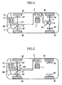
- FIG. 1 is a schematic diagram of a drive hybrid vehicle to which the present invention is applied.
- the hybrid vehicle shown in FIG. 1 is a four-wheel drive vehicle that includes an engine E and a motor M2 in the front side of the vehicle, and a motor M1 that is connected to the an input of the differential gear D in the rear side.
- the motor M1 in the rear side primarily functions as a traction motor
- the motor M2 in the front side primarily functions as a generator. Accordingly, these motors are refereed to as the traction motor M1 and the generator motor M2 where appropriate.
- the motor M2 is positioned between the engine E and a transmission T having a clutch for the transmission. Furthermore, the clutch for the transmission (not shown) is provided that mechanically connects or disconnect the driving force output from the engine E or the motor M2 at the motor side end in the transmission T.
- An electric oil pump 22 is provided to supply working pressure to the clutch for the transmission. This electric oil pump 22 is powered by electric power provided from a battery 7.
- a starting clutch C that mechanically disconnects or connects the driving force output from the motor M1 is provided between the motor M1 and the differential gear D.
- the output of the engine E and the motor M2 in the front side is transmitted to the front wheels Wf via the transmission T whereas the output of the motor M1 in the rear side is transmitted to the rear wheels Wr via the clutch C and the differential gear D.
- the motor M1 is controlled by a power drive unit (PDU) 2 in response to a control command from a motor ECU (TrMOT-ECU) 40 (see FIG. 3 ) as a motor control device.
- the motor M2 is controlled by a power drive unit (PDU) 2 in response to a control command from a MOTOR ECU (MOT/GEN-ECU) 41 (see FIG. 3 ).
- PDU power drive unit
- MOTOR ECU MOT/GEN-ECU
- a high-voltage nickel hydrogen battery (storage battery) 7 is connected to the power drive unit 2 for sending or receiving electrical power to and from the motor M1 or the motor M2.
- An auxiliary battery (not shown) is connected to the battery 7 via a downverter that is a DC-DC converter, for driving various auxiliary devices.
- the front wheels Wf that are driven by the engine E and the motor M2 have a front wheel brake Bf, and the rear wheels Wr driven by the motor M1 have a rear wheel brake Br.
- the engine E is a so-called an inline four-cylinder engine, and an electronic control throttle 12 controlled by an engine ECU (FI-ECU) 42 is provided to an intake pipe 13 of the engine E.
- the engine E in this embodiment is an engine E that is capable of supporting a deactivation operation in which an intake valve and an exhaust valve are closeable.
- an accelerator position sensor for detecting how much a accelerator pedal (AP) (not shown) is depressed is connected to the engine ECU 42.
- the engine ECU 42 calculates the amount of fuel injection from the depressed degree of the accelerator pedal or the like, and outputs a control signal dictating the amount of fuel injection to the electronic control throttle 12.
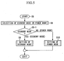
- FIG. 2 is a schematic diagram of another hybrid vehicle to which the present invention is applied.
- the hybrid vehicle shown in FIG. 2 is different from the hybrid vehicle shown in FIG. 1 in that it is a two-wheel drive vehicle and includes a traction motor M3 and a generator motor M2 in the front side of the vehicle.
- the traction motor M3 is configured such that an output shaft 10 can be connected or disconnected by means of a clutch for the transmission (not shown).
- the hybrid vehicles shown in FIGS. 1 and 2 have two drive modes: an electric vehicle (EV) drive mode in which the vehicle can be driven only by the traction motor M1/M3, and an engine drive mode in which the vehicle is driven by at least the engine E.
- the hybrid vehicles support two modes in the EV drive mode: an engine stop EV drive mode in which the vehicle is driven by the driving force output from the traction motor M1/M3 while stopping the engine E in a state in which cylinders are deactivated; and an idle cylinder deactivation EV drive mode in which the vehicle is driven by driving force output from the traction motor M1/M3 by operating the generator motor M2 as an electric motor and maintaining the engine in the deactivation state while making the engine run in a predetermined number of revaluations (for example, the engine is made to run in the idle state).
- a predetermined number of revaluations for example, the engine is made to run in the idle state.
- FIG. 3 is a block diagram of the ECU included in the hybrid vehicles shown in FIG. 1 .
- this hybrid vehicle includes a management ECU 30 that performs the overall control on the vehicle, the traction motor ECU (TrMOT-ECU) 40 that controls the traction motor M1 for driving the wheels, the generator motor ECU (MOT/GEN-ECU) 41 that controls the generator motor M2, an FI-ECU 42 that controls the engine E, and an AT-ECU 50 that controls the starting clutch C and the transmission T.
- the traction motor ECU TrMOT-ECU
- the generator motor ECU MOT/GEN-ECU 41 that controls the generator motor M2
- FI-ECU 42 that controls the engine E
- AT-ECU 50 that controls the starting clutch C and the transmission T.
- a vehicle status determination device 31 first determines the status of the vehicle based on information, such as signals from various sensors indicating the degree of depression of the accelerator pedal, the remaining capacity of the battery 7, or the like. Then, a four-wheel target driving force setting device 32 sets a target driving force required for the vehicle based on the determined status of the vehicle, and a drive mode selection device 33 selects one of the drive modes for the vehicle (e.g., from the engine stop EV drive mode, the idle cylinder deactivation EV drive mode, the engine drive mode, or the like).
- a front-rear driving force allocation setting device 34 allocates the driving force for each of the front wheels Wf and the rear wheels Wr. This allocation is varied depending on the drive mode.
- control is performed in the following manner.
- an axle shaft motor drive regeneration control device 35 controls the traction motor M1 by sending a TrMOT torque command from the axle shaft motor drive regeneration control device 35 to the TrMOT-ECU 40.
- a crank shaft motor drive regeneration control device 37 controls the generator motor M2 by sending a MOT/GEN torque command to the MOT/GEN-ECU 41.
- an engine drive control device 38 controls the engine E by sending an engine torque command to the FI-ECU 42.
- the engine may be controlled to be run at the idle speed while maintaining the deactivation operation where necessary.
- a motor clutch control device 39 sends an ON/OFF control signal to the clutch C.
- the AT-ECU 50 includes a shift control device 51.
- This shift control device 51 is connected to a drive mode selection device 33 of the management ECU such that a flag indicating the engine stop EV drive mode or the idle cylinder deactivation EV drive mode and the shift stage are communicated each other.
- an electric oil pump drive control device 61 for controlling the electric oil pump 22 is also provided.
- a transmission clutch control device 53 for controlling the transmission clutch of the transmission T is provided.
- FIG. 4 is a flowchart of a main control executed in the hybrid vehicles shown in FIG. 1 .
- a main control is started as shown in step S1
- This straight ahead/turning determination is made based on the wheel speed of the four wheels, output values from a steering angle sensor, a yaw rate sensor, and a front-rear gravity sensor.
- a straight ahead status flag is set.
- a turning status flag is set and the turning radius of the vehicle is output.
- step S3 the vehicle body speed is estimated. This estimation of the vehicle body speed is made from the wheel speed of the four wheels, the number of rotations of the transmission gears, the number of rotations of the axle shaft drive motor, and the front-rear acceleration of the vehicle.
- step S4 the target vehicle driving force is set.
- This target vehicle driving force is determined from the vehicle body speed that has been determined in step S3, the degree of the opening of the accelerator pedal, the brake switch, and the brake oil pressure (see FIG. 8 , for example).
- step S5 the drive mode is selected. This processing for selecting the drive mode will be described in detail with reference to FIG. 5 .
- the driving force allocation ratio is set. Upon determining this driving force allocation ratio, the front-rear driving force allocation ratio/engine driving force and the crank shaft motor driving force allocation ratio are determined for each of the power mode and the economy mode.
- step S7 command values are output to each of the ECUs. More specifically, the target torque/the number of rotations of the axle shaft motor, the target torque/the number of rotations of the crank shaft motor, and the target degree of opening of the throttle are output as command values to ECUs 41, 40, and 42, respectively. Then, the processing of this flowchart is terminated.
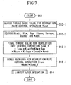
- FIG. 5 is a flowchart of the drive mode selection control executed by the hybrid vehicle shown in FIG. 1 .
- a mode selection processing from the economy mode and the power mode is executed in step S8.
- This selection of mode is made based on various types of information, such as an output from the economy mode/power mode selection switch (not shown), the status of the vehicle (whether the vehicle is slipping, turning, accelerating or decelerating), the weather, or the like.
- step S5-1 it is determined whether or not the mode selected in step S8 is the economy mode.
- the determination is evaluated as YES (the selected mode is the economy mode)
- the flow proceeds to step S9. Otherwise, when the determination is evaluated as NO (the selected mode is the power mode), the flow moves to step S 10.
- step S9 settings of the economy mode (i.e., the drive mode with two-wheel drive) are made. This processing will be described in detail later with reference to FIG. 6 .
- step S10 settings of the power mode (i.e., the drive mode with four-wheel drive) are made.
- the drive mode while the four-wheel drive mode is selected based on various types of information, such as the vehicle speed, the speed of the four wheels of the vehicle, the steering angle, the degree of the opening of the accelerator pedal, the battery charge status, or the like.
- step S9 or step S10 the processing of this flowchart is terminated, and the steps following step S6 are executed.
- FIG. 6 is a flowchart of the economy mode setting control executed in the hybrid vehicles shown in FIG. 1 .
- step S9-1 when the economy mode setting control is started in step S9, it is determined in step S9-1 whether or not the current vehicle speed exceeds the forced EV vehicle speed based on the information on the vehicle body speed that has been determined in step S3.
- this termination is evaluated as YES, the flow proceeds to step S9-2. Otherwise, when the determination is evaluated as NO, the flow moves to step S9-7.
- step S9-7 an EV drive command is output, and then the flow proceeds to step S9-11.
- step S9-2 it is determined whether or not at least one of the following conditions hold true: the current vehicle speed is equal to or less than the idle cylinder deactivation EV drive maximum vehicle speed based on the information on the vehicle body speed that has been determined in step S3, and the absolute value of the target driving force of the four wheels that has been determined in step S4 is equal to or less than the driving force calculated from the absolute value of the maximum torque of the axle shaft drive motor.
- this termination is evaluated as YES
- the flow proceeds to step S11. Otherwise, when the determination is evaluated as NO, the flow moves to step S9-10.
- step S11 the battery output available electric power (Pbatt) and the electric power (Pload) required only for performing the EV drive (the engine stop EV drive/the idle cylinder deactivation EV drive) by the axle shaft drive motor.
- the battery output available electric power (Pbatt) is calculated from the value of the battery temperature and the battery charge status information.
- the electric power only required for driving the vehicle (Pload) can be obtained by determining the foot axis output required for the four wheel drive from the target four wheel driving force that has been determined in step S4 and the vehicle speed, and performing division using the mechanical/electric efficiency of the axle shaft motor. It should be noted that the calculation of the electric power only required for driving the vehicle (Pload) can alternatively be performed using the value of the battery terminal electric power sensor during the engine stop EV drive/the idle cylinder deactivation EV drive.
- step S9-3 the allowance output (Pres) is calculated using the battery output available electric power (Pbatt) and the required electric power required for an EV drive (Pload) that have been determined in step S 11, and the electric power required for the revolution rate control operation (Prev) that has been determined in step S13. Then, in step S9-4, the threshold output (Pthre) is searched based on the current vehicle speed (see FIG. 9 ).
- step S9-5 the allowance output (Pres) that has been determined in step S9-3 is compared against the threshold output (Pthre) that has been determined in step S9-4 to determine whether or not the threshold output (Pthre) is greater than the allowance output (Pres).
- this determination is evaluated as YES (i.e., when Pthre is greater than Pres)
- the flow proceeds to step S9-6. Otherwise, the flow moves to step S9-9 when the determination is evaluated as NO (i.e., when Pthre is not greater than Pres).
- step S9-6 it is determined whether or not the current drive mode is the EV drive mode and the current vehicle speed exceeds the engine drive switching vehicle speed.
- the flow proceeds to step S9-10 when the determination is evaluated as YES; otherwise, the flow moves to step S9-8.
- step S9-10 a command requesting a transition to engine drive mode is output, and the flow then proceeds to step S9-11.
- step S9-8 a command requesting a transition to the next mode is output. That is, a command requesting a transition to the idle cylinder deactivation EV drive mode is output when the current mode is the engine stop EV drive mode. Alternatively, a command requesting a transition to engine drive mode is output when the current mode is the engine stop idle cylinder deactivation EV drive mode.
- step S9-9 a command requesting to maintain the current mode is output. Then, after executing the processing in step S9-8 or S9-9, the flow proceeds to step S9-11.
- step S9-11 it is determined whether or not a mode transition command has been issued. When this determination is evaluated as YES, the flow proceeds to step S12. Otherwise, the processing of this flowchart is terminated without executing additional steps when the determination is evaluated as NO.
- step S12 the mode transition control is executed. More specifically, in order to transition between drive modes, a limiting/filtering processing is executed for each of the torque and the number of rotations of the axle shaft drive motor M1, the torque and the number of revolutions of the engine E, and the torque and the number of rotations of the crank shaft driving motor M2, and command values for the mode transition are output to the engine E and the motor M1 and M2. Then, the processing of this flowchart is terminated.
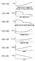
- FIG. 7 is a flowchart of an electric power calculation control for a revolution rate control operation executed in the hybrid vehicles shown in FIG. 1 .
- a torque base value for the revolution rate control operation (Tcmd) is searched based on the current drive mode and the next drive mode in step S13-1.
- a search table used upon searching the torque base value for the revolution rate control operation for switching from the current drive mode to the next drive mode is shown in Table 1.
- Table 1 Tcmd (the torque base value for the revolution rate control operation) Search Table Current Drive Mode Next Drive Mode Tcmd Engine Stop EV Idle Cylinder Deactivation EV Tcmd12 ENG drive Tcmd13 Idle Cylinder Deactivation EV Engine Stop EV Tcmd21 ENG drive Tcmd23 ENG drive Engine Stop EV Tcmd31 Idle Cylinder Deactivation EV Tcmd32
- step S13-2 coefficients for the revolution rate control operation of each parameter for the torque base value for the revolution rate control operation are searched (see FIGS. 10A to 10G ). More specifically, using the map shown in FIG. 10A , a coefficient for the revolution rate control operation for the rate of the change in the degree of the opening of the accelerator pedal (Kap) is searched from the rate of the change in the degree of the opening of the accelerator pedal. Furthermore, using the map shown in FIG 10B , a coefficient for the revolution rate control operation for the ATF temperature, i.e., the oil temperature of the transmission (Ktatf), is searched from the ATF temperature.
- Kap the rate of the change in the degree of the opening of the accelerator pedal
- Ktatf oil temperature of the transmission
- a coefficient for the revolution rate control operation for the temperature of the engine cooling water (Ktw) is searched from the temperature of the engine cooling water.
- a coefficient for the revolution rate control operation (Kturn) for the turning radius is searched from the turning radius of the vehicle.
- a coefficient for the revolution rate control operation for the slope of the road (Kslope) is searched from the slope of the road.
- a coefficient for the revolution rate control operation for the target number of revolutions of the engine Kncmd
- a coefficient for the revolution rate control operation for the battery charge status (Ksoc) is searched from the battery charge status.
- step S13-3 the torque base value for the revolution rate control operation that is determined using the above-described Table 1 is multiplied by each of the coefficients that have been determined in step S 13-2 to determine a final torque value for the revolution rate control operation (Tcmd_f). Then, in step S13-4, the final torque value for the revolution rate control operation obtained in step S13-3 is multiplied by the target number of rotations for the revolution rate control operation to determine an electric power required for the revolution rate control operation (Prev). Then, in step S14, the limiting/filtering processing is executed.
- the filtering and limiting operation is executed to prevent the calculated value of the electric power for the revolution rate control operation that has been determined in step S 13-4 from being significantly varied in the calculation, or being too great or too small. Then, the processing of this flowchart is terminated.
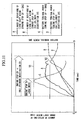
- FIG. 11 is a graph illustrating the change in the number of rotations of the crank shaft motor and the battery terminal electric power over time during a mode transition.
- the battery 7 when the mode transitions from the engine stop EV drive mode to the engine drive mode, since the number of revolutions of the engine E is required to be raised from zero to the drive speed, the battery 7 requires much electric power for increasing the number of rotations of the crank shaft motor M2 that drives the engine E (see Line A and Line C).
- the mode transitions from the engine stop EV drive mode to the idle cylinder deactivation EV drive mode it is suffice to run the engine by gradually raising the number of revolutions of the engine E from zero in the idle state.
- the electric power from the battery 7 that is required to increase the number of rotations of the crank shaft motor M2 that drives the engine E remains small (see Line B and Line D).
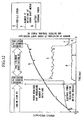
- FIG. 12 is a graph illustrating the change in the vehicle speed, the number of rotations of the crank shaft motor, and the battery terminal electric power over time during a mode transition.
- the vehicle is driven in the engine stop EV drive mode, in which the electric power output from the battery 7 (the battery terminal electric power) is approximately close to the electric power required to drive the vehicle.
- the vehicle speed is gradually increased, by transitioning to the idle cylinder deactivation EV drive mode rather than to the engine drive mode, it is not necessary to set large values for the number of rotations requested for the crank shaft motor M2 and to save the electric power required to increase the target number of rotations.
- the mode transitions to the engine drive mode.
- the electric power required to raise the number of revolutions of the engine E to the drive speed can be saved.
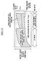
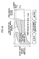
- the transition rate for driving the crank shaft motor (front motor) M2 is changed according to the drive mode to be transitioned. This will be explained with reference to FIGS. 13 to 16 .
- FIGS. 13 and 15 illustrate an example in which the transition rate (the time required to transition between modes) is changed according to the drive mode to be transitioned and the driving state of the vehicle according to this embodiment.
- FIGS. 14 and 16 illustrate a comparative example in which the transition rate remains constant regardless of the drive mode to be transitioned. As shown in the comparative example, when the transition rate remains constant, it is required to increase the number of rotations of the crank shaft motor M2 within a fixed time. Therefore, a relatively large amount of electric power for the revolution rate control operation required in the battery 7 should be reserved. As a result, even when the driver does not request an immediate acceleration request, for example, a transition of the drive mode takes place and the effect of improving the fuel consumption is limited accordingly.
- the transition rate is modified according to the drive mode to be transitioned and the driving state of the vehicle.
- This allows modification of the required electric power according to the drive mode to be transitioned, and it is possible to drive the vehicle in the current drive mode while reserving electric power suitable to each of the drive modes.
- the engine stop EV drive mode allowable region and the idle cylinder deactivation EV drive mode allowable region can be enlarged, thereby improving the fuel consumption
- the required electric power is modified according to the driving state of the vehicle, such as the acceleration intention by the driver, it is possible to further enhance the effect of improving the fuel consumption while maintaining good drivability.
- the transition rate is set to a moderate value and the electric power required for a transition of the drive mode can be saved. Accordingly, since it is possible to continue the current drive mode, the effect of improving the fuel consumption is enhanced.
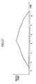
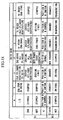
- the drive modes in this embodiment includes the idle stop mode (region a), the engine stop EV drive mode (region b), the idle cylinder deactivation EV drive mode (region c), the engine drive mode (region d), the engine drag rear regeneration mode (region e), the idle cylinder deactivation rear regeneration mode (region f), and the engine stop rear regeneration mode (region g).
- Operating statuses of the engine E, the front motor M2, the transmission T, and the clutch C and the rear motor M1 on the rear side in each mode are shown in FIG. 18 .
- FIG. 17 is a diagram illustrating an example of the change in the vehicle speed over time for each drive mode.
- the clutch C is connected only when the driving force of the motor M1 is required, whereas the motor M1 is disconnected from the driving wheels Wr when such driving force is not required (in the engine drive mode). Accordingly, it is possible to reduce the friction from the motor M1, thereby contributing to an improvement in the fuel consumption. Furthermore, the transmission clutch between the engine E and the driving wheels Wf is connected only when the driving force of the engine E is required, whereas the engine E is disconnected from the driving wheels Wf when such driving force is not required (in the engine drive mode). Accordingly, it is possible to reduce the friction from the engine E, thereby contributing to an improvement in the fuel consumption.
- the engine E is configured to be an engine E that is capable of supporting a deactivation operation in which an intake valve and an exhaust valve are closeable, and the engine E is deactivated in the idle cylinder deactivation EV drive mode. Accordingly, it is possible to reduce the pumping loss involved in the open/close of the intake valve and the exhaust valve, in addition to stopping the fuel injection.
- the vehicle supports the idle cylinder deactivation EV drive mode in which the engine is maintained in the deactivation state while made to run in a predetermined number of revaluations (for example, the engine is made to run in the idle state), in addition to the engine stop EV drive mode and the idle cylinder deactivation EV drive mode. Accordingly, it is possible to transition to the engine drive mode by promptly driving the engine E, and the electric power required for the revolution rate control operation for raising the number of revolutions of the engine E can be reduced. Additionally, the electric power required for the revolution rate control operation for driving the engine E can be reduced when the mode transitions from the engine stop EV drive mode to the idle cylinder deactivation EV drive mode.
Landscapes
- Engineering & Computer Science (AREA)
- Combustion & Propulsion (AREA)
- Chemical & Material Sciences (AREA)
- Mechanical Engineering (AREA)
- Transportation (AREA)
- Automation & Control Theory (AREA)
- Human Computer Interaction (AREA)
- Output Control And Ontrol Of Special Type Engine (AREA)
- Hybrid Electric Vehicles (AREA)
- Arrangement And Driving Of Transmission Devices (AREA)
- Control Of Vehicle Engines Or Engines For Specific Uses (AREA)
- Electric Propulsion And Braking For Vehicles (AREA)
- Arrangement Of Transmissions (AREA)
Claims (9)
- Steuervorrichtung für ein Hybridfahrzeug, umfassend:Brennkraftmaschine (E) als erste Antriebsquelle zum Antreiben des Fahrzeugs, wobei die Brennkraftmaschine (E) konfiguriert ist, um einen Deaktivierungsbetrieb, in dem ein Einlassventil und ein Auslassventil geschlossen sind, zu unterstützen;einen Elektromotor (M1, M3) als zweite Antriebsquelle zum Antreiben des Fahrzeugs;einen Stromgenerator (M2), der von der Brennkraftmaschine (E) angetrieben wird; undeine elektrische Speichervorrichtung (7) zum Speichern von Regenerationsenergie von dem Stromgenerator (M2) und dem Elektromotor (M1; M3),wobei die Steuervorrichtung umfasst:eine Antriebsmodusbestimmungsvorrichtung, die aus einer Mehrzahl von Antriebsmodi basierend auf einem Zustand des Fahrzeugs einen Antriebsmodus bestimmt, wobei die Antriebsmodi umfassen:einen Maschinenstopp-Motorantriebsmodus, in dem das Fahrzeug durch Antriebskraft von dem Elektromotor (M1; M3) angetrieben wird, während die Brennkraftmaschine (E) gestoppt ist;einen Leerlaufzylinderdeaktivierungs-Motorantriebsmodus, in dem das Fahrzeug durch die Antriebskraft von dem Elektromotor (M1; M3) angetrieben wird, indem durch Laufenlassen der Brennkraftmaschine (E), während die Brennkraftmaschine (E) deaktiviert bleibt, der Stromgenerator (M2) als Elektromotor betätigt wird; undeinen Maschinenantriebsmodus, in dem das Fahrzeug durch Antriebskraft von der Brennkraftmaschine (E) angetrieben wird;eine Übergangsratenmodifikationsvorrichtung, die dann, wenn durch die Antriebsmodusbestimmungsvorrichtung bestimmt wird, dass ein Modusübergang von einem gegenwärtigen Antriebsmodus zu einem anderen Antriebsmodus stattfinden soll, eine Übergangsrate zum Überleiten vom gegenwärtigen Antriebsmodus zum anderen Antriebsmodus gemäß dem überzuleitenden Antriebsmodus modifiziert, undeine Stromenergiesetzvorrichtung, die eine elektrische Energie setzt, die zum Antrieb des Stromgenerators (M22) als Elektromotor verwendet wird, basierend auf der in der Übergangsratenmodifikationsvorrichtung modifizierten Übergangsrate,dadurch gekennzeichnet, dass die Stromenergiesetzvorrichtung die elektrische Energie basierend auf einer Änderungsrate im Öffnungsgrad eines Gaspedals setzt.
- Steuervorrichtung für ein Hybridfahrzeug nach Anspruch 1, worin die Stromenergiesetzvorrichtung die elektrische Energie basierend auf einer Öltemperatur eines Getriebes (T) und einer Öltemperatur der Brennkraftmaschine (E) setzt.
- Steuervorrichtung für ein Hybridfahrzeug nach Anspruch 1, worin die Stromenergiesetzvorrichtung die elektrische Energie basierend auf einem Ladezustand der elektrischen Speichervorrichtung (7) setzt.
- Steuervorrichtung für ein Hybridfahrzeug nach Anspruch 1, worin die Stromenergiesetzvorrichtung die elektrische Energie basierend auf einer Sollübergangsrate setzt.
- Steuervorrichtung für ein Hybridfahrzeug nach Anspruch 1, die ferner eine Geradeaus- oder Kurvenfahrtbestimmungsvorrichtung aufweist, die bestimmt, ob das Fahrzeug geradeaus oder eine Kurve fährt,
worin eine Solldrehzahl der Brennkraftmaschine (E) entsprechend einem von der Geradeaus- oder Kurvenfahrtbestimmungsvorrichtung bestimmten Fahrzustand geändert wird. - Steuervorrichtung für ein Hybridfahrzeug nach Anspruch 1, die ferner eine Straßenzustandbestimmungsvorrichtung aufweist, die bestimmt, ob eine Straße, auf der das Fahrzeug fährt, eine flache Straße oder eine ansteigende Straße ist,
worin eine Solldrehzahl der Brennkraftmaschine (E) entsprechend einem von der Straßenzustandbestimmungsvorrichtung bestimmten Straßenzustand geändert wird. - Steuervorrichtung für ein Hybridfahrzeug nach Anspruch 1, wobei ein Paar der Hinterräder und der Vorderräder durch die Brennkraftmaschine (E) angetrieben wird und das andere Paar durch den Elektromotor (M1, M3) angetrieben wird.
- Steuervorrichtung für ein Hybridfahrzeug nach Anspruch 1, worin zwischen den Elektromotor (M1) und die Antriebsräder eine Kupplung (C) eingefügt ist.
- Steuervorrichtung für ein Hybridfahrzeug nach Anspruch 1, worin zwischen die Brennkraftmaschine (E) und die Antriebsräder eine Kupplung eingefügt ist.
Applications Claiming Priority (1)
| Application Number | Priority Date | Filing Date | Title |
|---|---|---|---|
| JP2004256859A JP4005069B2 (ja) | 2004-09-03 | 2004-09-03 | ハイブリッド車両の制御装置 |
Publications (3)
| Publication Number | Publication Date |
|---|---|
| EP1632378A2 EP1632378A2 (de) | 2006-03-08 |
| EP1632378A3 EP1632378A3 (de) | 2006-12-20 |
| EP1632378B1 true EP1632378B1 (de) | 2008-10-08 |
Family
ID=35033352
Family Applications (1)
| Application Number | Title | Priority Date | Filing Date |
|---|---|---|---|
| EP05018852A Ceased EP1632378B1 (de) | 2004-09-03 | 2005-08-30 | Steuervorrichtung für Hybridfahrzeug |
Country Status (4)
| Country | Link |
|---|---|
| US (1) | US7540344B2 (de) |
| EP (1) | EP1632378B1 (de) |
| JP (1) | JP4005069B2 (de) |
| DE (1) | DE602005010170D1 (de) |
Families Citing this family (69)
| Publication number | Priority date | Publication date | Assignee | Title |
|---|---|---|---|---|
| JP4265592B2 (ja) * | 2005-10-05 | 2009-05-20 | トヨタ自動車株式会社 | 車両の減速制御装置 |
| WO2007060853A1 (ja) * | 2005-11-24 | 2007-05-31 | Toyota Jidosha Kabushiki Kaisha | ハイブリッド車両 |
| US8352150B2 (en) | 2006-04-07 | 2013-01-08 | Fuji Jukogyo Kabushiki Kaisha | Engine control apparatus |
| JP4072921B2 (ja) | 2006-04-07 | 2008-04-09 | 富士重工業株式会社 | 車両用表示装置 |
| DE102007016621B4 (de) | 2006-04-07 | 2012-02-02 | Fuji Jukogyo K.K. | Antriebskraft-Steuereinheit für ein Fahrzeug |
| JP2007314052A (ja) * | 2006-05-26 | 2007-12-06 | Nikkari Co Ltd | ハイブリッド式軌条運搬車 |
| US8620498B2 (en) * | 2006-06-20 | 2013-12-31 | GM Global Technology Operations LLC | Hybrid road grade determination system |
| JP4321569B2 (ja) * | 2006-09-05 | 2009-08-26 | 日産自動車株式会社 | 車両の制御装置及び制御方法 |
| FR2907380B1 (fr) * | 2006-10-20 | 2009-06-05 | Peugeot Citroen Automobiles Sa | Vehicule hybride et son procede de pilotage. |
| JP4817187B2 (ja) * | 2006-11-29 | 2011-11-16 | ヤマハ発動機株式会社 | エンジンのバルブタイミング制御装置 |
| JP2007278273A (ja) * | 2006-12-27 | 2007-10-25 | Fuji Heavy Ind Ltd | 車両のエンジン制御装置 |
| JP4201044B2 (ja) | 2007-01-09 | 2008-12-24 | トヨタ自動車株式会社 | 車両およびその制御方法 |
| JP4229185B2 (ja) | 2007-01-12 | 2009-02-25 | トヨタ自動車株式会社 | ハイブリッド自動車およびその制御方法 |
| JP4997986B2 (ja) * | 2007-01-19 | 2012-08-15 | トヨタ自動車株式会社 | ハイブリッド車両の制御装置 |
| DE102007023164A1 (de) | 2007-05-16 | 2008-11-20 | Robert Bosch Gmbh | Verfahren zum Betreiben eines Hybridantriebs eines Fahrzeugs |
| DE102007025954A1 (de) * | 2007-06-04 | 2008-12-11 | Robert Bosch Gmbh | Elektromaschinensystem |
| DE102007031605A1 (de) * | 2007-07-06 | 2009-01-22 | Dr. Ing. H.C. F. Porsche Aktiengesellschaft | Hybridfahrzeug |
| DE102007043605A1 (de) | 2007-09-13 | 2009-03-19 | Robert Bosch Gmbh | Verfahren zur dynamischen Moment- und/oder Drehzahlkoordination von Antriebsaggregaten eines Hybridantriebs und entsprechende Vorrichtung |
| JP4329856B2 (ja) * | 2007-10-16 | 2009-09-09 | トヨタ自動車株式会社 | 車両の駆動制御装置 |
| US8155814B2 (en) * | 2007-11-03 | 2012-04-10 | GM Global Technology Operations LLC | Method of operating a vehicle utilizing regenerative braking |
| US8112206B2 (en) * | 2007-11-04 | 2012-02-07 | GM Global Technology Operations LLC | Method for controlling a powertrain system based upon energy storage device temperature |
| JP2009126450A (ja) * | 2007-11-27 | 2009-06-11 | Toyota Motor Corp | ハイブリッド車及びハイブリッド車の制御方法 |
| US8596390B2 (en) * | 2007-12-05 | 2013-12-03 | Ford Global Technologies, Llc | Torque control for hybrid electric vehicle speed control operation |
| FR2928122B1 (fr) * | 2008-03-03 | 2010-05-21 | Renault Sas | Systeme de commande d'un groupe motopropulseur hybride pour vehicule automobile, et procede associe |
| JPWO2010052768A1 (ja) * | 2008-11-05 | 2012-03-29 | トヨタ自動車株式会社 | ハイブリッド車両の制御装置 |
| DE102008043849A1 (de) * | 2008-11-19 | 2010-05-20 | Zf Friedrichshafen Ag | Mehrachsiges Hybrid-Antriebssystem für ein Fahrzeug |
| US20110231049A1 (en) * | 2008-12-08 | 2011-09-22 | Renault Trucks | Method for controlling operation of a hybrid automotive and vehicle adapted to such a method |
| US20100161199A1 (en) * | 2008-12-22 | 2010-06-24 | Gauthier Eric | Fuel consumption saving system and a method of operation thereof |
| US8326519B2 (en) * | 2009-02-25 | 2012-12-04 | GM Global Technology Operations LLC | Oxygen flow reduction during engine start/stop operation |
| US8083016B2 (en) * | 2009-04-13 | 2011-12-27 | GM Global Technology Operations LLC | Vehicle with hybrid powertrain |
| JP4962623B2 (ja) * | 2009-05-21 | 2012-06-27 | トヨタ自動車株式会社 | エンジントルク推定装置 |
| SE535739C2 (sv) * | 2009-06-10 | 2012-11-27 | Scania Cv Ab | Metod och system för att styra en elmaskin i ett hybridfordon |
| US8855840B2 (en) * | 2010-02-03 | 2014-10-07 | Toyota Motor Engineering & Manufacturing North America, Inc. | Method and system for more efficient operation of plug-in electric vehicles |
| US8433465B2 (en) * | 2010-06-08 | 2013-04-30 | Ford Global Technologies, Llc | Transitioning between series-drive and parallel-drive in a hybrid-electric vehicle powertrain |
| CN102939214B (zh) | 2010-06-15 | 2015-08-19 | 本田技研工业株式会社 | 混合动力车辆用驱动装置 |
| DE102010033431A1 (de) * | 2010-08-04 | 2012-02-09 | Mattias Vesterlund | Kraftfahrzeug und Verfahren zum Antreiben eines Kraftfahrzeugs |
| CN102770644B (zh) * | 2010-12-24 | 2013-10-23 | 株式会社小松制作所 | 轮式装载机 |
| US20140116793A1 (en) * | 2011-06-09 | 2014-05-01 | Prevost, Une Division De Groupe Volvo Canada Inc. | Hybrid vehicle |
| JP5742607B2 (ja) * | 2011-09-08 | 2015-07-01 | 三菱自動車工業株式会社 | ハイブリッド電気自動車の制御装置 |
| US8781713B2 (en) * | 2011-09-23 | 2014-07-15 | GM Global Technology Operations LLC | System and method for controlling a valve of a cylinder in an engine based on fuel delivery to the cylinder |
| JP6100690B2 (ja) * | 2011-09-27 | 2017-03-22 | トヨタ自動車株式会社 | 車両 |
| JP5811181B2 (ja) | 2011-09-27 | 2015-11-11 | トヨタ自動車株式会社 | 車両および車両の制御方法 |
| WO2013046312A1 (ja) * | 2011-09-27 | 2013-04-04 | トヨタ自動車株式会社 | 車両および車両の制御方法 |
| US9239017B2 (en) | 2011-11-01 | 2016-01-19 | GM Global Technology Operations LLC | Stop-start control systems for engines with fully flexible valve actuation system |
| JP2013107412A (ja) * | 2011-11-17 | 2013-06-06 | Gkn Driveline Japan Ltd | 四輪駆動車 |
| CN103158695B (zh) * | 2011-12-16 | 2016-01-13 | 北汽福田汽车股份有限公司 | 混合动力汽车动力分配的控制方法 |
| US9580062B2 (en) * | 2012-01-10 | 2017-02-28 | Ford Global Technologies, Llc | Method for increasing fuel economy of plug-in hybrid electric vehicles |
| WO2013137080A1 (ja) * | 2012-03-13 | 2013-09-19 | 日産自動車株式会社 | ハイブリッド車両の制御装置 |
| SE1350152A1 (sv) * | 2013-02-08 | 2014-08-09 | BAE Systems Hägglunds Aktiebolag | Förfarande och system för styrning av ett fordons drivlina |
| FR3004231B1 (fr) * | 2013-04-05 | 2015-04-03 | Renault Sa | Procede de controle de l'etat d'une chaine cinematique d'un groupe motopropulseur de vehicule electrique hybride ou thermique |
| JP6155917B2 (ja) * | 2013-07-11 | 2017-07-05 | トヨタ自動車株式会社 | ハイブリッド車両の制御装置 |
| JP5642253B1 (ja) * | 2013-11-08 | 2014-12-17 | 三菱電機株式会社 | 車両用エネルギーマネジメント装置 |
| KR101575532B1 (ko) * | 2014-09-23 | 2015-12-22 | 현대자동차주식회사 | 하이브리드 차량의 파워트레인 |
| JP6374803B2 (ja) * | 2015-02-24 | 2018-08-15 | 株式会社Subaru | ハイブリッド車 |
| US20150225006A1 (en) * | 2015-02-27 | 2015-08-13 | Frank William THIEL | Multifunctional Utility Cart |
| US10807659B2 (en) | 2016-05-27 | 2020-10-20 | Joseph L. Pikulski | Motorized platforms |
| US10071303B2 (en) | 2015-08-26 | 2018-09-11 | Malibu Innovations, LLC | Mobilized cooler device with fork hanger assembly |
| US9687080B1 (en) | 2016-04-29 | 2017-06-27 | Frank W. Thiel | Adjustable stool |
| FR3070151B1 (fr) * | 2017-08-18 | 2020-10-23 | Psa Automobiles Sa | Procede de commutation entre modes de transmission sur un vehicule automobile hybride |
| CN111971196B (zh) * | 2018-04-13 | 2024-03-26 | 德纳重型车辆系统集团有限责任公司 | 用于单模式和多模式电动副桥或电动支持桥的控制策略 |
| DE102019107772A1 (de) * | 2018-12-04 | 2020-06-04 | Bayerische Motoren Werke Aktiengesellschaft | Steuereinheit und Verfahren zum Betrieb eines Hybridantriebs |
| KR102659247B1 (ko) | 2019-07-15 | 2024-04-18 | 현대자동차주식회사 | 하이브리드 차량의 펌핑로스 저감 시스템 및 방법 |
| JP2021138309A (ja) * | 2020-03-06 | 2021-09-16 | 本田技研工業株式会社 | 車両 |
| US11597374B2 (en) * | 2020-09-10 | 2023-03-07 | Ford Global Technologies, Llc | Methods and system for arbitrating fuel cut out for a hybrid vehicle |
| JP7410913B2 (ja) | 2021-09-30 | 2024-01-10 | 本田技研工業株式会社 | 車両 |
| US12233881B2 (en) * | 2022-02-07 | 2025-02-25 | Ford Global Technologies, Llc | Methods and systems for vehicle operation based on the determined driver category |
| JP7704083B2 (ja) * | 2022-06-29 | 2025-07-08 | トヨタ自動車株式会社 | ハイブリッド車両の制御装置 |
| CN116424297A (zh) * | 2023-04-21 | 2023-07-14 | 蜂巢传动系统(江苏)有限公司 | 混动车辆的模式切换控制方法、装置、存储介质和车辆 |
| CN117141457A (zh) * | 2023-06-21 | 2023-12-01 | 长城汽车股份有限公司 | 车辆控制方法、装置、存储介质及电子设备 |
Family Cites Families (18)
| Publication number | Priority date | Publication date | Assignee | Title |
|---|---|---|---|---|
| US5408974A (en) * | 1993-12-23 | 1995-04-25 | Ford Motor Company | Cylinder mode selection system for variable displacement internal combustion engine |
| JP3534271B2 (ja) * | 1995-04-20 | 2004-06-07 | 株式会社エクォス・リサーチ | ハイブリッド車両 |
| JPH08318765A (ja) * | 1995-05-25 | 1996-12-03 | Hitachi Ltd | 情報化自動車制御装置及び方法 |
| JP3099723B2 (ja) | 1996-02-19 | 2000-10-16 | トヨタ自動車株式会社 | 車輌のエンジン制御装置およびその制御方法 |
| JP3500882B2 (ja) | 1996-11-18 | 2004-02-23 | トヨタ自動車株式会社 | ブレーキ液圧制御装置 |
| US6885920B2 (en) * | 1999-07-30 | 2005-04-26 | Oshkosh Truck Corporation | Control system and method for electric vehicle |
| JP2001260836A (ja) * | 2000-03-23 | 2001-09-26 | Toyota Motor Corp | 車両用駆動力配分制御装置 |
| JP4070401B2 (ja) | 2000-10-31 | 2008-04-02 | 日産ディーゼル工業株式会社 | 車両のハイブリッドシステム |
| US6499449B2 (en) * | 2001-01-25 | 2002-12-31 | Ford Global Technologies, Inc. | Method and system for operating variable displacement internal combustion engine |
| JP4092886B2 (ja) | 2001-03-30 | 2008-05-28 | アイシン・エィ・ダブリュ株式会社 | 電動車両用駆動制御装置、電動車両用駆動制御方法及びプログラム |
| US20020179348A1 (en) * | 2001-05-30 | 2002-12-05 | Goro Tamai | Apparatus and method for controlling a hybrid vehicle |
| US6829524B2 (en) * | 2001-08-20 | 2004-12-07 | Wisys Technology Foundation, Inc. | Method and apparatus for estimating yaw rate in a wheeled vehicle and stability system |
| US6638195B2 (en) * | 2002-02-27 | 2003-10-28 | New Venture Gear, Inc. | Hybrid vehicle system |
| JP3700974B2 (ja) | 2002-11-18 | 2005-09-28 | 本田技研工業株式会社 | エンジン制御装置 |
| JP3771213B2 (ja) * | 2002-11-19 | 2006-04-26 | 本田技研工業株式会社 | ハイブリッド車両のクラッチ制御装置 |
| JP3817516B2 (ja) * | 2002-12-26 | 2006-09-06 | 本田技研工業株式会社 | ハイブリッド車両の駆動制御装置 |
| JP4200762B2 (ja) | 2003-01-06 | 2008-12-24 | 日産自動車株式会社 | 4輪駆動車両の旋回挙動制御装置 |
| JP4224850B2 (ja) | 2003-02-25 | 2009-02-18 | 独立行政法人 日本原子力研究開発機構 | 光触媒アナターゼ型二酸化チタン薄膜の製造方法 |
-
2004
- 2004-09-03 JP JP2004256859A patent/JP4005069B2/ja not_active Expired - Fee Related
-
2005
- 2005-08-30 EP EP05018852A patent/EP1632378B1/de not_active Ceased
- 2005-08-30 DE DE602005010170T patent/DE602005010170D1/de not_active Expired - Lifetime
- 2005-09-01 US US11/215,970 patent/US7540344B2/en not_active Expired - Fee Related
Also Published As
| Publication number | Publication date |
|---|---|
| DE602005010170D1 (de) | 2008-11-20 |
| EP1632378A3 (de) | 2006-12-20 |
| JP4005069B2 (ja) | 2007-11-07 |
| EP1632378A2 (de) | 2006-03-08 |
| US7540344B2 (en) | 2009-06-02 |
| US20060048982A1 (en) | 2006-03-09 |
| JP2006074931A (ja) | 2006-03-16 |
Similar Documents
| Publication | Publication Date | Title |
|---|---|---|
| EP1632378B1 (de) | Steuervorrichtung für Hybridfahrzeug | |
| US7216729B2 (en) | Method and system of requesting engine on/off state in a hybrid electric vehicle | |
| JP3701662B2 (ja) | ハイブリッド車両の自動変速機制御装置 | |
| US6867509B1 (en) | Control apparatus for transmission-equipped hybrid vehicle, and control method for the same | |
| CN100436886C (zh) | 混合动力车辆的电动油泵控制装置 | |
| US7874956B2 (en) | Engine start controlling apparatus and method for hybrid vehicle | |
| JP3589208B2 (ja) | ハイブリッド車両の駆動装置 | |
| KR102310547B1 (ko) | 하이브리드 차량의 오토 크루즈 제어 방법 | |
| JP2009292464A (ja) | 内燃機関電気ハイブリッド車両用制御方法及び装置 | |
| KR20160063820A (ko) | 하이브리드 차량의 회생제동 제어방법 | |
| CN110615000A (zh) | 一种插电式混合动力汽车工作控制模式 | |
| KR100992721B1 (ko) | 하이브리드 차량의 토크 저감 방법 | |
| JP7283073B2 (ja) | 四輪駆動車両のトルク制御装置 | |
| CN108177649B (zh) | 一种混合动力汽车的换档方法及装置 | |
| JP3601508B2 (ja) | 有段変速機を備えたハイブリッド車両 | |
| JP2017094823A (ja) | ハイブリッド車の制動制御装置 | |
| CN113022534A (zh) | 用于管理混合动力电动车辆的电机的温度的系统和方法 | |
| JPH09224303A (ja) | ハイブリッド自動車の車両制御装置 | |
| JP4035930B2 (ja) | 電動発電機を備えた車両の制御装置 | |
| JP2002345105A (ja) | 電気自動車 | |
| JP2006170265A (ja) | 自動車およびその制御方法 | |
| JP2022178038A (ja) | 制御装置 | |
| JP2021054134A (ja) | ハイブリッド車のエンジン制御方法及びエンジン制御装置 | |
| JP2014043183A (ja) | ハイブリッド車両 | |
| WO2013137213A1 (ja) | ハイブリッド車両の制御装置 |
Legal Events
| Date | Code | Title | Description |
|---|---|---|---|
| PUAI | Public reference made under article 153(3) epc to a published international application that has entered the european phase |
Free format text: ORIGINAL CODE: 0009012 |
|
| AK | Designated contracting states |
Kind code of ref document: A2 Designated state(s): AT BE BG CH CY CZ DE DK EE ES FI FR GB GR HU IE IS IT LI LT LU LV MC NL PL PT RO SE SI SK TR |
|
| AX | Request for extension of the european patent |
Extension state: AL BA HR MK YU |
|
| PUAL | Search report despatched |
Free format text: ORIGINAL CODE: 0009013 |
|
| AK | Designated contracting states |
Kind code of ref document: A3 Designated state(s): AT BE BG CH CY CZ DE DK EE ES FI FR GB GR HU IE IS IT LI LT LU LV MC NL PL PT RO SE SI SK TR |
|
| AX | Request for extension of the european patent |
Extension state: AL BA HR MK YU |
|
| 17P | Request for examination filed |
Effective date: 20070419 |
|
| 17Q | First examination report despatched |
Effective date: 20070619 |
|
| AKX | Designation fees paid |
Designated state(s): DE GB |
|
| GRAP | Despatch of communication of intention to grant a patent |
Free format text: ORIGINAL CODE: EPIDOSNIGR1 |
|
| RIC1 | Information provided on ipc code assigned before grant |
Ipc: B60W 10/08 20060101ALI20080514BHEP Ipc: B60K 6/52 20071001AFI20080514BHEP Ipc: B60W 20/00 20060101ALI20080514BHEP Ipc: B60W 10/06 20060101ALI20080514BHEP |
|
| GRAS | Grant fee paid |
Free format text: ORIGINAL CODE: EPIDOSNIGR3 |
|
| GRAA | (expected) grant |
Free format text: ORIGINAL CODE: 0009210 |
|
| AK | Designated contracting states |
Kind code of ref document: B1 Designated state(s): DE GB |
|
| REG | Reference to a national code |
Ref country code: GB Ref legal event code: FG4D |
|
| REF | Corresponds to: |
Ref document number: 602005010170 Country of ref document: DE Date of ref document: 20081120 Kind code of ref document: P |
|
| PLBE | No opposition filed within time limit |
Free format text: ORIGINAL CODE: 0009261 |
|
| STAA | Information on the status of an ep patent application or granted ep patent |
Free format text: STATUS: NO OPPOSITION FILED WITHIN TIME LIMIT |
|
| 26N | No opposition filed |
Effective date: 20090709 |
|
| PGFP | Annual fee paid to national office [announced via postgrant information from national office to epo] |
Ref country code: GB Payment date: 20130828 Year of fee payment: 9 |
|
| REG | Reference to a national code |
Ref country code: DE Ref legal event code: R084 Ref document number: 602005010170 Country of ref document: DE Effective date: 20140430 |
|
| GBPC | Gb: european patent ceased through non-payment of renewal fee |
Effective date: 20140830 |
|
| PG25 | Lapsed in a contracting state [announced via postgrant information from national office to epo] |
Ref country code: GB Free format text: LAPSE BECAUSE OF NON-PAYMENT OF DUE FEES Effective date: 20140830 |
|
| PGFP | Annual fee paid to national office [announced via postgrant information from national office to epo] |
Ref country code: DE Payment date: 20180814 Year of fee payment: 14 |
|
| REG | Reference to a national code |
Ref country code: DE Ref legal event code: R119 Ref document number: 602005010170 Country of ref document: DE |
|
| PG25 | Lapsed in a contracting state [announced via postgrant information from national office to epo] |
Ref country code: DE Free format text: LAPSE BECAUSE OF NON-PAYMENT OF DUE FEES Effective date: 20200303 |