EP1603679B1 - Stülpfilterzentrifuge - Google Patents
Stülpfilterzentrifuge Download PDFInfo
- Publication number
- EP1603679B1 EP1603679B1 EP04717019A EP04717019A EP1603679B1 EP 1603679 B1 EP1603679 B1 EP 1603679B1 EP 04717019 A EP04717019 A EP 04717019A EP 04717019 A EP04717019 A EP 04717019A EP 1603679 B1 EP1603679 B1 EP 1603679B1
- Authority
- EP
- European Patent Office
- Prior art keywords
- inverting
- centrifugal chamber
- centrifuge according
- filter centrifuge
- filter
- Prior art date
- Legal status (The legal status is an assumption and is not a legal conclusion. Google has not performed a legal analysis and makes no representation as to the accuracy of the status listed.)
- Expired - Lifetime
Links
- 239000007787 solid Substances 0.000 claims abstract description 92
- 230000003068 static effect Effects 0.000 claims abstract description 18
- 239000004744 fabric Substances 0.000 claims abstract description 17
- 238000006073 displacement reaction Methods 0.000 claims abstract description 6
- 239000002245 particle Substances 0.000 claims abstract description 5
- 238000000034 method Methods 0.000 claims description 29
- 230000008569 process Effects 0.000 claims description 29
- 239000007788 liquid Substances 0.000 claims description 23
- 230000033001 locomotion Effects 0.000 claims description 19
- 238000005299 abrasion Methods 0.000 claims description 16
- 238000004140 cleaning Methods 0.000 claims description 6
- 230000001681 protective effect Effects 0.000 claims description 4
- 230000008030 elimination Effects 0.000 claims description 2
- 238000003379 elimination reaction Methods 0.000 claims description 2
- 230000007704 transition Effects 0.000 claims description 2
- 238000011109 contamination Methods 0.000 abstract description 12
- 238000009434 installation Methods 0.000 abstract description 8
- 230000009471 action Effects 0.000 abstract description 2
- 238000007599 discharging Methods 0.000 abstract description 2
- 239000000825 pharmaceutical preparation Substances 0.000 abstract 1
- 229940127557 pharmaceutical product Drugs 0.000 abstract 1
- 238000007789 sealing Methods 0.000 description 26
- 239000000725 suspension Substances 0.000 description 22
- 239000007789 gas Substances 0.000 description 18
- 239000000047 product Substances 0.000 description 11
- 238000005406 washing Methods 0.000 description 10
- 238000013461 design Methods 0.000 description 7
- 238000004519 manufacturing process Methods 0.000 description 7
- 238000000926 separation method Methods 0.000 description 6
- 238000013022 venting Methods 0.000 description 6
- 239000000706 filtrate Substances 0.000 description 5
- 230000000149 penetrating effect Effects 0.000 description 5
- 230000008901 benefit Effects 0.000 description 4
- 239000012065 filter cake Substances 0.000 description 4
- 230000002093 peripheral effect Effects 0.000 description 4
- 239000000443 aerosol Substances 0.000 description 3
- 230000005540 biological transmission Effects 0.000 description 3
- 230000008859 change Effects 0.000 description 3
- 238000012864 cross contamination Methods 0.000 description 3
- 238000005202 decontamination Methods 0.000 description 3
- 230000003588 decontaminative effect Effects 0.000 description 3
- 238000001914 filtration Methods 0.000 description 3
- 230000002906 microbiologic effect Effects 0.000 description 3
- 230000036961 partial effect Effects 0.000 description 3
- 238000005192 partition Methods 0.000 description 3
- 230000009467 reduction Effects 0.000 description 3
- 230000002829 reductive effect Effects 0.000 description 3
- 238000011144 upstream manufacturing Methods 0.000 description 3
- 238000005516 engineering process Methods 0.000 description 2
- 230000002349 favourable effect Effects 0.000 description 2
- 238000005429 filling process Methods 0.000 description 2
- 238000011089 mechanical engineering Methods 0.000 description 2
- 230000035515 penetration Effects 0.000 description 2
- 238000003860 storage Methods 0.000 description 2
- 238000012546 transfer Methods 0.000 description 2
- 239000013543 active substance Substances 0.000 description 1
- 230000032683 aging Effects 0.000 description 1
- 238000013459 approach Methods 0.000 description 1
- 230000000712 assembly Effects 0.000 description 1
- 238000000429 assembly Methods 0.000 description 1
- 230000004888 barrier function Effects 0.000 description 1
- 230000000711 cancerogenic effect Effects 0.000 description 1
- 231100000315 carcinogenic Toxicity 0.000 description 1
- 239000000470 constituent Substances 0.000 description 1
- 230000008878 coupling Effects 0.000 description 1
- 238000010168 coupling process Methods 0.000 description 1
- 238000005859 coupling reaction Methods 0.000 description 1
- 239000013078 crystal Substances 0.000 description 1
- 238000011161 development Methods 0.000 description 1
- 230000018109 developmental process Effects 0.000 description 1
- 238000001035 drying Methods 0.000 description 1
- 230000000694 effects Effects 0.000 description 1
- 230000007717 exclusion Effects 0.000 description 1
- 238000000605 extraction Methods 0.000 description 1
- 210000003746 feather Anatomy 0.000 description 1
- 239000010419 fine particle Substances 0.000 description 1
- 239000011521 glass Substances 0.000 description 1
- 230000006872 improvement Effects 0.000 description 1
- 239000011261 inert gas Substances 0.000 description 1
- 238000007689 inspection Methods 0.000 description 1
- 230000007774 longterm Effects 0.000 description 1
- 238000012423 maintenance Methods 0.000 description 1
- 230000001404 mediated effect Effects 0.000 description 1
- 239000012528 membrane Substances 0.000 description 1
- 230000000737 periodic effect Effects 0.000 description 1
- 238000005070 sampling Methods 0.000 description 1
- 238000005201 scrubbing Methods 0.000 description 1
- 239000000126 substance Substances 0.000 description 1
- 230000001360 synchronised effect Effects 0.000 description 1
- 238000012360 testing method Methods 0.000 description 1
- 230000036962 time dependent Effects 0.000 description 1
- 231100000331 toxic Toxicity 0.000 description 1
- 230000002588 toxic effect Effects 0.000 description 1
- 238000013519 translation Methods 0.000 description 1
- 238000003466 welding Methods 0.000 description 1
Images


Classifications
-
- B—PERFORMING OPERATIONS; TRANSPORTING
- B04—CENTRIFUGAL APPARATUS OR MACHINES FOR CARRYING-OUT PHYSICAL OR CHEMICAL PROCESSES
- B04B—CENTRIFUGES
- B04B11/00—Feeding, charging, or discharging bowls
- B04B11/06—Arrangement of distributors or collectors in centrifuges
-
- B—PERFORMING OPERATIONS; TRANSPORTING
- B04—CENTRIFUGAL APPARATUS OR MACHINES FOR CARRYING-OUT PHYSICAL OR CHEMICAL PROCESSES
- B04B—CENTRIFUGES
- B04B15/00—Other accessories for centrifuges
- B04B15/08—Other accessories for centrifuges for ventilating or producing a vacuum in the centrifuge
-
- B—PERFORMING OPERATIONS; TRANSPORTING
- B04—CENTRIFUGAL APPARATUS OR MACHINES FOR CARRYING-OUT PHYSICAL OR CHEMICAL PROCESSES
- B04B—CENTRIFUGES
- B04B3/00—Centrifuges with rotary bowls in which solid particles or bodies become separated by centrifugal force and simultaneous sifting or filtering
- B04B3/02—Centrifuges with rotary bowls in which solid particles or bodies become separated by centrifugal force and simultaneous sifting or filtering discharging solid particles from the bowl by means coaxial with the bowl axis and moving to and fro, i.e. push-type centrifuges
- B04B3/025—Centrifuges with rotary bowls in which solid particles or bodies become separated by centrifugal force and simultaneous sifting or filtering discharging solid particles from the bowl by means coaxial with the bowl axis and moving to and fro, i.e. push-type centrifuges with a reversible filtering device
-
- B—PERFORMING OPERATIONS; TRANSPORTING
- B04—CENTRIFUGAL APPARATUS OR MACHINES FOR CARRYING-OUT PHYSICAL OR CHEMICAL PROCESSES
- B04B—CENTRIFUGES
- B04B7/00—Elements of centrifuges
- B04B7/02—Casings; Lids
Definitions
- the invention relates to a filter tube centrifuge, with a rotatably mounted in a machine frame, cantilevered into a housing connected to the machine frame housing, radial passage openings having filter drum radially enclosing a pressurizable with normal, super or vacuum centrifugal space, with a centrifugal space on the front page closing centrifugal chamber cover, with a release of a distance rigidly connected to the centrifugal chamber cover, the other side of the centrifugal space delimiting the moving floor, the centrifugal space is filled from the side, the filter drum and the sliding floor are rotated by means of a rotatably driven hollow shaft together in circulation, and the hollow shaft is fixedly connected to the filter drum, in the hollow shaft an axially displaceable with it rotating shear shaft is arranged by axial displacement of the thrust shaft, the filter drum and the sliding floor relative to each other be be moved to evert a filter cloth and remove separated solids from the centrifugal chamber.
- the supply lines for the media that is to say for the suspension, washing liquid and so on, takes place in the known invertible filter centrifuges through the space lying in front of the invertible filter centrifuge, towards the end face of the invertible filter centrifuge.
- the installation In high-purity productions, the installation must be carried out so that the process room with the filter drum protrudes into a clean room, the machine frame is set up with the storage and all drives in a machine room, both rooms are separated by a gas-tight, flexible connecting element, and the entire Equipment for media supply is located in the clean room, wherein the surface of the clean room, including the uneven surface of the equipment for the media supply, such as, valves, sight glasses, gauges, lines, regular microbiological checks (Abklatschtest) must be subjected. Furthermore, after every opening of the process space projecting into the clean room, for example for the periodically occurring filter cloth change, or the sporadically necessary exchange of the centrifugal space seal, the entire clean room must be decontaminated.
- a combined rotary and sliding seal which allows to work in the centrifugal space with positive or negative pressure.
- the combined rotary and sliding seal which is arranged directly in the passage opening of the centrifugal chamber cover, has the disadvantage that due to the inevitable sliding sealing elements a strong abrasion in the field of the filter drum is formed, which leads to contamination of the separated product in the solids collection chamber or in the filter drum.
- invertible filter centrifuge DE 39 16 266 C1
- a known invertible filter centrifuge DE 39 16 266 C1
- the opening in the centrifugal chamber cover when working with positive or negative pressure with a pinch valve, or closed with a piston rod-shaped, axially displaceable, acting from the inside closure element, and the filling tube during this time the compressed gas supply either decoupled by shifting or covered by the closure element.
- the filling tube is rotatably mounted about its longitudinal axis and displaceable in circulation.
- the filling tube and the filter drum run approximately synchronously, so that only a simple inflatable membrane is provided as a seal on the centrifugal chamber lid.
- a motor is mounted on the extension of the filling line.
- a disadvantage of this embodiment is that by an incomplete synchronization between the filling tube and the passage opening in the centrifugal chamber cover abrasion occurs, which leads to contamination of the separated solid.
- the seal between the filling tube and the rotatable filter drum is realized by a sealing head which is fixedly mounted on an axially displaceable filling tube at the free end of the filling tube and is rotatably mounted about this.
- the sealing head is sealed with respect to the outer circumference of the filling tube with a lip seal and with the centrifugal chamber cover in the sealing state relative to each other in the rotationally fixed engagement.
- the sealing head has a conical outer surface over part of its axial extent, the cone angle of which is adapted to the cone angle of the likewise conically shaped inner peripheral surface of the filling opening, so that the conical outer surface and the conical inner circumferential surface cooperate sealingly. Between the conical outer surface and the inner peripheral surface there is a seal designed as an O-ring. Between the sealing head and the outer circumference of the filling tube there are more lip seals towards the solids collecting space.
- a disadvantage of this design is that welding seals lead to abrasion in the separated solid. Adhesion of product on the surface of the filling tube and the execution of the axial movement of the filling tube causes wear and thermal overload in temperature-sensitive products. Product deposits on the conical surfaces of the sealing head and the inlet opening designed for the sealing function produce a gap which does not produce the desired sealing function.
- the sealing head is firmly connected to the centrifugal chamber cover, but rotatably mounted relative to this.
- the feed which is designed as a rigid filling line with a surrounding jacket tube, there are a four-point bearing for the realization of the radial rotational movement, as well as sealing elements for the centrifugal space and the solids collecting space.
- To seal the axial movement during Umstülpvorganges are located on the front feedthrough of the jacket tube through the wall of the solids collecting space wearing seals. At the end of the jacket tube facing the centrifugal space there is a conveying thread in the direction of the centrifugal space.
- a disadvantage of this design is that due to deposits of solid on the shell casing in the execution of the axial movement abrasion and as a result of leakage to the solids collection space relative to the environment, and this space is not sealed gas-tight. Due to the wearing seals in the sealing head and the lip seals, which are attached to the jacket tube in the direction of the centrifugal space, creates an abrasion that contaminates both the suspension and the discharged solid.
- a sealing head for maintaining an overpressure in the centrifugal space relative to the solids collecting chamber with its conical outer surface pressed against a conical opening in the centrifugal chamber lid.
- the axial movement of the filling line is realized by a piston / cylinder unit which penetrates the front wall of the solids collecting space.
- the parts co-rotating with the filter drum are decoupled with regard to their mobility via two mechanical seals with respect to the parts which are fixedly connected to the radially immobile filling line.
- the resulting between the mechanical seal and the filling line and a built-in guide tube for filling the filter drum with suspension cavities are provided with a sealing gas, the sealing gas can be recycled.
- a disadvantage of this design is that there are wearing seals in the area of the solids collecting space. In case of failure of the action of the mechanical seal product can get into the gap of the mechanical seal both from the centrifugal space and from the solids collecting space, so that they can no longer fulfill their task.
- the closing of the filling opening by the sealing head can only be done with a non-rotating drum, so that the usability and flexibility of the centrifuge is limited.
- a further disadvantage results from the abrasion occurring during the displacement of the filling line at the sealing point between the filling line and the solids collecting space.
- the actuating unit for the axially displaceable baffle plate is located on the opposite side of the drive side of the drum, and thereby the displaceable axis on which the baffle plate is arranged, penetrates into the solids area.
- the adhesion of product to the surface of the displaceable axis causes wear during its axial movement.
- abrasion occurs at the sealing point between the rotating baffle plate and the radially static, displaceable axis. Since both elements are in the solids area, both the wear and the seal wear contaminates the discharged solid.
- the invention is based on the general idea of solution, in a generic invertible filter centrifuge all in the centrifugal medium to be transferred, contrary to all previously known versions, not from the front side by the solids collection chamber and the centrifugal chamber lid, but on the side facing away from the front side, the sliding floor and the to initiate with him connected shear wave.
- the solution according to the invention opens up the possibility of encapsulating the process space of the invertible filter centrifuge with a glove box and, by means of flexible gloves, changing the filter cloth and the centrifugal space seal with the process chamber closed.
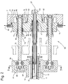
- Fig. 1 illustrated preferred embodiment of the invertible filter centrifuge comprises a the entire process space tightly enclosing housing 1, which is connected to a stationary machine frame 2, in which a hollow shaft 3 in main bearings 4, 5 is rotatably mounted.
- a hollow shaft 3 in main bearings 4, 5 is rotatably mounted.
- This in Fig. 1 located on the right, on the main bearing 5 protruding end of the hollow shaft 3 is rotatably connected to a drive wheel 7, via which the hollow shaft 3, for example by means of a belt 6, by a motor 8 in circulation is displaceable.
- the rigidly continuous between the main bearings 4, 5 hollow shaft 3 has an axially directed keyway 10, in which a wedge piece 9 is axially displaceable.
- This wedge piece 9 is rigidly connected to a displaceable inside the hollow shaft 3 thrust shaft 12.
- the thrust shaft 12 therefore rotates together with the hollow shaft 3, but is axially displaceable in this.
- the hollow shaft 3 and the thrust shaft 12 extend in one of the holder of the main bearing 4, 5 serving support body 13 which is supported on the machine frame 2.
- a filter drum 16 is flanged with its bottom 17 rotationally fixed.
- the filter drum 16 On its cylindrical outer wall, the filter drum 16 has radially extending passage openings 18.
- the filter drum 16 On its side opposite the bottom 17, the filter drum 16 is open.
- flange-like opening edge 19 is clamped by means of a retaining ring 21 of an edge of a substantially cylindrically shaped filter cloth 22 tightly.
- the other edge of the filter cloth 22 is connected in a corresponding manner tight with the sliding floor 23, which is rigidly connected to the displaceable, the bottom 17 freely penetrating shear shaft 12.
- an inlet channel 26 is provided, which serves for supplying a suspension to be separated into its solid and liquid constituents, or of washing liquid.
- the inlet channel 26 is connected via the inlet tube 51 and the entire thrust shaft 12 penetrating opening 15 with the centrifugal space 14.
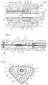
- An in Fig. 2 illustrated drive means 69 includes, for example, two symmetrically arranged, synchronously with the same speed rotating ringspindelachsen 70 and 71, which cause the axial thrust movement of the thrust plate 74.
- the drive device is described below with reference to a screw spindle axis, wherein the screw spindle axes, since they consist of the same machine elements as a result of the symmetrical arrangement, are marked on one side only with position numbers.
- a threaded spindle 72 is supported on the left side by a arranged in the support body 13 bearing 84 and rigidly connected via a wedge with a spindle wheel 86, which, as Fig. 7 shows, via intermediate wheels 87 in a directly connected to a motor 89 drive wheel 88 engages.
- This exemplified embodiment of a synchronous drive of the two threaded spindles 72 can also by other known non-positive Transmission systems, such as chain or timing belt drives, to be replaced.
- the threaded spindle 72 is supported on the right side by a bearing 85 arranged in the machine frame 2.
- the external thread of the threaded spindle 72 engages in a provided with a corresponding internal thread threaded bushing 73 which is rotatably connected via a conventional feather key 94, but slightly axially displaceable, connected to the thrust plate 74.
- a plate spring 76 and 75 is arranged, which biases the threaded bushing 73 relative to the thrust plate 74, wherein said keyway 94 a slight axial movement between the threaded bushing 73 and thrust plate 74 to the left or right allows.
- the 90 and 91 projecting at right angles on both sides of the threaded bushing 73 is either shifted to the right depending on the respective operating state (shown with solid line) or the front collar 90 and 91 is shifted to the left (shown with dashed line).
- the pusher plate 74 is shifted to the right (in Fig. 1 and 2 shown with a solid line) and rests with a contact surface 93 on a stop surface 77 of the machine frame 2, and is centered in this position with a of the contact surface 93 projecting circular collar 82 in a receiving bore 83 of the machine frame 2.
- the centrifugal chamber cover 25 with its centrifugal space seal 20 sealingly inserted into the retaining ring 21 at the opening edge 19 of the filter drum 16 and thus the centrifugal chamber 14 is closed.
- the thrust plate 74 is rigidly and self-lockingly connected in this operating state with the machine frame 2 by a plurality of grooves 79 slidably disposed in grooves 79 via wedge surfaces 78.
- the rigid locking of the thrust plate 74 with the machine frame 2 can also be performed by other known clamping elements.
- the rotatably mounted thrust shaft 12 is axially connected via the thrust bearings 45 and 46 with the radially rigid thrust plate 74 at the right end, so that the thrust plate 74 and the thrust shaft 12 are axially displaceable together.
- One arranged between the thrust shaft 12 and thrust plate 74 seal 47, preferably a mechanical seal, are preceded by one or more protection zones.
- protection zone 48 is connected via a supply line 43 with an inflow valve, not shown, which may optionally be open or closed, connected to a compressed gas source, and connected via a gap 54 with the opening 15 of the thrust shaft 12.
- a drain line 44 leads to a drain valve, not shown, which can be selectively opened or closed.
- the protection zone 49 is supplied via a supply line 41 to an inflow valve, not shown, which may be open or closed optionally, with a suitable liquid for cleaning purposes. From the protection zone 49 leads a drain line 42 to a drain valve, not shown, which may be open or closed optionally.
- the pusher plate 74 is rigidly connected to the inlet tube 51 on the right and projects into the opening 15 of the pusher shaft 12 on the left. At the right end of the thrust shaft 12, the opening 15 is narrowed by a shoulder 40 to a smaller passage.
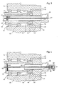
- a breather tube 50 is rigidly connected to the pusher plate 74 on the right, penetrates the inlet tube 51 along the entire length, and then projects into the opening 15. Furthermore, the thin vibration sensitive vent tube 50 is supported by support struts 52 on the inner wall of the inlet tube 51. For vibration-related reasons, the inlet pipe 51 can not be performed with the located in its center vent pipe 50 to the centrifugal chamber 14. Depending on the suspension to be filtered, however, it is advantageous to connect the centrifugal chamber 14 directly to a venting port 57 via the venting tube 50.
- Fig. 4 shows opposite Fig. 3 a more elaborate embodiment in which a long, the entire opening 15 in the thrust shaft 12 and the inlet pipe 51 penetrating vent pipe 50 the centrifugal space 14 via a connecting space 58 directly to the vent port 57 and a valve, not shown, which may be open or closed, combines.
- the vent tube 50 is supported with a plurality of radially and axially distributed support struts 53 on the inner wall of the thrust shaft 12 and runs together with her.
- At the right end of the vent tube 50 is collected by a support bearing 56, further separates a sealing ring 55 the inlet channel 26 from the connecting space 58th
- Fig. 5 shows another opposite 3 and 4 modified embodiment.
- An inlet tube 51 projects in its shortest execution axially only slightly the radial shoulder 40 of the thrust shaft 12, and is limited in its longest embodiment (shown by broken line drawn) by vibration-induced influences.
- the centrifugal space 14 is connected to a vent line 66.
- the vent line 66 may be open or closed.
- Fig. 6 shows an evolution of the in Fig. 3 illustrated embodiment.
- the left end of the static vent pipe 50 is fixedly connected to a connector 59, the bore 67 receives the right end of a peripheral with the thrust shaft 12 vent pipe extension 68 and supported by a bearing 60.
- the circumferential vent tube extension 68 is sealed by a labyrinth 61, or other conventional sealing system, not shown, against a radially static connector 59.
- centrifugal space 14 is connected via the vent pipe extension 68 and the vent pipe 50 directly to the vent port 57.
- Fig. 8 shows one opposite Fig. 1 modified embodiment of the solids collection chamber 32.
- the left-hand end wall of the housing 1 has a large-sized access opening 34 which is closed by a cover 28.
- the cover 28 may be formed transparent in a large area 29, so that even in the closed state of the solids collection space 32 is inspected.
- a transparent insert 27 is mounted in the centrifugal chamber cover 25, so that even with the solids collection chamber 32 closed the centrifugal chamber 14 can be viewed from the outside.
- the housing 1 about a vertical axis 97 which passes through a projection 95 on the housing 1 and a projection 96 on the machine frame 2, pivotally.
- the housing 1 can be pivoted to the left in an open position, not shown, so that a completely unobstructed access to the filter drum 16, solids collection chamber 32, filtrate collection chamber 31 and the two spaces delimiting partition 33 is possible.
- the housing 1 is connected by means of known elements of mechanical engineering, for example screw or quick release, with the interposition of a seal, with the machine frame 2.
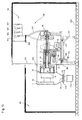
- Revolving filter centrifuge shown shows a list in which the process space enclosed by the housing 1, consisting of the centrifugal space 14, filtrate collecting space 31 and solids collecting space 32, projects through a building partition 100 into a clean room 101.
- a solids outlet opening 36 is connected by a separable closure device 110 with a solids container 115, wherein in a separation, a closure upper part 111 closes the housing 1 tightly and a closure bottom 112 remains on the uncoupled solids container 115.
- the filtrate is discharged through an outgoing from the filtrate collection chamber 31, the machine frame 2 traversing Filtratabschreibtechnisch 114.
- the machine frame 2 including the assemblies associated with it, supporting body 13 with the main bearings 4 and 5, translational drive with the motor 89, and rotational drive with the motor 8, with the interposition of bearings 106 and 107 is mounted on a support frame 117, the in turn anchored to the floor 105 of the engine room 102.
- the entire media supply equipment 120 is installed in the engine room 102.
- the translationally moving inlet channel 26 is connected via a flexible hose 121, with a stationary transfer point 123, to which the entire media supply lines with their associated valves, in this embodiment, in each case a valve for suspension 124, wash liquid 125, compressed gas 126 and vent 127, coupled are.
- Fig. 11 shows opposite Fig. 10 a further developed embodiment.
- the housing 1 projecting into the clean room 101 and comprising the process chamber of the invertible filter centrifuge is in turn enclosed by a glove box 130.
- large-scale lenses 133 are used, which are each provided with a plurality of openings 131 (shown two) are provided.
- highly flexible gloves 132 are incorporated in a gas-tight manner by means of which an operator 134 can work inside the glove box 130 without contaminating the clean room 101.
- the housing 1 can be used together with the glove box 130 around the in Fig. 9 shown axis 97 are pivoted.
- the housing 1 is connected by means of known elements of mechanical engineering, for example screw or quick release, with the interposition of a seal, with the machine frame 2.
- the invertible filter centrifuge first takes the in Fig. 1 by means of a solid line shown operating position.
- the displaceable pusher shaft 12 is retracted into the hollow shaft 3, whereby the push floor 23 connected to the pusher shaft 12 is located near the bottom 17 of the filter drum 16, and the filter cloth 22 is inverted into the filter drum 16 so as to be in its interior.
- the centrifugal chamber cover 25 has with its centrifugal space seal 20, sealing in the retaining ring 21 on Opening edge 19 of the filter drum 16 is inserted.
- the suspension to be filtered is introduced through the inlet channel 26, the inlet tube 51 and the opening 15 in the pusher shaft 12.
- the centrifugal space 14 is kept unpressurized via the venting tube 50 and via the connection 57, which is connected to a valve that is not shown but open during the filling process.
- the liquid components of the suspension pass in the direction of the arrows 35 through the passage openings 18 of the filter drum 16 and are passed into a filtrate outlet opening 37.
- the solid particles of the suspension are held up by the filter cloth 22.
- the invertible filter centrifuge is transferred to two operating states.
- the transition of the two in Fig. 1 and 2 shown operating conditions, centrifugal 14 closed (shown by solid line) and centrifugal 14 open (shown by broken line drawn) is mediated by the drive means 69.
- the pusher plate 74 before it comes to the stop surface 77 of the machine frame 2 to the plant, by collecting bolts which protrude from the machine frame 2 and penetrate into the corresponding counterparts in her, collected.
- the thrust plate 74 is supported on its entire travel by means of a stable guide.
- the displaceably mounted threaded sleeve 73 moves from its left position (in FIG. 2 shown with dash-dotted line) against the bias of the plate spring 76 in the right position (shown by solid line), so that after completion of the rotation between the right Stirnbund 91 and the threaded bush 73 arranged plate spring 75 is relaxed and the thrust plate 74 through the Force of the plate spring 76 is pressed against the stop surface 77 of the machine frame 2.
- the force generated by the plate spring 76 is also at the same time the maximum locking force for the centrifugal chamber 14. This force is alsrecherhalten even after switching off the motor 89 through the self-locking screw 72.
- a thrust shaft 12 surrounding and rotating with it, the axial displacement permitting, against the ambient atmosphere tightly delineating protective device, for example Bellows, provided which prevents a germ-free or sterile production connection between the process area in the housing 1 and the surrounding atmosphere.
- a surrounding the threaded spindle, against contamination protective the axial movement permitting protective device, for example a bellows, provided.
- the two threaded bushings 73 are not arranged directly in the thrust plate 74, but in a pendulum piece, which is connected via a pivot axis, the center of which intersects the shear shaft center with the thrust plate 74.
- a different force build-up in the fferspindelnachsen 70 and 71 is avoided by a slight pivotal movement of the shuttle.
- the threaded bushes 73 are integrated in the thrust plate so that they can also perform a slight pendulum motion.
- the threaded spindle is a spindle without self-locking, for example, a conventional ball screw.
- the locking force required for the safe locking of the centrifugal chamber 14 is applied either by the constantly switched-on motor 89 or by a switchable to the appropriate place in the drive train brake.
- the fferably shaped ringspindelachsen 70 and 71 are replaced by cheaper hydraulic lifting cylinder under in Kability the leak-based disadvantages.
- the drive means 69 instead of two fferspindelachsen, as in Fig. 2 shown, realized on one side with a screw spindle axis.
- a disadvantage of this cost-effective variant is the transverse force that occurs, which leads to increased wear in the translation bearings, which support the displaceable shear shaft 12.
- the drive device consists of a screw spindle axis, which is arranged centrally in an extension of the thrust shaft 12.
- a disadvantage of this cost-effective design is that the overall length of the invertible filter centrifuge increases at least by the travel path of the thrust shaft 12.
- the thrust plate 74 is connected by a detachable, but self-locking in the closed state lock with the machine frame 2, with the advantage that the force required to hold the centrifugal space 14 is not absorbed by the fferspindelachsen 70 and 71, but is collected directly over the thrust plate 74 of the stable machine frame 2.
- Another significant advantage of this embodiment is a serious improvement of the dynamic behavior of the thrust plate 74, with its vibration sensitive internals, seal 47, inlet tube 51 and vent tube 50 (in Fig. 3, 4 . 5 and 6 shown) during its assembly with the machine frame 2.
- the inlet tube 51 and the vent tube 50 can be formed much longer.
- the centrifugal chamber 14 closed by inserting the centrifugal chamber cover 25 with the associated centrifugal chamber seal 20, and the positioning in the axial direction by the fixed system of the thrust plate 74 on the machine frame 2.
- the axial force generated by the drive means 69 must be at least as large be as the under unfavorable conditions due to the approved operating parameters resulting axial component of adjusting itself in the centrifugal chamber 14 hydraulic force.
- the axial component is caused by the difference in area between the centrifugal chamber cover 25 and the sliding floor 23, which laterally delimit the centrifugal space 14.
- the maximum component occurs only when at maximum spin speed and full filter drum only slowly a filter cake build-up takes place, a rare occurrence that occurs only in low-solids suspensions.
- the locking plate 74 is connected to the machine frame 2 locking released and initiated by turning on the motor 89, an axial movement of the thrust plate 74 to the left.
- the displaceably mounted threaded bushing 73 in Fig. 2 from its right position (shown with a solid line) as long as to the left until the arranged between the end collar 91 and the threaded bush 73 plate spring 75 is tensioned and the (in Fig. 2 with dash-dotted line drawn) assumes position.
- pressurized gas in particular inert gas
- inert gas can be introduced into the centrifugal space 14 of the filter drum 16 after the suspension has been introduced.
- the internal pressure caused thereby in the filter drum 16 increases the hydraulic pressure arising in the centrifugal force field of the rotating filter drum 16 and thereby has a favorable overall effect on the filtration result.
- inlet channel 26 it is also possible through the inlet channel 26 to introduce steam into the filter drum 16 and thereby subject the adhering to the filter cloth 22 filter cake a steam wash. It is also possible to extract an active substance by extraction from the adjacent solid.
- an overpressure in the filter drum 16 instead of an overpressure in the filter drum 16 to generate a negative pressure, for example, characterized in that via the inlet channel 26 of the centrifugal chamber 14 is connected to a suction device, not shown. Such a temporary introduced negative pressure can for example have a favorable effect on the filtration behavior of the filter cake.
- seal Any type of seal that can be used at this point, whether gas or liquid lubricated mechanical seal, lip seal, or any other known Sealing element, is intrinsically that it at its critical point at which the relative movement between the static and the rotating component takes place, although it itself generates abrasion, very sensitive to the addition of foreign matter, that is, pollution reacts.
- measures are taken according to the invention against contamination, it is prevented that foreign matter can attach to the sensitive area of the seal 47.
- the supplied through the inlet channel 26 suspension is passed through the inlet tube 51 via the opening 15 in the thrust shaft 12 to the centrifugal space 14.
- the flow behavior of the suspension in the opening 15 in the thrust shaft 12 creates a uniform liquid ring, which is prevented on the right side by the shoulder 40 at a further spread, and how Fig. 1 shows on the left side in the centrifugal chamber 14 flows.
- the opening 15 in the thrust shaft 12 is not in the Fig. 3 paragraph 40 provided, but narrowed at the right end and increases in the course of their extension to the other side, so that they expanded into the centrifugal chamber 14 opens, or the entire machine design is designed so that the centrifuge axis to the centrifugal chamber 14 tends.
- Such embodiments is inherent in that after completion of the suspension or washing liquid supply, a self-emptying through the opening 15 in the thrust shaft 12 occurs.
- FIG. 3 How out Fig. 3 can be seen by gas supply to the protection zone 48, a barrier gas flow in which the radially static inlet tube 51 from the rotating shear shaft 12 separating gap 54 generated, and thereby prevents penetration of suspension in the shaft seal 47 upstream protection zones 48 and 49.
- the solid cake built up in the centrifugal space 14 is flowed through by a washing liquid introduced via the inlet channel 26, in accordance with a centrifuging time dependent on the product to be processed.
- the supply of washing liquid, or only one Subset, can also be done via the supply line 43, and thus at the same time as a cleaning liquid for the protection zone 48, the gap 54 and the opening 15 in the thrust shaft 12 are effective.
- the upstream of the supply line 43 not shown inflow valve, in this case, a three-way valve that allows either gas or scrubbing liquid supply.
- thrust plate 74, inlet tube 51 and vent tube 50 are rigidly connected during filling and centrifuging and thus vibration stable with the machine frame 2, the vent tube 50, as Fig. 1 and 3 shows, although run very long, but for lack of sufficient stability, it does not extend to the centrifugal space 14th
- Fig. 4 . 5 and 6 are in conjunction with Fig. 1 across from Fig. 3 more elaborate embodiments shown, in which, however, advantageously a direct connection from the rotating centrifugal chamber 14 via the connecting space 58th given to the radial static vent port 57, or, as shown Fig. 5 can be seen, the direct connection leads via the gap 65 to the vent line 66.
- Fig. 5 shown channels 63 in the thrust shaft 12 just before its end facing away from the centrifugal chamber 14, for example, through a pipe to the shear shaft center and summarized there in a central tube, which then extends through the inlet tube 51, the inlet channel 26 toward the connecting space 58, the makes a direct connection to the vent port 57, and thus a direct connection of the rotating centrifugal space 14 is given to the radially static vent port 57.
- venting port 57, and the vent line 66 upstream, not shown valve formed as a three-way valve, which optionally allows a gas or washing liquid supply.
- FIG Fig. 10 and 11 The operation of a system which is governed by the idea of avoiding as much as possible cross-contamination between the product and the environment is shown by the embodiments in FIG Fig. 10 and 11 , with a split installation of the invertible filter centrifuge, in which the process space in a clean room 101, and the machine frame 2 with the storage, the drives, as well as the entire media supply equipment 120, is located in a machine room 102.
- the invertible filter centrifuge is stationarily mounted with its machine frame 2 via vibration bearings 106 and 107 in the machine room 102 and projects with its process space through the building partition 100, with which it is coupled via flexible, gas-tight connection elements 103 and 104, into the clean room 101 into it.
- the cross sections of the media leading passages for example, the opening 15 in the thrust shaft 12
- the gas flow rate can be increased when working in the centrifugal chamber 14 with positive or negative pressure, or when the solid cake flows through for drying with gas which leads to a very advantageous reduction of the cycle time and thus an increase in production.
- a device for example a fill level sensor, microwave transmitter, sampling device or another auxiliary device, can be introduced into the centrifugal space 14 through the end face of the housing 1, the solids collecting space 32, and the centrifugal chamber cover 25 within an enclosure, for example a pipe.
- the housing 1 enclosing the process space is connected to the solids container 115 at its solids discharge opening 36 via a divisible closure device 110 consisting of an upper part 111 and a lower part 112.
- a divisible closure device 110 consisting of an upper part 111 and a lower part 112.
- the flap in the closure device 110 is closed, and then the closure device 110 separated, while the housing 1 remains gas-tightly closed by the upper closure part 111 remaining there, like the solid container 115 with its closure lower part 112 located on it.
- the solid container 115 can now be handled in the closed state, and can be supplied to its further destination, to the exclusion of cross contamination. At the separation point another, empty solid container 115 is docked. In this approach, without interrupting production, the Solid be discharged from the solids collection chamber 32 without contamination.
- FIG. 11 A further development of the invertible filter centrifuge according to the invention is made Fig. 11 seen.
- the housing 1 enclosing the process space is in turn enclosed by a glove box 130.
- Through openings 131 which are connected to highly flexible gloves can be intervened by hatches, not shown, in the illustrated with broken line drawn part of the housing 1 by an operator 134 by means of gloves 132 in the process space. It is thus possible to carry out the periodically occurring change of the filter cloth 22 as well as the sporadically occurring changing of the centrifugal space seal 20 with closed process space and thus without decontamination effort, since in these works, the separation between the process room and clean room is not canceled.
- the hatches in the housing 1, not shown, through which the operator engages 134 in the process space, are also provided with lids, not shown, which are designed so that they can handle the operator 134 within the glove box 130.
- the operator 134 can both open and close the hatch, it being advantageous that the hatch only dust-tight, but not gas-tight, since the gas-tight separation between the process room and the clean room through the glove box is effected.
- the solids container 115 is not docked to the housing 1, but positioned separately below the solids outlet opening 36.
- the solids container 115 is designed in this embodiment with a plastic bag, which is closed after receiving the solid as well as the solid container 115 itself.
- the Transfer area also integrated in a glove box.
- the solid container 115 is located in a separate glove box, and is moved through a lock in the clean room 101.
Landscapes
- Centrifugal Separators (AREA)
- Lubrication Details And Ventilation Of Internal Combustion Engines (AREA)
Applications Claiming Priority (3)
| Application Number | Priority Date | Filing Date | Title |
|---|---|---|---|
| DE10311997 | 2003-03-19 | ||
| DE10311997A DE10311997A1 (de) | 2003-03-19 | 2003-03-19 | Stülpfilterzentrifuge |
| PCT/DE2004/000408 WO2004082843A1 (de) | 2003-03-19 | 2004-03-04 | Stülpfilterzentrifuge |
Publications (2)
| Publication Number | Publication Date |
|---|---|
| EP1603679A1 EP1603679A1 (de) | 2005-12-14 |
| EP1603679B1 true EP1603679B1 (de) | 2008-07-23 |
Family
ID=32945963
Family Applications (1)
| Application Number | Title | Priority Date | Filing Date |
|---|---|---|---|
| EP04717019A Expired - Lifetime EP1603679B1 (de) | 2003-03-19 | 2004-03-04 | Stülpfilterzentrifuge |
Country Status (7)
| Country | Link |
|---|---|
| US (1) | US7168571B2 (ja) |
| EP (1) | EP1603679B1 (ja) |
| JP (1) | JP4431569B2 (ja) |
| CN (1) | CN100408194C (ja) |
| AT (1) | ATE401960T1 (ja) |
| DE (2) | DE10311997A1 (ja) |
| WO (1) | WO2004082843A1 (ja) |
Families Citing this family (35)
| Publication number | Priority date | Publication date | Assignee | Title |
|---|---|---|---|---|
| US7396324B2 (en) * | 2003-10-17 | 2008-07-08 | Hitachi Koki Co., Ltd. | Centrifugal separator with first and second control panels |
| DE102006009200A1 (de) * | 2006-02-22 | 2007-08-30 | Fima Maschinenbau Gmbh | Verfahren für den Betrieb einer Zentrifuge |
| JP4799221B2 (ja) * | 2006-03-06 | 2011-10-26 | 三洋電機株式会社 | アイソレータ用インキュベータ |
| DE102006011895A1 (de) * | 2006-03-15 | 2007-09-20 | Westfalia Separator Ag | Separatoranordnung in sanitärer Ausführung |
| DE102007038692A1 (de) * | 2007-02-28 | 2008-09-04 | Richard Denk | Verfahren und Vorrichtung zum kontaminationsfreien Beschicken und Entleeren |
| DE102007017982A1 (de) * | 2007-04-05 | 2008-10-09 | Heinkel Process Technology Gmbh | Zentrifugenvorrichtung |
| DE102007039759B3 (de) * | 2007-08-22 | 2009-04-09 | Richard Denk | Verfahren und Vorrichtung zum kontaminationsfreien Beschicken und Entleeren |
| US20090176638A1 (en) * | 2007-10-23 | 2009-07-09 | John Di Bella | Gas sealed apparatus for separating solids, liquids and gases having different specific gravities |
| WO2009123350A1 (ja) * | 2008-04-04 | 2009-10-08 | 株式会社 城 | 結晶ろ過の方法および装置 |
| WO2010020285A1 (de) * | 2008-08-21 | 2010-02-25 | Ferrum Ag | Verfahren zum waschen eines feststoffkuchens, sowie zentrifuge |
| US8409337B1 (en) | 2010-06-08 | 2013-04-02 | Aaf-Mcquay Inc. | Air handling filtration equipment with adjustable media bed and method of use |
| JP5626455B2 (ja) * | 2011-03-31 | 2014-11-19 | アイシン・エィ・ダブリュ株式会社 | 動力伝達装置 |
| DE102013006411B4 (de) * | 2013-04-13 | 2018-10-04 | Hosokawa Alpine Aktiengesellschaft | Verfahrenstechnische Maschine zur Installation in eine Wand |
| AU2013403312B2 (en) * | 2013-10-14 | 2015-09-03 | Halliburton Energy Services, Inc. | Flexure membrane for drilling fluid test system |
| CN103639075A (zh) * | 2013-12-18 | 2014-03-19 | 常州普莱克红梅色母料有限公司 | 一种色母料生产用离心脱水装置 |
| GB2554195B (en) | 2015-04-24 | 2021-04-07 | Halliburton Energy Services Inc | Removal of fine solids from oilfield fluids |
| CN105107646B (zh) * | 2015-09-15 | 2017-12-22 | 张家港市中南化工机械有限公司 | 一种翻袋离心机 |
| CN105499527B (zh) * | 2015-12-11 | 2017-10-10 | 西南铝业(集团)有限责任公司 | 玻布袋空气振动机构 |
| JP6618433B2 (ja) * | 2016-07-05 | 2019-12-11 | 月島機械株式会社 | 遠心分離装置および遠心分離方法 |
| JP6578254B2 (ja) * | 2016-07-05 | 2019-09-18 | 月島機械株式会社 | 遠心分離装置および遠心分離方法 |
| CN106423593A (zh) * | 2016-09-26 | 2017-02-22 | 江苏华大离心机制造有限公司 | 一种卧式刮刀卸料离心机中残余滤饼的清除方法及滤布的驱动机构 |
| AU2018224318A1 (en) | 2017-02-27 | 2019-09-19 | Translate Bio, Inc. | Methods for purification of messenger RNA |
| JP2021506576A (ja) * | 2017-12-19 | 2021-02-22 | ゼロス リミテッド | 処理装置のためのろ過器 |
| US10506912B2 (en) * | 2018-05-16 | 2019-12-17 | Haier Us Appliance Solutions, Inc. | Dishwasher appliance with vent duct mixing |
| CN109046808B (zh) * | 2018-10-11 | 2023-12-19 | 江苏蓝鸟离心机制造有限公司 | 一种立式刮刀离心机进料处理装置 |
| EP3666389B1 (en) * | 2018-12-10 | 2021-08-04 | Alfa Laval Corporate AB | Centrifugal separator |
| JP7161199B2 (ja) * | 2019-03-19 | 2022-10-26 | 株式会社松本機械製作所 | 遠心分離装置 |
| KR20220086586A (ko) * | 2019-10-31 | 2022-06-23 | 베하에스-존트호펜 게엠베하 | 회전형 압력 필터 |
| KR102504657B1 (ko) * | 2019-11-18 | 2023-02-27 | 주식회사 엘지화학 | 가압 원심 탈수기 |
| CN111185044B (zh) * | 2020-01-13 | 2021-12-17 | 兰石生 | 一种纺织污水处理系统 |
| CN111686944A (zh) * | 2020-06-24 | 2020-09-22 | 台州职业技术学院 | 一种fwz型翻袋式离心机、控制方法及应用 |
| WO2022072836A2 (en) | 2020-10-01 | 2022-04-07 | Translate Bio, Inc. | Methods for purification of messenger rna |
| CN113171886A (zh) * | 2021-04-06 | 2021-07-27 | 湖北雪飞化工有限公司 | 一种用于硝化棉生产的翻袋离心机 |
| CN113522544B (zh) * | 2021-07-21 | 2022-03-25 | 江苏赛德力制药机械制造有限公司 | 一种翻袋卸料离心机驱动机构 |
| CN114178057B (zh) * | 2021-12-08 | 2023-03-31 | 广州贝特生物科技有限公司 | 一种稳定型高速冷冻离心机以及使用方法 |
Family Cites Families (10)
| Publication number | Priority date | Publication date | Assignee | Title |
|---|---|---|---|---|
| DE2631160A1 (de) * | 1976-07-10 | 1978-01-12 | Erwin Biesinger | Schleudervorrichtung, insbesondere zur nachbehandlung von noch fliessfaehigem filterschlamm |
| JPS5665646A (en) * | 1979-11-02 | 1981-06-03 | Takashi Mukai | Filter-separation mechanism |
| CN85100169B (zh) * | 1985-04-01 | 1985-09-10 | 中南制药机械厂 | 旁滤式自动离心机 |
| FR2641715B1 (fr) * | 1989-01-19 | 1991-04-12 | Robatel Slpi | Essoreuse centrifuge a cuve articulee pour filtration en atmosphere sterile |
| DE3916266C1 (ja) * | 1989-05-19 | 1990-08-30 | Heinkel Industriezentrifugen Gmbh + Co, 7120 Bietigheim-Bissingen, De | |
| ES2073038T3 (es) * | 1990-09-24 | 1995-08-01 | Heinkel Ind Zentrifugen | Centrifuga de filtro reversible. |
| DE19646038C2 (de) * | 1996-11-08 | 1998-08-06 | Heinkel Ind Zentrifugen | Stülpfilterzentrifuge |
| US6159360A (en) * | 1996-11-22 | 2000-12-12 | Heinkel Industriezentrifugen Gmbh & Co. | Invertible filter centrifuge including a solids drier |
| DE19732006C1 (de) * | 1997-07-25 | 1998-11-19 | Heinkel Ind Zentrifugen | Vorrichtung zur Durchführung einer Gewichtsmessung bei Zentrifugen |
| DE10115381A1 (de) * | 2001-03-28 | 2002-10-24 | Heinkel Ag | Stülpfilterzentrifuge |
-
2003
- 2003-03-19 DE DE10311997A patent/DE10311997A1/de not_active Withdrawn
-
2004
- 2004-03-04 DE DE502004007671T patent/DE502004007671D1/de not_active Expired - Lifetime
- 2004-03-04 CN CNB2004800064845A patent/CN100408194C/zh not_active Expired - Fee Related
- 2004-03-04 AT AT04717019T patent/ATE401960T1/de not_active IP Right Cessation
- 2004-03-04 EP EP04717019A patent/EP1603679B1/de not_active Expired - Lifetime
- 2004-03-04 US US10/549,361 patent/US7168571B2/en not_active Expired - Fee Related
- 2004-03-04 WO PCT/DE2004/000408 patent/WO2004082843A1/de active IP Right Grant
- 2004-03-04 JP JP2006504246A patent/JP4431569B2/ja not_active Expired - Fee Related
Also Published As
| Publication number | Publication date |
|---|---|
| DE10311997A1 (de) | 2004-10-07 |
| EP1603679A1 (de) | 2005-12-14 |
| JP2006520261A (ja) | 2006-09-07 |
| US20060175245A1 (en) | 2006-08-10 |
| DE502004007671D1 (de) | 2008-09-04 |
| CN1758963A (zh) | 2006-04-12 |
| WO2004082843A1 (de) | 2004-09-30 |
| CN100408194C (zh) | 2008-08-06 |
| US7168571B2 (en) | 2007-01-30 |
| ATE401960T1 (de) | 2008-08-15 |
| JP4431569B2 (ja) | 2010-03-17 |
Similar Documents
| Publication | Publication Date | Title |
|---|---|---|
| EP1603679B1 (de) | Stülpfilterzentrifuge | |
| EP1399237B1 (de) | Drehfilteranlage | |
| EP0936948B1 (de) | Stülpfilterzentrifuge | |
| EP0387278B1 (de) | Stülpfilterzentrifuge | |
| EP0472554B1 (de) | Stülpfilterzentrifuge | |
| EP1372862A1 (de) | Schubzentrifuge | |
| DE2709894A1 (de) | Filterzentrifuge | |
| EP0551252B1 (de) | Stülpfilterzentrifuge | |
| DE4337618C1 (de) | Stülpfilterzentrifuge (Trommelraumabdichtung) | |
| DE4342471C1 (de) | Filterzentrifuge | |
| DE10005796A1 (de) | Drehfilteranlage | |
| DE10245013A1 (de) | Filterzentrifuge | |
| DE102011010072B4 (de) | Stülpfilterzentrifuge | |
| DE4417310C1 (de) | Filterzentrifuge | |
| DE3430508C2 (ja) | ||
| DE19542763C1 (de) | Stülpfilterzentrifuge | |
| DE19705788C1 (de) | Diskontinuierlich arbeitende Filterzentrifuge | |
| DE19611129C1 (de) | Druckbeaufschlagte Schubzentrifuge | |
| DE19848064A1 (de) | Trommelfilterpresse für Suspensionen | |
| DE102015003058B3 (de) | Stülpfilterzentrifuge | |
| DE2343724C3 (de) | Flüssigkeitsabdichtung für rotierende Wellen | |
| DE8420440U1 (de) | Ueberlauf-separationszentrifuge | |
| DE20304849U1 (de) | Stülpfilterzentrifuge |
Legal Events
| Date | Code | Title | Description |
|---|---|---|---|
| PUAI | Public reference made under article 153(3) epc to a published international application that has entered the european phase |
Free format text: ORIGINAL CODE: 0009012 |
|
| 17P | Request for examination filed |
Effective date: 20050812 |
|
| AK | Designated contracting states |
Kind code of ref document: A1 Designated state(s): AT BE BG CH CY CZ DE DK EE ES FI FR GB GR HU IE IT LI LU MC NL PL PT RO SE SI SK TR |
|
| AX | Request for extension of the european patent |
Extension state: AL LT LV MK |
|
| DAX | Request for extension of the european patent (deleted) | ||
| GRAP | Despatch of communication of intention to grant a patent |
Free format text: ORIGINAL CODE: EPIDOSNIGR1 |
|
| GRAS | Grant fee paid |
Free format text: ORIGINAL CODE: EPIDOSNIGR3 |
|
| GRAA | (expected) grant |
Free format text: ORIGINAL CODE: 0009210 |
|
| AK | Designated contracting states |
Kind code of ref document: B1 Designated state(s): AT BE BG CH CY CZ DE DK EE ES FI FR GB GR HU IE IT LI LU MC NL PL PT RO SE SI SK TR |
|
| REG | Reference to a national code |
Ref country code: GB Ref legal event code: FG4D Free format text: NOT ENGLISH |
|
| REG | Reference to a national code |
Ref country code: CH Ref legal event code: EP |
|
| REG | Reference to a national code |
Ref country code: IE Ref legal event code: FG4D Free format text: LANGUAGE OF EP DOCUMENT: GERMAN |
|
| REF | Corresponds to: |
Ref document number: 502004007671 Country of ref document: DE Date of ref document: 20080904 Kind code of ref document: P |
|
| NLV1 | Nl: lapsed or annulled due to failure to fulfill the requirements of art. 29p and 29m of the patents act | ||
| PG25 | Lapsed in a contracting state [announced via postgrant information from national office to epo] |
Ref country code: ES Free format text: LAPSE BECAUSE OF FAILURE TO SUBMIT A TRANSLATION OF THE DESCRIPTION OR TO PAY THE FEE WITHIN THE PRESCRIBED TIME-LIMIT Effective date: 20081103 Ref country code: PT Free format text: LAPSE BECAUSE OF FAILURE TO SUBMIT A TRANSLATION OF THE DESCRIPTION OR TO PAY THE FEE WITHIN THE PRESCRIBED TIME-LIMIT Effective date: 20081223 Ref country code: NL Free format text: LAPSE BECAUSE OF FAILURE TO SUBMIT A TRANSLATION OF THE DESCRIPTION OR TO PAY THE FEE WITHIN THE PRESCRIBED TIME-LIMIT Effective date: 20080723 |
|
| PG25 | Lapsed in a contracting state [announced via postgrant information from national office to epo] |
Ref country code: FI Free format text: LAPSE BECAUSE OF FAILURE TO SUBMIT A TRANSLATION OF THE DESCRIPTION OR TO PAY THE FEE WITHIN THE PRESCRIBED TIME-LIMIT Effective date: 20080723 Ref country code: BG Free format text: LAPSE BECAUSE OF FAILURE TO SUBMIT A TRANSLATION OF THE DESCRIPTION OR TO PAY THE FEE WITHIN THE PRESCRIBED TIME-LIMIT Effective date: 20081023 Ref country code: SI Free format text: LAPSE BECAUSE OF FAILURE TO SUBMIT A TRANSLATION OF THE DESCRIPTION OR TO PAY THE FEE WITHIN THE PRESCRIBED TIME-LIMIT Effective date: 20080723 |
|
| REG | Reference to a national code |
Ref country code: IE Ref legal event code: FD4D |
|
| PG25 | Lapsed in a contracting state [announced via postgrant information from national office to epo] |
Ref country code: EE Free format text: LAPSE BECAUSE OF FAILURE TO SUBMIT A TRANSLATION OF THE DESCRIPTION OR TO PAY THE FEE WITHIN THE PRESCRIBED TIME-LIMIT Effective date: 20080723 Ref country code: DK Free format text: LAPSE BECAUSE OF FAILURE TO SUBMIT A TRANSLATION OF THE DESCRIPTION OR TO PAY THE FEE WITHIN THE PRESCRIBED TIME-LIMIT Effective date: 20080723 Ref country code: IE Free format text: LAPSE BECAUSE OF FAILURE TO SUBMIT A TRANSLATION OF THE DESCRIPTION OR TO PAY THE FEE WITHIN THE PRESCRIBED TIME-LIMIT Effective date: 20080723 |
|
| PG25 | Lapsed in a contracting state [announced via postgrant information from national office to epo] |
Ref country code: RO Free format text: LAPSE BECAUSE OF FAILURE TO SUBMIT A TRANSLATION OF THE DESCRIPTION OR TO PAY THE FEE WITHIN THE PRESCRIBED TIME-LIMIT Effective date: 20080723 Ref country code: CZ Free format text: LAPSE BECAUSE OF FAILURE TO SUBMIT A TRANSLATION OF THE DESCRIPTION OR TO PAY THE FEE WITHIN THE PRESCRIBED TIME-LIMIT Effective date: 20080723 Ref country code: SK Free format text: LAPSE BECAUSE OF FAILURE TO SUBMIT A TRANSLATION OF THE DESCRIPTION OR TO PAY THE FEE WITHIN THE PRESCRIBED TIME-LIMIT Effective date: 20080723 |
|
| PLBE | No opposition filed within time limit |
Free format text: ORIGINAL CODE: 0009261 |
|
| STAA | Information on the status of an ep patent application or granted ep patent |
Free format text: STATUS: NO OPPOSITION FILED WITHIN TIME LIMIT |
|
| 26N | No opposition filed |
Effective date: 20090424 |
|
| BERE | Be: lapsed |
Owner name: GERTEIS, JOHANNES Effective date: 20090331 Owner name: MAYER, GERD Effective date: 20090331 |
|
| PG25 | Lapsed in a contracting state [announced via postgrant information from national office to epo] |
Ref country code: MC Free format text: LAPSE BECAUSE OF NON-PAYMENT OF DUE FEES Effective date: 20090331 |
|
| PG25 | Lapsed in a contracting state [announced via postgrant information from national office to epo] |
Ref country code: SE Free format text: LAPSE BECAUSE OF FAILURE TO SUBMIT A TRANSLATION OF THE DESCRIPTION OR TO PAY THE FEE WITHIN THE PRESCRIBED TIME-LIMIT Effective date: 20081023 |
|
| PG25 | Lapsed in a contracting state [announced via postgrant information from national office to epo] |
Ref country code: BE Free format text: LAPSE BECAUSE OF NON-PAYMENT OF DUE FEES Effective date: 20090331 |
|
| PG25 | Lapsed in a contracting state [announced via postgrant information from national office to epo] |
Ref country code: PL Free format text: LAPSE BECAUSE OF FAILURE TO SUBMIT A TRANSLATION OF THE DESCRIPTION OR TO PAY THE FEE WITHIN THE PRESCRIBED TIME-LIMIT Effective date: 20080723 |
|
| PG25 | Lapsed in a contracting state [announced via postgrant information from national office to epo] |
Ref country code: AT Free format text: LAPSE BECAUSE OF NON-PAYMENT OF DUE FEES Effective date: 20090304 |
|
| PG25 | Lapsed in a contracting state [announced via postgrant information from national office to epo] |
Ref country code: GR Free format text: LAPSE BECAUSE OF FAILURE TO SUBMIT A TRANSLATION OF THE DESCRIPTION OR TO PAY THE FEE WITHIN THE PRESCRIBED TIME-LIMIT Effective date: 20081024 |
|
| PG25 | Lapsed in a contracting state [announced via postgrant information from national office to epo] |
Ref country code: LU Free format text: LAPSE BECAUSE OF NON-PAYMENT OF DUE FEES Effective date: 20090304 |
|
| PG25 | Lapsed in a contracting state [announced via postgrant information from national office to epo] |
Ref country code: HU Free format text: LAPSE BECAUSE OF FAILURE TO SUBMIT A TRANSLATION OF THE DESCRIPTION OR TO PAY THE FEE WITHIN THE PRESCRIBED TIME-LIMIT Effective date: 20090124 |
|
| PG25 | Lapsed in a contracting state [announced via postgrant information from national office to epo] |
Ref country code: TR Free format text: LAPSE BECAUSE OF FAILURE TO SUBMIT A TRANSLATION OF THE DESCRIPTION OR TO PAY THE FEE WITHIN THE PRESCRIBED TIME-LIMIT Effective date: 20080723 |
|
| PG25 | Lapsed in a contracting state [announced via postgrant information from national office to epo] |
Ref country code: CY Free format text: LAPSE BECAUSE OF FAILURE TO SUBMIT A TRANSLATION OF THE DESCRIPTION OR TO PAY THE FEE WITHIN THE PRESCRIBED TIME-LIMIT Effective date: 20080723 |
|
| REG | Reference to a national code |
Ref country code: FR Ref legal event code: PLFP Year of fee payment: 13 |
|
| REG | Reference to a national code |
Ref country code: FR Ref legal event code: PLFP Year of fee payment: 14 |
|
| REG | Reference to a national code |
Ref country code: FR Ref legal event code: PLFP Year of fee payment: 15 |
|
| REG | Reference to a national code |
Ref country code: DE Ref legal event code: R082 Ref document number: 502004007671 Country of ref document: DE Representative=s name: SCHOEN, THILO, DIPL.-PHYS., DE |
|
| PGFP | Annual fee paid to national office [announced via postgrant information from national office to epo] |
Ref country code: CH Payment date: 20210324 Year of fee payment: 18 Ref country code: FR Payment date: 20210319 Year of fee payment: 18 |
|
| PGFP | Annual fee paid to national office [announced via postgrant information from national office to epo] |
Ref country code: GB Payment date: 20210324 Year of fee payment: 18 Ref country code: DE Payment date: 20210224 Year of fee payment: 18 |
|
| PGFP | Annual fee paid to national office [announced via postgrant information from national office to epo] |
Ref country code: IT Payment date: 20210331 Year of fee payment: 18 |
|
| REG | Reference to a national code |
Ref country code: DE Ref legal event code: R119 Ref document number: 502004007671 Country of ref document: DE |
|
| REG | Reference to a national code |
Ref country code: CH Ref legal event code: PL |
|
| GBPC | Gb: european patent ceased through non-payment of renewal fee |
Effective date: 20220304 |
|
| PG25 | Lapsed in a contracting state [announced via postgrant information from national office to epo] |
Ref country code: LI Free format text: LAPSE BECAUSE OF NON-PAYMENT OF DUE FEES Effective date: 20220331 Ref country code: GB Free format text: LAPSE BECAUSE OF NON-PAYMENT OF DUE FEES Effective date: 20220304 Ref country code: FR Free format text: LAPSE BECAUSE OF NON-PAYMENT OF DUE FEES Effective date: 20220331 Ref country code: DE Free format text: LAPSE BECAUSE OF NON-PAYMENT OF DUE FEES Effective date: 20221001 Ref country code: CH Free format text: LAPSE BECAUSE OF NON-PAYMENT OF DUE FEES Effective date: 20220331 |
|
| PG25 | Lapsed in a contracting state [announced via postgrant information from national office to epo] |
Ref country code: IT Free format text: LAPSE BECAUSE OF NON-PAYMENT OF DUE FEES Effective date: 20220304 |