EP1600567B1 - Ablaufrinne - Google Patents
Ablaufrinne Download PDFInfo
- Publication number
- EP1600567B1 EP1600567B1 EP05011209.3A EP05011209A EP1600567B1 EP 1600567 B1 EP1600567 B1 EP 1600567B1 EP 05011209 A EP05011209 A EP 05011209A EP 1600567 B1 EP1600567 B1 EP 1600567B1
- Authority
- EP
- European Patent Office
- Prior art keywords
- drain pan
- drainage channel
- channel according
- collar
- gutter
- Prior art date
- Legal status (The legal status is an assumption and is not a legal conclusion. Google has not performed a legal analysis and makes no representation as to the accuracy of the status listed.)
- Expired - Lifetime
Links
Images

Classifications
-
- E—FIXED CONSTRUCTIONS
- E03—WATER SUPPLY; SEWERAGE
- E03F—SEWERS; CESSPOOLS
- E03F3/00—Sewer pipe-line systems
- E03F3/04—Pipes or fittings specially adapted to sewers
- E03F3/046—Open sewage channels
-
- E—FIXED CONSTRUCTIONS
- E03—WATER SUPPLY; SEWERAGE
- E03F—SEWERS; CESSPOOLS
- E03F5/00—Sewerage structures
- E03F5/04—Gullies inlets, road sinks, floor drains with or without odour seals or sediment traps
- E03F5/0407—Floor drains for indoor use
- E03F5/0408—Floor drains for indoor use specially adapted for showers
-
- E—FIXED CONSTRUCTIONS
- E03—WATER SUPPLY; SEWERAGE
- E03F—SEWERS; CESSPOOLS
- E03F5/00—Sewerage structures
- E03F5/04—Gullies inlets, road sinks, floor drains with or without odour seals or sediment traps
- E03F2005/0412—Gullies inlets, road sinks, floor drains with or without odour seals or sediment traps with means for adjusting their position with respect to the surrounding surface
- E03F2005/0413—Gullies inlets, road sinks, floor drains with or without odour seals or sediment traps with means for adjusting their position with respect to the surrounding surface for height adjustment
Definitions
- the present invention relates to a gutter according to the preamble of claim 1.
- Gutter gutters of the aforementioned kind are sufficiently known cf. EP-A-0677622 , They mainly comprise an elongated drain pan with a grate and a drainage device, the drain pan can be embedded in the ground and preferably bordered with tiles flush.
- the leveling elements are preferably threaded rods, which are received on the edge of the drain pan by thread in retaining lugs. During installation, the drainage channel on the threaded rods is above the floor and can be adjusted to a desired height and position by turning it.
- the present invention is based, and has as its object to provide a gutter, which can be adjusted by leveling to the desired position, but whose leveling elements are designed much less sensitive to large loads occurring.
- this object is achieved by a gutter with the characterizing features of claim 1.
- Characterized in that the drain pan is equipped with an at least partially circumferential collar which is suitable for receiving the leveling elements, a much more stable receptacle for the leveling elements can be provided, so that deformations of the leveling elements are not expected.
- the collar is equipped with holes.
- the screed can be distributed through the free holes, whereby the installation of the gutter is much easier.
- the collar is designed as a polymer concrete slab.
- the gutter is advantageously suitable for fastening the leveling elements, preferably in the edge region of the polymer concrete slab.
- the drain pan is at least partially poured into the polymer concrete slab.
- the polymer concrete slab is at least partially equipped with a circumferential grid, which can be cast as a whole with the screed.
- the drain pan may comprise a floor with at least one slope, wherein the end of the slope a drain device is mounted.
- the liquid to be discharged is directed to the outlet device targeted.
- the drain pan is equipped with a circumferential projecting joint edge, wherein the distance between the collar and the upper end of the joint edge corresponds approximately to a tile height plus a tile adhesive used for the attachment of the tile.
- a circumferential projecting joint edge According to the configuration of the joint edge, an optimal connection surface for tiles is provided, which are to be laid around the gutter around. Overall, this results in a flat unit of tiles and gutter.
- the joint edge has a chamber which is formed between the joint edge and the circumferential collar.
- tile adhesive can be filled into the chamber.
- the gutter offers advantageously a drain grate, which is equipped with inlet slots and can be inserted into the drain pan.
- the drain pan is equipped with at least one luminaire arrangement.
- low-voltage lamps and / or light-emitting diodes are preferably used for safety-related aspects.
- the elongated extent of the gutter can advantageously be provided that the lamp assembly is disposed along the drain pan.
- the gutter can even be used as an optical guide.
- such a configured gutter can be used advantageously for optically demanding separation of a shower cubicle to the rest of the bathroom.
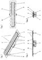
- a gutter 1 essentially comprises an elongate drain pan 3, which is equipped on the bottom side with a drain device 2 and closed by a drain grate 4, and leveling elements 6, which are adapted to position the drain pan 3 in a desired floor level and location.
- the drain grate 4 is equipped with inlet slots 7, through which the liquid can enter the drain pan 3.
- the drainage device 2 is arranged approximately in the middle of the drainage trough 3, wherein the trough bottom 13 is equipped with a slight gradient in the direction of the drainage device 2, so that it can be ensured that the liquid collects in the region of the drainage device 2.
- the gutter 1 is provided with a circumferential collar, which preferably extends around the entire gutter 1. It is envisaged that this collar is designed as a polymer concrete slab 11.
- the collar is designed as a sheet metal profile 8, wherein the leveling elements 6 are received in this sheet metal profile 8, preferably in the region of the outer collar edges.
- the sheet metal profile 8 is mounted, for this purpose already holes 15 are arranged within the sheet metal profile 8, which can accommodate the respective leveling element 6.
- both the sheet metal profile 8 and the holes 15 fulfill other functions.
- the sheet metal profile 8 serves as a holding element for the gutter 1 by the sheet metal profile 8 extends below the upper edge of the tub and can be cast together with the drain pan 3.
- the holes 15 are used to distribute a mounting mass, such as a screed.
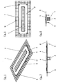
- the collar consists of a polymer concrete plate 11, in which the drain pan 3 is at least partially encapsulated.
- the leveling elements 6 are arranged in the region of the polymer concrete slab 11.
- a grid 12 is already cast in the polymer concrete slab 11, which lines the edge of the polymer concrete slab 11, so that the drain pan 3, the polymer concrete slab 11 and the grid 12 are aligned substantially along a plane.
- the grid 12, as well as partially the polymer concrete slab 11 is potted with the screed.
- Fig. 9 is now a side sectional view of an embodiment of the present invention according to the Fig. 5 to 8 shown.
- a circumferential edge 5 of the drain pan 3 can be seen, which extends above the polymer concrete slab 11.
- the height between the peripheral edge 5 and the surface of the polymer concrete slab 11 corresponds to a tile (not shown here) plus the tile adhesive layer used, so that tiles can be laid flush with the peripheral edge 5 and form a plane together with the gutter cover 4.
- the peripheral edge 5 may be arranged expansively on the drain pan 3, so that below the edge 5, a chamber 10 is formed, which can be filled for example with tile adhesive.
- the leveling elements 6 can be much better absorbed, as a deflection of the retaining lugs is no longer expected.
- the inclusion of the drain pan 3 in screed is substantially improved, since the grid 12 can be poured together with the drain pan 3 and the polymer concrete slab 11.
- a gutter 1 shown which is equipped with a circumferential light assembly 14.
- the luminaire arrangement 14 can be provided both along the long side and the short side or sides of the drainage channel 1.
- the light assembly 14, the gutter 1 enclose a total.
- a low-voltage incandescent lamp or a light-emitting diode is provided as the light source for the luminaire arrangement 14.
- the light assembly 14 may be formed by a plurality of light-emitting diodes or a light guide for transmitting the light from the light source to the light assembly 14 may be used.
Landscapes
- Health & Medical Sciences (AREA)
- Life Sciences & Earth Sciences (AREA)
- Engineering & Computer Science (AREA)
- Hydrology & Water Resources (AREA)
- Public Health (AREA)
- Water Supply & Treatment (AREA)
- Floor Finish (AREA)
- Sink And Installation For Waste Water (AREA)
Description
- Die vorliegende Erfindung betrifft eine Ablaufrinne gemäß dem Oberbegriff des Anspruchs 1.
- Ablaufrinnen der zuvor genannten Art sind hinreichend bekannt vgl.
EP-A-0677622 . Sie umfassen vornehmlich eine längliche Ablaufwanne mit einem Rost und einer Ablaufvorrichtung, wobei die Ablaufwanne in den Boden eingelassen und vorzugsweise mit Fliesen bündig umrandet werden kann. - Es ist nunmehr weiterhin bekannt, die Ablaufrinne mit Nivellierelementen auszustatten. Bei den Nivellierelementen handelt es sich vorzugsweise um Gewindestangen, die randseitig der Ablaufwanne per Gewinde in Haltefahnen aufgenommen werden. Während der Montage steht die Ablaufrinne auf den Gewindestangen über dem Boden und kann durch Verdrehen derselben auf eine gewünschte Höhe und Lage eingestellt werden.
- Es hat sich jedoch gezeigt, dass insbesondere bei langen Ablaufrinnen beachtliche Kräfte auf die Nivellierelemente ausgeübt werden. Als Folge hiervon neigen die Haltefahnen, bei denen es sich vornehmlich um flache Blechfortsätze handelt, zum Durchbiegen, wodurch sich erhebliche Schwierigkeiten bei der genauen Einstellung der gewünschten Ablaufrinnenlage ergeben.
- Hier setzt die vorliegende Erfindung an und macht es sich zur Aufgabe, eine Ablaufrinne bereitzustellen, die per Nivellierelement auf die gewünschte Position eingestellt werden kann, deren Nivellierelemente jedoch wesentlich unempfindlicher gegenüber großen auftretenden Lasten ausgestaltet sind.
- Erfindungsgemäß wird diese Aufgabe durch eine Ablaufrinne mit den kennzeichnenden Merkmalen des Anspruchs 1 gelöst. Dadurch, dass die Ablaufwanne mit einem zumindest abschnittsweise umlaufenden Kragen ausgestattet ist, der zur Aufnahme der Nivellierungselemente geeignet ist, kann eine wesentlich stabilere Aufnahme für die Nivellierungselemente bereitgestellt werden, so dass Verformungen der Nivellierungselemente nicht zu erwarten sind.
- Es kann vorteilhafterweise vorgesehen sein, dass der Kragen mit Bohrungen ausgestattet ist. Hierdurch werden zum einen weitere Befestigungsmöglichkeiten für die Nivellierelemente bereitgestellt, zum anderen kann sich der Estrich durch die freien Bohrungen verteilen, wodurch die Montage der Ablaufrinne wesentlich erleichtert wird.
- Gemäß der vorliegenden Erfindung ist vorgesehen, dass der Kragen als Polymerbetonplatte ausgestaltet ist. Die Ablaufrinne eignet sich in vorteilhafter Weise zur Befestigung der Nivellierelemente, vorzugsweise im Randbereich der Polymerbetonplatte.
- Zur weiteren Steigerung der Stabilität der Ablaufrinne ist vorgesehen, dass die Ablaufwanne zumindest teilweise in die Polymerbetonplatte eingegossen ist.
- Zur besseren Einbettung bzw. Halterung der Ablaufrinne in dem Estrich ist vorgesehen, dass die Polymerbetonplatte zumindest abschnittsweise mit einem umlaufenden Gitter ausgestattet ist, welches insgesamt mit dem Estrich vergossen werden kann.
- Vorteilhafterweise kann die Ablaufwanne einen Boden mit mindestens einem Gefälle umfassen, wobei endseitig des Gefälles eine Ablaufvorrichtung angebracht ist. Hierdurch wird die abzuleitende Flüssigkeit zielgerichtet zu der Ablaufvorrichtung geleitet.
- Auch kann weiterhin vorteilhafterweise vorgesehen sein, dass die Ablaufwanne mit einer umlaufenden ausladenden Fugenkante ausgestattet ist, wobei der Abstand zwischen dem Kragen und dem oberen Ende der Fugenkante in etwa einer Fliesenhöhe zuzüglich eines für die Befestigung der Fliese verwendeten Fliesenklebers entspricht. Entsprechend der Ausgestaltung der Fugenkante wird eine optimale Anschlussfläche für Fliesen bereitgestellt, die um die Ablaufrinne herum verlegt werden sollen. Insgesamt ergibt sich hierdurch eine ebene Einheit aus Fliesen und Ablaufrinne.
- Zur weiteren Montageerleichterung und Verbesserung des Fliesenanschlusses an der Fugenkante kann vorteilhafterweise vorgesehen sein, dass die Fugenkante eine Kammer aufweist, die zwischen der Fugenkante und dem umlaufenden Kragen ausgebildet ist. In die Kammer kann beispielsweise Fliesenkleber verfüllt werden.
- Als Abschluss für die Ablaufrinne bietet sich vorteilhafterweise ein Ablaufrost an, das mit Einlaufschlitzen ausgestattet und in die Ablaufwanne einlegbar ist.
- Zur Realisierung, beispielsweise eines Benutzerleitsystems, oder aber zu Hintergrundbeleuchtungszwecken kann vorteilhafterweise vorgesehen sein, dass die Ablaufwanne mit mindestens einer Leuchtenanordnung ausgestattet ist.
- Als Leuchtenanordnung bieten sich aus sicherheitstechnischen Aspekten vorzugsweise Niedervoltlampe und/oder Leuchtdioden an.
- Entsprechend der länglichen Ausdehnung der Ablaufrinne kann vorteilhafterweise vorgesehen sein, dass die Leuchtenanordnung entlang der Ablaufwanne angeordnet ist. Hierdurch kann die Ablaufrinne sogar als optischer Wegweiser eingesetzt werden. Auch kann eine derart ausgestaltete Ablaufrinne vorteilhaft zur optisch anspruchsvollen Trennung einer Duschkabine zu dem übrigen Bad verwendet werden.
- Weitere Merkmale und Vorteile der vorliegenden Erfindung werden deutlich anhand der nachfolgenden Beschreibung bevorzugter Ausführungsbeispiele unter Bezugnahme auf die beiliegenden Abbildungen. Darin zeigen
- Fig. 1
- eine perspektivische Ansicht einer nicht erfindungsgemäßen Ablaufrinne;
- Fig. 2
- eine Draufsicht auf eine nicht erfindungsgemäße Ablaufrinne;
- Fig. 3
- eine seitliche Ansicht einer nicht erfindungemäßen Ablaufrinne;
- Fig. 4
- eine frontale Ansicht auf eine nicht erfindungsgemäße Ablaufrinne;
- Fig. 5
- eine perspektivische Ansicht einer Ausführungsform einer erfindungsgemäßen Ablaufrinne;
- Fig. 6
- eine Draufsicht auf eine Ausführungsform einer erfindungsgemäßen Ablaufrinne;
- Fig. 7
- eine seitliche Ansicht einer Ausführungsform einer erfindungemäßen Ablaufrinne;
- Fig. 8
- eine frontale Ansicht auf eine Ausführungsform einer erfindungsgemäßen Ablaufrinne;
- Fig. 9
- eine seitliche Schnittansicht auf eine weitere Ausführungsform einer erfindungsgemäßen Ablaufrinne mit einer Leuchtenanordnung;
- Fig. 9a
- eine ausschnittvergrößerte Darstellung einer Ablaufrinne gemäß
Fig. 9 . - Eine Ablaufrinne 1 umfasst im Wesentlichen eine längliche Ablaufwanne 3, die bodenseitig mit einer Ablaufvorrichtung 2 ausgestattet und von einem Ablaufrost 4 verschlossen ist, sowie Nivellierelemente 6, die dazu geeignet sind, die Ablaufwanne 3 in einer gewünschten Bodenhöhe und Lage zu positionieren.
- Zur Einleitung der abzuleitenden Flüssigkeit ist vorgesehen, dass das Ablaufrost 4 mit Einlaufschlitzen 7 ausgestattet ist, durch welche die Flüssigkeit in die Ablaufwanne 3 gelangen kann. Die Ablaufvorrichtung 2 ist etwa mittig der Ablaufwanne 3 angeordnet, wobei der Wannenboden 13 mit einem leichten Gefälle in Richtung der Ablaufvorrichtung 2 ausgestattet ist, so dass sichergestellt werden kann, dass sich die Flüssigkeit im Bereich der Ablaufvorrichtung 2 sammelt.
- Des Weiteren ist die Ablaufrinne 1 mit einem umlaufenden Kragen ausgestattet, der sich vorzugsweise um die gesamte Ablaufrinne 1 erstreckt. Es ist vorgesehen, dass dieser Kragen als Polymerbetonplatte 11 ausgestaltet ist.
- In einer ersten, nicht erfindungsgemässen Ausführungsform gemäß den
Fig. 1 bis 4 ist der Kragen als Blechprofil 8 ausgestaltet, wobei die Nivellierungselemente 6 in diesem Blechprofil 8, vorzugsweise im Bereich der äußeren Kragenkanten, aufgenommen werden. Selbstverständlich können auch weitere Nivellierungselemente 6 bzw. die vorhandenen Nivellierungselemente 6 an beliebigen Positionen des Blechprofils 8 angebracht sein, wobei hierfür bereits Bohrungen 15 innerhalb des Blechprofils 8 angeordnet, sind, die das jeweilige Nivellierungselement 6 aufnehmen können. - Darüber hinaus erfüllen sowohl das Blechprofil 8 als auch die Bohrungen 15 weitere Funktionen. Einerseits dient das Blechprofil 8 als Halteelement für die Ablaufrinne 1, indem das Blechprofil 8 unterhalb der oberen Wannenkante verläuft und zusammen mit der Ablaufwanne 3 vergossen werden kann. Andererseits dienen die Bohrungen 15 zur Verteilung einer Montagemasse, beispielsweise einem Estrich.
- Gemäß der vorliegenden Erfindung ist vorgesehen, dass der Kragen aus einer Polymerbetonplatte 11 besteht, in den die Ablaufwanne 3 zumindest teilweise eingegossen ist. Auch hier ist vorgesehen, dass die Nivellierelemente 6 im Bereich der Polymerbetonplatte 11 angeordnet sind. Des weiteren ist bereits ein Gitter 12 in die Polymerbetonplatte 11 eingegossen, welches den Rand der Polymerbetonplatte 11 säumt, so dass die Ablaufwanne 3, die Polymerbetonplatte 11 und das Gitter 12 im Wesentlichen entlang einer Ebene ausgerichtet sind. In dieser Ausführungsform wird das Gitter 12, als auch teilweise die Polymerbetonplatte 11 mit dem Estrich vergossen.
- In
Fig. 9 ist nunmehr eine seitliche Schnittansicht einer Ausführungsform der vorliegenden Erfindung gemäß derFig. 5 bis 8 dargestellt. Hieraus, insbesondere ausFig. 9a , ist eine umlaufende Kante 5 der Ablaufwanne 3 erkennbar, die oberhalb der Polymerbetonplatte 11 verläuft. Vorzugsweise entspricht die Höhe zwischen der umlaufenden Kante 5 und der Oberfläche der Polymerbetonplatte 11 einer Fliese (hier nicht dargestellt) zuzüglich der verwendeten Fliesenkleberschicht, so dass Fliesen bündig an der umlaufenden Kante 5 verlegt werden können und zusammen mit dem Rinnendeckel 4 eine Ebene bilden. Auch kann die umlaufende Kante 5 ausladend an der Ablaufwanne 3 angeordnet sein, so dass unterhalb der Kante 5 eine Kammer 10 entsteht, die beispielsweise mit Fliesenkleber aufgefüllt werden kann. - Insgesamt ergeben sich durch beide Ausführungsformen der vorliegenden erfindungsgemäßen Ablaufrinne erhebliche Montagevorteile. Zunächst können die Nivellierelemente 6 wesentlich besser aufgenommen werden, da eine Durchbiegung der Haltefahnen nicht länger zu erwarten ist. Des Weiteren wird die Aufnahme der Ablaufwanne 3 im Estrich wesentlich verbessert, da das Gitter 12 zusammen mit der Ablaufwanne 3 und der Polymerbetonplatte 11 eingegossen werden kann.
- Auch ist in der
Fig. 9 eine Ablaufrinne 1 dargestellt, die mit einer umlaufenden Leuchtenanordnung 14 ausgestattet ist. Die Leuchtenanordnung 14 kann, obgleich hier nur in einer Schnittdarstellung gezeigt, sowohl entlang der langen als auch der kurzen Seite bzw. Seiten der Ablaufrinne 1 vorgesehen sein. Selbstverständlich kann die Leuchtenanordnung 14 die Ablaufrinne 1 insgesamt umschließen. Vorzugsweise ist eine Niedervoltglühbirne bzw. eine Leuchtdiode als Lichtquelle für die Leuchtenanordnung 14 vorgesehen. Alternativ kann die Leuchtenanordnung 14 auch durch eine Vielzahl von Leuchtdioden gebildet werden oder aber ein Lichtleiter zur Übertragung des Lichtes von der Lichtquelle zur Leuchtenanordnung 14 verwendet werden. Durch diese Maßnahme kann neben einer astethisch anspruchsvollen äußeren Erscheinungsform, eine Notbeleuchtung oder aber eine richtungsweisende Beleuchtung realisiert werden.
Claims (9)
- Ablaufrinne (1), umfassend eine längliche Ablaufwanne (3) zum Einbau in eine Bodenstruktur unter Zuhilfenahme einer aushärtenden Montagemasse, wobei Nivellierungselemente (6) zur Ausrichtung der Ablaufwanne (3) gegenüber der Bodenstruktur vorgesehen sind, wobei
die Ablaufwanne (3) mit einem zumindest abschnittsweise umlaufenden Kragen (11) ausgestattet ist, der zur Aufnahme der Nivellierungselemente (6) geeignet ist,
dadurch gekennzeichnet, dass
der Kragen als Polymerbetonplatte (11) ausgestaltet ist, die Ablaufwanne (3) zumindest teilweise in die Polymerbetonplatte (11) eingegossen ist und die Polymerbetonplatte (11) zumindest abschnittsweise mit einem umlaufenden Gitter (12) ausgestattet ist. - Ablaufrinne nach Anspruch 1, dadurch gekennzeichnet, dass der Kragen mit Bohrungen (15) ausgestattet ist.
- Ablaufrinne nach einem der Ansprüche 1 oder 2, dadurch gekennzeichnet, dass die Ablaufwanne (3) einen Boden (13) mit mindestens einem Gefälle aufweist, wobei endseitig des Gefälles eine Ablaufvorrichtung (2) angebracht ist.
- Ablaufrinne nach einem der Ansprüche 1 bis 3, dadurch gekennzeichnet, dass die Ablaufwanne (3) mit einer umlaufenden ausladenden Fugenkante (5) ausgestattet ist, wobei der Abstand zwischen dem Kragen (11) und dem oberen Ende der Fugenkante (5) in etwa einer Fliesenhöhe zuzüglich eines für die Befestigung der Fliese verwendeten Fliesenklebers entspricht.
- Ablaufrinne nach Anspruch 4, dadurch gekennzeichnet, dass die Fugenkante (5) eine Kammer (10) zwischen der Fugenkante (5) und dem umlaufenden Kragen (11) ausbildet.
- Ablaufrinne nach einem der Ansprüche 1 bis 5, dadurch gekennzeichnet, dass ein Ablaufrost (4) vorgesehen ist, der mit Einlaufschlitzen (7) ausgestattet ist und in die Ablaufwanne (3) einlegbar ist.
- Ablaufrinne nach einem der Ansprüche 1 bis 6, dadurch gekennzeichnet, dass die Ablaufwanne (3) mit mindestens einer Leuchtenanordnung (14) ausgestattet ist.
- Ablaufrinne nach Anspruch 7, dadurch gekennzeichnet, dass die Leuchtenanordnung (14) mit mindestens einer Niedervoltlampe ausgestattet ist.
- Ablaufrinne nach Anspruch 7, dadurch gekennzeichnet, dass die Leuchtenanordnung (14) mit mindestens einer Leuchtdiode ausgestattet ist.
Priority Applications (1)
| Application Number | Priority Date | Filing Date | Title |
|---|---|---|---|
| PL05011209T PL1600567T3 (pl) | 2004-05-27 | 2005-05-24 | Rynna odpływowa |
Applications Claiming Priority (2)
| Application Number | Priority Date | Filing Date | Title |
|---|---|---|---|
| DE102004025874A DE102004025874A1 (de) | 2004-05-27 | 2004-05-27 | Ablaufrinne |
| DE102004025874 | 2004-05-27 |
Publications (3)
| Publication Number | Publication Date |
|---|---|
| EP1600567A2 EP1600567A2 (de) | 2005-11-30 |
| EP1600567A3 EP1600567A3 (de) | 2009-07-15 |
| EP1600567B1 true EP1600567B1 (de) | 2014-09-24 |
Family
ID=34979117
Family Applications (1)
| Application Number | Title | Priority Date | Filing Date |
|---|---|---|---|
| EP05011209.3A Expired - Lifetime EP1600567B1 (de) | 2004-05-27 | 2005-05-24 | Ablaufrinne |
Country Status (4)
| Country | Link |
|---|---|
| EP (1) | EP1600567B1 (de) |
| DE (1) | DE102004025874A1 (de) |
| ES (1) | ES2526089T3 (de) |
| PL (1) | PL1600567T3 (de) |
Families Citing this family (13)
| Publication number | Priority date | Publication date | Assignee | Title |
|---|---|---|---|---|
| DE102005025658B4 (de) * | 2005-06-03 | 2007-11-29 | Aco Severin Ahlmann Gmbh & Co. Kg | Entwässerungsrinne für den Sanitärbereich |
| DE202006002077U1 (de) * | 2006-02-08 | 2007-06-21 | Viega Gmbh & Co. Kg | Ablaufrinne und System zur Bildung eines Wasserablaufs, vorzugsweise für bodengleiche Duschen |
| DE102006025995B4 (de) * | 2006-06-02 | 2013-12-05 | Wet Wuppertaler Edelstahltechnik Gmbh & Co. Kg | Duschrinne mit Fliesenmulde |
| DE102006051130B4 (de) * | 2006-10-25 | 2015-03-19 | Dallmer Gmbh & Co. Kg | Ablaufvorrichtung für die zumindest teilweise Einbringung in einen Boden eines Raumes |
| DE102007057214A1 (de) * | 2007-11-28 | 2009-06-04 | Birco Baustoffwerk Gmbh | Ablaufelement mit Beleuchtung |
| EP2067902B1 (de) | 2007-12-07 | 2010-09-22 | Geberit International AG | Verfahren zum Einbau eines Ablaufs in einen Unterlagsboden, Ablauf mit einer Ablaufwanne sowie Gebäudeboden mit einem solchen Ablauf |
| DE102007062569B4 (de) * | 2007-12-22 | 2019-01-10 | Dallmer Gmbh & Co. Kg | Entwässerungsrinne |
| DE202008003050U1 (de) | 2008-03-04 | 2008-07-03 | Mepa - Pauli Und Menden Gmbh | Duschrinnenanordnung |
| DE202009003121U1 (de) | 2009-03-09 | 2010-04-29 | Mepa - Pauli Und Menden Gmbh | Befliesbare Stützvorrichtung |
| DE202011051310U1 (de) | 2011-09-15 | 2011-10-20 | Aco Severin Ahlmann Gmbh & Co. Kg | Duschrinne mit Dauerbeleuchtung |
| DE202013101726U1 (de) * | 2013-04-23 | 2014-04-24 | Stefan Pauser | System zum fliesenbündigen Einbau eines Einbauteils in ein Rohbauteil |
| DE202013008330U1 (de) | 2013-09-20 | 2013-10-08 | Wet Wuppertaler Edelstahltechnik Gmbh & Co. Kg | Duschrinne für eine bodengleiche Duschbodenkonstruktion sowie Duschbodenkonstruktion |
| AU2016303926A1 (en) * | 2015-07-31 | 2018-03-22 | Jesani Limited | Improvements in, or related to, drainage |
Family Cites Families (12)
| Publication number | Priority date | Publication date | Assignee | Title |
|---|---|---|---|---|
| GB387807A (en) * | 1932-01-04 | 1933-02-16 | Percy Braune | Safety and life guard curb for roads |
| DE8207328U1 (de) * | 1982-03-16 | 1982-10-07 | Wilhelm Hafner GmbH, 7752 Reichenau | Rinne zum verlegen in einem fussboden |
| DE4013775A1 (de) * | 1990-04-28 | 1991-11-07 | Dallmer Gmbh & Co | Ablaufarmatur fuer einen fliesenfussboden |
| DE9316852U1 (de) * | 1993-11-06 | 1994-02-24 | Birco Baustoffwerk Gmbh, 76532 Baden-Baden | Betonhaltiger Formkörper für Abflußrinnen, Sinkkästen o.dgl. |
| ATE224487T1 (de) * | 1994-04-13 | 2002-10-15 | Wilhelm Hafner Gmbh | Rinne zum verlegen in einem fussboden |
| DE29719728U1 (de) * | 1997-03-17 | 1998-08-20 | Basika Entwässerungen GmbH, 42111 Wuppertal | Im Boden angeordnete Ablaufelemente, wie Bodenablaufrinnen, Bodenabläufe und Rohrdurchführungen |
| EP1287213B2 (de) * | 2000-03-24 | 2011-11-16 | Unidrain A/S | Ein ablauf und eine gebäudestruktur mit einem ablauf |
| DE10128688A1 (de) * | 2000-09-01 | 2002-03-28 | Thomas Emde | Badewanne oder Duschwanne |
| DE20121911U1 (de) * | 2001-02-24 | 2003-10-09 | Kombilith GmbH Entwicklung und Verwertung, 40213 Düsseldorf | Entwässerungsrinne |
| DE20211914U1 (de) * | 2002-08-02 | 2002-11-14 | Martinez, Marco Stefano, 50676 Köln | Waschtisch oder Duschtasse |
| DE20302899U1 (de) * | 2002-08-24 | 2004-01-08 | Gutjahr, Walter | Verstellbare Drainagerost-Halterung |
| DE202004004277U1 (de) * | 2004-03-17 | 2004-05-19 | Altura Leiden Holding B.V. | Duschwanne |
-
2004
- 2004-05-27 DE DE102004025874A patent/DE102004025874A1/de not_active Withdrawn
-
2005
- 2005-05-24 EP EP05011209.3A patent/EP1600567B1/de not_active Expired - Lifetime
- 2005-05-24 PL PL05011209T patent/PL1600567T3/pl unknown
- 2005-05-24 ES ES05011209.3T patent/ES2526089T3/es not_active Expired - Lifetime
Also Published As
| Publication number | Publication date |
|---|---|
| EP1600567A3 (de) | 2009-07-15 |
| EP1600567A2 (de) | 2005-11-30 |
| PL1600567T3 (pl) | 2015-03-31 |
| ES2526089T3 (es) | 2015-01-05 |
| DE102004025874A1 (de) | 2005-12-22 |
Similar Documents
| Publication | Publication Date | Title |
|---|---|---|
| EP2539517B1 (de) | Bodenablauf mit höhenverstellbarem rahmen für einen gitterrost | |
| EP1600567B1 (de) | Ablaufrinne | |
| WO2007033949A1 (de) | Duschbodenelement aus einem hartschaumstoff | |
| DE4429457A1 (de) | Rinnenkörper | |
| EP2067902B1 (de) | Verfahren zum Einbau eines Ablaufs in einen Unterlagsboden, Ablauf mit einer Ablaufwanne sowie Gebäudeboden mit einem solchen Ablauf | |
| EP1905922A2 (de) | Vorrichtung zum Einbau eines Gussbodens im Bereich einer Entwässerungsvorrichtung | |
| DE102010045483A1 (de) | Verkleidungs- und Entwässerungselement für die Stirnseite von Bauteilen wie Balkone, Terrassen, Laubengänge, Flachdachränder und dergleichen | |
| EP0829592B1 (de) | System zur Erstellung von Stelzen für Belagsaufbauten aus Platten auf Terrassen, Balkonen o.dgl. | |
| AT10859U1 (de) | Montagemittel zur montage einer ablaufvorrichtung | |
| DE10122035A1 (de) | Bodenelement zur Aufnahme und Ableitung von Niederschlagswasser, insbesondere in Duschen | |
| EP1138840B1 (de) | Entwässerungsrinne | |
| EP2188459B1 (de) | Entwässerungsrinne | |
| DE19906507A1 (de) | Überlaufrinne für Schwimmbecken | |
| DE10201346B4 (de) | Ablaufvorrichtung für einen Fliesenfußboden | |
| DE102017103785A1 (de) | Vorrichtung für einen im Boden eines Raumes angeordneten Bodenablauf | |
| WO2017067718A1 (de) | Bodenablauf mit geruchsverschluss | |
| AT11313U1 (de) | Ablaufvorrichtung mit montagemitteln | |
| DE202014100718U1 (de) | Entwässerungseinrichtung zur Abführung von Oberflächenwasser | |
| DE3501821C2 (de) | Bodenablauf | |
| EP2995733B1 (de) | Wandablaufrinne für eine dusche | |
| EP1905908B1 (de) | Ablaufvorrichtung | |
| EP3781006B1 (de) | Einstellbarer bodenaufbau für sanitäre einrichtungen | |
| DE20113170U1 (de) | Dusche mit justierbarem Unterträger | |
| DE102008049141A1 (de) | Vorrichtung für die Erzielung eines Gefälles in einem Feuchtraum | |
| DE102017131240A1 (de) | Abdeckung für eine Glasgeländervorrichtung |
Legal Events
| Date | Code | Title | Description |
|---|---|---|---|
| PUAI | Public reference made under article 153(3) epc to a published international application that has entered the european phase |
Free format text: ORIGINAL CODE: 0009012 |
|
| AK | Designated contracting states |
Kind code of ref document: A2 Designated state(s): AT BE BG CH CY CZ DE DK EE ES FI FR GB GR HU IE IS IT LI LT LU MC NL PL PT RO SE SI SK TR |
|
| AX | Request for extension of the european patent |
Extension state: AL BA HR LV MK YU |
|
| PUAL | Search report despatched |
Free format text: ORIGINAL CODE: 0009013 |
|
| AK | Designated contracting states |
Kind code of ref document: A3 Designated state(s): AT BE BG CH CY CZ DE DK EE ES FI FR GB GR HU IE IS IT LI LT LU MC NL PL PT RO SE SI SK TR |
|
| AX | Request for extension of the european patent |
Extension state: AL BA HR LV MK YU |
|
| 17P | Request for examination filed |
Effective date: 20100115 |
|
| AKX | Designation fees paid |
Designated state(s): AT BE BG CH CY CZ DE DK EE ES FI FR GB GR HU IE IS IT LI LT LU MC NL PL PT RO SE SI SK TR |
|
| 17Q | First examination report despatched |
Effective date: 20110407 |
|
| GRAP | Despatch of communication of intention to grant a patent |
Free format text: ORIGINAL CODE: EPIDOSNIGR1 |
|
| INTG | Intention to grant announced |
Effective date: 20140410 |
|
| GRAS | Grant fee paid |
Free format text: ORIGINAL CODE: EPIDOSNIGR3 |
|
| GRAA | (expected) grant |
Free format text: ORIGINAL CODE: 0009210 |
|
| AK | Designated contracting states |
Kind code of ref document: B1 Designated state(s): AT BE BG CH CY CZ DE DK EE ES FI FR GB GR HU IE IS IT LI LT LU MC NL PL PT RO SE SI SK TR |
|
| REG | Reference to a national code |
Ref country code: GB Ref legal event code: FG4D Free format text: NOT ENGLISH |
|
| REG | Reference to a national code |
Ref country code: CH Ref legal event code: EP |
|
| REG | Reference to a national code |
Ref country code: AT Ref legal event code: REF Ref document number: 688723 Country of ref document: AT Kind code of ref document: T Effective date: 20141015 |
|
| REG | Reference to a national code |
Ref country code: IE Ref legal event code: FG4D Free format text: LANGUAGE OF EP DOCUMENT: GERMAN |
|
| REG | Reference to a national code |
Ref country code: DE Ref legal event code: R096 Ref document number: 502005014519 Country of ref document: DE Effective date: 20141030 |
|
| REG | Reference to a national code |
Ref country code: ES Ref legal event code: FG2A Ref document number: 2526089 Country of ref document: ES Kind code of ref document: T3 Effective date: 20150105 |
|
| REG | Reference to a national code |
Ref country code: NL Ref legal event code: T3 |
|
| PG25 | Lapsed in a contracting state [announced via postgrant information from national office to epo] |
Ref country code: LT Free format text: LAPSE BECAUSE OF FAILURE TO SUBMIT A TRANSLATION OF THE DESCRIPTION OR TO PAY THE FEE WITHIN THE PRESCRIBED TIME-LIMIT Effective date: 20140924 Ref country code: FI Free format text: LAPSE BECAUSE OF FAILURE TO SUBMIT A TRANSLATION OF THE DESCRIPTION OR TO PAY THE FEE WITHIN THE PRESCRIBED TIME-LIMIT Effective date: 20140924 Ref country code: SE Free format text: LAPSE BECAUSE OF FAILURE TO SUBMIT A TRANSLATION OF THE DESCRIPTION OR TO PAY THE FEE WITHIN THE PRESCRIBED TIME-LIMIT Effective date: 20140924 Ref country code: GR Free format text: LAPSE BECAUSE OF FAILURE TO SUBMIT A TRANSLATION OF THE DESCRIPTION OR TO PAY THE FEE WITHIN THE PRESCRIBED TIME-LIMIT Effective date: 20141225 |
|
| REG | Reference to a national code |
Ref country code: LT Ref legal event code: MG4D |
|
| PG25 | Lapsed in a contracting state [announced via postgrant information from national office to epo] |
Ref country code: CY Free format text: LAPSE BECAUSE OF FAILURE TO SUBMIT A TRANSLATION OF THE DESCRIPTION OR TO PAY THE FEE WITHIN THE PRESCRIBED TIME-LIMIT Effective date: 20140924 |
|
| REG | Reference to a national code |
Ref country code: PL Ref legal event code: T3 |
|
| PG25 | Lapsed in a contracting state [announced via postgrant information from national office to epo] |
Ref country code: IS Free format text: LAPSE BECAUSE OF FAILURE TO SUBMIT A TRANSLATION OF THE DESCRIPTION OR TO PAY THE FEE WITHIN THE PRESCRIBED TIME-LIMIT Effective date: 20150124 Ref country code: SK Free format text: LAPSE BECAUSE OF FAILURE TO SUBMIT A TRANSLATION OF THE DESCRIPTION OR TO PAY THE FEE WITHIN THE PRESCRIBED TIME-LIMIT Effective date: 20140924 Ref country code: RO Free format text: LAPSE BECAUSE OF FAILURE TO SUBMIT A TRANSLATION OF THE DESCRIPTION OR TO PAY THE FEE WITHIN THE PRESCRIBED TIME-LIMIT Effective date: 20140924 Ref country code: EE Free format text: LAPSE BECAUSE OF FAILURE TO SUBMIT A TRANSLATION OF THE DESCRIPTION OR TO PAY THE FEE WITHIN THE PRESCRIBED TIME-LIMIT Effective date: 20140924 Ref country code: PT Free format text: LAPSE BECAUSE OF FAILURE TO SUBMIT A TRANSLATION OF THE DESCRIPTION OR TO PAY THE FEE WITHIN THE PRESCRIBED TIME-LIMIT Effective date: 20150126 |
|
| REG | Reference to a national code |
Ref country code: FR Ref legal event code: PLFP Year of fee payment: 11 |
|
| REG | Reference to a national code |
Ref country code: DE Ref legal event code: R097 Ref document number: 502005014519 Country of ref document: DE |
|
| PG25 | Lapsed in a contracting state [announced via postgrant information from national office to epo] |
Ref country code: DK Free format text: LAPSE BECAUSE OF FAILURE TO SUBMIT A TRANSLATION OF THE DESCRIPTION OR TO PAY THE FEE WITHIN THE PRESCRIBED TIME-LIMIT Effective date: 20140924 |
|
| PLBE | No opposition filed within time limit |
Free format text: ORIGINAL CODE: 0009261 |
|
| STAA | Information on the status of an ep patent application or granted ep patent |
Free format text: STATUS: NO OPPOSITION FILED WITHIN TIME LIMIT |
|
| PG25 | Lapsed in a contracting state [announced via postgrant information from national office to epo] |
Ref country code: IT Free format text: LAPSE BECAUSE OF FAILURE TO SUBMIT A TRANSLATION OF THE DESCRIPTION OR TO PAY THE FEE WITHIN THE PRESCRIBED TIME-LIMIT Effective date: 20140924 |
|
| 26N | No opposition filed |
Effective date: 20150625 |
|
| PG25 | Lapsed in a contracting state [announced via postgrant information from national office to epo] |
Ref country code: LU Free format text: LAPSE BECAUSE OF FAILURE TO SUBMIT A TRANSLATION OF THE DESCRIPTION OR TO PAY THE FEE WITHIN THE PRESCRIBED TIME-LIMIT Effective date: 20150524 Ref country code: MC Free format text: LAPSE BECAUSE OF FAILURE TO SUBMIT A TRANSLATION OF THE DESCRIPTION OR TO PAY THE FEE WITHIN THE PRESCRIBED TIME-LIMIT Effective date: 20140924 |
|
| REG | Reference to a national code |
Ref country code: IE Ref legal event code: MM4A |
|
| PG25 | Lapsed in a contracting state [announced via postgrant information from national office to epo] |
Ref country code: SI Free format text: LAPSE BECAUSE OF FAILURE TO SUBMIT A TRANSLATION OF THE DESCRIPTION OR TO PAY THE FEE WITHIN THE PRESCRIBED TIME-LIMIT Effective date: 20140924 |
|
| PG25 | Lapsed in a contracting state [announced via postgrant information from national office to epo] |
Ref country code: IE Free format text: LAPSE BECAUSE OF NON-PAYMENT OF DUE FEES Effective date: 20150524 |
|
| REG | Reference to a national code |
Ref country code: FR Ref legal event code: PLFP Year of fee payment: 12 |
|
| PGFP | Annual fee paid to national office [announced via postgrant information from national office to epo] |
Ref country code: NL Payment date: 20160519 Year of fee payment: 12 |
|
| PGFP | Annual fee paid to national office [announced via postgrant information from national office to epo] |
Ref country code: CZ Payment date: 20160427 Year of fee payment: 12 Ref country code: GB Payment date: 20160520 Year of fee payment: 12 Ref country code: ES Payment date: 20160512 Year of fee payment: 12 |
|
| PGFP | Annual fee paid to national office [announced via postgrant information from national office to epo] |
Ref country code: FR Payment date: 20160520 Year of fee payment: 12 Ref country code: BE Payment date: 20160519 Year of fee payment: 12 Ref country code: PL Payment date: 20160516 Year of fee payment: 12 |
|
| PG25 | Lapsed in a contracting state [announced via postgrant information from national office to epo] |
Ref country code: BG Free format text: LAPSE BECAUSE OF FAILURE TO SUBMIT A TRANSLATION OF THE DESCRIPTION OR TO PAY THE FEE WITHIN THE PRESCRIBED TIME-LIMIT Effective date: 20140924 Ref country code: HU Free format text: LAPSE BECAUSE OF FAILURE TO SUBMIT A TRANSLATION OF THE DESCRIPTION OR TO PAY THE FEE WITHIN THE PRESCRIBED TIME-LIMIT; INVALID AB INITIO Effective date: 20050524 |
|
| PG25 | Lapsed in a contracting state [announced via postgrant information from national office to epo] |
Ref country code: TR Free format text: LAPSE BECAUSE OF FAILURE TO SUBMIT A TRANSLATION OF THE DESCRIPTION OR TO PAY THE FEE WITHIN THE PRESCRIBED TIME-LIMIT Effective date: 20140924 |
|
| REG | Reference to a national code |
Ref country code: NL Ref legal event code: MM Effective date: 20170601 |
|
| GBPC | Gb: european patent ceased through non-payment of renewal fee |
Effective date: 20170524 |
|
| PG25 | Lapsed in a contracting state [announced via postgrant information from national office to epo] |
Ref country code: CZ Free format text: LAPSE BECAUSE OF NON-PAYMENT OF DUE FEES Effective date: 20170524 |
|
| REG | Reference to a national code |
Ref country code: FR Ref legal event code: ST Effective date: 20180131 |
|
| PG25 | Lapsed in a contracting state [announced via postgrant information from national office to epo] |
Ref country code: NL Free format text: LAPSE BECAUSE OF NON-PAYMENT OF DUE FEES Effective date: 20170601 |
|
| REG | Reference to a national code |
Ref country code: BE Ref legal event code: MM Effective date: 20170531 |
|
| PG25 | Lapsed in a contracting state [announced via postgrant information from national office to epo] |
Ref country code: GB Free format text: LAPSE BECAUSE OF NON-PAYMENT OF DUE FEES Effective date: 20170524 |
|
| PG25 | Lapsed in a contracting state [announced via postgrant information from national office to epo] |
Ref country code: FR Free format text: LAPSE BECAUSE OF NON-PAYMENT OF DUE FEES Effective date: 20170531 |
|
| REG | Reference to a national code |
Ref country code: ES Ref legal event code: FD2A Effective date: 20180622 |
|
| PG25 | Lapsed in a contracting state [announced via postgrant information from national office to epo] |
Ref country code: ES Free format text: LAPSE BECAUSE OF NON-PAYMENT OF DUE FEES Effective date: 20170525 |
|
| PG25 | Lapsed in a contracting state [announced via postgrant information from national office to epo] |
Ref country code: BE Free format text: LAPSE BECAUSE OF NON-PAYMENT OF DUE FEES Effective date: 20170531 |
|
| PG25 | Lapsed in a contracting state [announced via postgrant information from national office to epo] |
Ref country code: PL Free format text: LAPSE BECAUSE OF NON-PAYMENT OF DUE FEES Effective date: 20170524 |
|
| PGFP | Annual fee paid to national office [announced via postgrant information from national office to epo] |
Ref country code: AT Payment date: 20210520 Year of fee payment: 17 Ref country code: CH Payment date: 20210519 Year of fee payment: 17 |
|
| REG | Reference to a national code |
Ref country code: CH Ref legal event code: PL |
|
| REG | Reference to a national code |
Ref country code: AT Ref legal event code: MM01 Ref document number: 688723 Country of ref document: AT Kind code of ref document: T Effective date: 20220524 |
|
| PG25 | Lapsed in a contracting state [announced via postgrant information from national office to epo] |
Ref country code: LI Free format text: LAPSE BECAUSE OF NON-PAYMENT OF DUE FEES Effective date: 20220531 Ref country code: CH Free format text: LAPSE BECAUSE OF NON-PAYMENT OF DUE FEES Effective date: 20220531 Ref country code: AT Free format text: LAPSE BECAUSE OF NON-PAYMENT OF DUE FEES Effective date: 20220524 |
|
| P01 | Opt-out of the competence of the unified patent court (upc) registered |
Effective date: 20230616 |
|
| PGFP | Annual fee paid to national office [announced via postgrant information from national office to epo] |
Ref country code: DE Payment date: 20240531 Year of fee payment: 20 |
|
| REG | Reference to a national code |
Ref country code: DE Ref legal event code: R071 Ref document number: 502005014519 Country of ref document: DE |