EP1600218B1 - Schlitzdüse und verfahren und vorrichtung zur herstellung von basismaterial mit überzugsfilm - Google Patents
Schlitzdüse und verfahren und vorrichtung zur herstellung von basismaterial mit überzugsfilm Download PDFInfo
- Publication number
- EP1600218B1 EP1600218B1 EP04716344A EP04716344A EP1600218B1 EP 1600218 B1 EP1600218 B1 EP 1600218B1 EP 04716344 A EP04716344 A EP 04716344A EP 04716344 A EP04716344 A EP 04716344A EP 1600218 B1 EP1600218 B1 EP 1600218B1
- Authority
- EP
- European Patent Office
- Prior art keywords
- lip
- block
- coating
- discharge opening
- coating liquid
- Prior art date
- Legal status (The legal status is an assumption and is not a legal conclusion. Google has not performed a legal analysis and makes no representation as to the accuracy of the status listed.)
- Expired - Lifetime
Links
- 238000000576 coating method Methods 0.000 title claims abstract description 499
- 239000011248 coating agent Substances 0.000 title claims abstract description 496
- 238000000034 method Methods 0.000 title description 38
- 239000000463 material Substances 0.000 title description 10
- 239000007788 liquid Substances 0.000 claims abstract description 269
- 239000000758 substrate Substances 0.000 claims description 229
- 238000004519 manufacturing process Methods 0.000 claims description 33
- 238000007599 discharging Methods 0.000 claims description 26
- 230000003746 surface roughness Effects 0.000 claims description 7
- 238000009826 distribution Methods 0.000 claims description 4
- 239000011521 glass Substances 0.000 description 41
- 230000009471 action Effects 0.000 description 38
- 230000000052 comparative effect Effects 0.000 description 18
- 239000011324 bead Substances 0.000 description 17
- 239000002585 base Substances 0.000 description 15
- 239000011159 matrix material Substances 0.000 description 10
- 239000000049 pigment Substances 0.000 description 10
- 239000007787 solid Substances 0.000 description 9
- 239000002904 solvent Substances 0.000 description 8
- 230000007547 defect Effects 0.000 description 7
- 239000004973 liquid crystal related substance Substances 0.000 description 7
- 238000007789 sealing Methods 0.000 description 7
- 238000001035 drying Methods 0.000 description 6
- 238000009434 installation Methods 0.000 description 6
- 230000004044 response Effects 0.000 description 6
- 239000011230 binding agent Substances 0.000 description 5
- 238000011161 development Methods 0.000 description 5
- 238000011049 filling Methods 0.000 description 5
- 238000005259 measurement Methods 0.000 description 5
- 230000007246 mechanism Effects 0.000 description 5
- 230000008569 process Effects 0.000 description 5
- 229910001220 stainless steel Inorganic materials 0.000 description 5
- 239000010935 stainless steel Substances 0.000 description 5
- 230000008859 change Effects 0.000 description 4
- 238000004140 cleaning Methods 0.000 description 4
- 230000003287 optical effect Effects 0.000 description 4
- 230000008901 benefit Effects 0.000 description 3
- 230000015572 biosynthetic process Effects 0.000 description 3
- 239000000919 ceramic Substances 0.000 description 3
- 239000003086 colorant Substances 0.000 description 3
- 239000000356 contaminant Substances 0.000 description 3
- 238000010586 diagram Methods 0.000 description 3
- 230000000694 effects Effects 0.000 description 3
- 238000011068 loading method Methods 0.000 description 3
- -1 polyethylene terephthalate Polymers 0.000 description 3
- LLHKCFNBLRBOGN-UHFFFAOYSA-N propylene glycol methyl ether acetate Chemical compound COCC(C)OC(C)=O LLHKCFNBLRBOGN-UHFFFAOYSA-N 0.000 description 3
- 238000007650 screen-printing Methods 0.000 description 3
- 229920002379 silicone rubber Polymers 0.000 description 3
- 239000004945 silicone rubber Substances 0.000 description 3
- YEJRWHAVMIAJKC-UHFFFAOYSA-N 4-Butyrolactone Chemical compound O=C1CCCO1 YEJRWHAVMIAJKC-UHFFFAOYSA-N 0.000 description 2
- 239000004925 Acrylic resin Substances 0.000 description 2
- 229920000178 Acrylic resin Polymers 0.000 description 2
- SECXISVLQFMRJM-UHFFFAOYSA-N N-Methylpyrrolidone Chemical compound CN1CCCC1=O SECXISVLQFMRJM-UHFFFAOYSA-N 0.000 description 2
- 239000003513 alkali Substances 0.000 description 2
- 229910052782 aluminium Inorganic materials 0.000 description 2
- XAGFODPZIPBFFR-UHFFFAOYSA-N aluminium Chemical compound [Al] XAGFODPZIPBFFR-UHFFFAOYSA-N 0.000 description 2
- 238000009500 colour coating Methods 0.000 description 2
- XCJYREBRNVKWGJ-UHFFFAOYSA-N copper(II) phthalocyanine Chemical compound [Cu+2].C12=CC=CC=C2C(N=C2[N-]C(C3=CC=CC=C32)=N2)=NC1=NC([C]1C=CC=CC1=1)=NC=1N=C1[C]3C=CC=CC3=C2[N-]1 XCJYREBRNVKWGJ-UHFFFAOYSA-N 0.000 description 2
- 239000013013 elastic material Substances 0.000 description 2
- LZCLXQDLBQLTDK-UHFFFAOYSA-N ethyl 2-hydroxypropanoate Chemical compound CCOC(=O)C(C)O LZCLXQDLBQLTDK-UHFFFAOYSA-N 0.000 description 2
- 239000004744 fabric Substances 0.000 description 2
- 239000011888 foil Substances 0.000 description 2
- 238000000227 grinding Methods 0.000 description 2
- 230000001965 increasing effect Effects 0.000 description 2
- 239000004615 ingredient Substances 0.000 description 2
- 230000010354 integration Effects 0.000 description 2
- 238000002156 mixing Methods 0.000 description 2
- 239000000203 mixture Substances 0.000 description 2
- 238000005192 partition Methods 0.000 description 2
- 229920005575 poly(amic acid) Polymers 0.000 description 2
- 229920001296 polysiloxane Polymers 0.000 description 2
- 239000004065 semiconductor Substances 0.000 description 2
- 238000004544 sputter deposition Methods 0.000 description 2
- 230000009974 thixotropic effect Effects 0.000 description 2
- 238000011144 upstream manufacturing Methods 0.000 description 2
- 238000005406 washing Methods 0.000 description 2
- GZOKBPPGHUGEHR-UHFFFAOYSA-N 1-methoxy-3-methylbutan-1-ol Chemical compound COC(O)CC(C)C GZOKBPPGHUGEHR-UHFFFAOYSA-N 0.000 description 1
- DKPFZGUDAPQIHT-UHFFFAOYSA-N Butyl acetate Natural products CCCCOC(C)=O DKPFZGUDAPQIHT-UHFFFAOYSA-N 0.000 description 1
- BQCADISMDOOEFD-UHFFFAOYSA-N Silver Chemical compound [Ag] BQCADISMDOOEFD-UHFFFAOYSA-N 0.000 description 1
- CDBYLPFSWZWCQE-UHFFFAOYSA-L Sodium Carbonate Chemical compound [Na+].[Na+].[O-]C([O-])=O CDBYLPFSWZWCQE-UHFFFAOYSA-L 0.000 description 1
- 229910000831 Steel Inorganic materials 0.000 description 1
- 238000013459 approach Methods 0.000 description 1
- 238000012937 correction Methods 0.000 description 1
- 230000003247 decreasing effect Effects 0.000 description 1
- 230000001419 dependent effect Effects 0.000 description 1
- 230000003292 diminished effect Effects 0.000 description 1
- 238000006073 displacement reaction Methods 0.000 description 1
- 229920001971 elastomer Polymers 0.000 description 1
- 230000002708 enhancing effect Effects 0.000 description 1
- 229940116333 ethyl lactate Drugs 0.000 description 1
- 239000005002 finish coating Substances 0.000 description 1
- 230000009969 flowable effect Effects 0.000 description 1
- 238000010438 heat treatment Methods 0.000 description 1
- FUZZWVXGSFPDMH-UHFFFAOYSA-N hexanoic acid Chemical compound CCCCCC(O)=O FUZZWVXGSFPDMH-UHFFFAOYSA-N 0.000 description 1
- 229910010272 inorganic material Inorganic materials 0.000 description 1
- 239000011147 inorganic material Substances 0.000 description 1
- 238000005461 lubrication Methods 0.000 description 1
- 238000003754 machining Methods 0.000 description 1
- 229910052751 metal Inorganic materials 0.000 description 1
- 239000002184 metal Substances 0.000 description 1
- 230000005012 migration Effects 0.000 description 1
- 238000013508 migration Methods 0.000 description 1
- 239000003960 organic solvent Substances 0.000 description 1
- 239000002245 particle Substances 0.000 description 1
- 238000000059 patterning Methods 0.000 description 1
- 238000000206 photolithography Methods 0.000 description 1
- 229920002120 photoresistant polymer Polymers 0.000 description 1
- 239000006089 photosensitive glass Substances 0.000 description 1
- 229920000139 polyethylene terephthalate Polymers 0.000 description 1
- 239000005020 polyethylene terephthalate Substances 0.000 description 1
- 239000000843 powder Substances 0.000 description 1
- 238000002360 preparation method Methods 0.000 description 1
- 238000003825 pressing Methods 0.000 description 1
- 230000005855 radiation Effects 0.000 description 1
- 239000011347 resin Substances 0.000 description 1
- 229920005989 resin Polymers 0.000 description 1
- 238000005096 rolling process Methods 0.000 description 1
- 238000010008 shearing Methods 0.000 description 1
- 238000004904 shortening Methods 0.000 description 1
- 229910052709 silver Inorganic materials 0.000 description 1
- 239000004332 silver Substances 0.000 description 1
- 239000002689 soil Substances 0.000 description 1
- 239000010959 steel Substances 0.000 description 1
- 239000000126 substance Substances 0.000 description 1
- 229920003002 synthetic resin Polymers 0.000 description 1
- 239000000057 synthetic resin Substances 0.000 description 1
- 238000012546 transfer Methods 0.000 description 1
- 238000009827 uniform distribution Methods 0.000 description 1
- 238000013022 venting Methods 0.000 description 1
- XLYOFNOQVPJJNP-UHFFFAOYSA-N water Substances O XLYOFNOQVPJJNP-UHFFFAOYSA-N 0.000 description 1
Images


Classifications
-
- B—PERFORMING OPERATIONS; TRANSPORTING
- B05—SPRAYING OR ATOMISING IN GENERAL; APPLYING FLUENT MATERIALS TO SURFACES, IN GENERAL
- B05C—APPARATUS FOR APPLYING FLUENT MATERIALS TO SURFACES, IN GENERAL
- B05C5/00—Apparatus in which liquid or other fluent material is projected, poured or allowed to flow on to the surface of the work
- B05C5/02—Apparatus in which liquid or other fluent material is projected, poured or allowed to flow on to the surface of the work the liquid or other fluent material being discharged through an outlet orifice by pressure, e.g. from an outlet device in contact or almost in contact, with the work
- B05C5/0254—Coating heads with slot-shaped outlet
- B05C5/0262—Coating heads with slot-shaped outlet adjustable in width, i.e. having lips movable relative to each other in order to modify the slot width, e.g. to close it
-
- B—PERFORMING OPERATIONS; TRANSPORTING
- B05—SPRAYING OR ATOMISING IN GENERAL; APPLYING FLUENT MATERIALS TO SURFACES, IN GENERAL
- B05C—APPARATUS FOR APPLYING FLUENT MATERIALS TO SURFACES, IN GENERAL
- B05C5/00—Apparatus in which liquid or other fluent material is projected, poured or allowed to flow on to the surface of the work
- B05C5/02—Apparatus in which liquid or other fluent material is projected, poured or allowed to flow on to the surface of the work the liquid or other fluent material being discharged through an outlet orifice by pressure, e.g. from an outlet device in contact or almost in contact, with the work
Definitions
- the present invention relates to a slit die used for forming a coating film on a surface of a substrate.
- the present invention also relates to a method and apparatus for producing a substrate having a coating film, which comprises coating a surface of the substrate with a coating liquid by using a slit die of the present invention.
- a shape of a substrate to be formed a coating film thereon used in the invention can be either a unit or leaf type sheet having a predetermined length or a long type sheet having a continuous length.
- a typical example of the shape of the unit type is a glass substrate.
- a substrate having the shape of the unit type produced by the invention can be used, for example, as a color filter for a color liquid crystal display, an array substrate for TFT, a back plate or front plate for a plasma display, an optical filter, printed board, integrated circuit or semiconductor.
- a substrate having the shape of the long type produced by the invention can be used, for example, as a film, metallic sheet, metallic foil or paper.
- US-A-3 102 302 discloses a slit die according to the preamble part of claim 1.
- a slit die is also called a spinneret, die, slot-die or dies.
- a slit die is used to discharge a coating liquid from a slit-like discharge opening formed toward outside in a lip gap formed between a pair of lips facing each other, to form a coating film on a surface of a substrate facing the discharge opening with a clearance formed between the discharge opening and the substrate.
- Such slit dies are widely used. When a coating film is formed on a substrate by a slit die, the slit die and the substrate are moved relatively to each other.
- a color filter having a fine lattice pattern of three primary colors formed on a glass substrate is described below.
- a color filter is produced by coating a glass substrate with coating liquids of black, red, blue and green one after another.
- the color filter production process may include steps of forming a coating film of photoresist, then patterning by photolithography, and forming poles for forming the space of the liquid crystal to be injected between a color filter and an array substrate, and may also include a step of forming an overcoating film for reducing the ruggedness of the surface.
- spinners have been popularly used for such reasons that the viscosity of the coating liquids used is less than tens of mPa ⁇ s and that uniform films can be easily formed.
- the viscosity of the coating liquids used is less than tens of mPa ⁇ s and that uniform films can be easily formed.
- die coaters using slit dies are being used to substitute the spinners.
- One of the important functions required for the slit die is to form a uniformly thick coating film.
- the slit dies used for producing members for displays such as color filters for color liquid crystal displays and back plates and the like for plasma displays are required to use longer components in response to the yearly expanding screens of displays, and the requirement for the uniformity in the thickness of a coating film over a wide coating area becomes severe.
- the lip gap usually set at 0. 05 mm to 0. 7 mm is uniformly formed with a deviation in the order of sub-microns.
- publicly known conventional slit dies cannot achieve a lip gap accuracy in the order of sub-microns owing to their structures, and the above-mentioned coating thickness accuracy could not have been achieved.
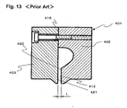
- Figs. 11, 12 and 13 show the transverse sectional views of respectively different publicly known slit dies 201, 301 and 401.
- the slit die 201 comprises a die hopper 205, a right lip 202 and a left lip 203.
- the right lip 202 and the left lip 203 are positioned to face each other with a lip gap 212 formed between them.
- the top face of the right lip 202 and the top face of the left lip 203 respectively contact the bottom face of the die hopper 205, and are respectively attached to the die hopper 205 for integration by means of bolts 206 and 207.
- the lip gap 212 has a lip gap width L.
- This slit die 201 is disclosed in JP 10-264229 A .
- the slit die 201 with this constitution needs such complicated assembling work in which both the lips 202 and 203 must be positioned against the die hopper 205 while the lip gap width L is measured in the longitudinal direction of the lip gap 212 (in the direction perpendicular to the paper surface). This assembling work does not practically allow a lip gap accuracy in the order of sub-microns to be achieved.
- the slit die 301 comprises a right lip 302, a left lip 303 and a shim 304. Both the lips 302 and 303 are combined for integration by a bolt 305 with the shim 304 kept between them.
- a lip gap 312 is formed by the thickness St of the shim 304.
- the lip gap 312 has a lip gap width L.
- This slit die 301 is disclosed in JP 2001-46949 A or JP 2001-191004 A .
- the lip gap width L of the lip gap 312 is equal to the thickness St of the shim 304, irrespectively of the assembling method. Therefore, to achieve a lip gap accuracy in the order of sub-microns, the thin shim 304 having a thickness St of about 0.05 to about 0.7 mm is required to have a thickness accuracy in the order of sub-microns.
- the shim 304 formed with a plate produced from a rolled steel plate has an in-plane thickness irregularity as large as several microns due to rolling irregularity. Furthermore, since it is thin, it is difficult to re-machine it for achieving a higher accuracy. Therefore, either in the case of the slit die 301, a lip gap accuracy in the order of sub-microns cannot be achieved.
- the slit die 401 comprises a right lip 402 and a left lip 403. Both the lips 402 and 403 have a butt interface 415 at their upper portions.
- the inner lip face 420 of the right lip 402 is positioned with a position difference distance L kept from the butt interface 415.
- the inner face 421 of the left lip 403 is in the same plane as that of the butt interface 415 and forms a flat lip. Between the inner lip face 420 of the right lip 402 and the inner face 421 of the left lip 403, a lip gap 412 is formed.
- the lip gap 412 has a lip gap width L equal to the position difference distance L.
- This slit die 401 is disclosed in JP 10-146556 A or JP 10-151395 A .
- the lip gap width L of the lip gap 412 is equal to the position difference distance L established in the lip 402. Therefore, for achieving a lip gap accuracy in the order of sub-microns, it is necessary that the position difference between the butt interface 415 and the inner lip face 420 of the lip 402 is formed at a high finishing accuracy in the order of sub-microns.
- a die coater using any of these slit dies, known is a die coater comprises a table capable of reciprocating and a coating head (slit die) having a downward discharge opening.
- a glass substrate is sucked and held on the table, and subsequently, the glass substrate is moved together with the table right under the coating head, when a coating liquid is discharged from the discharge opening of the coating head, to continuously form a coating film of the coating liquid on the glass substrate.
- This die coater is disclosed in JP 6-339656 A .
- the coating methods at the coating start portion and the coating end portion of each substrate are important for enhancing the thickness accuracy of the coating film on the entire substrate.
- the coating start portion available is a method of controlling the relation between the action of the coating liquid feed pump and the action of the substrate. This method is disclosed in JP 8-229482 A .
- preliminary coating from a die to a roll is performed to form bead of the coating liquid between the die and the roll, and the die is moved together with the bead toward the substrate, to start regular coating on the substrate.
- This method is disclosed in JP 2001-310147 A .
- the clearance between the substrate and the die is controlled in interlock with the discharge of the coating liquid and with the horizontal movement of the die to the substrate. This method is disclosed in JP 2002-113411 A .
- the method in which the regular coating on a substrate is started after preliminary coating from a die to a roll has such disadvantages that (i) extra equipment is needed to raise the cost, (ii) extra action is needed to make the tact longer, not allowing productivity enhancement, (iii) a slight amount of the coating liquid remains at the tip of the die discharge opening after preliminary coating on the roll, and since the remaining amount is not constant, the thickness of the coating film at the coating start portion varies and is not stable, and (iv) the preliminary coating increases the amount of the coating liquid not used for the regular coating, to raise the cost.
- the following causes can be considered: (i) the area at and near the discharge opening of the die is cleaned before coating, to keep the coating start portion 801 always in the same state, and in this case, the coating liquid inside the die near the discharge opening is brought away to form voids in the die, or (ii) within the short time after cleaning of the area at and near the discharge opening of the die till coating, it can happen that the solvent of the coating liquid existing in the area at and near the discharge opening is evaporated to form voids in the die near the discharge opening depending on the evaporated amount, and that as a result, the voids not filled with the coating liquid exist in the die and are transferred as they are onto the coating start portion 801 of the substrate B as the non-coated spots 803.
- An object of the invention is to solve the problems of the prior art.
- the object of the invention is to provide a slit die that allows a lip gap accuracy in the order of sub-microns to be easily achieved.
- the slit die of the invention allows a uniform coating film to be formed with a very high coating thickness accuracy of 3% or less even if no special adjustment is performed after the die has been assembled.
- Another object of the invention is to provide a method and apparatus for producing a substrate with coating films using the slit die.
- the substrate with coating films produced by the invention can be preferably used as a member for a color liquid crystal display, or as a member for a plasma display.
- the invention allows a coating film with a uniform thickness to be easily formed over the entire surface of a substrate without performing preliminary coating irrespectively of the coating liquid used and irrespectively of the coating thickness.
- the invention allows the shortening of tact time and the decrease in the amount of wasted coating liquid and allows the production cost to be reduced in the production of a substrate with coating films.
- one of said positioning blocks is provided at plural positions with an interval kept between them in the longitudinal direction of said lips.
- the maximum height Ry of the surface roughness of said position deciding face of said positioning block is from 0.1S to 1.OS.
- the thicknesses of said first block and said second block in the direction perpendicular to the face forming said lip gap are respectively 30 mm or more; the sectional form of said positioning block in the direction along said position deciding face is quadrangular; the length of said quadrangle in the longitudinal direction of said lips is from 20 mm to 100 mm, while the length in the direction perpendicular to the longitudinal direction is from 20 mm to 100 mm; and the thickness of said positioning block at the region where at least said position deciding face is positioned is 30% or more of the thickness of said second block.
- one of said positioning blocks is provided at plural positions with an interval kept between them in the longitudinal direction of said lips.
- the installation intervals are less than 100 mm.
- said second lip may have a structure similar to that of said first lip.
- the inner face of said first block and the inner face of said second lip are positioned in contact with each other or through a shim, and that said lip gap is formed between the inner face of said second block and the inner face of said second lip.
- the inner face of said second lip facing the inner face of said first block and the inner face of said second lip forming said lip gap may be positioned substantially in the same plane.
- the inner face of said first block facing the inner face of said second lip and the inner face of said second block forming said lip gap may be positioned substantially in the same plane.
- a method for producing a substrate with coating films of the invention by using a slit die of the invention comprises the steps of feeding a coating liquid into said liquid feed passage of said slit die, discharging said coating liquid from said discharge opening through said lip gap, relatively moving at least either a member to be coated, positioned with a clearance formed against said discharge opening or said slit die, and coating said member to be coated, with said coating liquid discharged from said discharge opening, for forming a coating film of said coating liquid on said member to be coated.
- the method for producing a substrate with coating films of the invention it is preferred to comprise a first step of discharging said coating liquid with a certain volume Q1 from said discharge opening of said slit die, a second step of standing by for a certain time period Ts after completion of the first step, a third step of moving said discharge opening relatively to said member to be coated, after completion of the second step, for forming a clearance S1 between them, and a fourth step of discharging said coating liquid from said discharge opening after completion of the third step, while moving said member to be coated, relatively to said slit die, for forming a coating film on said member to be coated.
- the method for producing a substrate with coating films of the invention it is preferred to comprise a first step of moving said discharge opening of said slit die relatively to said member to be coated, kept stationary, for forming a clearance S2 between them, a second step of discharging said coating liquid with a certain volume Q2 from said discharge opening after completion of the first step, a third step of standing by for a certain time period Ts after completion of the second step, and a fourth step of discharging said coating liquid from said discharge opening, after completion of the third step, while moving said member to be coated, relatively to said slit die, for forming a coating film on said member to be coated.
- the size of said first clearance S3 is smaller than the size of said second clearance S4.
- An apparatus for producing a substrate with coating films of the invention comprises the slit die of the invention, a coating liquid feed means engaged with said liquid feed passage of said slit die, a coating liquid discharge means for discharging the coating liquid fed into said liquid feed passage, from said discharge opening through said lip gap, and a coating film forming means for relatively moving at least either a member to be coated, positioned with a clearance formed against said discharge opening, or said slit die, to coat said member to be coated, with said coating liquid discharged from said discharge opening, for forming a coating film of said coating liquid on said member to be coated.
- a preferred embodiment of the apparatus for producing a substrate with coating films of the invention comprises a means for discharging a certain amount of said coating liquid from said discharge opening of said slit die, a means for letting a certain standby time period to elapse after discharging said certain amount of said coating liquid, and a coating film forming means for relatively moving at least either a member to be coated, positioned with a clearance formed against said discharge opening, or said slit die after lapse of said standby time period, while coating said member to be coated, with said coating liquid discharged from said discharge opening, to form a coating film of said coating liquid on said member to be coated.
- a slit die 1 of the invention comprises a first lip 3 and a second lip 2.
- the first lip 3 and the second lip 2 are integrated by a lip fastening element with inner faces 15a and 15b of the first lip 3 and inner faces 17a and 17b of the second lip 2 facing each other, in such a manner that they can be separated.
- six assembling bolts 7 disposed with intervals kept between them are used as the lip fastening element as shown in Fig. 1 .
- the inner faces 15a and 15b and the inner faces 17a and 17b facing each other are positioned to be partially apart from each other, to thereby form a liquid feed passage (manifold) 12 and a lip gap 13 extending in the longitudinal direction of the lips 2 and 3.
- the bottom end of the lip gap 13 forms a discharge opening 14 toward outside. Both side ends of the lip gap 13 in the longitudinal direction are closed from outside by sealing plates 6a and 6b.
- the top end of the lip gap 13 communicates with the liquid feed passage (manifold) 12.
- the liquid feed passage (manifold) 12 has a coating liquid feed port 11 that is connected through a feed pipe (not shown in the drawing) with a coating liquid feed means (not shown in the drawing).
- the coating liquid fed from the coating liquid feed means flows from the coating liquid feed port 11 into the manifold 12 that guides the flow of the coating liquid toward both sides with the coating liquid feed port 11 as the center. Then, the coating liquid flows into the lip gap 13 and is discharged from the discharge opening 14.
- the first lip 3 comprises a first block 4 and a second block 5.
- the length of the bottom face of the first block 4 in the longitudinal direction is equal to the length of the top face of the second block 5 in the longitudinal direction.
- the inner face 17a of the second lip 2 and the inner face 15a of the first block 4 contact each other.
- the bottom face of the first block 4 and the top face of the second block 5 contact each other.
- the first block 4 and the second block 5 are engaged with each other by a block engaging element capable of adjusting their relative position in the direction perpendicular to the face 15b forming the gap 13, of the first lip 3 (the inner face of the second block).
- a block engaging element capable of adjusting their relative position in the direction perpendicular to the face 15b forming the gap 13, of the first lip 3 (the inner face of the second block).
- bolts 8 and nuts 9 are used as the block engaging element.
- first block 4 and the second block 5 After the relative position between the first block 4 and the second block 5 has been adjusted, they are fastened and integrated by a block fastening element.
- a block fastening element As the block fastening elements, bolts 8 and nuts 9 are used.
- the bolts 8 and the nuts 9 function as the block engaging elements as well as the block fastening elements.
- the block engaging element and the block fastening element can be constituted by respectively different members, so that the respective functions can work separately.
- a positioning element for deciding the relative position between the first block 4 and the second block 5 are engaged with an outer face 16a of the first block 4 and an outer face 16b of the second block 5 respectively on the side opposite to the inner face 15a of the first lip 3.
- five stepped blocks 10 disposed with intervals kept between them are used as the positioning element.
- An inner face 10a of the upper portion of the stepped block 10 contacts the outer face 16a of the first block 4, and an inner face 10b of the lower portion of the stepped block 10 contact the outer face 16b of the second block 5.
- the inner face 10a and the inner face 10b form a position deciding face.
- a positioning element fixing element is provided for fixing the positioning element (stepped blocks 10) to the first lip 3 comprising the first block 4 and the second block 5.
- the positioning element (stepped block 10) fixing element bolts 20 are used as the positioning element (stepped block 10) fixing element.
- the inner face 17a of the second lip 2 facing the inner face 15a of the first block 4 and the inner face 17b of the second lip 2 forming the lip gap 13 are positioned in substantially the same plane.
- the positioning element (stepped blocks 10) and the positioning element fixing element (bolts 20) are used to adjust the lip gap width Lg of the lip gap 13 for making it uniform in the longitudinal direction of the lip gap 13.
- the difference with distances h is called a position difference h
- the sizes of the position difference h are called a position difference distance h.
- the position difference H with position difference distance H is formed by pressing the five stepped blocks 10 with position differences h to the outer face 16a of the first block 4 and the outer face 16b of the second block 5.
- the number and installation intervals of the stepped blocks 10 are not especially limited, but if the slit die 1 is long, it is preferred to install at least two or more, preferably five or more stepped blocks 10 in the longitudinal direction. It is desirable that the installation intervals are 100 mm or less, for forming uniform position difference distance H in the longitudinal direction of the slit die 1.
- the lip gap 13 with gap width Lg equal to the position difference distance H between the inner face 15a of the first block 4 and the inner face 15b of the second block 5 is formed.
- the lip gap 13 serves to give a flow resistance to the coating liquid and to discharge the coating liquid from the discharge opening 14 with a uniform distribution.
- the gap width Lg of the lip gap 13 is from 30 ⁇ m to 1,000 ⁇ m. A more preferred range is from 50 ⁇ m to 600 ⁇ m.
- the length Ld of the lip gap 13 in the direction of discharging the coating liquid is from 3 mm to 100 mm. A more preferred range is from 5 mm to 70 mm.
- the length of the discharge opening 14 in the longitudinal direction as the discharge width of the coating liquid is decided by the installation interval Lw of the two sealing plates 6a and 6b.
- the material and form of the sealing plates 6a and 6b are not especially limited, if they are not affected by the solvent and other ingredients contained in the coating liquid and allow sealing to prevent the leak of the coating liquid.
- Metallic plates such as stainless steel plates with a thickness equal to or slightly smaller than the gap width Lg of the lip gap 13 or on the contrary, elastic members, for example, resin sheets such as polyethylene terephthalate sheets with a thickness slightly larger than the gap width Lg can be suitably used.
- the first block 4 and the second block 5 are overlaid with one on the other and temporarily set by means of the bolts 8 and the nuts 9, and in this state, they are machined simultaneously to ensure that their thicknesses Lt in the direction perpendicular to the inner faces 15a and 15b become equal to each other.
- all the stepped blocks 10 are attached to the outer face 16a of the first block 4 by means of the bolts 20.
- the second block 5 is slid in the direction perpendicular to the inner face 15b, causing the outer face 16b of the second block 5 to contact the inner faces 10b of the lower portions of the stepped blocks 10. Then, the stepped blocks 10 are fixed to the second block 5 using the bolts 20, to complete the adjustment of the relative position between the first block 4 and the second block 5.
- the position difference H with position difference distance H equal to the position difference distances h of the stepped blocks 10 is uniformly formed between the blocks 4 and 5 in the longitudinal direction.
- the faces in contact with the first block 4 and the second block 5, namely, the inner faces 10a of the upper portions and the inner faces 10b of the lower portions of the stepped blocks 10 have their surface roughness kept in a range from 0. 1S to 1.0S as the maximum height (Ry) defined in JIS B 0031 (1994).
- the first block 4 and the second block 5 have high rigidity.
- the thicknesses Lt of the respective blocks are 30 mm or more. In the case where the respective thicknesses Lt are less than 30 mm, the respective blocks 4 and 5 are likely to be warped in the sections free from the stepped blocks 10 in the longitudinal direction, making the fine adjustment of the position difference distance H difficult.
- each stepped block corresponding to the longitudinal direction of the slip die 1 is in a range from 20 mm to 100 mm, and that the height in the direction perpendicular to it is in a range from 20 mm to 100 mm. If the form of the stepped blocks 10 is smaller than the lower limits of these ranges, the correction force necessary for the free fine adjustment of the position difference distance H cannot be sufficiently exhibited. On the contrary, if the form is larger than the upper limits of these ranges, it is difficult to finely change the position difference distances h by a working means such as lapping or grinding.
- the stepped blocks 10 must have the rigidity necessary for the fine adjustment of the position difference distance H.
- the thickness of each stepped block 10 at the thinnest portion corresponds to 30% or more of the thickness Lt of the second block 5.
- the deviation of the position difference distances h among the plural stepped blocks 10 installed in the longitudinal direction is 1 ⁇ m or less. More preferred is 0.5 ⁇ m or less.
- the inner faces 17a and 17b of the second lip 2 are finished to be 5 ⁇ m or less in flatness. It is more preferred that the respective faces are finished to be 2 ⁇ m or less.
- the flatness in this case is defined in "Definitions and Indications of Geometric Deviations" of JIS B 0621 (1984).
- the rigidity of the first lip 3 is the same as that of the second lip 2.
- the thickness of the second lip 2 is kept equal to the thickness Lt of the first block 4 and the second block 5.
- the slit die 1 shown in this embodiment has a constitution as described above, a lip gap accuracy in the order of sub-microns can be easily achieved even though the slit die is long, namely, even though the slit die is used to form a coating film with a large area. For this reason, if the slit die 1 is assembled with the stepped blocks 10 fixed to the first lip 3, a coating film with a very high coating thickness accuracy of 3% or less can be formed even without performing any special adjustment.
- the slit die 1 can be suitably used.
- the thickness irregularity of the coating film due to the factor can be improved.
- the position difference distances h of the stepped blocks 10 can be changed to change the gap width Lg of the lip gap 13, or the respective position difference distances h of plural stepped blocks 10 installed in the longitudinal direction can be made different from each other to form a lip gap 13 with a distribution corresponding to a given thickness profile of a coating film.
- the positioning elements for positioning the first block 4 and the second block 5 by sliding them relatively to each other are not limited to the stepped blocks 10. Examples of the positioning elements other than the stepped blocks are explained below.
- Fig. 4 shows another embodiment of the slit die of the invention.
- a slit die 101 comprises a first lip 3, a second lip 2, a first block 4 and a second block 5 constituting the first lip 3, and bolts 8 and nuts 9 for engaging and fastening the first block 4 with and to the second block 5.
- the slit die 101 has a lip gap 13, a discharge opening 14 and a manifold 12.
- the inner face 17a of the second lip 2 facing the inner face 15a of the first block 4 and the inner face 17b of the second lip 2 forming the gap 13 are positioned substantially in the same plane.
- the slit die 101 has positioning elements, each comprising a flat block 110 and a shim 114 (position definition assisting means), instead of the stepped blocks 10 in the embodiment shown in Fig. 2 .
- the inner faces 110a of the flat blocks 110 respectively have a single flat face.
- the inner faces 110a are kept in contact with the outer face 16b of the second block 5.
- the shims 114 intervene in the gaps formed by the position differences between the outer face 16a of the first block 4 and the inner faces 110a of the flat blocks 110.
- the shims 114 are fitted in the gaps when the flat blocks 110 and the second block 4 are fixed using the bolts 20 of the flat blocks 110.
- the thicknesses of the shims 114 are adjusted to be equal to the gap width Lg of the lip gap 13.
- the position difference distance H between the first block 4 and the second block 5 can be finely adjusted by finely adjusting the surface roughness values of the inner faces 110a of the flat blocks 110 or finely adjusting the thicknesses of the shims 114.
- the gap width Lg of the lip gap 13 of the slit die 101 can be adjusted uniformly in the longitudinal direction of the lip gap 13 by the positioning elements and the positioning element fixing elements comprising the flat blocks 110, shims 114 and bolts 20.
- Fig. 5 shows a further other embodiment of the slit die of the invention.
- a slit die 102 comprises a first lip 3, a second lip 2, a first block 4 and a second block 5 constituting the first lip 3, and bolts 8 and nuts 9 used for engaging and fastening the first block 4 with and to the second block 5.
- the slit die 102 has a lip gap 13, a discharge opening 14 and a manifold 12.
- the inner face 17a of the second lip 2 facing the inner face 15a of the first block 4 and the inner face 17b of the second lip 2 forming the lip gap 13 are positioned substantially in the same plane.
- the slit die 102 has positioning elements, each comprising a flat block 110 and an expansion means 112 (position definition assisting means) instead of the stepped blocks 10 shown in Fig. 2 .
- the inner faces 110a of the flat blocks 110 respectively have a single flat face.
- the inner faces 110a are kept in contact with the outer face 16b of the second block 5.
- the expansion means 112 intervene in the gaps formed by the position differences between the outer face 16a of the first block 4 and the inner faces 110a of the flat blocks 110.
- the expansion means 112 are, for example, micrometer heads or linear actuators.
- the expansion means 112 are fixed to the tops of the flat blocks 110. Expansion members 112a of the expansion means 112 are projected from the inner faces 110a of the flat blocks 110 toward the first block 4, and their tips are pressed against the outer face 16a of the first block. The projecting lengths of the expansion members 112a from the inner faces 110a of the flat blocks 110 to the outer face 16a of the first block 4 are adjusted to be equal to the gap width Lg of the lip gap 13.
- the position difference distance H between the first block 4 and the second block 5 can be finely adjusted by finely adjusting the projecting lengths of the expansion members 112a of the expansion means 112. With this fine adjustment, the gap width Lg of the lip gap 13 of the slit die 102 can be adjusted uniformly in the longitudinal direction of the lip gap 13 by the positioning elements and the positioning element fixing elements comprising the flat blocks 110, expansion means 112 and bolts 20.
- the method for measuring the position difference distance H is not especially limited if measurement can be performed at a necessary resolution and accuracy.
- two linear gauges are pressed against at right angles to a uniform surface such as a precision surface plate and set at zero, and one of them is pressed against at right angles to the inner face 15a of the first block 4 while the other linear gauge is pressed against at right angles to the inner face 15b of the second block 5.
- the value indicated by the other linear gauge is read. This method is preferred since measurement can be performed simply at high accuracy.
- the lip gap accuracy is defined as the maximum deviation of the values obtained by measuring the gap width (for example, the gap width Lg in Fig. 2 ) of the lip gap at many points in the longitudinal direction of the lip gap.
- the measuring method it is preferred that an optical microscope or the like is used to measure the gap width of the discharge opening (for example, the discharge opening 14 in Fig. 2 ) magnified 450 fold to 2,000 fold, as the gap width of the lip gap.
- the first block 4 and the second block 5 respectively having the same thickness Lt are used for setting position difference H in the second lip 3.
- the method for establishing the position difference H is not limited to it.
- Fig. 6 shows another method for establishing the position difference H.
- a slit die 103 of the invention comprises a first lip 3, a second lip 2, a first block 4a and a second block 5a constituting the first lip 3, and bolts 8 and nuts 9 for engaging and fastening the first block 4a with and to the second block 5a.
- the slit die 103 has a lip gap, 13, a discharge opening 14 and a manifold 12.
- the inner face 17a of the second lip 2 facing the inner face 15a of the first block 4a and the inner face 17b of the second lip 2 forming the lip gap 13 are positioned substantially in the same plane.
- the first block 4a and the second block 5a in the slit die 103 are different in the thickness in the direction perpendicular to the inner face 15b of the second block 5a forming the lip gap 13.
- the slit die 103 is different from the slit dies 1, 101 and 102 shown in Figs. 2 , 4 and 5 .
- the first block 4a has thickness Lta and the second block 5a has thickness Ltb. Owing to the difference between thickness Lta and thickness Ltb, a position difference H1 is formed between the inner face 15a of the first block 4a and the inner face 15b of the second block 5a.
- Flat blocks 111 as positioning elements are fixed to the outer face 16a of the first block 4a and the outer face 16b of the second block 5a by means of bolts 20 provided as fixing elements.
- the inner faces 111a of the flat blocks 111 are kept in contact with the outer face 16a of the first block 4a and the outer face 16b of the second block 5a.
- the lip gap 13 having gap width Lg equal to the position difference distance H1 between the inner face 15a of the first block 4a and the inner face 15b of the second block 5a is formed.
- the number of position differences H (H1) forming the lip gap 13 with gap width Lg is one in the above-mentioned embodiments, but the number is not limited to one. Three or more blocks can be overlaid to form two or more position differences in the first lip 3.
- first lip 3 comprises two blocks, namely, the first block 4 (4a) and the second block 5 (5a) has been explained, but the invention is not limited to this mode.
- a mode in which the first lip 3 and the second lip 2 respectively comprises vertically stacked plural blocks adjustable in their relative positions can also be used.
- the slit die of the invention can also be applied to a slit die for simultaneously forming plural coating films on a member to be coated, namely, to a slit die having two or more lip gaps formed by three or more lips for simultaneous multi-layer coating.
- the method for forming the lip gap 13 is not limited to a mode in which the position difference formed between plural blocks is used to form the lip gap.
- Fig. 7 shows another example for forming the position difference.
- a slit die 104 of the invention comprises a first lip 3, a second lip 2, a first block 4 and a second block 5 constituting the first lip 3, and bolts 8 and nuts 9 for engaging and fastening the first block 4 with and to the second block 5.
- the slit die 104 has a lip gap 13, a discharge opening 14 and a manifold 12.
- the slit die 104 has flat blocks 111 as positioning elements.
- the inner faces 111a of the flat blocks 111 respectively have a single flat face.
- the inner faces 111a are kept in contact with the outer face 16a of the first block 4 and the outer face 16b of the second block 5.
- the inner face 17a of the second lip 2 facing the inner face 15a of the first block 4 and the inner face 17b of the second lip 2 forming the lip gap 13 are positioned substantially in the same plane.
- the slit die 104 is different from the embodiments shown in Figs. 2 , 4 , 5 and 6 .
- the slit die 104 has a gap between the inner face 17a of the second lip 2 and the inner face 15a of the first block 4.
- the gap is filled with a shim 113.
- Fig. 8 shows a further other embodiment of the slit die of the invention.
- the inner face 17a of the second lip 2 is projected toward the inner face 15a of the first block 4 by a distance corresponding to the thickness of the shim 113 in the slit die 104 shown in Fig. 7 , to keep the inner face 17a and the inner face 15a in contact with each other, to thereby form position difference H3.
- the slit die 105 is the same as the slit die 104 of Fig. 7 .
- the essential structure of the slit die of an embodiment of the invention is such that a pair of lips combined can form a lip gap, that at least one of the lips comprises at least two independent blocks, and that the positioning elements for deciding the relative position between the blocks and the elements for fixing the positioning elements are provided for the blocks, for allowing the gap width of the lip gap to be corrected in the longitudinal direction of the lip gap. That is, if this structure is satisfied, individual components and their combination can be arbitrary.
- the lip gap accuracy in the order of sub-microns can be achieved by establishing fine position differences among the flat blocks 111, for the relative position between the first block 4 and the second block 5 constituting the first lip 3, in response to the desired lip gap accuracy.
- the manifold 12 in the slit die 1 can also be installed in the first lip 3, not in the second lip 2, or in each of the first lip 3 and the second lip 2.
- the front form of the manifold 12 can be T shape extended on both sides in the longitudinal direction with the coating liquid feed port 11 as the center as shown in Fig. 1 , or a coat hanger shape inclined on both sides in the longitudinal direction with the coating liquid feed port 11 as the center.
- plural manifolds can also be installed in steps in the coating liquid discharge direction.
- the manifold 12 can also be provided through both the ends in the longitudinal direction of the lips. In this case, side plates installed at both the ends in the longitudinal direction of the lips are used to decide the coating liquid discharge width and to seal the liquid leak.
- the coating liquid feed means not shown in the drawings can be any publicly known means.
- Examples of the coating liquid feed means include a gear pump, Moineau pump, diaphragm pump and syringe pump.
- publicly known filters and valves can be installed as required.
- the material of the lips is not especially limited.
- the material include cemented carbide, ceramic, stainless steel or any of these materials surface-treated.
- Stainless steel is preferred as the material in view of chemicals resistance and low price.
- the length LA of the tip 18 of the second lip 2 and the length LB of the tip 19 of the first lip 3 respectively shown in Fig. 2 can be set as desired in response to the direction in which the coating film is formed.
- the length LA of the tip 18 of the second lip 2 is preferably from 0.1 mm to 15 mm, more preferably from 0.5 mm to 5 mm
- the length LB of the tip 19 of the first lip 3 is preferably from 0.03 mm to 2 mm, more preferably from 0.05 mm to 1 mm
- the length LB of the tip 19 of the first lip 3 is shorter than the length LA of the tip 18 of the second lip 2.
- the straightness of the tip 18 of the second lip 2 and of the tip 19 of the first lip 3 in the longitudinal direction namely, the macroscopic magnitude of waviness in the longitudinal direction is 10 ⁇ m or less. More preferred is 5 ⁇ m or less.
- the surface roughness of the wetted face as maximum height (Ry) is 0.4S or less. More preferred is 0.2S or less. It is further preferred that the tip 18 of the second lip 2 and the tip 19 of the first lip 3 are finished to be 0.1S or less, since the coating quality can be kept good.
- Fig. 9 is a schematic perspective view showing a die coater using the slit die of the invention for carrying out the method for producing a substrate with coating films of the invention.
- Fig. 10 is a schematic constitutional diagram showing the die coater of Fig. 9 including the coating liquid feed system.
- Fig. 9 shows a die coater 21 for coating a unit substrate such as a glass substrate (member to be coated) with a coating liquid for forming a coating film.
- the die coater 21 has a base 22. On the base 22, a pair of guide groove rails 24 is installed, and a stage 26 is arranged on the guide groove rails 24. The top face of the stage 26 is formed as a suction face. The stage 26 can be reciprocated on the guide groove rails 24 by means of a pair of slide legs 28 in the horizontal direction.
- a casing 32 extending along the guide groove rails 24 is disposed, and the casing 32 contains a feed mechanism.
- the feed mechanism has a feed screw 34 composed of a ball screw as shown in Fig. 10 .
- the feed screw 34 is engaged with a nut-like portion of a connector 36 having the nut-like portion fixed under the stage 26, and extends through the connector 36.
- Both the ends of the feed screw 34 are supported by bearings not shown in the drawing in such a manner that it can be revolved.
- One of the ends is connected with an AC servo motor 38 .
- an opening to allow the movement of the connector 36 is formed, though it is not shown in the drawing.
- the stage 26 can be reciprocated, but instead of this method, the slit die 1 can also be reciprocated relatively to the stage 26. It is only required that at least either the stage 26 or the slit die 1 can be reciprocated.
- a reverse L-shaped sensor prop 40 is disposed on one side.
- the tip of the sensor prop 40 extends to above one of the guide groove rails 24, and a motor-operated lift actuator 41 is installed there.
- a thickness sensor 42 is installed to face downward.
- the thickness sensor 42 can be a laser displacement meter, ultrasonic thickness gauge or the like. Above all, a sensor using a laser is preferred.
- a die prop 44 reverse L-shaped like the sensor prop 40 is disposed at a position on the more center side of the base 22 than the sensor prop 40.
- the tip of the die prop 44 is positioned above the intermediate position between the pair of guide groove rails 24, namely, above the reciprocation route of the stage 26.
- a lift mechanism 46 is installed at the tip of the die prop 44.
- the lift mechanism 46 has a lift bracket.
- the lift bracket is attached to a pair of guide rods so that it can be raised and lowered. Between the guide rods, a feed screw composed of a ball screw is disposed, and the feed screw is screwed into a nut portion of the lift bracket and extends through the nut portion.
- the top end of the feed screw is connected with an AC servo motor 50 that is installed on the top face of a casing 48. Meanwhile, said guide rods and feed screw are accommodated in the casing 48 and supported through bearings in such a manner that they can be revolved.
- a die holder 52 comprising a flat plate and lateral plates provided at both the ends of the flat plate is installed to the lift bracket in such a manner that it can be revolved around a support shaft (not shown in the drawing) within a vertical plane.
- the die holder 52 extends horizontally across the pair of guide groove rails 24 above said guide groove rails.
- a horizontal bar 56 is fixed to the lift bracket at a position above the die holder 52, and the horizontal bar 56 extends along the die holder 52.
- Motor-operated control actuators 58 are installed at both the ends of the horizontal bar 56.
- the control actuators 58 have expansible rods projected from the bottom face of the horizontal bar 56, and the bottom ends of the expansible rods are kept in contact with both the ends of the die holder 52.
- the slit die 1 of the invention is installed inside the die holder 52.
- a feed hose 62 for a coating liquid 90 extends, and the tip of the feed hose 62 is connected with a feed port of an electromagnetic selector valve 66 of a syringe pump 64.
- an electromagnetic selector valve 66 of a syringe pump 64.
- a suction hose 68 extends, and the tip of the suction hose 68 is inserted into a tank 70 storing the coating liquid 90.
- the pump proper 72 of the syringe pump 64 can be selectively connected with either the feed hose 62 or the suction hose 68 by the selection action of the electromagnetic selector valve 66.
- the electromagnetic selector valve 66 and the pump proper 72 are electrically connected with a computer 74, so that they can receive control signals from the computer 74, for being controlled in their actions.
- the computer 74 is also electrically connected with the lift actuator 41 and the thickness sensor 42.
- the computer 74 is also electrically connected with a sequencer 76.
- the sequencer 76 is provided for sequence-controlling the action of the AC servo motor 38 of the feed screw 34 on the stage 26 side and the action of the AC servo motor 50 of the lift mechanism 46.
- the signals indicating the action states of the AC servo motors 38 and 50, the signals from the position sensors 78 detecting the moving position of the stage 26, the signal from the sensor (not shown in the drawing) detecting the action state of the slit die 1, and the like are applied to the sequencer 76.
- signals showing the sequence actions are delivered to the computer 74.
- the AC servo motor 38 can contain an encoder, so that the sequencer 76 can detect the position of the stage 26 based on the pulse signals delivered from the encoder.
- the control by the computer 74 can also be incorporated into the sequencer 76.
- the die coater 21 has a loader for feeding a unit substrate as the member to be coated, for example, a glass substrate A for a color filter onto the stage 26 and an unloader for removing the glass substrate A from the stage 26.
- a loader for feeding a unit substrate as the member to be coated, for example, a glass substrate A for a color filter onto the stage 26 and an unloader for removing the glass substrate A from the stage 26.
- the loader and the unloader for example, cylindrical-coordinate industrial robots can be used as main components of them.
- the slit die 1 extends horizontally in the direction perpendicular to the reciprocating direction of the stage 26, namely, in the width direction of the stage 26, and is supported by the die holder 52.
- the slit die 1 can be horizontally adjusted by expanding or contracting the expansion rods of the control actuators 58 provided at both the ends of the horizontal bar 56 and revolving the die holder 52 around its support shaft.
- Figs. 9 and 10 at first, the respective working parts of the die coater 21 are returned to their home positions.
- the stage 26 is positioned below the thickness sensor 42.
- the route from the tank 70 through the suction hose 68 and the feed hose 62 to the manifold 12 and the lip gap 13 in the slit die 1 is filled with the coating liquid 90.
- the electromagnetic selector valve 66 of the syringe pump 64 is actuated so that the pump proper 72 can be connected with the suction hose 68. With this action, the coating liquid 90 in the tank 70 is sucked into the pump proper 72 through the suction hose 68. If a predetermined amount of the coating liquid 90 is sucked into the syringe pump 64, the electromagnetic selector valve 66 of the syringe pump 64 is actuated so that the pump proper 72 can be connected with the feed hose 62.
- the glass substrate A has a width substantially equal to or wider than the discharge width of the discharge opening 14 in the slit die 1, namely, the distance Lw between the sealing plates 6a and 6b.
- the thickness sensor 42 is lowered to a predetermined position, and the thickness of the glass substrate A is measured by the thickness sensor 42. After completion of measurement, the thickness sensor 42 is raised to the original position.
- the stage 26 is moved toward the slit die 1 and is stopped immediately before the slit die 1. Subsequently, the slit die 1 is lowered, and a predetermined clearance, for example, a clearance of 100 ⁇ m is secured between the bottom face of the slit die 1 and the top face of the glass substrate A.
- a predetermined clearance for example, a clearance of 100 ⁇ m is secured between the bottom face of the slit die 1 and the top face of the glass substrate A.
- the thickness of the glass substrate A measured by the thickness sensor 42 is taken into account, and based on the output signal from the distance sensor (not shown in the drawing) used for measuring the distance between the stage 26 and the slit die 1, the descending position of the slit die 1 is decided and accurately set.
- the stage 26 is moved further, and at the time point when the start line at which the formation of a coating film should be started on the top face of the glass substrate A is positioned right under the discharge opening 14 of the slit die 1, the stage 26 is once stopped.
- the syringe pump 64 is made to start discharging the coating liquid 90, to feed the coating liquid 90 toward the slit die 1.
- the coating liquid 90 is discharged from the discharge opening 14 of the slit die 1 onto the glass substrate A.
- the gap of the discharge opening 14 is constant in the longitudinal direction of the slit die 1, namely, in the direction perpendicular to the reciprocating direction of the stage 26, the coating liquid 90 is discharged uniformly along the start line of the glass substrate A from the discharge opening 14.
- a liquid bank C of the coating liquid called bead is formed along the start line between the slit die 1 and the glass substrate A.
- the stage 26 is made to progress in the reciprocating direction at a certain speed, to continuously form a coating film D of the coating liquid 90 on the top face of the glass substrate A as shown in Fig. 10 .
- the coating liquid 90 may also be discharged from the discharge opening 14 at the timing at which the start line of the glass substrate A passes under the discharge opening 14 of the slit die 1, without once stopping the movement of the stage 26.
- the finish line at which the formation of the coating film D on the glass substrate A should be finished reaches the position immediately before the discharge opening 14 of the slit die 1.
- the discharge action of the syringe pump 64 is stopped. Even if the discharge of the coating liquid 90 from the discharge opening 14 of the slit die 1 is stopped in this way, the formation of the coating film D is continued till the finish line while the coating liquid of the liquid bank C on the glass substrate A is consumed.
- the discharge action of the syringe pump 64 can also be stopped at the time point when the finish line on the glass substrate A has passed the discharge opening 14 of the slit die 1.
- the syringe pump 64 is made to act for sucking slightly, and as a result, the coating liquid 90 in the lip gap 13 of the slit die 1 is sucked toward the manifold 12. At the same time, the slit die 1 is raised to the original position, to finish the application of the coating liquid 90 by the slit die 1.
- the syringe pump 64 is made to act for discharge the same amount as that sucked, so that no air should remain in the lip gap 13 of the slit die 1. Subsequently, the electromagnetic selector valve 66 of the syringe pump 64 is actuated so that the pump proper 72 can be connected with the suction hose 68, and the pump proper 72 is made to act for sucking the coating liquid in the tank 70 through the suction hose 68. If a predetermined amount of the coating liquid is sucked into the syringe pump 64, the electromagnetic selector valve 66 of the syringe pump 64 is actuated so that the pump proper 72 can be connected with the feed hose 62. Subsequently, while the slit die 1 is kept at its high position, the coating liquid 90 deposited on the bottom end of the slit die 1 is wiped off by a cleaner (not shown in the drawing) .
- the forward movement of the stage 26 is continued even if the application of the coating liquid 90 is finished, and the time point when the stage 26 has reached the ends of the guide groove rails 24, the forward movement is stopped.
- the glass substrate A with the coating film D formed is liberated from suction and taken away from the stage 26 by the unloader.
- the stage 26 is moved backward and returned to the initial position shown in Fig. 9 , to complete a series of coating process.
- the stage 26 stands by till it is loaded with a new glass substrate.
- the coating liquid 90 used for forming the coating film is not especially limited if it is a flowable liquid.
- the coating liquid include a coating liquid for coloration, a coating liquid for resist, a coating liquid for surface protection, a coating liquid for antistatic treatment, a coating liquid for lubrication, etc.
- Coating liquids obtained by dissolving or dispersing a polymeric material or an inorganic material such as glass or metal into water or an organic solvent are often used.
- the viscosity of the coating liquid 90 used is from 1 mPa ⁇ s to 100,000 mPa ⁇ s. A more preferred range is from 5 mPa ⁇ s to 50,000 mPa ⁇ s.
- a Newtonian coating liquid is preferred in view of coating property, but a thixotropic coating liquid can also be used.
- a metallic sheet such as aluminum sheet, ceramic sheet, a silicone wafer or the like can also be used in addition to a glass substrate.
- the clearance is from 20 ⁇ m to 500 ⁇ m.
- a more preferred range is from 50 ⁇ m to 400 ⁇ m.
- the coating speed is from 0.1 m/min to 50 m/min.
- a more preferred range is from 0.5 m/min to 10 m/min.
- the lip gap is from 30 ⁇ m to 1, 000 ⁇ m.
- a more preferred range is from 50 ⁇ m to 600 ⁇ m.
- the coating thickness is from 3 ⁇ m to 500 ⁇ m.
- a more preferred range is from 5 ⁇ m to 300 ⁇ m.
- the method for producing a substrate with coating films of the invention can be preferably used for producing a member for a display.
- the member for a display include a color filter used for a liquid crystal display, a back plate and a front plate of a plasma display, etc.
- a unit substrate such as a glass substrate
- a long web a long member to be coated
- a film, metallic sheet, metallic foil or paper can be realized by bringing the slit die 1 of the invention closer to the web at a portion where it is supported and carried by means of a roll, and discharging the coating liquid from the discharge opening 14 of the slit die 1.
- Fig. 14 is a schematic front sectional view showing an example of the coater used for carrying out the method for producing a substrate with coating films of the invention.
- Fig. 15 is a time chart showing the action states of respective working parts when the coater of Fig. 14 is used for coating.
- Fig. 16A and Fig. 16B are plan views for explaining the states where a coating film is formed on a substrate.
- Fig. 17 is a schematic perspective view for explaining the state where bead is formed between a slit die and a substrate.
- a coater (a die coater) 501 has a base 502, and a pair of guide rails 504 is installed on the base 502.
- a stage 506 is arranged, and the stage 506 can be driven by a linear motor not shown in the drawing, for being reciprocated in the arrow X directions.
- the top face of the stage 506 is a vacuum suction face with suction holes, so that the substrate B as the member to be coated can be sucked and held.
- a gate-shaped prop 510 is installed at the center of the base 502.
- vertical lift units 570 are provided on both sides of the prop 510, and the slit die 520 of the invention used for coating is installed in the vertical lift units 570.
- the slit die 520 is composed in such a manner that a front lip 522 and a rear lip 524 respectively extending in the direction perpendicular to the arrow X directions, namely, in the direction perpendicular to the paper surface are overlaid in X directions and integrally combined using plural connection bolts not shown in the drawing.
- the front lip 522 is composed in such a manner that two blocks different in thickness are overlaid with one on the other, with their outer faces positioned in the horizontal direction (X directions) by a positioning block 532.
- the positioning block 532 is fixed to the two blocks constituting the front lip 522 using elements (not shown in the drawing) for fixing the positioning block 532.
- a manifold 526 is formed, and the manifold 526 also extends in the longitudinal direction of the die 520 (horizontal direction perpendicular to the X directions).
- a lip gap (slit) 528 is formed to communicate with the manifold 526.
- the slit 528 also extends in the longitudinal direction of the die 520, and the bottom end opens at the discharge opening face 536 corresponding to the lowest end face of the die 520, to form a discharge opening 534.
- the gap width (slit width) (measured in the X directions) of the slit 528 is equal to the difference between the thicknesses of the two blocks constituting the front lip 522.
- the vertical lift units 570 for lifting and lowering the die 520 comprises a suspending/holding base 580 for suspending and holding the die 520, a pair of lift bases 578 for lifting and lowering the suspending/holding base 580, guides 574 for guiding the lift bases 578 in the vertical direction, and ball screws 576 for converting the revolving motion of motors 572 into the straight motion of the lift bases 578.
- the vertical lift units 570 are provided as a pair for supporting both the ends of the die 520 in the longitudinal direction and can be raised and lowered respectively independently. So, the inclination angle of the die 520 in reference to the level in the longitudinal direction can be set as desired. In this constitution, the discharge opening face 536 of the die 520 and the substrate B can be kept virtually parallel to each other in the longitudinal direction of the die 520. Furthermore, the vertical lift units 570 can be used to set a clearance with a desired size between the substrate B on the stage 506 and the discharge opening face 536 of the die 520
- a wipe-off unit 590 is placed on the guide rails 504 in such a manner that it can be moved in the X directions.
- a wipe-off head 592 shaped to allow engagement with the area at and near the discharge opening 534 of the die 520 is installed on a slider 596 through a bracket 594.
- the slider 596 can be moved by a drive unit 598 in the longitudinal direction of the die 520, namely, in the horizontal direction perpendicular to the X directions.
- the drive unit 598 and a tray 600 are fixed on a carriage 602.
- the carriage 602 is placed on the guide rails 504 and can be reciprocated in the X directions by a linear motor not shown in the drawing, being guided by the guide rails 504. So, the wipe-off unit 590 as a whole can be reciprocated in the X directions.
- the unit 590 as a whole is moved in the X directions, and the die 520 is lowered and engaged with the wipe-off head 592. If the drive unit 598 is driven for allowing the wipe-off head 592 to slide in the longitudinal direction of the die 520, the coating liquid 566 and other contaminant remaining near the discharge opening of the die 520 can be removed for cleaning.
- the removed coating liquid 566 and other contaminant are collected by the tray 600.
- the tray 600 is connected with a discharge line not shown in the drawing, and the liquid such as the coating liquid 566 and other contaminant collected inside can be discharged and collected.
- the tray 600 can also be used to collect the coating liquid 566 discharged from the die 520 by air venting or the like.
- the wipe-off head 592 is formed of an elastic material such as rubber or synthetic resin so that it can be uniformly engaged with the die 520.
- a thickness sensor 620 for measuring the thickness of the substrate B is installed in a support base 622. It is preferred that the thickness sensor 620 uses a laser. If the thickness sensor 620 is used to measure the thickness of the substrate B, the clearance as the gap between the discharge opening face 536 of the die 520 and the substrate B can be always kept constant irrespectively of the thickness of the substrate B.
- the upstream side of the manifold 526 of the die 520 is always connected through an internal passage (not shown in the drawing) with a feed hose 560 communicating with a coating liquid feeder 540.
- the coating liquid can be fed to the manifold 526 from the coating liquid feeder 540.
- the coating liquid 566 entering the manifold 526 is uniformly widened to flow in the longitudinal direction of the die 520, and is discharged through the slit 528 from the discharge opening 534.
- the coating liquid feeder 540 comprises a feed valve 542, a syringe pump 550, a suction valve 544, a suction hose 562 and a tank 564 on the upstream side of the feed hose 560.
- the tank 564 stores the coating liquid 566, and is connected with a compressed air source 568, so that a back pressure with a desired magnitude can be applied to the coating liquid 566.
- the coating liquid 566 in the tank 564 is fed to the syringe pump 550 through the suction hose 562.
- the syringe pump 550 has a pump proper 556 comprising a syringe 552 and a piston 554.
- the piston 554 can be reciprocated in the vertical direction by a drive source not shown in the drawing.
- the syringe pump 550 the syringe 552 with a certain inner diameter is filled with the coating liquid 566 that is pressed out by the piston 554 and fed to the die 520.
- the syringe pump 550 is a fixed delivery pump that can feed the coating liquid 566 by an amount corresponding to the amount necessary for coating one substrate B by one stroke of action.
- the suction valve 544 When the syringe 552 is filled with the coating liquid 566, the suction valve 544 is opened while the feed valve 542 is closed, and the piston 554 is moved downward. Furthermore, when the coating liquid 566 filling the syringe 552 is fed toward the die 520, the suction valve 544 is closed while the feed valve 542 is opened, and the piston 554 is moved upward, so that the coating liquid 566 in the syringe 552 can be pressed up and discharged by the piston 554. It is preferred that an O ring not shown in the drawing is attached to the piston 554 for ensuring the air tightness between the male piston 554 and the female syringe 552.
- control command signals are sent to respective apparatuses for performing predetermined actions. For changing a condition, if a changed parameter is entered into a control panel 702 as required, it can be transmitted to the controller 700, to change the operation action.
- the respective moving portions are moved to standby positions. That is, the stage 506 is moved to the left end (the position indicated by a broken line) of Fig. 14 , and the die 520 is moved to the top position.
- the wipe-off unit 590 is moved to ensure that the tray 600 comes to the position below the die 520.
- the syringe 552 is filled with the coating liquid 566, and the suction valve 544 is closed while the feed valve 542 is opened, the piston 554 being positioned at the lowest end, for allowing the coating liquid 566 to be fed to the die 520 at any time.
- the coating liquid feeder 540 is actuated to discharge a small amount of the coating liquid 566 toward the tray 600, and the wipe-off unit 590 is moved so that the wipe-off head 592 comes to the position right under the discharge opening 534 of the die 520. Then, the die 520 is lowered so that the discharge opening face 536 of the die 520 can be engaged with the wipe-off head 592. Subsequently the wipe-off head 592 is made to slide in the longitudinal direction of the die 520, for cleaning the area at and near the discharge opening 534 of the die 520. After completion of cleaning, the wipe-off unit 590 is returned to the original position (the right end of Fig. 14 ).
- the coating liquid feeder 540 is again actuated to discharge a certain amount of the coating liquid 566 from the discharge opening 534 of the die 520. Since the amount of the coating liquid 566 discharged this time is very small, the coating liquid does not drop downward from the discharge opening 534, but remains as hanging from the discharge opening 534 and its surrounding discharge opening face 536. In this case, if there are slight voids near the discharge opening 534 of the slit 528, the coating liquid 566 is pressed outside the discharge opening 534 .
- the coating liquid 566 discharged from the discharge opening 534 has a nature of flowing along the discharge opening 534 in the longitudinal direction of the discharge opening 534.
- the flow of the coating liquid 556 in the longitudinal direction eliminates the voids, and the area under the discharge opening 534 is filled with the coating liquid 566 continuing in the longitudinal direction.
- the length of the coating liquid 566 hanging from the discharge opening 534, which continues in the area under the discharge 534, is made uniform in the longitudinal direction of the die 520 due to the action of surface tension.
- the amount discharged from the discharge opening 534 is explained below in reference to Fig. 17 .
- the length of the face including the discharge opening 534 of the die 520 namely, the discharge opening face 536 in the coating direction is Ls
- the length of the discharge opening 534 in the longitudinal direction of the die 520 is W
- the clearance between the discharge opening face 536 and the substrate B during coating described later is S1
- the discharged amount is from 5% to 100% of the volume expressed by S1 x Ls x W.
- a more preferred range is from 10% to 50% of the volume.
- the rate to the volume is ⁇ 1
- the range of the rate ⁇ 1 is expressed as 0.05 ⁇ ⁇ 1 ⁇ 1.0.
- the discharged amount is smaller than the range, the amount of the coating liquid 566 discharged from the discharge opening 534 and migrating in the longitudinal direction is small, and the migration velocity is low. So, the voids formed in other portions cannot be substantially removed. If the discharged amount is larger than the range, the coating liquid 566 overflows from the clearance formed between the discharge opening face 536 and the substrate B, and the thickness of the coating film at the coating start portion becomes larger than the allowable value.
- the above-mentioned discharged amount must be kept to stand by for a certain period of time after it has been discharged from the discharge opening 534.
- the time (standby time) is necessary for the discharged coating liquid 566 to hang down from the discharge opening 534 and to be uniformed in the longitudinal direction of the die 520 due to the action of surface tension. It is preferred that the standby time is from 0.1 second to 10 seconds. A more preferred range is from 0.3 second to 3 seconds. A standby time shorter than the range is not preferred since uniformity cannot be achieved, and a time longer than it is not preferred either since the tact time becomes very long.
- the movement of the stage 506 is started.
- the thickness of the substrate B passing under the thickness sensor 620 is measured.
- the movement of the stage 506 is stopped.
- the vertical lift units 570 are driven to let the discharge opening face 536 of the die 520 approach the position where a clearance of a size preset against the substrate B is secured.
- the measured thickness data of the substrate B is used.
- the piston 554 of the syringe pump 550 is raised at a predetermined speed, to discharge the coating liquid 566 from the die 520 for a certain period of time, and subsequently the movement of the stage 506 is started at a predetermined speed, while the coating of the substrate B with the coating liquid 566 is started to form a coating film.
- the piston 554 is stopped to stop the feed of the coating liquid 566, and in succession, the vertical lift units 570 are driven to raise the die 520. As a result, the bead formed between the substrate B and the die 520 are cut off, to finish coating.
- the stage 506 is kept moving and stopped when it comes to the end position and the substrate B is released from suction.
- the lift pins are raised to lift the substrate B.
- an unloader not shown in the drawing holds the bottom face of the substrate B and carries the substrate B to the subsequent process.
- the stage 506 After the substrate B is transferred to the unloader, the stage 506 lowers the lift pins and is returned to its home position. After the stage 506 has been returned to the home position, the wipe-off unit 590 is moved so that the tray 600 comes to the position under the discharge opening 534 of the die 520.
- the syringe pump 550 is actuated to feed a small amount (10 ⁇ L to 500 ⁇ L) of the coating liquid 566 into the die 520, to fill the voids remaining in the die 520 with the coating liquid 566.
- the suction valve 544 is opened while the feed valve 542 is closed, and the piston 554 is lowered at a certain speed, to fill the syringe 552 with the coating liquid 566 of the tank 564.
- the piston 554 is stopped, and the suction valve 544 is closed while the feed valve 542 is opened, for standing by till the next new substrate B comes. Whenever a new substrate B comes, the same actions are repeated.
- the coating film 802 at the coating start portion 801 of the substrate B is uniform without the non-coated spots 803 as shown in Fig. 16B . If a very slight certain amount of the coating liquid 566 is not discharged unlike the above case, the coating film 802 at the coating start portion 801 of the substrate B has the non-coated spots 803 as shown in Fig. 16A . If the coating is continued in this state, the non-coated spots 803 form streaks 804 as a defect.
- the wipe-off head 592 made of an elastic material is engaged with the area at and near the discharge opening 534 of the die 520 and is slid, to clean the area at and near the discharge opening 534 of the die 520.
- a cloth or a cloth wetted with a solvent can also be used to wipe off the area at and near the discharge opening 534 of the die 520.
- the coating liquid passage from the tank 564 to the die 520 is filled with the coating liquid 566, and the stage 506, the die 520 and the wipe-off unit 590 are kept in standby positions.
- the subsequent actions of the stage 506, the die 520 and the syringe pump 550 are explained below in reference to the time chart of Fig. 15 .
- the movement of the stage 506 mounted with the substrate B is started.
- the die 520 is in the wipe-off position far above the coating position, and on the other hand, the syringe pump 550 stands by and is still stationary.
- the substrate B passes under the thickness sensor 620, the thickness of the substrate B is measured.
- the coating start potion 801 of the substrate B has reached the position right under the discharge opening 534 of the die 520, the movement of the stage 506 is stopped.
- the measured thickness data of the substrate B is used to drive the vertical lift units 570, lowering the die 520 to a first lowering position so that the clearance between the discharge opening face 536 of the die 520 and the substrate B becomes a preset first clearance. Then, the syringe pump 550 is driven to discharge a certain amount of the coating liquid 566 from the discharge opening 534 of the die 520, to form bead..
- the die 520 After lapse of certain time, the die 520 is moved to a second lowering position in the vertical direction so that the clearance between the discharge opening face 536 of the die 520 and the substrate B becomes a second clearance. It is preferred that the second clearance is set to maintain the once formed bead.
- the piston 554 of the syringe pump 550 is raised at a predetermined speed to discharge the coating liquid 566 from the die 520, and after the bead have grown to a predetermined size after lapse of a certain time, the movement of the stage 506 is started at a predetermined speed, while the coating of the substrate B with the coating liquid 566 is started to form a coating film on the substrate B.
- the discharge of the coating liquid 566 from the die 520 and the start of relative movement of the stage 506 and the die 520 can occur simultaneously, or the start of relative movement of the stage 506 and the die 520 can occur earlier.
- the relation between the time when the piston 554 of the syringe pump 550 reaches a predetermined speed and the time when the stage 506 reaches a predetermined speed can be arbitrary. However, it is preferred that both the times are simultaneous or that the time when the stage 506 reaches a predetermined speed occurs later.
- the piston 554 is stopped, and the feed of the coating liquid 566 is stopped.
- the so-called squeegee coating state takes place in which the coating liquid remaining between the discharge opening face 536 of the die 520 and the substrate B is partially transferred to the substrate B while the substrate B is moved.
- the vertical lift units 570 are driven to raise the die 520. As a result, the bead formed between the substrate B and the die 520 are cut off to end the coating.
- the stage 506 continues its action, and when it comes to the end position, it is stopped, while the substrate B is released from suction, the lift pins being raised to lift the substrate B.
- an unloader not shown in the drawing is used to hold the bottom face of the substrate B and carries the substrate B to the subsequent process.
- the stage 506 makes the lift pins descend and is returned to its home position.
- the wipe-off unit 590 is moved so that the tray 600 comes to the position under the discharge opening 534 of the die 520.
- the syringe pump 550 is actuated to feed a small amount (10 ⁇ L to 500 ⁇ L) of the coating liquid 566 to the die 520, for filling the voids remaining in the die 520 with the coating liquid 566.
- the syringe pump 550 is actuated to fill the syringe 552 with the coating liquid 566.
- the piston 554 is stopped and the suction valve 544 is closed while the feed valve 542 is opened, for standing by till the next new substrate B comes. Whenever a new substrate B comes, the same actions are repeated.
- the first clearance is from 20 ⁇ m to 200 ⁇ m, and that the second clearance is from 40 ⁇ m to 300 ⁇ m.
- the voids of the slit 528 are pressed out by the coating liquid 566, and even if voids should remain in the clearance between the discharge opening face 536 at and near the discharge opening 534 and the substrate B, they are discharged from the clearance by the coating liquid 566 migrating due to capillary action. As a result, continuous bead of the coating liquid 566 are formed in the longitudinal direction between the discharge opening face 536 and the substrate B. So, it does not happen that voids affect the subsequent coating.
- the amount discharged from the discharge opening 534 is explained below in reference to Fig. 17 .
- the length of the discharge opening face 536 of the die 520 in the coating direction (arrow direction) is Ls
- the first clearance between the discharge opening face 536 and the substrate B is S2
- the length of the discharge opening 534 in the longitudinal direction is W
- the discharged amount of the coating liquid 566 specified as above forms the bead 630 based on the continuation of the coating liquid 566 between the discharge opening face 536 and the substrate B. If the discharged amount of the coating liquid 566 is smaller than this range, the velocity at which the coating liquid 566 flows in the longitudinal direction of the die due to capillary action becomes very low, to also retard the tact time of coating. On the other hand, if the amount is larger than this range, the coating liquid 566 flows quickly in the longitudinal direction of the die 520, to greatly decrease the time for discharging the voids. However, on the other hand, the coating liquid 566 is pressed out from the clearance formed between the discharge opening face 536 and the substrate B, and it can happen that subsequent coating cannot be performed normally.
- the first clearance is smaller than the above range, it can happen that the substrate B and the discharge opening face 536 collide with each other due to the thickness irregularity of the substrate B. If the first clearance is larger than said range, the velocity at which the coating liquid 566 migrates along the clearance formed between the substrate B and the discharge opening face 536 due to capillary action becomes very low, and it can happen that the voids cannot be eliminated by the coating liquid 566 within a short time, not allowing the coating liquid 566 to be continuous for forming the bead. Furthermore, if the second clearance is smaller than said range, the shearing force acting on the coating liquid 566 during coating becomes large, and such a defect as non-coated spots may occur during coating. If the second clearance is larger than said range, it can happen that the bead formed by the first clearance are cut off to form non-coated spots 803 free from the coating liquid 566 at the coating start portion 801.
- the size of the first clearance can be the same as the size of the second clearance, but it is preferred that the size of the first clearance is smaller than the size of the second clearance.
- the size of the first clearance is smaller than the size of the second clearance
- the flow velocity of the coating liquid 566 in the longitudinal direction of the die due to the effect of capillary action on the coating liquid 566 discharged from the discharge opening 534 becomes high.
- the upper limit.in the discharged amount of the coating liquid allowed for the clearance formed between the discharge opening face 536 and the substrate B becomes larger, to enlarge the operation margin in the control of the film thickness at the coating start portion 801, and the film thickness control at the coating start portion 801 becomes easier.
- the allowable volume of the bank of the coating liquid 566 formed in the clearance between the discharge opening face 536 and the substrate B becomes small, and inconveniences such that the extra coating liquid 566 pressed out soils the portion not to be coated on the substrate B can occur.
- the first clearance is set to discharge a certain amount of the coating liquid 566 from the discharge opening 534, and after lapse of certain standby time, the second clearance can be set.
- the standby time is from 0.1 second to 10 seconds.
- a more preferred range is from 0.3 second to 3 seconds. If the standby time is shorter than the range, sufficient time is not available for ensuring that the coating liquid 566 migrates along the clearance formed between the substrate B and the discharge opening face 536 due to capillary action to eliminate the voids for thereby forming the bead based on the continuation of the coating liquid 566. If the time is longer than the range, the tact time becomes very long as a factor to inhibit the enhancement of productivity.
- the first clearance is set to discharge a certain amount of the coating liquid 566, for discharging the voids in the slit 528 outside the discharge opening 534, and the voids remaining outside the die 520 at and near the discharge opening 534 are further discharged by the coating liquid 566 migrating in the longitudinal direction of the die due to the effect of capillary action. So, the bead in which the coating liquid 566 filling the clearance between the discharge opening face 536 and the substrate B continues in the longitudinal direction can be easily formed.
- the non-coated spots 803 as shown in Fig. 16A are formed at the coating start portion 801, and the coating liquid 566 can be applied without any coating defect at the coating start portion 801 as shown in Fig. 16B . If the non-coated spots 803 are not formed, the defect of streaks 804 caused from the non-coated spots 803 can be prevented, and furthermore the area of the non-product portion caused by uneven film thickness due to the non-coated spots 803 can be diminished.
- This method can be applied irrespectively of the coating liquid used and the coating amount. So, if this method is used, it is not necessary to change the composition or solid content of the coating liquid or to increase the coating amount for avoiding the spots free from coating at the coating start portion. Especially if the coating amount is increased, the coating liquid 566 can flow due to the inclination of the substrate while the coating liquid applied is dried, to impair the film thickness uniformity. This inconvenience can be avoided if the method is used.
- this method can also be applied to a coater employing the preliminary coating of a roll for avoiding the non-coated spots 803 at the coating start portion 801.
- the preliminary coating of the roll is not required at all, the wasteful consumption of the coating liquid can be avoided, and the tact time can be shortened since the preliminary coating is not necessary.
- the viscosity of the coating liquid 566 to which this method can be applied is from 1 mPa ⁇ s to 1, 000 mPa ⁇ s. A more preferred range is from 1 mPa ⁇ s to 50 mPa ⁇ s.
- the coating liquid 566 is Newtonian, but a thixotropic coating liquid can also be used. Especially when a highly volatile solvent such as PGMEA, butyl acetate or ethyl lactate is used in the coating liquid, this method is effective.
- the coating liquid 566 to which this method can be applied include a black matrix for a color filter, a coating liquid for forming color pixels, resist liquid, and overcoating material.
- the member to be coated, as the substrate can be a glass sheet, metallic sheet such as aluminum sheet, ceramic sheet or silicone wafer, etc.
- the coating speed used is from 0.1 m/min to 10 m/min.
- a more preferred range is from 0.5 m/min to 6 m/min.
- the gap width of die lip gap is from 50 ⁇ m to 1, 000 ⁇ m.
- a more preferred range is from 80 ⁇ m to 200 ⁇ m.
- the coating thickness in the wet state is from 1 ⁇ m to 50 ⁇ m.
- a more preferred range is from 2 ⁇ m to 20 ⁇ m. Especially in the case where the coating thickness in the wet state is 20 ⁇ m or less, the effect of the invention is remarkable.
- a 1 ⁇ m thick black matrix film with a lattice having a diagonal length of 508 mm (20 inches) (305 mm in the transverse direction of the substrate and 406 mm in the longitudinal direction of the substrate) consisting of 20 ⁇ m wide lines at a pitch of 254 ⁇ m in the transverse direction of the substrate and at a pitch of 85 ⁇ m in the longitudinal direction of the substrate and having 4, 800 (in the longitudinal direction of the substrate) x 1,200 (in the transverse direction of the substrate) RBG pixel regions.
- the black matrix film was formed by using a nitride titanate as a light-shielding material and a polyamic acid as a binder.
- a red coating liquid by mixing a polyamic acid as a binder, a mixture consisting of ⁇ -butyrolactone, N-methyl-2-pyrrolidone and 3-methyl-methoxybutanol as a solvent and Pigment Red 177 as a pigment at a solid content of 10%, and adjusting to a viscosity of 50 mPa ⁇ s.
- the slit die 1 of the invention shown in Fig. 1 (Example 1), the conventional slit die 301 shown in Fig. 12 (Comparative Example 1) or the conventional slit die 401 shown in Fig. 13 (Comparative Example 2) was installed in the die coater 21 shown in Fig. 9 , and each glass substrate was coated on the entire surface with the coating liquid prepared as above, under the following conditions.
- the substrates coated using the respective slit dies were dried at 100°C for 20 minutes by a dryer using a hot plate.
- the thickness accuracy of the coating film on each of the dried substrates was measured over the entire surface of the substrate using an optical interference type non-contact thickness meter. The results of measurement are shown in Table 1.
- the coating thickness accuracy shown in Table 1 was obtained by dividing the maximum deviation of coating thickness irregularity by the mean value of coating thicknesses, and expressed in percentage (%).
- Coating thickness 20 ⁇ m, coating speed: 3 m/min, clearance: 100 ⁇ m
- Length LA of tip 18 0.5 mm
- Flatness of inner face 17a 1.5 ⁇ m
- Form of manifold 12 358 mm wide and 4 mm deep T form
- Length Ld of lip gap 13 in discharge direction 30 mm
- first block 4 400 mm wide, 35 mm high and 30 mm thick
- second block 5 400 mm wide, 40 mm high and 30 mm thick
- Flatness of inner face 15a of first block 4 1.4 ⁇ m
- Flatness of inner face 15b of second block 5 1.5 ⁇ m
- stepped blocks 10 26 mm wide, 26 mm high and 14 mm thick
- Number and installation intervals of stepped blocks 10 Eight and 27 mm
- the respective position difference distances h of the eight stepped blocks 10 were finely changed by means of lapping, for fine adjustment till the maximum deviation of the position difference distance H in the longitudinal direction became 0.2 ⁇ m within the range of coating width.
- the mean position difference distance H was 101.5 ⁇ m.
- two 101.3 ⁇ m thick stainless steel sealing plates 6a and 6b were made to intervene with the interval Lw between them kept at 358 mm as discharge width.
- a lip gap 13 with a gap width Lg of 101.5 ⁇ m was formed.
- the lip gap accuracy in this case was 0.4 ⁇ m.
- a resist liquid with a solid content of 10% and a viscosity of 8 mPa ⁇ s was applied, to form a 10 ⁇ m thick layer.
- exposure, development and stripping were performed to leave the color coating film only in the red pixel regions, and a 260°C hot plate was used for heating for 30 minutes, to achieve curing.
- color coating films were formed using the slit die and the die coater of Example 1 under the same coating conditions using the same process as those of red color.
- a liquid containing Pigment Green 36 instead of the pigment of the red coating liquid and prepared to have a solid content of 10% and a viscosity of 40 mPa ⁇ s was used.
- a liquid containing Pigment Blue 15 instead of the pigment of the red coating liquid and prepared to have a solid content of 10% and a viscosity of 50 mPa ⁇ s was used.
- ITO was deposited by sputtering, to produce a color filter.
- the obtained color filter had very uniform chromaticity over the entire surface of the substrate and was satisfactory in quality.
- a 340 mm wide, 440 mm long and 2.8 mm thick soda glass substrate was coated on its entire surface with a photosensitive sliver paste to have a thickness of 5 ⁇ m by screen printing. Subsequently, it was exposed using a photo mask, developed and baked to form a silver electrode with 1,920 stripes at a pitch of 220 ⁇ m. On the electrode, a glass paste consisting of glass and a binder was applied by screen printing. Then, the substrate was baked to form a dielectric layer.
- the slit die 101 (Example 2) shown in Fig. 4 , the conventional slit die 201 shown in Fig. 11 (Comparative Example 3) or the conventional slit die 301 shown in Fig. 12 (Comparative Example 4) was installed in the die coater 21 shown in Fig. 9 .
- the die coater 21 was used to coat the substrate with a photosensitive glass paste composed of a glass powder and a photosensitive organic ingredient and having a viscosity of 20,000 mPa ⁇ s to have a coating thickness of 300 ⁇ m at a coasting speed of 1 m/min at a clearance of 350 ⁇ m.
- the substrate was transferred by a transfer machine from the die coater 21 into a drying oven using a radiation heater, for being dried at 100°C for 20 minutes.
- the thickness accuracy of the coating film formed on the substrate was measured over the entire surface of the substrate using a laser focus non-contact film thickness meter. The results of measurement are shown in Table 2.
- the coating thickness accuracy shown in Table 2 was obtained by dividing the maximum deviation of coating thickness irregularity by the mean value of coating thicknesses, and expressed in percentage (%).
- first block 4 490 mm wide, 100 mm high and 50 mm thick
- second block 5 490 wide, 100 mm high and 50 mm thick
- Flatness of inner face 15a of first block 4 2.3 ⁇ m
- Flatness of inner face 15b of second block 5 1.5 ⁇ m
- Outside dimensions of flat blocks 110 40 mm wide, 35 mm high and 18 mm thick
- Surface roughness of flat blocks 110 0.8S Number and installation intervals of flat blocks 110: Five and 70 mm Size of shims 114: 40 mm wide and 15 mm high Thicknesses of respective shims 114: 501.0 ⁇ m to 501.8 ⁇ m Length LB of tip 19: 1.0 mm
- the position difference of the first lip 3 was finely adjusted by slightly changing the respective thicknesses of five shims 111 by lapping, till the maximum deviation of position difference distance H in the longitudinal direction became 0.4 ⁇ m within the range of coating width.
- the mean position difference distance H was 501.2 ⁇ m.
- two 501.3 ⁇ m thick stainless steel sealing plates 6a and 6b were made to intervene with the interval Lw between them kept at 430 mm as discharge width.
- a lip gap 13 with a gap width Lg of 501.6 ⁇ m was formed.
- the lip gap accuracy in this case was 0.5 ⁇ m.
- a substrate coated with a coating liquid using the slit die of the invention (Example 2) was exposed using a photo mask designed to form each partition wall between respectively adjacent electrodes, and developed and baked, to form 30 ⁇ m wide and 130 ⁇ m high 1,921 partition walls at a pitch of 220 ⁇ m in respective regions.
- red, green and blue fluorescent pastes were applied one after another by screen printing and dried at 80°C for 15 minutes, finally being baked at 460°C for 15 minutes, to produce a back plate of a plasma display.
- the quality of the obtained back plate of a plasma display was satisfactory.
- this back plate of a plasma display and a front plate were joined and hermetically sealed, to contain a mixed gas consisting of 5% Xe and 95% Ne, and a drive circuit was connected.
- the obtained plasma display was driven, and it was found to be a plasma display with good picture quality free from any defect.
- the die coater 501 shown in Fig. 14 was used to produce a color filter.
- the length of the discharge opening 534 in the longitudinal direction was 360 mm
- the length of the discharge opening face 536 in the coating direction was 0.5 mm
- the gap width of the slit 528 being 100 ⁇ m.
- the die 520 could be used to form a 360 mm wide coating film on the substrate B.
- a 360 mm wide, 465 mm long and 0.7 mm thick non-alkali glass substrate was washed.
- a coating liquid for a black matrix was applied to the substrate B at a coating speed of 3 m/min with the clearance between the die 520 and the substrate B kept at 100 ⁇ m.
- the area at and near the discharge opening 534 of the die 520 was wiped using a silicone rubber with the same form as that of the discharge opening, and the die 520 was brought closer to the substrate B to have a clearance of 100 ⁇ m at the coating start portion of the stationary substrate B. Furthermore, for the coating, the coating liquid 566 to be applied for having a wet thickness of 10 ⁇ m was fed from the syringe pump 550, and the movement of the substrate B was started 0. 5 second after start of the liquid feed by the pump.
- the coating liquid used for forming a black matrix consisted of a nitride titanate as a light shielding material, an acrylic resin as a binder and PGMEA as a solvent and had a solid content of 10% and a viscosity of 10 mPa ⁇ s, being photosensitive.
- the thickness of the coating film to be formed was small, five non-coated spots were formed in the width direction of the substrate at the coating start portion.
- the area at and near the discharge opening 534 of the die 520 was wiped using a silicone rubber with the same form as that of the discharge opening, and the die 520 was brought closer to the substrate B to have a clearance of 50 ⁇ m at the coating start portion of the stationary substrate B.
- the coating liquid for a black matrix was discharged by 5 ⁇ L, being followed by a standby of 3 seconds.
- the clearance between the die 520 and the substrate B was set at 100 ⁇ m, being followed by a standby of 0.1 second. After completion of standby, such an amount of the coating liquid 566 as to allow coating to form a wet thickness of 10 ⁇ m was fed from the syringe pump 550, and the movement of the substrate B was started 0.2 second after start of liquid feed by the pump. As a result, the non-coated spots at the coating start portion could be completely avoided.
- the tact time of coating was 30 seconds.
- the substrate with the coating film formed was dried using a 100°C hot plate for 10 minutes. After completion of drying, the substrate was treated for exposure, development and stripping. Then, it was heated using a 260°C hot plate 30 minutes, for curing.
- the obtained substrate had a 1 ⁇ m thick black matrix film with a lattice having a diagonal length of 508 mm (20 inches) (305 mm in the transverse direction of the substrate and 406 mm in the longitudinal direction of the substrate) consisting of 20 ⁇ m wide lines at a pitch of 254 ⁇ m in the transverse direction of the substrate and at a pitch of 85 ⁇ m in the longitudinal direction of the substrate and having 4,800 (in the longitudinal direction of the substrate) x 1,200 (in the transverse direction of the substrate) RBG pixel regions.
- the coating thickness was measured after drying before forming the lattice pattern, and excluding 10 mm areas at the ends, the thickness irregularity was not larger than ⁇ 3% of the median in either the traveling direction or the transverse direction of the substrate.
- the substrate having the black matrix film formed was wet-washed and coated with a red coating liquid to have a coating thickness of 20 ⁇ at a coating speed of 3 m/min with the clearance between the die 520 and the substrate B kept at 100 ⁇ m.
- the red coating liquid was obtained by mixing an acrylic resin as a binder, PGMEA as a solvent and Pigment Red 177 as a pigment to have a solid content of 10% and had a viscosity of 5 mPa ⁇ s, being photosensitive.
- the coated substrate was dried using a 90°C hot plate for 10 minutes and treated for exposure, development and stripping, to leave a 2 ⁇ m thick red coating film in the red pixel regions only. It was heated using a 260°C hot plate for 30 minutes, for curing.
- the substrate having the black matrix and the red coating film formed was coated with a green coating liquid to have a thickness of 20 ⁇ m at a coating speed of 3 m/min with the clearance between the die 520 and the substrate B kept at 100 ⁇ m.
- the substrate was dried using a 100°C hot plate for 10 minutes and treated for exposure, development and stripping, to leave a 2 ⁇ m thick green coating film in the green pixel regions only. It was heated using a 260°C hot plate for 30 minutes, for curing.
- the substrate having the black matrix, red coating film and green coating film formed was coated with a blue coating liquid to have a coating thickness of 20 ⁇ m at a coating speed of 3 m/min with the clearance between the die 520 and the substrate B kept at 100 ⁇ m.
- the substrate was dried using a 100°C hot plate for 10 minutes and treated for exposure, development and stripping, to leave a 2 ⁇ m thick blue coating film in the blue pixel regions only. It was heated using a 260°C hot plate for 30 minutes, for curing.
- the green coating liquid was prepared using Pigment Green 36 instead of the pigment of the red coating liquid, to have a solid content of 10% and a viscosity of 10 mPa ⁇ s.
- the blue coating liquid was prepared using Pigment Blue 15 instead of the pigment of the red coating liquid, to have a solid content of 10% and a viscosity of 10 mPa ⁇ s.
- the area at and near the discharge opening 534 of the die 520 was wiped using a silicone rubber, and the die 520 was brought closer to the substrate B to have a clearance of 100 ⁇ m at the coating start portion of the stationary substrate B, and such an amount of the coating liquid as corresponding to a wet thickness of 20 ⁇ m was fed from the syringe pump 550, and the movement of the substrate B was started 0.3 second after start of liquid feed by the pump.
- the tact time of coating was 30 seconds.
- the quality of the coating films of the obtained substrate was satisfactory. Also with regard to the thickness distributions of the coating films, those of the respective colors were measured after drying. Excluding the 10 mm areas at the ends, the thickness irregularity was not larger than ⁇ 3% of the median in either the traveling direction or the transverse direction of the substrate.
- ITO was deposited on the obtained substrate by sputtering. This production method was used to produce 1,000 color filters. The obtained color filters were free from coating irregularity, and the chromaticity of the respective color filters was uniform over the entire surface of each substrate. The respective color filters were satisfactory in quality.
- the production cost can be reduced.
- larger substrates are being increasingly employed, and since they can be uniformly coated with coating liquids, the economic efficiency of production can be enhanced. Also since the tact time can be shortened, the productivity can be enhanced.
- the invention provides a slit die used for producing a substrate with coating films having very high quality and having stable film thickness accuracy, without impairing the advantage of the die coater attributable to its excellent capability to hermetically contain the coating liquids.
- the invention also provides a method and apparatus for producing a substrate with coating films using said slit die.
- the invention is especially suitable for forming coating films on the unit sheets fed one by one and can be preferably used for producing display members such as color filters for color liquid crystal displays, array substrates for TFT, back plates and front plates for plasma displays, optical filters and printed boards, and also other coated unit sheets such as integrated circuits and semiconductors.
- display members such as color filters for color liquid crystal displays, array substrates for TFT, back plates and front plates for plasma displays, optical filters and printed boards, and also other coated unit sheets such as integrated circuits and semiconductors.
Landscapes
- Coating Apparatus (AREA)
- Application Of Or Painting With Fluid Materials (AREA)
- Extrusion Moulding Of Plastics Or The Like (AREA)
- Non-Metallic Protective Coatings For Printed Circuits (AREA)
- Coating By Spraying Or Casting (AREA)
Claims (18)
- Schlitzdüse (1, 101, 102, 103, 104, 105) mit einer ersten Lippe (3) und einer zweiten Lippe (2), wobei
die erste Lippe (3) und die zweite Lippe (2) durch zumindest ein Lippenbefestigungselement (7) verbunden sind, in einem Zustand dass eine Innenfläche (15a, 15b) der ersten Lippe (3) und eine Innenfläche (17a, 17b) der zweiten Lippe (2) einander zugewandt sind;
Teilbereiche der einander zugewandten Innenflächen mit einem Spalt angeordnet sind, um einen Flüssigkeitszufuhrdurchgang (12) und einen Lippenspalt (13), der sich in der Längsrichtung der Lippen (2, 3) erstreckt, zu bilden;
das untere Ende des Lippenspalts (13) eine Auslassöffnung (13) nach außerhalb bildet;
beide Enden in der Längsrichtung des Lippenspalts (13) von außen geschlossen sind;
und das obere Ende des Lippenspalts (13) mit dem Flüssigkeitszufuhrdurchgang (12) in Verbindung steht;(a) wobei die erste Lippe (3) einen ersten Block (4) und einen zweiten Block (5) umfasst,(b) wobei ein Blockeingriffselement (8, 9) vorgesehen ist, um den ersten Block (4) und den zweiten Block (5) in Eingriff miteinander zu halten, derart, dass die relative Position zwischen dem ersten Block (4) und dem zweiten Block (5) in der Richtung senkrecht zu der Fläche, die den Lippenspalt (13) der ersten Lippe (3) bildet, eingestellt werden kann,(c) wobei ein Blockbefestigungselement (8, 9) vorgesehen ist, um den ersten Block (4) und den zweiten Block (5) zu befestigen und zu verbinden, nachdem die relative Position eingestellt wurde, wobei optional das gleiche Element als Blockeingriffselement und als Blockbefestigungselement dienen kann,
dadurch gekennzeichnet, dass(d) ein Positionierungselement vorgesehen ist, wobei das Positionierungselement zumindest einen Positionierungsblock (10, 110, 111) mit einer Positionsfestlegungsfläche (10a, 10b, 110a, 111a) umfasst, die mit der Außenfläche (16a) des ersten Blocks (4) auf der Seite gegenüber der Innenfläche (15a) der ersten Lippe (3) und/oder der Außenfläche (16b) des zweiten Blocks (5) auf der Seite gegenüber der Innenfläche (15b) der ersten Lippe (3) in Kontakt gehalten wird, und wobei in dem Fall, wenn ein Spalt zwischen dem Positionierungsblock (10, 110, 111) und der Außenfläche (16a) des ersten Blocks (4) oder der Außenfläche (16b) des zweiten Blocks (5) vorhanden ist, eine Positionierungsentscheidungs-Unterstützungseinrichtung (114, 112a) zwischen dem Positionierungsblock (10, 110, 111) und der Außenfläche (16a) des ersten Blocks (4) oder der Außenfläche (16b) des zweiten Blocks (5) durch diesen Spalt vorgesehen ist,(e) ein Positionierungselement-Befestigungselement (20) vorgesehen ist, um den Positionierungsblock (10, 110, 111) an der ersten Lippe (3) zu befestigen, und(f) der Positionierungsblock (10, 110, 111) und das Positionierungselement-Befestigungselement (20) ermöglichen, dass die Spaltbreitenverteilung des ersten Lippenspalts (13) in der Längsrichtung eingestellt werden kann. - Schützdüse nach Anspruch 1, wobei einer der Positionierungsblöcke (10, 110, 111) an verschiedenen Positionen vorgesehen ist, wobei ein Zwischenraum zwischen ihnen in der Längsrichtung der Lippen eingehalten wird.
- Schlitzdüse nach Anspruch 1, wobei die maximale Höhe Ry der Oberflächenrauheit der Positionsfestlegungsfläche (10a, 10b, 110a, 111a) des Positionierungsblocks (10, 110, 111) zwischen 0,1S und 1,0S liegt, wenn die maximale Höhe (Ry) in JIS B 0031 (1994) definiert ist.
- Schlitzdüse nach Anspruch 3, wobei die Dicke des ersten Blocks (4) und des zweiten Blocks (5) in der Richtung senkrecht zu der Fläche, die den Lippenspalt (13) bildet, jeweils 30 mm oder mehr beträgt; die Querschnittsform des Positionierungsblocks (10, 110, 111) in der Richtung entlang der Positionsfestlegungsfläche (10a, 10b, 110a, 111 a) rechteckig ist; die Länge des Rechtecks in der Längsrichtung der Lippen zwischen 20 mm und 100 mm liegt, während die Länge in der Richtung senkrecht zur Längsrichtung zwischen 20 mm und 100 mm liegt; und
die Dicke des Positionierungsblocks (10, 110, 111) in dem Bereich, in dem zumindest die Positionsfestlegungsfläche (10a, 10b, 110a, 111a) liegt, 30 % oder mehr der Dicke des zweiten Blocks (5) ausmacht. - Schlitzdüse nach Anspruch 4, wobei einer der Positionierungsblöcke (10, 110, 111) an verschiedenen Positionen vorgesehen ist, wobei ein Zwischenraum zwischen ihnen in der Längsrichtung der Lippen eingehalten wird.
- Schlitzdüse nach Anspruch 1, wobei die zweite Lippe (2) einen Aufbau ähnlich dem der ersten Lippe (3) aufweist.
- Schlitzdüse nach Anspruch 1, wobei die Innenfläche (15a) des ersten Blocks (4) und die Innenfläche (17a) der zweiten Lippe (2) in Kontakt miteinander oder durch ein Distanzstück (113) angeordnet sind, und der Lippenspalt (13) zwischen der Innenfläche (15b) des zweiten Blocks (5) und der Innenfläche (17b) der zweiten Lippe (2) ausgebildet ist.
- Schlitzdüse nach Anspruch 7, wobei die Innenfläche (17a) der zweiten Lippe (2), die der Innenfläche (15a) des ersten Blocks (4) zugewandt ist, und die Innenfläche (17b) der zweiten Lippe (2), die den Lippenspalt (13) bildet, im Wesentlichen in der gleichen Ebene angeordnet sind.
- Schlitzdüse nach Anspruch 7, wobei die Innenfläche (15a) des ersten Blocks (4), die der Innenfläche (17a) der zweiten Lippe (2) zugewandt ist, und die Innenfläche (15b) des zweiten Blocks (5), die den Lippenspalt (13) bildet, im Wesentlichen in der gleichen Ebene angeordnet sind.
- Verfahren zum Herstellen eines Substrats mit Überzugsfilmen unter Verwendung einer Schlitzdüse (1, 101, 102, 103, 104, 105) nach einem der Ansprüche 1 bis 9, umfassend die Schritte:Zuführen einer Beschichtungsflüssigkeit (90) in den Flüssigkeitszufuhrdurchgang (12) der Schlitzdüse (1, 101, 102, 103, 104, 105),Ausgeben der Beschichtungsflüssigkeit (90) aus der Auslassöffnung (14) durch den Lippenspalt (13),relatives Bewegen zumindest eines zu beschichtenden Elements, das mit einem Abstand von der Auslassöffnung (13) oder der Schlitzdüse (1, 101, 102, 103, 104, 105) angeordnet ist,Beschichten des zu beschichtenden Elements mit der Beschichtungsflüssigkeit (90), die von der Auslassöffnung (14) ausgegeben wird, um einen Überzugsfilm aus der Beschichtungsflüssigkeit (90) auf dem zu beschichtenden Element auszubilden.
- Verfahren zum Herstellen eines Substrats mit Überzugsfilmen nach Anspruch 10, umfassend:einen ersten Schritt des Ausgebens der Beschichtungsflüssigkeit (90) mit einem bestimmten Volumen Q1 aus der Auslassöffnung (14) der Schlitzdüse (1, 101, 102, 103, 104, 105),einen zweiten Schritt des Abwartens für einen bestimmten Zeitraum Ts nach Beendigung des ersten Schritts,einen dritten Schritt des Bewegens der Auslassöffnung (14) in Bezug auf das zu beschichtende Element nach Beendigung des zweiten Schritts, um einen Abstand S1 zwischen diesen auszubilden, undeinen vierten Schritt des Ausgebens der Beschichtungsflüssigkeit (90) aus der Auslassöffnung (14) nach Beendigung des dritten Schritts, während das zu beschichtende Element relativ zur Schlitzdüse (1, 101, 102, 103, 104, 105) bewegt wird, um einen Überzugsfilm auf dem zu beschichtenden Element auszubilden.
- Verfahren zum Herstellen eines Substrats mit Überzugsfilmen nach Anspruch 11, wobei das bestimmte Volumen Q1 die Gleichung Q1 = α1 x S1 x Ls x W erfüllt, wobei Ls die Länge der Fläche einschließlich der Auslassöffnung (14) in der Beschichtungsrichtung ist; W die Länge der Auslassöffnung (14) in der Längsrichtung ist; S1 der Abstand ist und α1 ein Koeffizient in einem Bereich von 0,05 ≤ α1 ≤ 1,0 ist.
- Verfahren zum Herstellen eines Substrats mit Überzugsfilmen nach Anspruch 10, umfassend:einen ersten Schritt des Bewegens der Auslassöffnung (14) der Schlitzdüse (1, 101, 102, 103, 104, 105) in Bezug auf das zu beschichtende Element, das nicht bewegt wird, um einen Abstand S2 zwischen diesen zu bilden,einen zweiten Schritt des Ausgebens der Beschichtungsflüssigkeit (90) mit einem bestimmten Volumen Q2 aus der Auslassöffnung (14) nach Beendigung des ersten Schritts,einen dritten Schritt des Abwartens für einen bestimmten Zeitraum Ts nach Beendigung des zweiten Schritts, undeinen vierten Schritt des Ausgebens der Beschichtungsflüssigkeit (90) von der Auslassöffnung (14) nach Beendigung des dritten Schritts, während das zu beschichtende Element in Bezug auf die Schlitzdüse (1, 101, 102, 103, 104, 105) bewegt wird, um einen Überzugsfilm auf dem zu beschichtenden Element auszubilden.
- Verfahren zum Herstellen eines Substrats mit Überzugsfilmen nach Anspruch 10, umfassend:einen ersten Schritt des Bewegens der Auslassöffnung (14) der Schlitzdüse (1, 101, 102, 103, 104, 105) in Bezug auf das zu beschichtende Element, das nicht bewegt wird, um einen ersten Abstand S3 zwischen diesen zu bilden,einen zweiten Schritt des Ausgebens der Beschichtungsflüssigkeit (90) mit einem bestimmten Volumen Q aus der Auslassöffnung (14) nach Beendigung des ersten Schritts,einen dritten Schritt des Abwartens für einen bestimmten Zeitraum Ts nach Beendigung des zweiten Schritts,einen vierten Schritt des erneuten Bewegens der Auslassöffnung (14) der Schlitzdüse (1, 101, 102, 103, 104, 105) in Bezug auf das zu beschichtende Element, das nicht bewegt wird, nach Beendigung des dritten Schritts, um einenzweiten Abstand S4 zwischen diesen zu bilden, undeinen fünften Schritt des Ausgebens der Beschichtungsflüssigkeit (90) von der Auslassöffnung (14) nach Beendigung des vierten Schritts, während das zu beschichtende Element in Bezug auf die Schlitzdüse (1, 101, 102, 103, 104, 105) bewegt wird, um einen Überzugsfilm auf dem zu beschichtenden Element auszubilden.
- Verfahren zum Herstellen eines Substrats mit Überzugsfilmen nach Anspruch 14, wobei die Größe des ersten Abstands S3 kleiner als die Größe des zweiten Abstands S4 ist.
- Verfahren zum Herstellen eines Substrats mit Überzugsfilmen nach Anspruch 13, wobei das bestimmte Volumen Q2 die Gleichung Q2 = α2 x S2 x Ls x W erfüllt, wobei Ls die Länge der Fläche einschließlich der Auslassöffnung (14) in der Beschichtungsrichtung ist; W die Länge der Auslassöffnung (14) in der Längsrichtung ist; S2 der Abstand ist und α2 ein Koeffizient in einem Bereich von 0,05 ≤ α2 ≤ 1,0 ist.
- Vorrichtung zum Herstellen eines Substrats mit Überzugsfilmen, umfassend die Schlitzdüse (1, 101, 102, 103, 104, 105) nach einem der Ansprüche 1 bis 9, eine Beschichtungsflüssigkeits-Zufuhreinrichtung in Eingriff mit dem Flüssigkeitszufuhrdurchgang (12) der Schlitzdüse (1, 101, 102, 103, 104, 105), eine Beschichtungsflüssigkeits-Auslasseinrichtung zum Ausgeben einer Beschichtungsflüssigkeit (90), die in den Flüssigkeitszufuhrdurchgang (12) zugeführt wurde, von der Auslassöffnung (14) durch den Schlitzspalt (13), und eine Überzugsfilm-Ausbildungseinrichtung zum relativen Bewegen zumindest eines zu beschichtenden Elements, angeordnet mit einem Abstand gegenüber der Auslassöffnung (14), oder der Schlitzdüse (1, 101, 102, 103, 104, 105), um das zu beschichtende Element zu beschichten, wobei die Beschichtungsflüssigkeit von der Auslassöffnung (14) ausgegeben wird, um einen Überzugsfilm aus der Beschichtungsflüssigkeit auf dem zu beschichtenden Element auszubilden.
- Vorrichtung zum Herstellen eines Substrats mit Überzugsfilmen nach Anspruch 17, wobei die Beschichtungsflüssigkeits-Auslasseinrichtung eine Einrichtung zum Ausgeben einer bestimmten Menge der Beschichtungsflüssigkeit (90) aus der Auslassöffnung (14) der Schlitzdüse (1, 101, 102, 103, 104, 105) umfasst, und ferner eine Einrichtung umfasst, um einen bestimmten Standby-Zeitraum verstreichen zu lassen, nachdem die bestimmte Menge an Beschichtungsflüssigkeit (90) ausgegeben wurde, und wobei die Überzugsfilm-Ausbildungseinrichtung eine Einrichtung zum relativen Bewegen zumindest eines zu beschichtenden Elements, angeordnet mit einem Abstand gegenüber der Auslassöffnung (14), oder der Schlitzdüse (1, 101, 102, 103, 104, 105) nach Verstreichen des Standby-Zeitraums umfasst.
Applications Claiming Priority (3)
| Application Number | Priority Date | Filing Date | Title |
|---|---|---|---|
| JP2003055427 | 2003-03-03 | ||
| JP2003055427 | 2003-03-03 | ||
| PCT/JP2004/002537 WO2004078360A1 (ja) | 2003-03-03 | 2004-03-02 | スリットダイ、ならびに、塗膜を有する基材の製造方法および製造装置 |
Publications (3)
| Publication Number | Publication Date |
|---|---|
| EP1600218A1 EP1600218A1 (de) | 2005-11-30 |
| EP1600218A4 EP1600218A4 (de) | 2008-09-03 |
| EP1600218B1 true EP1600218B1 (de) | 2009-09-23 |
Family
ID=32958663
Family Applications (1)
| Application Number | Title | Priority Date | Filing Date |
|---|---|---|---|
| EP04716344A Expired - Lifetime EP1600218B1 (de) | 2003-03-03 | 2004-03-02 | Schlitzdüse und verfahren und vorrichtung zur herstellung von basismaterial mit überzugsfilm |
Country Status (8)
| Country | Link |
|---|---|
| US (1) | US7622004B2 (de) |
| EP (1) | EP1600218B1 (de) |
| KR (1) | KR100858889B1 (de) |
| CN (1) | CN100404145C (de) |
| AT (1) | ATE443577T1 (de) |
| DE (1) | DE602004023278D1 (de) |
| TW (1) | TWI311928B (de) |
| WO (1) | WO2004078360A1 (de) |
Families Citing this family (39)
| Publication number | Priority date | Publication date | Assignee | Title |
|---|---|---|---|---|
| TWI399276B (zh) * | 2006-08-16 | 2013-06-21 | Fujifilm Corp | 流延裝置、溶液流延設備及溶液流延方法 |
| JP5114037B2 (ja) * | 2006-09-26 | 2013-01-09 | 富士フイルム株式会社 | 塗布装置及び塗布方法 |
| US8092207B2 (en) * | 2007-05-03 | 2012-01-10 | Cloeren Incorporated | Decoupled transverse flow metering gap and lip gap |
| DE102007039867B4 (de) * | 2007-05-21 | 2010-04-29 | Fmp Technology Gmbh Fluid Measurements & Projects | Auslassvorrichtung zum Beschichten eines Substrats mit einer Flüssigkeit |
| US7961372B2 (en) * | 2007-08-24 | 2011-06-14 | Lg Chem, Ltd. | Photochromic films and method for manufacturing the same |
| KR100927340B1 (ko) * | 2008-01-21 | 2009-11-19 | 주식회사 나래나노텍 | 개선된 슬릿 다이용 갭 조정 장치 및 이를 구비한 슬릿다이 및 코팅 장치 |
| KR100837663B1 (ko) * | 2008-02-22 | 2008-06-13 | (주)글로벌엔티에스 | 다공질 차단판을 이용한 다액형 미세액 토출장치 |
| KR101064169B1 (ko) * | 2009-05-19 | 2011-09-15 | 주식회사 나래나노텍 | 개선된 슬릿 다이용 갭 조정 장치 및 이를 구비한 슬릿 다이 및 코팅 장치 |
| KR101125649B1 (ko) * | 2010-05-24 | 2012-03-27 | 삼성에스디아이 주식회사 | 활물질 코팅 장치 및 이를 이용한 코팅 방법 |
| DE102010029397A1 (de) | 2010-05-27 | 2011-12-01 | Fmp Technology Gmbh Fluid Measurements & Projects | Verfahren und Vorrichtung zur Beschichtung eines Substrats |
| DE102010038583A1 (de) | 2010-07-28 | 2012-02-02 | Nordson Corporation | Düsenanordnung zum Abgeben von flüssigem Material |
| ES2387857B1 (es) * | 2010-11-30 | 2013-11-07 | Gamesa Innovation & Technology S.L. | Dispositivo de regulación de las deformaciones del lecho de un molde de geometría aerodinámica y método de moldeo con dicho dispositivo |
| KR101252957B1 (ko) * | 2010-12-13 | 2013-04-15 | 삼성에스디아이 주식회사 | 코팅장치 및 이를 이용한 코팅 방법 |
| CN102847652A (zh) * | 2011-06-30 | 2013-01-02 | 苏州品翔电通有限公司 | Uv胶固化生产装置 |
| JP5880151B2 (ja) * | 2012-03-07 | 2016-03-08 | 三菱マテリアル株式会社 | 塗布工具 |
| JP5315453B1 (ja) * | 2012-03-07 | 2013-10-16 | 日東電工株式会社 | シム部材、ダイコーター及び塗布膜の製造方法 |
| CN102909810B (zh) * | 2012-10-26 | 2015-01-28 | 暨南大学 | 一种平板式缝模涂布机 |
| KR101750326B1 (ko) * | 2012-12-07 | 2017-06-23 | 주식회사 엘지화학 | 챔버의 구조가 개선된 슬롯 다이 및 이를 구비한 코팅장치 |
| DE102012222992A1 (de) * | 2012-12-12 | 2014-06-12 | Wacker Chemie Ag | Herstellung dünner Siliconfolien |
| CN104437975B (zh) * | 2013-09-22 | 2017-04-26 | 宸美(厦门)光电有限公司 | 涂布装置以及涂布方法 |
| CN103878095A (zh) * | 2014-04-11 | 2014-06-25 | 太仓万冠涂装设备有限公司 | 一种滚涂装置的固定座 |
| JP6272138B2 (ja) * | 2014-05-22 | 2018-01-31 | 東京エレクトロン株式会社 | 塗布処理装置 |
| JP2016067974A (ja) * | 2014-09-26 | 2016-05-09 | 株式会社Screenホールディングス | 塗布装置および塗布方法 |
| US10232399B2 (en) * | 2014-10-22 | 2019-03-19 | Lg Chem, Ltd. | Slot coater having fluid control unit |
| CN104698662A (zh) * | 2015-03-26 | 2015-06-10 | 京东方科技集团股份有限公司 | 显示装置及其制作方法 |
| US20180333739A1 (en) * | 2015-11-19 | 2018-11-22 | Sumitomo Electric Industries, Ltd. | Coating device and method of producing coated sheet |
| CN105583123A (zh) * | 2015-12-15 | 2016-05-18 | 深圳市联得自动化装备股份有限公司 | 涂胶装置 |
| US11378728B2 (en) * | 2016-06-30 | 2022-07-05 | Tokyo Electron Limited | Coating processing apparatus, coating processing method, and storage medium |
| KR102362174B1 (ko) * | 2018-10-01 | 2022-02-10 | 주식회사 엘지에너지솔루션 | 슬롯 다이 코터의 상부 토출구와 하부 토출구 간의 거리를 조절하는 슬롯 다이 코터 조정 장치 및 이를 포함하는 전극 활물질 코팅 시스템 |
| KR101952703B1 (ko) * | 2019-01-11 | 2019-02-27 | 이영식 | 디스플레이 글래스 표면 도포용 인샤워 나이프 |
| JP7077994B2 (ja) * | 2019-02-28 | 2022-05-31 | 株式会社豊田自動織機 | 塗工装置及び塗工装置の位置合わせ方法 |
| TWI681515B (zh) * | 2019-03-04 | 2020-01-01 | 鐳射谷科技股份有限公司 | 半導體封裝製造設備、雷射加工方法以及加工載板之整平方法 |
| KR102317671B1 (ko) * | 2019-07-30 | 2021-10-26 | 세메스 주식회사 | 슬릿 노즐 및 이를 포함하는 약액 도포 장치 |
| KR102646379B1 (ko) * | 2020-08-26 | 2024-03-11 | 주식회사 엘지에너지솔루션 | 다중 슬롯 다이 코터 |
| KR102646380B1 (ko) * | 2020-08-26 | 2024-03-11 | 주식회사 엘지에너지솔루션 | 다중 슬롯 다이 코터 |
| EP4151319A4 (de) * | 2020-08-26 | 2023-11-15 | LG Energy Solution, Ltd. | Mehrschlitzdüsenbeschichter |
| JP7330233B2 (ja) * | 2021-06-24 | 2023-08-21 | 株式会社Screenホールディングス | スリットノズル、スリットノズルの調整方法および基板処理装置 |
| CN113680605B (zh) * | 2021-09-27 | 2022-09-09 | 深圳市曼恩斯特科技股份有限公司 | 一种涂胶可调模头 |
| CN114849993B (zh) * | 2022-05-24 | 2023-04-11 | 武汉锐科光纤激光技术股份有限公司 | 点胶固化控制方法、装置、设备、系统及存储介质 |
Family Cites Families (26)
| Publication number | Priority date | Publication date | Assignee | Title |
|---|---|---|---|---|
| US3102302A (en) * | 1961-09-25 | 1963-09-03 | Du Pont | Lever arm actuated extrusion die adjuster |
| DE1504354A1 (de) * | 1963-09-11 | 1969-09-04 | Rheinstahl Henschel Ag | Vorrichtung zur Herstellung von Folien und Platten aus Kunststoffen |
| US3813204A (en) * | 1973-02-28 | 1974-05-28 | G K Syst Inc | Lip adjustment for extrusion die |
| DE2631099A1 (de) * | 1976-07-10 | 1978-01-19 | Theysohn Friedrich Fa | Extruder mit breitspritzduese |
| JPS591179B2 (ja) * | 1978-08-24 | 1984-01-10 | 東洋紡績株式会社 | 多層フイルム製造用押出しダイ |
| JPS6040904B2 (ja) * | 1981-09-30 | 1985-09-13 | 日本発条株式会社 | 反応性混合物の連続塗布装置 |
| JPH01114412A (ja) * | 1987-10-28 | 1989-05-08 | Mitsubishi Heavy Ind Ltd | 押出成形用ダイ |
| DE8813801U1 (de) * | 1988-11-04 | 1988-12-22 | Roehm Gmbh, 6100 Darmstadt, De | |
| JP3139639B2 (ja) * | 1992-06-02 | 2001-03-05 | 三菱化学株式会社 | ダイコータ |
| ATE147289T1 (de) * | 1992-07-03 | 1997-01-15 | Friz Maschinenbau Gmbh | Vorrichtung zum auftragen von klebstoff |
| JP3048789B2 (ja) | 1993-05-31 | 2000-06-05 | 平田機工株式会社 | 流体塗布装置 |
| JP3139358B2 (ja) | 1994-12-28 | 2001-02-26 | 東レ株式会社 | カラーフィルタ枚葉塗工装置およびその方法 |
| CN1080143C (zh) * | 1994-12-28 | 2002-03-06 | 东丽株式会社 | 涂层方法与涂层设备 |
| JPH0985149A (ja) * | 1995-09-25 | 1997-03-31 | Sony Corp | 塗布装置 |
| JPH1015461A (ja) * | 1996-07-02 | 1998-01-20 | Sony Corp | 塗布装置 |
| JPH10146556A (ja) | 1996-11-18 | 1998-06-02 | Hitachi Maxell Ltd | エクストルージョン型のコータヘッド |
| JPH10151395A (ja) | 1996-11-25 | 1998-06-09 | Yasui Seiki:Kk | 塗工方法およびこれに用いる塗工剤供給ノズル |
| JP3564926B2 (ja) | 1997-03-25 | 2004-09-15 | 東レ株式会社 | 押出成形用ダイおよび押出成形方法並びにフィルムの製造方法 |
| DE19719128A1 (de) * | 1997-05-07 | 1998-11-12 | Jagenberg Papiertech Gmbh | Vorrichtung zum Auftragen von Beschichtungsmaterial |
| JP2981873B2 (ja) * | 1998-01-12 | 1999-11-22 | 井上金属工業株式会社 | 塗工装置 |
| JPH11347474A (ja) * | 1998-06-12 | 1999-12-21 | Mitsubishi Heavy Ind Ltd | コーティングノズル |
| JP3969690B2 (ja) | 1999-08-17 | 2007-09-05 | 三菱化学株式会社 | 塗布方法 |
| JP2001191004A (ja) | 2000-01-11 | 2001-07-17 | Sony Corp | 塗布装置 |
| JP2001310147A (ja) | 2000-05-02 | 2001-11-06 | Tokyo Ohka Kogyo Co Ltd | スリットコータの予備吐出装置および予備吐出方法 |
| JP4130058B2 (ja) | 2000-10-10 | 2008-08-06 | 東京応化工業株式会社 | 塗布方法 |
| CN1332800C (zh) * | 2001-03-14 | 2007-08-22 | 富士胶片株式会社 | 流延模具、溶液制膜方法及装置 |
-
2004
- 2004-03-02 TW TW093105338A patent/TWI311928B/zh not_active IP Right Cessation
- 2004-03-02 DE DE602004023278T patent/DE602004023278D1/de not_active Expired - Lifetime
- 2004-03-02 WO PCT/JP2004/002537 patent/WO2004078360A1/ja not_active Application Discontinuation
- 2004-03-02 US US10/547,534 patent/US7622004B2/en active Active
- 2004-03-02 KR KR1020057016450A patent/KR100858889B1/ko active IP Right Grant
- 2004-03-02 EP EP04716344A patent/EP1600218B1/de not_active Expired - Lifetime
- 2004-03-02 AT AT04716344T patent/ATE443577T1/de not_active IP Right Cessation
- 2004-03-02 CN CNB2004800060172A patent/CN100404145C/zh not_active Expired - Lifetime
Also Published As
| Publication number | Publication date |
|---|---|
| US20060096528A1 (en) | 2006-05-11 |
| EP1600218A1 (de) | 2005-11-30 |
| DE602004023278D1 (de) | 2009-11-05 |
| TW200427521A (en) | 2004-12-16 |
| KR20050105512A (ko) | 2005-11-04 |
| CN100404145C (zh) | 2008-07-23 |
| CN1756605A (zh) | 2006-04-05 |
| KR100858889B1 (ko) | 2008-09-17 |
| ATE443577T1 (de) | 2009-10-15 |
| TWI311928B (en) | 2009-07-11 |
| US7622004B2 (en) | 2009-11-24 |
| EP1600218A4 (de) | 2008-09-03 |
| WO2004078360A1 (ja) | 2004-09-16 |
Similar Documents
| Publication | Publication Date | Title |
|---|---|---|
| EP1600218B1 (de) | Schlitzdüse und verfahren und vorrichtung zur herstellung von basismaterial mit überzugsfilm | |
| US6540833B1 (en) | Moving head coating apparatus and method | |
| JP3793882B2 (ja) | 塗布装置並びにカラーフィルタの製造装置および製造方法 | |
| JP4389607B2 (ja) | スリットダイ、ならびに、塗膜を有する基材の製造方法および製造装置 | |
| KR100369571B1 (ko) | 도포방법및도포장치 | |
| JP5098396B2 (ja) | スロットダイおよび塗膜を有する基材の製造装置および塗膜を有する基材の製造方法 | |
| JP5061421B2 (ja) | 塗布方法およびディスプレイ用部材の製造方法 | |
| JP3684878B2 (ja) | 塗布装置および塗布部材の製造方法、ならびに、カラーフィルタの製造装置および製造方法 | |
| JP4366757B2 (ja) | 塗布装置、塗布方法ならびにプラズマディスプレイまたはディスプレイ用部材の製造方法 | |
| JP2014180604A (ja) | 間欠塗布装置および間欠塗布方法並びにディスプレイ用部材の製造方法 | |
| JP2008272740A (ja) | 塗布液供給装置、塗布装置およびプラズマディスプレイ用部材の製造方法 | |
| JP2002086044A (ja) | 塗布方法および塗布装置並びにディスプレイ用部材およびプラズマディスプレイの製造方法およびその製造装置 | |
| JP4742511B2 (ja) | 塗布方法および塗布装置並びにディスプレイ用部材の製造方法 | |
| JP3651503B2 (ja) | 塗布装置および塗布方法並びにカラーフィルタの製造装置および製造方法 | |
| JP4876820B2 (ja) | 塗布方法および塗布装置並びにディスプレイ用部材の製造方法 | |
| JPH09131561A (ja) | 塗布装置および塗布方法並びにカラーフィルタの製造装置および製造方法 | |
| JPH11169769A (ja) | 塗布装置及び塗布方法並びにカラーフィルタの製造装置及び製造方法 | |
| JP3728109B2 (ja) | ノズル、凹凸基材への塗液の塗布装置および方法並びにプラズマディスプレイの製造装置および方法 | |
| JP4538769B2 (ja) | 塗布方法およびカラーフィルターの製造方法 | |
| JP4438169B2 (ja) | 塗布装置および塗布部材の製造方法ならびにカラーフィルタの製造装置および製造方法 | |
| JP3134742B2 (ja) | 塗布装置および塗布方法並びにカラーフィルタの製造装置および製造方法 | |
| JP2004000928A (ja) | 塗布ヘッドならびに塗液の塗布装置および塗布方法 | |
| JP2004118213A (ja) | 液晶ディスプレイ用カラーフィルタの製造方法 | |
| JP2004148309A (ja) | 張力展開成膜装置 | |
| JP2007268410A (ja) | スリットダイ、塗布装置およびディスプレイ用部材の製造方法 |
Legal Events
| Date | Code | Title | Description |
|---|---|---|---|
| PUAI | Public reference made under article 153(3) epc to a published international application that has entered the european phase |
Free format text: ORIGINAL CODE: 0009012 |
|
| 17P | Request for examination filed |
Effective date: 20050831 |
|
| AK | Designated contracting states |
Kind code of ref document: A1 Designated state(s): AT BE BG CH CY CZ DE DK EE ES FI FR GB GR HU IE IT LI LU MC NL PL PT RO SE SI SK TR |
|
| AX | Request for extension of the european patent |
Extension state: AL LT LV MK |
|
| DAX | Request for extension of the european patent (deleted) | ||
| A4 | Supplementary search report drawn up and despatched |
Effective date: 20080806 |
|
| 17Q | First examination report despatched |
Effective date: 20081106 |
|
| GRAP | Despatch of communication of intention to grant a patent |
Free format text: ORIGINAL CODE: EPIDOSNIGR1 |
|
| RIN1 | Information on inventor provided before grant (corrected) |
Inventor name: KITAMURA, YOSHIYUKI Inventor name: KAWATAKE, HIROSHI |
|
| GRAS | Grant fee paid |
Free format text: ORIGINAL CODE: EPIDOSNIGR3 |
|
| GRAA | (expected) grant |
Free format text: ORIGINAL CODE: 0009210 |
|
| AK | Designated contracting states |
Kind code of ref document: B1 Designated state(s): AT BE BG CH CY CZ DE DK EE ES FI FR GB GR HU IE IT LI LU MC NL PL PT RO SE SI SK TR |
|
| REG | Reference to a national code |
Ref country code: GB Ref legal event code: FG4D |
|
| REG | Reference to a national code |
Ref country code: CH Ref legal event code: EP |
|
| REG | Reference to a national code |
Ref country code: IE Ref legal event code: FG4D |
|
| REF | Corresponds to: |
Ref document number: 602004023278 Country of ref document: DE Date of ref document: 20091105 Kind code of ref document: P |
|
| PG25 | Lapsed in a contracting state [announced via postgrant information from national office to epo] |
Ref country code: FI Free format text: LAPSE BECAUSE OF FAILURE TO SUBMIT A TRANSLATION OF THE DESCRIPTION OR TO PAY THE FEE WITHIN THE PRESCRIBED TIME-LIMIT Effective date: 20090923 Ref country code: SE Free format text: LAPSE BECAUSE OF FAILURE TO SUBMIT A TRANSLATION OF THE DESCRIPTION OR TO PAY THE FEE WITHIN THE PRESCRIBED TIME-LIMIT Effective date: 20090923 |
|
| PG25 | Lapsed in a contracting state [announced via postgrant information from national office to epo] |
Ref country code: SI Free format text: LAPSE BECAUSE OF FAILURE TO SUBMIT A TRANSLATION OF THE DESCRIPTION OR TO PAY THE FEE WITHIN THE PRESCRIBED TIME-LIMIT Effective date: 20090923 Ref country code: PL Free format text: LAPSE BECAUSE OF FAILURE TO SUBMIT A TRANSLATION OF THE DESCRIPTION OR TO PAY THE FEE WITHIN THE PRESCRIBED TIME-LIMIT Effective date: 20090923 |
|
| PG25 | Lapsed in a contracting state [announced via postgrant information from national office to epo] |
Ref country code: CY Free format text: LAPSE BECAUSE OF FAILURE TO SUBMIT A TRANSLATION OF THE DESCRIPTION OR TO PAY THE FEE WITHIN THE PRESCRIBED TIME-LIMIT Effective date: 20090923 |
|
| PG25 | Lapsed in a contracting state [announced via postgrant information from national office to epo] |
Ref country code: PT Free format text: LAPSE BECAUSE OF FAILURE TO SUBMIT A TRANSLATION OF THE DESCRIPTION OR TO PAY THE FEE WITHIN THE PRESCRIBED TIME-LIMIT Effective date: 20100125 Ref country code: EE Free format text: LAPSE BECAUSE OF FAILURE TO SUBMIT A TRANSLATION OF THE DESCRIPTION OR TO PAY THE FEE WITHIN THE PRESCRIBED TIME-LIMIT Effective date: 20090923 Ref country code: RO Free format text: LAPSE BECAUSE OF FAILURE TO SUBMIT A TRANSLATION OF THE DESCRIPTION OR TO PAY THE FEE WITHIN THE PRESCRIBED TIME-LIMIT Effective date: 20090923 Ref country code: CZ Free format text: LAPSE BECAUSE OF FAILURE TO SUBMIT A TRANSLATION OF THE DESCRIPTION OR TO PAY THE FEE WITHIN THE PRESCRIBED TIME-LIMIT Effective date: 20090923 Ref country code: ES Free format text: LAPSE BECAUSE OF FAILURE TO SUBMIT A TRANSLATION OF THE DESCRIPTION OR TO PAY THE FEE WITHIN THE PRESCRIBED TIME-LIMIT Effective date: 20100103 |
|
| PG25 | Lapsed in a contracting state [announced via postgrant information from national office to epo] |
Ref country code: SK Free format text: LAPSE BECAUSE OF FAILURE TO SUBMIT A TRANSLATION OF THE DESCRIPTION OR TO PAY THE FEE WITHIN THE PRESCRIBED TIME-LIMIT Effective date: 20090923 |
|
| PG25 | Lapsed in a contracting state [announced via postgrant information from national office to epo] |
Ref country code: AT Free format text: LAPSE BECAUSE OF FAILURE TO SUBMIT A TRANSLATION OF THE DESCRIPTION OR TO PAY THE FEE WITHIN THE PRESCRIBED TIME-LIMIT Effective date: 20090923 Ref country code: BE Free format text: LAPSE BECAUSE OF FAILURE TO SUBMIT A TRANSLATION OF THE DESCRIPTION OR TO PAY THE FEE WITHIN THE PRESCRIBED TIME-LIMIT Effective date: 20090923 |
|
| PG25 | Lapsed in a contracting state [announced via postgrant information from national office to epo] |
Ref country code: DK Free format text: LAPSE BECAUSE OF FAILURE TO SUBMIT A TRANSLATION OF THE DESCRIPTION OR TO PAY THE FEE WITHIN THE PRESCRIBED TIME-LIMIT Effective date: 20090923 |
|
| PLBE | No opposition filed within time limit |
Free format text: ORIGINAL CODE: 0009261 |
|
| STAA | Information on the status of an ep patent application or granted ep patent |
Free format text: STATUS: NO OPPOSITION FILED WITHIN TIME LIMIT |
|
| 26N | No opposition filed |
Effective date: 20100624 |
|
| PG25 | Lapsed in a contracting state [announced via postgrant information from national office to epo] |
Ref country code: GR Free format text: LAPSE BECAUSE OF FAILURE TO SUBMIT A TRANSLATION OF THE DESCRIPTION OR TO PAY THE FEE WITHIN THE PRESCRIBED TIME-LIMIT Effective date: 20091224 Ref country code: MC Free format text: LAPSE BECAUSE OF NON-PAYMENT OF DUE FEES Effective date: 20100331 |
|
| REG | Reference to a national code |
Ref country code: CH Ref legal event code: PL |
|
| PG25 | Lapsed in a contracting state [announced via postgrant information from national office to epo] |
Ref country code: IE Free format text: LAPSE BECAUSE OF NON-PAYMENT OF DUE FEES Effective date: 20100302 |
|
| PG25 | Lapsed in a contracting state [announced via postgrant information from national office to epo] |
Ref country code: LI Free format text: LAPSE BECAUSE OF NON-PAYMENT OF DUE FEES Effective date: 20100331 Ref country code: CH Free format text: LAPSE BECAUSE OF NON-PAYMENT OF DUE FEES Effective date: 20100331 |
|
| PG25 | Lapsed in a contracting state [announced via postgrant information from national office to epo] |
Ref country code: IT Free format text: LAPSE BECAUSE OF FAILURE TO SUBMIT A TRANSLATION OF THE DESCRIPTION OR TO PAY THE FEE WITHIN THE PRESCRIBED TIME-LIMIT Effective date: 20090923 |
|
| PG25 | Lapsed in a contracting state [announced via postgrant information from national office to epo] |
Ref country code: HU Free format text: LAPSE BECAUSE OF FAILURE TO SUBMIT A TRANSLATION OF THE DESCRIPTION OR TO PAY THE FEE WITHIN THE PRESCRIBED TIME-LIMIT Effective date: 20100324 Ref country code: LU Free format text: LAPSE BECAUSE OF NON-PAYMENT OF DUE FEES Effective date: 20100302 Ref country code: BG Free format text: LAPSE BECAUSE OF FAILURE TO SUBMIT A TRANSLATION OF THE DESCRIPTION OR TO PAY THE FEE WITHIN THE PRESCRIBED TIME-LIMIT Effective date: 20090923 |
|
| PG25 | Lapsed in a contracting state [announced via postgrant information from national office to epo] |
Ref country code: TR Free format text: LAPSE BECAUSE OF FAILURE TO SUBMIT A TRANSLATION OF THE DESCRIPTION OR TO PAY THE FEE WITHIN THE PRESCRIBED TIME-LIMIT Effective date: 20090923 |
|
| REG | Reference to a national code |
Ref country code: FR Ref legal event code: PLFP Year of fee payment: 13 |
|
| REG | Reference to a national code |
Ref country code: FR Ref legal event code: PLFP Year of fee payment: 14 |
|
| REG | Reference to a national code |
Ref country code: FR Ref legal event code: PLFP Year of fee payment: 15 |
|
| PGFP | Annual fee paid to national office [announced via postgrant information from national office to epo] |
Ref country code: NL Payment date: 20230215 Year of fee payment: 20 |
|
| PGFP | Annual fee paid to national office [announced via postgrant information from national office to epo] |
Ref country code: FR Payment date: 20230208 Year of fee payment: 20 |
|
| PGFP | Annual fee paid to national office [announced via postgrant information from national office to epo] |
Ref country code: GB Payment date: 20230202 Year of fee payment: 20 Ref country code: DE Payment date: 20230131 Year of fee payment: 20 |
|
| P01 | Opt-out of the competence of the unified patent court (upc) registered |
Effective date: 20230515 |
|
| REG | Reference to a national code |
Ref country code: DE Ref legal event code: R071 Ref document number: 602004023278 Country of ref document: DE |
|
| REG | Reference to a national code |
Ref country code: NL Ref legal event code: MK Effective date: 20240301 |
|
| REG | Reference to a national code |
Ref country code: GB Ref legal event code: PE20 Expiry date: 20240301 |
|
| PG25 | Lapsed in a contracting state [announced via postgrant information from national office to epo] |
Ref country code: GB Free format text: LAPSE BECAUSE OF EXPIRATION OF PROTECTION Effective date: 20240301 |