EP1598594A2 - Kostengünstiger Reflektor mit ausgezeichneter Hitzebeständigkeit - Google Patents
Kostengünstiger Reflektor mit ausgezeichneter Hitzebeständigkeit Download PDFInfo
- Publication number
- EP1598594A2 EP1598594A2 EP05017788A EP05017788A EP1598594A2 EP 1598594 A2 EP1598594 A2 EP 1598594A2 EP 05017788 A EP05017788 A EP 05017788A EP 05017788 A EP05017788 A EP 05017788A EP 1598594 A2 EP1598594 A2 EP 1598594A2
- Authority
- EP
- European Patent Office
- Prior art keywords
- glass
- mirror base
- base member
- mass
- reflector
- Prior art date
- Legal status (The legal status is an assumption and is not a legal conclusion. Google has not performed a legal analysis and makes no representation as to the accuracy of the status listed.)
- Granted
Links
Images


Classifications
-
- C—CHEMISTRY; METALLURGY
- C03—GLASS; MINERAL OR SLAG WOOL
- C03C—CHEMICAL COMPOSITION OF GLASSES, GLAZES OR VITREOUS ENAMELS; SURFACE TREATMENT OF GLASS; SURFACE TREATMENT OF FIBRES OR FILAMENTS MADE FROM GLASS, MINERALS OR SLAGS; JOINING GLASS TO GLASS OR OTHER MATERIALS
- C03C17/00—Surface treatment of glass, not in the form of fibres or filaments, by coating
- C03C17/34—Surface treatment of glass, not in the form of fibres or filaments, by coating with at least two coatings having different compositions
- C03C17/3411—Surface treatment of glass, not in the form of fibres or filaments, by coating with at least two coatings having different compositions with at least two coatings of inorganic materials
- C03C17/3417—Surface treatment of glass, not in the form of fibres or filaments, by coating with at least two coatings having different compositions with at least two coatings of inorganic materials all coatings being oxide coatings
-
- C—CHEMISTRY; METALLURGY
- C03—GLASS; MINERAL OR SLAG WOOL
- C03C—CHEMICAL COMPOSITION OF GLASSES, GLAZES OR VITREOUS ENAMELS; SURFACE TREATMENT OF GLASS; SURFACE TREATMENT OF FIBRES OR FILAMENTS MADE FROM GLASS, MINERALS OR SLAGS; JOINING GLASS TO GLASS OR OTHER MATERIALS
- C03C17/00—Surface treatment of glass, not in the form of fibres or filaments, by coating
- C03C17/34—Surface treatment of glass, not in the form of fibres or filaments, by coating with at least two coatings having different compositions
- C03C17/3411—Surface treatment of glass, not in the form of fibres or filaments, by coating with at least two coatings having different compositions with at least two coatings of inorganic materials
- C03C17/3429—Surface treatment of glass, not in the form of fibres or filaments, by coating with at least two coatings having different compositions with at least two coatings of inorganic materials at least one of the coatings being a non-oxide coating
- C03C17/3447—Surface treatment of glass, not in the form of fibres or filaments, by coating with at least two coatings having different compositions with at least two coatings of inorganic materials at least one of the coatings being a non-oxide coating comprising a halide
- C03C17/3452—Surface treatment of glass, not in the form of fibres or filaments, by coating with at least two coatings having different compositions with at least two coatings of inorganic materials at least one of the coatings being a non-oxide coating comprising a halide comprising a fluoride
-
- C—CHEMISTRY; METALLURGY
- C03—GLASS; MINERAL OR SLAG WOOL
- C03C—CHEMICAL COMPOSITION OF GLASSES, GLAZES OR VITREOUS ENAMELS; SURFACE TREATMENT OF GLASS; SURFACE TREATMENT OF FIBRES OR FILAMENTS MADE FROM GLASS, MINERALS OR SLAGS; JOINING GLASS TO GLASS OR OTHER MATERIALS
- C03C21/00—Treatment of glass, not in the form of fibres or filaments, by diffusing ions or metals in the surface
- C03C21/001—Treatment of glass, not in the form of fibres or filaments, by diffusing ions or metals in the surface in liquid phase, e.g. molten salts, solutions
- C03C21/002—Treatment of glass, not in the form of fibres or filaments, by diffusing ions or metals in the surface in liquid phase, e.g. molten salts, solutions to perform ion-exchange between alkali ions
-
- C—CHEMISTRY; METALLURGY
- C03—GLASS; MINERAL OR SLAG WOOL
- C03C—CHEMICAL COMPOSITION OF GLASSES, GLAZES OR VITREOUS ENAMELS; SURFACE TREATMENT OF GLASS; SURFACE TREATMENT OF FIBRES OR FILAMENTS MADE FROM GLASS, MINERALS OR SLAGS; JOINING GLASS TO GLASS OR OTHER MATERIALS
- C03C3/00—Glass compositions
- C03C3/04—Glass compositions containing silica
- C03C3/076—Glass compositions containing silica with 40% to 90% silica, by weight
- C03C3/083—Glass compositions containing silica with 40% to 90% silica, by weight containing aluminium oxide or an iron compound
-
- F—MECHANICAL ENGINEERING; LIGHTING; HEATING; WEAPONS; BLASTING
- F21—LIGHTING
- F21V—FUNCTIONAL FEATURES OR DETAILS OF LIGHTING DEVICES OR SYSTEMS THEREOF; STRUCTURAL COMBINATIONS OF LIGHTING DEVICES WITH OTHER ARTICLES, NOT OTHERWISE PROVIDED FOR
- F21V25/00—Safety devices structurally associated with lighting devices
-
- F—MECHANICAL ENGINEERING; LIGHTING; HEATING; WEAPONS; BLASTING
- F21—LIGHTING
- F21V—FUNCTIONAL FEATURES OR DETAILS OF LIGHTING DEVICES OR SYSTEMS THEREOF; STRUCTURAL COMBINATIONS OF LIGHTING DEVICES WITH OTHER ARTICLES, NOT OTHERWISE PROVIDED FOR
- F21V3/00—Globes; Bowls; Cover glasses
- F21V3/04—Globes; Bowls; Cover glasses characterised by materials, surface treatments or coatings
-
- F—MECHANICAL ENGINEERING; LIGHTING; HEATING; WEAPONS; BLASTING
- F21—LIGHTING
- F21V—FUNCTIONAL FEATURES OR DETAILS OF LIGHTING DEVICES OR SYSTEMS THEREOF; STRUCTURAL COMBINATIONS OF LIGHTING DEVICES WITH OTHER ARTICLES, NOT OTHERWISE PROVIDED FOR
- F21V7/00—Reflectors for light sources
- F21V7/22—Reflectors for light sources characterised by materials, surface treatments or coatings, e.g. dichroic reflectors
- F21V7/24—Reflectors for light sources characterised by materials, surface treatments or coatings, e.g. dichroic reflectors characterised by the material
-
- F—MECHANICAL ENGINEERING; LIGHTING; HEATING; WEAPONS; BLASTING
- F21—LIGHTING
- F21V—FUNCTIONAL FEATURES OR DETAILS OF LIGHTING DEVICES OR SYSTEMS THEREOF; STRUCTURAL COMBINATIONS OF LIGHTING DEVICES WITH OTHER ARTICLES, NOT OTHERWISE PROVIDED FOR
- F21V7/00—Reflectors for light sources
- F21V7/22—Reflectors for light sources characterised by materials, surface treatments or coatings, e.g. dichroic reflectors
- F21V7/28—Reflectors for light sources characterised by materials, surface treatments or coatings, e.g. dichroic reflectors characterised by coatings
-
- G—PHYSICS
- G03—PHOTOGRAPHY; CINEMATOGRAPHY; ANALOGOUS TECHNIQUES USING WAVES OTHER THAN OPTICAL WAVES; ELECTROGRAPHY; HOLOGRAPHY
- G03B—APPARATUS OR ARRANGEMENTS FOR TAKING PHOTOGRAPHS OR FOR PROJECTING OR VIEWING THEM; APPARATUS OR ARRANGEMENTS EMPLOYING ANALOGOUS TECHNIQUES USING WAVES OTHER THAN OPTICAL WAVES; ACCESSORIES THEREFOR
- G03B21/00—Projectors or projection-type viewers; Accessories therefor
- G03B21/14—Details
- G03B21/20—Lamp housings
- G03B21/2006—Lamp housings characterised by the light source
- G03B21/2026—Gas discharge type light sources, e.g. arcs
-
- G—PHYSICS
- G03—PHOTOGRAPHY; CINEMATOGRAPHY; ANALOGOUS TECHNIQUES USING WAVES OTHER THAN OPTICAL WAVES; ELECTROGRAPHY; HOLOGRAPHY
- G03B—APPARATUS OR ARRANGEMENTS FOR TAKING PHOTOGRAPHS OR FOR PROJECTING OR VIEWING THEM; APPARATUS OR ARRANGEMENTS EMPLOYING ANALOGOUS TECHNIQUES USING WAVES OTHER THAN OPTICAL WAVES; ACCESSORIES THEREFOR
- G03B21/00—Projectors or projection-type viewers; Accessories therefor
- G03B21/14—Details
- G03B21/20—Lamp housings
- G03B21/2086—Security or safety means in lamp houses
-
- F—MECHANICAL ENGINEERING; LIGHTING; HEATING; WEAPONS; BLASTING
- F21—LIGHTING
- F21V—FUNCTIONAL FEATURES OR DETAILS OF LIGHTING DEVICES OR SYSTEMS THEREOF; STRUCTURAL COMBINATIONS OF LIGHTING DEVICES WITH OTHER ARTICLES, NOT OTHERWISE PROVIDED FOR
- F21V25/00—Safety devices structurally associated with lighting devices
- F21V25/02—Safety devices structurally associated with lighting devices coming into action when lighting device is disturbed, dismounted, or broken
-
- F—MECHANICAL ENGINEERING; LIGHTING; HEATING; WEAPONS; BLASTING
- F21—LIGHTING
- F21V—FUNCTIONAL FEATURES OR DETAILS OF LIGHTING DEVICES OR SYSTEMS THEREOF; STRUCTURAL COMBINATIONS OF LIGHTING DEVICES WITH OTHER ARTICLES, NOT OTHERWISE PROVIDED FOR
- F21V29/00—Protecting lighting devices from thermal damage; Cooling or heating arrangements specially adapted for lighting devices or systems
- F21V29/50—Cooling arrangements
- F21V29/502—Cooling arrangements characterised by the adaptation for cooling of specific components
- F21V29/505—Cooling arrangements characterised by the adaptation for cooling of specific components of reflectors
-
- F—MECHANICAL ENGINEERING; LIGHTING; HEATING; WEAPONS; BLASTING
- F21—LIGHTING
- F21V—FUNCTIONAL FEATURES OR DETAILS OF LIGHTING DEVICES OR SYSTEMS THEREOF; STRUCTURAL COMBINATIONS OF LIGHTING DEVICES WITH OTHER ARTICLES, NOT OTHERWISE PROVIDED FOR
- F21V9/00—Elements for modifying spectral properties, polarisation or intensity of the light emitted, e.g. filters
- F21V9/08—Elements for modifying spectral properties, polarisation or intensity of the light emitted, e.g. filters for producing coloured light, e.g. monochromatic; for reducing intensity of light
Definitions
- the present invention relates to a reflector for a light source lamp that is usable in a projecting device, such as a liquid crystal projector, an overhead projector or a motion picture projector, a lighting device for obtaining general illumination, spotlight or the like, or other devices.
- a projecting device such as a liquid crystal projector, an overhead projector or a motion picture projector, a lighting device for obtaining general illumination, spotlight or the like, or other devices.
- the mirror base member and protective glass plate of the reflector have excellent heat resistance and excellent heat/impact resistance.
- low-expansive borosilicate glass or crystallized glass has been used, while low-expansive borosilicate glass has been used for the protective glass plate of the reflector.
- a stress is generated in the mirror base member so that even a slight impact causes cracks, leading to exfolication of the multilayer reflecting film, and according to circumstances, leading to breakage of the mirror base member.
- the thickness of the conventional protective glass plate is set to approximately 5mm.
- an attempt has been made to prevent the breakage of the protective glass plate by increasing the thickness thereof or by using a plurality of protective glass plates.
- these countermeasures increase the weight and size of the projecting or lighting device, and thus are not practical.
- a reflector which comprises a mirror base member having a concave surface, a reflecting film formed on the concave surface, and a protective glass plate attached to the mirror base member for preventing the fragments of the broken lamp from flying forward, at least one of the mirror base member and the protective glass plate being made of a glass member whose mechanical strength is enhanced.
- a light source device having a reflector according to one embodiment of the present invention will be described.
- a short arc type high pressure mercury discharge lamp 14 is mounted as a light source lamp.
- the high pressure mercury discharge lamp 14 has an approximately spherical discharge case 14a made of quartz glass. Inside the discharge case 14a, a pair of electrodes, i.e. an anode 14b and a cathode 14c, are disposed confronting each other. Further, mercury and rare gas are filled in the discharge case 14a.
- the polarity of the anode 14b and cathode 14c of dc lighting type may be reverse to what is shown in Fig. 1, or further, it may be of ac lighting type.
- the sealing portions 14d may be formed by a pinch seal method, wherein quartz glass pipe bodies are rendered into a molten state and then squeezed.
- At least one of the mirror base member 11 and the protective glass plate 13 is made of a glass member whose mechanical strength has been enhanced by ion exchange.
- a crack or breakage of the reflector 10 is reluctant to occur.
- the thickness thereof can be reduced to achieve reduction in weight and size of the device.
- the mechanical strength of the glass member is enhanced by ion exchange, the enhanced mechanical strength is exhibited not only at ordinary temperatures but also at high temperatures. Further, because the heat/impact resistance is also improved by ion exchange, the reflector 10 is reluctant to be broken even if it is exposed to a rapid change in temperature.
- the temperature is set to about 300 to 600°C, and the heating time is set to several hours to several tens of hours.
- FIG. 2A shows the state before the ion exchange
- Fig. 2B shows the state after the ion exchange.
- a glass member is immersed for a predetermined time in a molten salt in an ion exchange tub held to a temperature lower than an annealing point of glass, and alkali metal ions (Li, Na) in the glass are replaced with alkali metal ions having a greater ion radius (Li is replaced with Na and/or K, and Na is replaced with K).
- alkali metal ions Li, Na
- the strong compressive stress is generated in the glass surface to enhance the practical strength.
- the ion exchange method has advantages such that a strength twice or more as much as that obtained by, for example, a heat tempered method being a kind of physical strengthening method can be attained, there is no limitation in terms of shape or thickness, the high dimensional accuracy can be achieved because no deformation occurs, post-processing can be carried out, and a disfigurement is reluctant to occur.
- the reflecting film 12 is formed on the concave surface of the mirror base member 11 in a multilayer fashion.
- This multilayer reflecting film 12 also functions to suppress lowering of the strength of the ion-exchanged glass member. For example, if the ion-exchanged glass member is exposed at high temperatures over a long term, alkali metal ions in the glass are gradually replaced with water in the air, so that the mechanical strength of the glass member tends to be lowered.
- the multilayer reflecting film is formed on the surface of the glass member, it will serve as a barrier layer to prevent an occurrence of replacement between alkali metal ions in the glass and water in the air, so that the lowering of the mechanical strength can be prevented.
- a multilayer film that is formed by stacking high refractive index films and low refractive index films alternately in 25 to 50 layers and that has a thermal expansion coefficient of 30 x 10 -7 to 50 x 10 -7 /°C in a temperature range of 30 to 380°C is suitable as a reflecting film.
- a high refractive index film a film of TiO 2 , Ta 2 O 5 , Nb 2 O 5 or the like is suitable.
- a low refractive index film a film of SiO 2 , MgF 2 or the like is suitable.
- a film in the form of alternate layers of TiO 2 and SiO 2 is desirable because it is excellent in film formability and heat resistance, and in addition, it is low-cost.
- As a film forming method sputtering or vacuum deposition can be used.
- the mirror base member 11 is made of glass having a strain point of 600°C or higher.
- highly excellent heat resistance of the mirror base member can be attained, and further, the mechanical strength of the mirror base member is not lowered even if it is used at high temperatures over a long term.
- the reason that the mechanical strength of the mirror base member is not lowered even if it is used at high temperatures over a long term is as follows.
- the ion exchange method is a method, wherein, by replacing alkali metal ions (Li, Na) in the glass with alkali metal ions having a greater ion radius in a molten salt, a compressive stress layer is generated in a depth of several tens of microns (for example, about 20 to 30 ⁇ m) from the glass surface, thereby to enhance the strength.
- alkali metal ions Li, Na
- a compressive stress layer is generated in a depth of several tens of microns (for example, about 20 to 30 ⁇ m) from the glass surface, thereby to enhance the strength.
- the mirror base member is used in a temperature range of about 500 to 600°C.
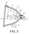
- a light source device having a reflector according to another embodiment of the present invention will be described.
- the same components or portions as those shown in Fig. 1 will be assigned the same reference symbols, thereby to omit explanation thereof.
- the outer surface, i.e. the back side, of the mirror base member 11 is subjected to formation of a small disfigurement through contact with other members. If such a disfigurement exists, a stress is concentrated to a location of the disfigurement when the reflector 10 is heated, resulting in a possibility of breakage of the mirror base member 11 starting from that location.
- a convex portion is represented by 11 d
- a concave portion is represented by 11e.
- a disfigurement is formed only on the convex portions 11d, and is unlikely to be formed on the concave portions 11e being valleys between the convex portions 11d.
- the reflector 10 is heated, a stress tends to be concentrated to the concave portions 11e.
- a disfigurement is unlikely to be formed on the concave portions 11e, so that concentration of the stress to the disfigurement can be prevented.
- the size and number of the convex and concave portions 11 d and 11e may be designed properly such that when the back side of the mirror base member 11 abuts upon another member, a disfigurement is formed only on the convex portions 11d and not formed on the concave portions 11e. Accordingly, the back side of the mirror base member 11 may be formed such that, for example, the center line average height (Ra) in JIS B0601 is 10 ⁇ m or greater, and preferably, 100 ⁇ m or greater.
- the convex and concave portions 11 d and 11e may be formed over the entire back side of the mirror base member, or only at those portions that tend to abut upon another member.
- aluminosilicate glass As a material of the glass member, aluminosilicate glass, borosilicate glass or crystallized glass is suitable, but the best is aluminosilicate glass. As compared with borosilicate glass, aluminosilicate glass is excellent in heat resistance and is liable to be increased in its strength by ion exchange. More specifically, aluminosilicate glass preferably has a composition of 50 to 80 mass% of SiO 2 , 5 to 35 mass% of Al 2 O 3 and 0.5 to 15 mass% of Li 2 O+Na 2 O.
- SiO 2 is a component serving to form a network of the glass.
- the content of SiO 2 falls within a range of 50 to 80 mass%, preferably, within a range of 55 to 75 mass%, and more preferably, within a range of 60 to 72 mass%. If the content of SiO 2 is less than 50 mass%, the strain point is lowered, while the thermal expansion coefficient becomes extremely large, so that the heat/impact resistance is lowered. If the content of SiO 2 is greater than 80 mass%, melting of the glass is made difficult.
- Li 2 O and Na 2 O are components serving to adjust the viscosity of the glass, while replaced in ion exchange.
- the total content of Li 2 O and Na 2 O falls within a range of 0.5 to 15 mass%, preferably, within a range of 1 to 10 mass%, and more preferably, within a range of 3 to 8 mass%. If the total content of Li 2 O and Na 2 O is less than 0.5 mass%, sufficient strength can not be attained even after execution of the ion exchange. If the total content of Li 2 O and Na 2 O is greater than 15 mass%, the glass is liable to be devitrified. Particularly, when Li 2 O in the glass is replaced with Na 2 O in the ion exchange, the strength is liable to be improved. Thus, it is desirable to contain 1 to 7 mass% of Li 2 O.
- the glass can also contain K 2 O, MgO, CaO, ZnO, BaO, B 2 O 3 , TiO 2 , ZrO 2 , P 2 O 5 and the like up to 10 mass%, respectively, and a fining agent up to 2 mass% for the purpose of adjusting the viscosity, thermal expansion coefficient, devitrification property, melting property and the like.
- As a fining agent As a fining agent, As 2 O 3 , Sb 2 O 3 , SnO 2 , Cl or the like may be used alone, or a plurality of them may be properly combined. On the other hand, it is better not to use As 2 O 3 in view of environment because it is harmful.
- borosilicate glass preferably has a composition of 70 to 85 mass% of SiO 2 , 5 to 18 mass% of B 2 O 3 , 1 to 5 mass% of Al 2 O 3 and 3 to 10 mass% of Li 2 O+Na 2 O, and the average thermal expansion coefficient thereof in a temperature range of 30 to 380°C is preferably 40 x 10 -7 /°C or less.
- the reason for limiting the composition of borosilicate glass as noted above is as follows. If the content of SiO 2 is less than 70 mass%, the thermal expansion coefficient is increased, while the heat resistance is lowered. On the other hand, if the content of SiO 2 is greater than 85 mass%, the melting property of the glass is lowered. If the content of B 2 O 3 is less than 5 mass%, the melting property of the glass is lowered, and if it is greater than 18 mass%, the chemical durability is lowered so that the glass becomes unstable. If the content of Al 2 O 3 is less than 1 mass%, the chemical durability is lowered so that the glass becomes unstable, and if it is greater than 5 mass%, the melting property of the glass is lowered.
- Li 2 O and Na 2 O are less than 3 mass%, the melting property of the glass is lowered and the strengthening by the ion exchange is made difficult, and if it is greater than 10 mass%, the thermal expansion coefficient is increased and the heat resistance tends to be lowered.
- Cl 2 , F 2 , Sb 2 O 3 , As 2 O 3 , Bi 2 O 3 , CaO, ZrO 2 and the like may be contained up to 3 mass% in the total content thereof.
- crystallized glass preferably has a composition of 55 to 80 mass% of SiO 2 , 15 to 30 mass% of Al 2 O 3 , 1 to 10 mass% of Li 2 O+Na 2 O, 0 to 10 mass% of K 2 O, 0.5 to 5 mass% of MgO+CaO+BaO+ZnO, 0.5 to 10 mass% of TiO 2 +ZrO 2 +P 2 O 5 and 0 to 2 mass% of As 2 O 3 +Sb 2 O 3 , and precipitates ⁇ -quartz solid solution crystal or ⁇ -Spodumene crystal through a heat treatment, and the average thermal expansion coefficient in a temperature range of 30 to 380°C preferably falls within a range of -10 ⁇ 10 -7 to 25 x 10 -7 /°C.
- the reason for limiting the composition of crystallized glass as noted above is as follows. If the content of SiO 2 is less than 55 mass%, the glass is liable to be devitrified, and if it is greater than 80 mass%, melting of the glass is made difficult. If the content of Al 2 O 3 is less than 15 mass%, the thermal expansion coefficient is increased and the heat resistance is lowered, and if it is greater than 30 mass%, melting of the glass is made difficult. If the total content of Li 2 O and Na 2 O is less than 1 mass%, the melting property of the glass is lowered and the strengthening by the ion exchange is made difficult.
- the thermal expansion coefficient is increased and the heat resistance is lowered. If the total content of MaO, CaO, BaO and ZnO is less than 0.5 mass%, melting of the glass is made difficult, and if it is greater than 5 mass%, the thermal expansion coefficient is increased and the heat resistance is lowered.
- TiO 2 , ZrO 2 and P 2 O 5 act as nucleus forming agents. If the total content of these components is less than 0.5 mass%, crystallization is made difficult, and if it is greater than 10 mass%, melting of the glass is made difficult. As 2 O 3 and Sb 2 O 3 act as fining agents and can be added up to 2 mass%.
- the mirror base member 11 of the reflector 10 of each of the light source devices shown in Figs. 1 and 3 is formed into an approximately bowl shape by a press molding method. If the surface roughness (Ra) of the concave surface on the front side of the mirror base member 11 after the formation thereof is 0.05 ⁇ m or greater, irregular reflection of light is caused and the chemical solution used for the ion exchange remains, so that the film formability tends to be lowered. In this event, therefore, it is necessary to polish the surface to render the surface roughness (Ra) less than 0.05 ⁇ m, preferably, 0.03 ⁇ m or less.
- the protective glass plate 13 is sealingly attached to the front side of the mirror base member 11 using glass frit of a low melting point.
- the protective glass plate 13 is preferably made of the same material as that of the mirror base member 11 for achieving an excellent sealing state.
- an antireflection film is preferably formed on one side or each of both sides of the protective glass plate 13. With this arrangement, reflection of light, which has been radiated from the light source lamp 14, on the surface of the protective glass plate 13 can be suppressed so that a high-intensity projecting or lighting device can be obtained.
- the antireflection film also functions to suppress lowering of the strength and transmittance of the protective glass plate 13.
- the antireflection film is formed on the surface of the protective glass plate 13, it will serve as a barrier layer to prevent an occurrence of replacement between alkali metal ions in the glass and water in the air, so that the lowering of the mechanical strength and the generation of the cloudiness can be prevented.
- the antireflection film is formed on each of both sides of the protective glass plate 13, rather than formed only on one side thereof.
- a multilayer film that is formed by stacking high refractive index films and low refractive index films alternately in 3 to 10 layers and that has a thermal expansion coefficient of 30 x 10 -7 to 50 x 10 - 7 /°C in a temperature range of 30 to 380°C is suitable.
- a high refractive index film a film of TiO 2 , Ta 2 O 5 , Nb 2 O 5 or the like is suitable.
- a low refractive index film a film of SiO 2 , MgF 2 or the like is suitable.
- a film in the form of alternate layers of TiO 2 and SiO 2 is desirable because it is excellent in film formability and heat resistance, and in addition, it is low-cost.
- a film forming method sputtering or vacuum deposition can be used.
- the protective glass plate is made of borosilicate glass having a thickness of about 5.0mm.
- the thickness is preferably set to 3.0mm or less, and more preferably, set to 2.5mm or less.
- the thickness should be set to 0.5mm or greater.
- the protective glass plate 13 may be formed into a plate shape using a molding method such as a float method, a down draw method or a rollout method.
- the surface roughness (Ra) is set to less than 0.01 ⁇ m. If the roughness of the formed surface is large, the surface may be polished to a desired roughness value.
- the protective glass plate 13 has a transmittance of, preferably 95% or greater, and more preferably 97% or greater, within a wavelength range of 420 to 720 nm.
- Table 1 shows glass compositions of a mirror base member of a reflector according to examples 1 to 3. (mass%) Example 1 Example 2 Example 3 SiO 2 66% 79% 66% Al 2 O 3 22% 3% 22% Li 2 O 4% - 4% Na 2 O 0.5% 4.5% 0.5% K 2 O 0.5% - 0.5% TiO 2 2% - 2% ZrO 2 2% - 2% P 2 O 5 1.5% - 1.5% BaO 0.5% - 0.5% B 2 O 3 - 13.5% - Sb 2 O 3 1% - 1% kind of glass aluminosilicate glass borosilicate glass crystallized glass
- the average thermal expansion coefficient in a temperature range of 30 to 380°C was 43 x 10 -7 /°C, and a strong compressive stress layer was formed in the surface thereof.
- a reflecting film in the form of alternate 40 layers of TiO 2 and SiO 2 was formed by vacuum deposition.
- the average thermal expansion coefficient in a temperature range of 30 to 380°C was 33 x 10 -7 /°C, and a strong compressive stress layer was formed in the surface thereof.
- a reflecting film in the form of alternate 40 layers of TiO 2 and SiO 2 was formed by vacuum deposition.
- the glass mirror base member was put into an electric furnace where it was subjected to a heat treatment according to a temperature schedule including a nucleus forming process at 780°C for 2 hours and a crystal growing process at 1160°C for 1 hour, thereby to achieve crystallization, and then cooled slowly.
- the temperature raising speed was 300°C/hour from a room temperature to a nucleus forming temperature, and 100 to 200°C/hour from the nucleus forming temperature to a crystal growing temperature.
- the glass mirror base member was immersed in a tub of KNO 3 (potassium nitrate) held to 500°C, for 24 hours.
- a protective glass plate of example 4 given in Table 2 was prepared in the following manner.
- the glass plate was immersed in a tub of KNO 3 (potassium nitrate) held to 500°C, for 6 hours, to carry out an ion exchange process, so that a strong compressive stress layer was formed in the surface of the glass plate. Then, on each of both sides of the glass plate, an antireflection film in the form of alternate 8 layers of TiO 2 and SiO 2 was formed by sputtering.
- KNO 3 potassium nitrate
- a rectangular glass plate was formed in the same manner as example 4, then, without performing an ion exchange process, an antireflection film in the form of alternate 8 layers of TiO 2 and SiO 2 was formed by sputtering on each of both sides of the glass plate.
- a material adjusted to have the glass composition of comparative example 2 defined in Table 2 was put into a platinum crucible and melted in an electric furnace at approximately 1550°C, then subjected to roll forming to be formed into a plate having a thickness of 5mm, and then cut into a rectangular glass plate having a size of about 60 x 65mm. Thereafter, without performing an ion exchange process, an antireflection film in the form of alternate 8 layers of TiO 2 and SiO 2 was formed by sputtering on each of both sides of the glass plate.
- the protective glass plates of example 4 and comparative examples 1 and 2 thus obtained were subjected to a drop strength test.
- a conical deadweight (200g) with a round tip was dropped onto the glass plate, and a dropping height was started from 10cm and then increased per 10cm.
- the protective glass plates of comparative examples 1 and 2 were both broken when the deadweight was dropped from the initial height of 10cm.
- the protective glass plate of example 4 was broken when the deadweight was dropped from the height of 60cm.
- the protected glass plate of example 4 was heated under the same condition as noted above, its visible light transmittance was measured using a spectrophotometer. The result is shown in Fig. 4. As seen from Fig. 4, the protective glass plate had a transmittance of 95% or greater within a wavelength range of 420 to 720 nm.
- the protective glass plate of example 4 has the enhanced mechanical strength because it has been subjected to ion exchange, and can prevent lowering of the strength and transmittance of the glass plate even if subjected to heating, because the antireflection films are formed on both sides thereof.
Landscapes
- Chemical & Material Sciences (AREA)
- Engineering & Computer Science (AREA)
- Geochemistry & Mineralogy (AREA)
- Life Sciences & Earth Sciences (AREA)
- Chemical Kinetics & Catalysis (AREA)
- General Chemical & Material Sciences (AREA)
- Materials Engineering (AREA)
- Organic Chemistry (AREA)
- General Engineering & Computer Science (AREA)
- Physics & Mathematics (AREA)
- General Physics & Mathematics (AREA)
- Computer Security & Cryptography (AREA)
- Optical Elements Other Than Lenses (AREA)
- Glass Compositions (AREA)
Applications Claiming Priority (11)
| Application Number | Priority Date | Filing Date | Title |
|---|---|---|---|
| JP2001258097 | 2001-08-28 | ||
| JP2001258097 | 2001-08-28 | ||
| JP2001330106 | 2001-10-29 | ||
| JP2001330106 | 2001-10-29 | ||
| JP2002105220 | 2002-04-08 | ||
| JP2002105223 | 2002-04-08 | ||
| JP2002105223 | 2002-04-08 | ||
| JP2002105220 | 2002-04-08 | ||
| JP2002131784 | 2002-05-07 | ||
| JP2002131784 | 2002-05-07 | ||
| EP02018967A EP1288564B1 (de) | 2001-08-28 | 2002-08-26 | Kostengünstiger Reflektor mit ausgezeichneter Hitzebeständigkeit |
Related Parent Applications (2)
| Application Number | Title | Priority Date | Filing Date |
|---|---|---|---|
| EP02018967.6 Division | 2002-08-26 | ||
| EP02018967A Division EP1288564B1 (de) | 2001-08-28 | 2002-08-26 | Kostengünstiger Reflektor mit ausgezeichneter Hitzebeständigkeit |
Publications (3)
| Publication Number | Publication Date |
|---|---|
| EP1598594A2 true EP1598594A2 (de) | 2005-11-23 |
| EP1598594A3 EP1598594A3 (de) | 2005-11-30 |
| EP1598594B1 EP1598594B1 (de) | 2007-02-14 |
Family
ID=27531984
Family Applications (2)
| Application Number | Title | Priority Date | Filing Date |
|---|---|---|---|
| EP05017788A Expired - Lifetime EP1598594B1 (de) | 2001-08-28 | 2002-08-26 | Kostengünstiger Reflektor mit ausgezeichneter Hitzebeständigkeit |
| EP02018967A Expired - Lifetime EP1288564B1 (de) | 2001-08-28 | 2002-08-26 | Kostengünstiger Reflektor mit ausgezeichneter Hitzebeständigkeit |
Family Applications After (1)
| Application Number | Title | Priority Date | Filing Date |
|---|---|---|---|
| EP02018967A Expired - Lifetime EP1288564B1 (de) | 2001-08-28 | 2002-08-26 | Kostengünstiger Reflektor mit ausgezeichneter Hitzebeständigkeit |
Country Status (4)
| Country | Link |
|---|---|
| US (1) | US6814453B2 (de) |
| EP (2) | EP1598594B1 (de) |
| CN (1) | CN1274991C (de) |
| DE (2) | DE60207950T2 (de) |
Cited By (2)
| Publication number | Priority date | Publication date | Assignee | Title |
|---|---|---|---|---|
| WO2009143889A1 (de) * | 2008-05-29 | 2009-12-03 | Osram Gesellschaft mit beschränkter Haftung | Explosionsschutz für hochdrucklampe |
| CN102588841A (zh) * | 2012-02-21 | 2012-07-18 | 南京汇兴博业数字设备有限公司 | 温度自适应高亮度led直下式液晶背光模组 |
Families Citing this family (13)
| Publication number | Priority date | Publication date | Assignee | Title |
|---|---|---|---|---|
| WO2004104650A1 (ja) * | 2003-05-21 | 2004-12-02 | Yupo Corporation | 光反射体および面光源装置 |
| JP3863126B2 (ja) * | 2003-06-26 | 2006-12-27 | 旭テクノグラス株式会社 | プロジェクター用ガラス製反射鏡およびその製造方法 |
| GB2419884B (en) | 2003-08-26 | 2008-03-12 | Mitsubishi Rayon Co | Thermoplastic resin composition for light reflector,molded article for light reflector,light reflector & method for producing molded article. |
| US20050099813A1 (en) * | 2003-09-09 | 2005-05-12 | Seiko Epson Corporation | Reflector, auxiliary mirror, light source device and projector |
| US8304078B2 (en) * | 2005-09-12 | 2012-11-06 | Saxon Glass Technologies, Inc. | Chemically strengthened lithium aluminosilicate glass having high strength effective to resist fracture upon flexing |
| JP2008181716A (ja) * | 2007-01-23 | 2008-08-07 | Matsushita Electric Ind Co Ltd | 放電ランプおよび照明装置 |
| DE102008019664A1 (de) * | 2007-04-27 | 2008-10-30 | Fraunhofer-Gesellschaft zur Förderung der angewandten Forschung e.V. | Scheinwerfer für ein Kraftfahrzeug und Verfahren zum Herstellen desselben |
| US20100242953A1 (en) * | 2009-03-27 | 2010-09-30 | Ppg Industries Ohio, Inc. | Solar reflecting mirror having a protective coating and method of making same |
| US9074752B2 (en) | 2009-11-27 | 2015-07-07 | Koninklijke Philips N.V. | Electric reflector lamp and reflector |
| DE102012212462A1 (de) * | 2012-07-17 | 2014-03-20 | Schott Ag | Verfahren zum Herstellen chemisch vorgespannter Glassubstrate |
| US20160190406A1 (en) | 2014-12-24 | 2016-06-30 | Epistar Corporation | Light-emitting device and manufacturing method thereof |
| CN108730939A (zh) * | 2017-04-13 | 2018-11-02 | 光宝电子(广州)有限公司 | 发光装置 |
| JP2019136191A (ja) * | 2018-02-07 | 2019-08-22 | マクセルホールディングス株式会社 | ドライヤー |
Family Cites Families (8)
| Publication number | Priority date | Publication date | Assignee | Title |
|---|---|---|---|---|
| NL7514565A (nl) * | 1975-12-15 | 1977-06-17 | Philips Nv | Lampen voor hoge vermogens. |
| US4192689A (en) * | 1978-05-30 | 1980-03-11 | Ppg Industries, Inc. | Ion exchange strengthening of soda-lime-silica glass |
| EP0341638B1 (de) * | 1988-05-09 | 1994-08-03 | Ichikoh Industries Limited | Scheinwerfer für Kraftfahrzeuge |
| US5613761A (en) * | 1994-09-21 | 1997-03-25 | Raby, Sr.; Frederick R. | Material and method for fabricating a light fixture reflector, and, reflector produced thereby |
| JP3026742B2 (ja) | 1995-08-10 | 2000-03-27 | 旭テクノグラス株式会社 | ガラス反射鏡 |
| JPH09197124A (ja) * | 1996-01-23 | 1997-07-31 | Nippon Electric Glass Co Ltd | ダイクロイックミラー |
| JP2001125194A (ja) * | 1999-10-25 | 2001-05-11 | Seiko Epson Corp | 光源装置およびこれを用いたプロジェクタ |
| US6382816B1 (en) * | 1999-12-23 | 2002-05-07 | General Eectric Company | Protected coating for energy efficient lamp |
-
2002
- 2002-08-26 EP EP05017788A patent/EP1598594B1/de not_active Expired - Lifetime
- 2002-08-26 DE DE60207950T patent/DE60207950T2/de not_active Expired - Lifetime
- 2002-08-26 EP EP02018967A patent/EP1288564B1/de not_active Expired - Lifetime
- 2002-08-26 DE DE60218233T patent/DE60218233T2/de not_active Expired - Lifetime
- 2002-08-27 US US10/228,497 patent/US6814453B2/en not_active Expired - Fee Related
- 2002-08-28 CN CNB021421161A patent/CN1274991C/zh not_active Expired - Fee Related
Cited By (3)
| Publication number | Priority date | Publication date | Assignee | Title |
|---|---|---|---|---|
| WO2009143889A1 (de) * | 2008-05-29 | 2009-12-03 | Osram Gesellschaft mit beschränkter Haftung | Explosionsschutz für hochdrucklampe |
| CN102588841A (zh) * | 2012-02-21 | 2012-07-18 | 南京汇兴博业数字设备有限公司 | 温度自适应高亮度led直下式液晶背光模组 |
| CN102588841B (zh) * | 2012-02-21 | 2015-10-14 | 南京汇兴博业数字设备有限公司 | 温度自适应高亮度led直下式液晶背光模组 |
Also Published As
| Publication number | Publication date |
|---|---|
| CN1407272A (zh) | 2003-04-02 |
| EP1288564B1 (de) | 2005-12-14 |
| EP1598594B1 (de) | 2007-02-14 |
| EP1288564A1 (de) | 2003-03-05 |
| US6814453B2 (en) | 2004-11-09 |
| CN1274991C (zh) | 2006-09-13 |
| DE60207950D1 (de) | 2006-01-19 |
| DE60207950T2 (de) | 2006-06-14 |
| DE60218233T2 (de) | 2007-06-14 |
| EP1598594A3 (de) | 2005-11-30 |
| US20030048553A1 (en) | 2003-03-13 |
| DE60218233D1 (de) | 2007-03-29 |
Similar Documents
| Publication | Publication Date | Title |
|---|---|---|
| EP1288564B1 (de) | Kostengünstiger Reflektor mit ausgezeichneter Hitzebeständigkeit | |
| TWI271389B (en) | Lamp reflector substrate, glass, glass-ceramic materials and process for making the same | |
| JP4400362B2 (ja) | 外部電極蛍光ランプ用外套容器 | |
| CN101585659B (zh) | 外套容器用玻璃 | |
| WO2012157695A1 (ja) | 高屈折率ガラス | |
| JP2009114060A (ja) | ランプ用ガラス組成物およびランプ用ガラス組成物の製造方法 | |
| KR20150031268A (ko) | 결정성 유리 기판, 결정화 유리 기판, 확산판, 및 그것을 구비한 조명 장치 | |
| JP2003327446A (ja) | ガラスを放電灯のランプ球に用いること、並びにランプ球及び放電灯、特にミニチュア放電灯 | |
| JP6066060B2 (ja) | 結晶化ガラス基板及びその製造方法 | |
| US6629768B2 (en) | Lamp with an unpolished surface and radiant source lamps with a transparent cover for the radiant source | |
| JP2004002062A (ja) | フラットパネルディスプレイ装置用ガラス基板 | |
| KR20070114747A (ko) | 램프용 유리조성물, 램프, 백라이트 유닛 및 램프용유리조성물의 제조방법 | |
| JP2005037906A (ja) | 反射鏡及びその製造方法 | |
| JP4305844B2 (ja) | 蛍光ランプ用外套管 | |
| JP2008033345A (ja) | 反射鏡 | |
| JP2004031301A (ja) | 反射鏡 | |
| JP2008158145A (ja) | 反射防止膜及びその反射防止膜を備えた光学物品 | |
| JP2004219995A (ja) | 反射鏡 | |
| CN100401186C (zh) | 具有优良抗热性的低成本反射器 | |
| JP2004071227A (ja) | 反射鏡 | |
| JP4400412B2 (ja) | 外部電極蛍光ランプ用外套容器 | |
| JP5184748B2 (ja) | ガラスおよびガラスセラミックの紫外線吸収を調整する方法ならびにガラスおよびガラスセラミックを有する発光手段 | |
| JP4314535B2 (ja) | 蛍光ランプ用外套管 | |
| JP4190366B2 (ja) | プロジェクター用ガラス製反射鏡の製造方法 | |
| JP2004062009A (ja) | 反射鏡及びその製造方法 |
Legal Events
| Date | Code | Title | Description |
|---|---|---|---|
| PUAI | Public reference made under article 153(3) epc to a published international application that has entered the european phase |
Free format text: ORIGINAL CODE: 0009012 |
|
| PUAL | Search report despatched |
Free format text: ORIGINAL CODE: 0009013 |
|
| AC | Divisional application: reference to earlier application |
Ref document number: 1288564 Country of ref document: EP Kind code of ref document: P |
|
| AK | Designated contracting states |
Kind code of ref document: A2 Designated state(s): AT BE BG CH CY CZ DE DK EE ES FI FR GB GR IE IT LI LU MC NL PT SE SK TR |
|
| AX | Request for extension of the european patent |
Extension state: AL LT LV MK RO SI |
|
| AK | Designated contracting states |
Kind code of ref document: A3 Designated state(s): AT BE BG CH CY CZ DE DK EE ES FI FR GB GR IE IT LI LU MC NL PT SE SK TR |
|
| AX | Request for extension of the european patent |
Extension state: AL LT LV MK RO SI |
|
| AKX | Designation fees paid | ||
| 17P | Request for examination filed |
Effective date: 20060802 |
|
| RBV | Designated contracting states (corrected) |
Designated state(s): DE NL |
|
| GRAP | Despatch of communication of intention to grant a patent |
Free format text: ORIGINAL CODE: EPIDOSNIGR1 |
|
| GRAS | Grant fee paid |
Free format text: ORIGINAL CODE: EPIDOSNIGR3 |
|
| GRAA | (expected) grant |
Free format text: ORIGINAL CODE: 0009210 |
|
| AC | Divisional application: reference to earlier application |
Ref document number: 1288564 Country of ref document: EP Kind code of ref document: P |
|
| AK | Designated contracting states |
Kind code of ref document: B1 Designated state(s): DE NL |
|
| REF | Corresponds to: |
Ref document number: 60218233 Country of ref document: DE Date of ref document: 20070329 Kind code of ref document: P |
|
| PLBE | No opposition filed within time limit |
Free format text: ORIGINAL CODE: 0009261 |
|
| STAA | Information on the status of an ep patent application or granted ep patent |
Free format text: STATUS: NO OPPOSITION FILED WITHIN TIME LIMIT |
|
| 26N | No opposition filed |
Effective date: 20071115 |
|
| PGFP | Annual fee paid to national office [announced via postgrant information from national office to epo] |
Ref country code: DE Payment date: 20120822 Year of fee payment: 11 |
|
| PGFP | Annual fee paid to national office [announced via postgrant information from national office to epo] |
Ref country code: NL Payment date: 20120816 Year of fee payment: 11 |
|
| REG | Reference to a national code |
Ref country code: NL Ref legal event code: V1 Effective date: 20140301 |
|
| PG25 | Lapsed in a contracting state [announced via postgrant information from national office to epo] |
Ref country code: DE Free format text: LAPSE BECAUSE OF NON-PAYMENT OF DUE FEES Effective date: 20140301 Ref country code: NL Free format text: LAPSE BECAUSE OF NON-PAYMENT OF DUE FEES Effective date: 20140301 |
|
| REG | Reference to a national code |
Ref country code: DE Ref legal event code: R119 Ref document number: 60218233 Country of ref document: DE Effective date: 20140301 |