EP1596104B1 - Vorrichtung zum Ansteuern einer Mehrzahl von hydraulischen Schaltzylindern sowie Hydraulikversorgungssystem für ein Doppelkupplungsgetriebe - Google Patents
Vorrichtung zum Ansteuern einer Mehrzahl von hydraulischen Schaltzylindern sowie Hydraulikversorgungssystem für ein Doppelkupplungsgetriebe Download PDFInfo
- Publication number
- EP1596104B1 EP1596104B1 EP20050009198 EP05009198A EP1596104B1 EP 1596104 B1 EP1596104 B1 EP 1596104B1 EP 20050009198 EP20050009198 EP 20050009198 EP 05009198 A EP05009198 A EP 05009198A EP 1596104 B1 EP1596104 B1 EP 1596104B1
- Authority
- EP
- European Patent Office
- Prior art keywords
- pressure
- valve
- control
- line
- shift
- Prior art date
- Legal status (The legal status is an assumption and is not a legal conclusion. Google has not performed a legal analysis and makes no representation as to the accuracy of the status listed.)
- Not-in-force
Links
Images


Classifications
-
- F—MECHANICAL ENGINEERING; LIGHTING; HEATING; WEAPONS; BLASTING
- F15—FLUID-PRESSURE ACTUATORS; HYDRAULICS OR PNEUMATICS IN GENERAL
- F15B—SYSTEMS ACTING BY MEANS OF FLUIDS IN GENERAL; FLUID-PRESSURE ACTUATORS, e.g. SERVOMOTORS; DETAILS OF FLUID-PRESSURE SYSTEMS, NOT OTHERWISE PROVIDED FOR
- F15B11/00—Servomotor systems without provision for follow-up action; Circuits therefor
- F15B11/16—Servomotor systems without provision for follow-up action; Circuits therefor with two or more servomotors
- F15B11/17—Servomotor systems without provision for follow-up action; Circuits therefor with two or more servomotors using two or more pumps
-
- F—MECHANICAL ENGINEERING; LIGHTING; HEATING; WEAPONS; BLASTING
- F16—ENGINEERING ELEMENTS AND UNITS; GENERAL MEASURES FOR PRODUCING AND MAINTAINING EFFECTIVE FUNCTIONING OF MACHINES OR INSTALLATIONS; THERMAL INSULATION IN GENERAL
- F16H—GEARING
- F16H61/00—Control functions within control units of change-speed- or reversing-gearings for conveying rotary motion ; Control of exclusively fluid gearing, friction gearing, gearings with endless flexible members or other particular types of gearing
- F16H61/26—Generation or transmission of movements for final actuating mechanisms
- F16H61/28—Generation or transmission of movements for final actuating mechanisms with at least one movement of the final actuating mechanism being caused by a non-mechanical force, e.g. power-assisted
-
- F—MECHANICAL ENGINEERING; LIGHTING; HEATING; WEAPONS; BLASTING
- F15—FLUID-PRESSURE ACTUATORS; HYDRAULICS OR PNEUMATICS IN GENERAL
- F15B—SYSTEMS ACTING BY MEANS OF FLUIDS IN GENERAL; FLUID-PRESSURE ACTUATORS, e.g. SERVOMOTORS; DETAILS OF FLUID-PRESSURE SYSTEMS, NOT OTHERWISE PROVIDED FOR
- F15B11/00—Servomotor systems without provision for follow-up action; Circuits therefor
- F15B11/02—Systems essentially incorporating special features for controlling the speed or actuating force of an output member
- F15B11/04—Systems essentially incorporating special features for controlling the speed or actuating force of an output member for controlling the speed
- F15B11/044—Systems essentially incorporating special features for controlling the speed or actuating force of an output member for controlling the speed by means in the return line, i.e. "meter out"
-
- F—MECHANICAL ENGINEERING; LIGHTING; HEATING; WEAPONS; BLASTING
- F16—ENGINEERING ELEMENTS AND UNITS; GENERAL MEASURES FOR PRODUCING AND MAINTAINING EFFECTIVE FUNCTIONING OF MACHINES OR INSTALLATIONS; THERMAL INSULATION IN GENERAL
- F16D—COUPLINGS FOR TRANSMITTING ROTATION; CLUTCHES; BRAKES
- F16D48/00—External control of clutches
- F16D48/02—Control by fluid pressure
- F16D48/0206—Control by fluid pressure in a system with a plurality of fluid-actuated clutches
-
- F—MECHANICAL ENGINEERING; LIGHTING; HEATING; WEAPONS; BLASTING
- F16—ENGINEERING ELEMENTS AND UNITS; GENERAL MEASURES FOR PRODUCING AND MAINTAINING EFFECTIVE FUNCTIONING OF MACHINES OR INSTALLATIONS; THERMAL INSULATION IN GENERAL
- F16H—GEARING
- F16H61/00—Control functions within control units of change-speed- or reversing-gearings for conveying rotary motion ; Control of exclusively fluid gearing, friction gearing, gearings with endless flexible members or other particular types of gearing
- F16H61/02—Control functions within control units of change-speed- or reversing-gearings for conveying rotary motion ; Control of exclusively fluid gearing, friction gearing, gearings with endless flexible members or other particular types of gearing characterised by the signals used
- F16H61/0262—Control functions within control units of change-speed- or reversing-gearings for conveying rotary motion ; Control of exclusively fluid gearing, friction gearing, gearings with endless flexible members or other particular types of gearing characterised by the signals used the signals being hydraulic
- F16H61/0265—Control functions within control units of change-speed- or reversing-gearings for conveying rotary motion ; Control of exclusively fluid gearing, friction gearing, gearings with endless flexible members or other particular types of gearing characterised by the signals used the signals being hydraulic for gearshift control, e.g. control functions for performing shifting or generation of shift signals
- F16H61/0267—Layout of hydraulic control circuits, e.g. arrangement of valves
-
- F—MECHANICAL ENGINEERING; LIGHTING; HEATING; WEAPONS; BLASTING
- F16—ENGINEERING ELEMENTS AND UNITS; GENERAL MEASURES FOR PRODUCING AND MAINTAINING EFFECTIVE FUNCTIONING OF MACHINES OR INSTALLATIONS; THERMAL INSULATION IN GENERAL
- F16H—GEARING
- F16H61/00—Control functions within control units of change-speed- or reversing-gearings for conveying rotary motion ; Control of exclusively fluid gearing, friction gearing, gearings with endless flexible members or other particular types of gearing
- F16H61/02—Control functions within control units of change-speed- or reversing-gearings for conveying rotary motion ; Control of exclusively fluid gearing, friction gearing, gearings with endless flexible members or other particular types of gearing characterised by the signals used
- F16H61/0262—Control functions within control units of change-speed- or reversing-gearings for conveying rotary motion ; Control of exclusively fluid gearing, friction gearing, gearings with endless flexible members or other particular types of gearing characterised by the signals used the signals being hydraulic
- F16H61/0276—Elements specially adapted for hydraulic control units, e.g. valves
-
- F—MECHANICAL ENGINEERING; LIGHTING; HEATING; WEAPONS; BLASTING
- F15—FLUID-PRESSURE ACTUATORS; HYDRAULICS OR PNEUMATICS IN GENERAL
- F15B—SYSTEMS ACTING BY MEANS OF FLUIDS IN GENERAL; FLUID-PRESSURE ACTUATORS, e.g. SERVOMOTORS; DETAILS OF FLUID-PRESSURE SYSTEMS, NOT OTHERWISE PROVIDED FOR
- F15B2211/00—Circuits for servomotor systems
- F15B2211/20—Fluid pressure source, e.g. accumulator or variable axial piston pump
- F15B2211/205—Systems with pumps
- F15B2211/2053—Type of pump
- F15B2211/20538—Type of pump constant capacity
-
- F—MECHANICAL ENGINEERING; LIGHTING; HEATING; WEAPONS; BLASTING
- F15—FLUID-PRESSURE ACTUATORS; HYDRAULICS OR PNEUMATICS IN GENERAL
- F15B—SYSTEMS ACTING BY MEANS OF FLUIDS IN GENERAL; FLUID-PRESSURE ACTUATORS, e.g. SERVOMOTORS; DETAILS OF FLUID-PRESSURE SYSTEMS, NOT OTHERWISE PROVIDED FOR
- F15B2211/00—Circuits for servomotor systems
- F15B2211/30—Directional control
- F15B2211/305—Directional control characterised by the type of valves
- F15B2211/30505—Non-return valves, i.e. check valves
-
- F—MECHANICAL ENGINEERING; LIGHTING; HEATING; WEAPONS; BLASTING
- F15—FLUID-PRESSURE ACTUATORS; HYDRAULICS OR PNEUMATICS IN GENERAL
- F15B—SYSTEMS ACTING BY MEANS OF FLUIDS IN GENERAL; FLUID-PRESSURE ACTUATORS, e.g. SERVOMOTORS; DETAILS OF FLUID-PRESSURE SYSTEMS, NOT OTHERWISE PROVIDED FOR
- F15B2211/00—Circuits for servomotor systems
- F15B2211/30—Directional control
- F15B2211/305—Directional control characterised by the type of valves
- F15B2211/3056—Assemblies of multiple valves
- F15B2211/30585—Assemblies of multiple valves having a single valve for multiple output members
-
- F—MECHANICAL ENGINEERING; LIGHTING; HEATING; WEAPONS; BLASTING
- F15—FLUID-PRESSURE ACTUATORS; HYDRAULICS OR PNEUMATICS IN GENERAL
- F15B—SYSTEMS ACTING BY MEANS OF FLUIDS IN GENERAL; FLUID-PRESSURE ACTUATORS, e.g. SERVOMOTORS; DETAILS OF FLUID-PRESSURE SYSTEMS, NOT OTHERWISE PROVIDED FOR
- F15B2211/00—Circuits for servomotor systems
- F15B2211/30—Directional control
- F15B2211/305—Directional control characterised by the type of valves
- F15B2211/3056—Assemblies of multiple valves
- F15B2211/3059—Assemblies of multiple valves having multiple valves for multiple output members
-
- F—MECHANICAL ENGINEERING; LIGHTING; HEATING; WEAPONS; BLASTING
- F15—FLUID-PRESSURE ACTUATORS; HYDRAULICS OR PNEUMATICS IN GENERAL
- F15B—SYSTEMS ACTING BY MEANS OF FLUIDS IN GENERAL; FLUID-PRESSURE ACTUATORS, e.g. SERVOMOTORS; DETAILS OF FLUID-PRESSURE SYSTEMS, NOT OTHERWISE PROVIDED FOR
- F15B2211/00—Circuits for servomotor systems
- F15B2211/30—Directional control
- F15B2211/31—Directional control characterised by the positions of the valve element
- F15B2211/3122—Special positions other than the pump port being connected to working ports or the working ports being connected to the return line
- F15B2211/3127—Floating position connecting the working ports and the return line
-
- F—MECHANICAL ENGINEERING; LIGHTING; HEATING; WEAPONS; BLASTING
- F15—FLUID-PRESSURE ACTUATORS; HYDRAULICS OR PNEUMATICS IN GENERAL
- F15B—SYSTEMS ACTING BY MEANS OF FLUIDS IN GENERAL; FLUID-PRESSURE ACTUATORS, e.g. SERVOMOTORS; DETAILS OF FLUID-PRESSURE SYSTEMS, NOT OTHERWISE PROVIDED FOR
- F15B2211/00—Circuits for servomotor systems
- F15B2211/30—Directional control
- F15B2211/32—Directional control characterised by the type of actuation
- F15B2211/329—Directional control characterised by the type of actuation actuated by fluid pressure
-
- F—MECHANICAL ENGINEERING; LIGHTING; HEATING; WEAPONS; BLASTING
- F15—FLUID-PRESSURE ACTUATORS; HYDRAULICS OR PNEUMATICS IN GENERAL
- F15B—SYSTEMS ACTING BY MEANS OF FLUIDS IN GENERAL; FLUID-PRESSURE ACTUATORS, e.g. SERVOMOTORS; DETAILS OF FLUID-PRESSURE SYSTEMS, NOT OTHERWISE PROVIDED FOR
- F15B2211/00—Circuits for servomotor systems
- F15B2211/40—Flow control
- F15B2211/405—Flow control characterised by the type of flow control means or valve
- F15B2211/40507—Flow control characterised by the type of flow control means or valve with constant throttles or orifices
-
- F—MECHANICAL ENGINEERING; LIGHTING; HEATING; WEAPONS; BLASTING
- F15—FLUID-PRESSURE ACTUATORS; HYDRAULICS OR PNEUMATICS IN GENERAL
- F15B—SYSTEMS ACTING BY MEANS OF FLUIDS IN GENERAL; FLUID-PRESSURE ACTUATORS, e.g. SERVOMOTORS; DETAILS OF FLUID-PRESSURE SYSTEMS, NOT OTHERWISE PROVIDED FOR
- F15B2211/00—Circuits for servomotor systems
- F15B2211/40—Flow control
- F15B2211/46—Control of flow in the return line, i.e. meter-out control
-
- F—MECHANICAL ENGINEERING; LIGHTING; HEATING; WEAPONS; BLASTING
- F15—FLUID-PRESSURE ACTUATORS; HYDRAULICS OR PNEUMATICS IN GENERAL
- F15B—SYSTEMS ACTING BY MEANS OF FLUIDS IN GENERAL; FLUID-PRESSURE ACTUATORS, e.g. SERVOMOTORS; DETAILS OF FLUID-PRESSURE SYSTEMS, NOT OTHERWISE PROVIDED FOR
- F15B2211/00—Circuits for servomotor systems
- F15B2211/50—Pressure control
- F15B2211/505—Pressure control characterised by the type of pressure control means
- F15B2211/50509—Pressure control characterised by the type of pressure control means the pressure control means controlling a pressure upstream of the pressure control means
- F15B2211/50518—Pressure control characterised by the type of pressure control means the pressure control means controlling a pressure upstream of the pressure control means using pressure relief valves
-
- F—MECHANICAL ENGINEERING; LIGHTING; HEATING; WEAPONS; BLASTING
- F15—FLUID-PRESSURE ACTUATORS; HYDRAULICS OR PNEUMATICS IN GENERAL
- F15B—SYSTEMS ACTING BY MEANS OF FLUIDS IN GENERAL; FLUID-PRESSURE ACTUATORS, e.g. SERVOMOTORS; DETAILS OF FLUID-PRESSURE SYSTEMS, NOT OTHERWISE PROVIDED FOR
- F15B2211/00—Circuits for servomotor systems
- F15B2211/50—Pressure control
- F15B2211/505—Pressure control characterised by the type of pressure control means
- F15B2211/50554—Pressure control characterised by the type of pressure control means the pressure control means controlling a pressure downstream of the pressure control means, e.g. pressure reducing valve
-
- F—MECHANICAL ENGINEERING; LIGHTING; HEATING; WEAPONS; BLASTING
- F15—FLUID-PRESSURE ACTUATORS; HYDRAULICS OR PNEUMATICS IN GENERAL
- F15B—SYSTEMS ACTING BY MEANS OF FLUIDS IN GENERAL; FLUID-PRESSURE ACTUATORS, e.g. SERVOMOTORS; DETAILS OF FLUID-PRESSURE SYSTEMS, NOT OTHERWISE PROVIDED FOR
- F15B2211/00—Circuits for servomotor systems
- F15B2211/50—Pressure control
- F15B2211/55—Pressure control for limiting a pressure up to a maximum pressure, e.g. by using a pressure relief valve
-
- F—MECHANICAL ENGINEERING; LIGHTING; HEATING; WEAPONS; BLASTING
- F15—FLUID-PRESSURE ACTUATORS; HYDRAULICS OR PNEUMATICS IN GENERAL
- F15B—SYSTEMS ACTING BY MEANS OF FLUIDS IN GENERAL; FLUID-PRESSURE ACTUATORS, e.g. SERVOMOTORS; DETAILS OF FLUID-PRESSURE SYSTEMS, NOT OTHERWISE PROVIDED FOR
- F15B2211/00—Circuits for servomotor systems
- F15B2211/60—Circuit components or control therefor
- F15B2211/61—Secondary circuits
- F15B2211/611—Diverting circuits, e.g. for cooling or filtering
-
- F—MECHANICAL ENGINEERING; LIGHTING; HEATING; WEAPONS; BLASTING
- F15—FLUID-PRESSURE ACTUATORS; HYDRAULICS OR PNEUMATICS IN GENERAL
- F15B—SYSTEMS ACTING BY MEANS OF FLUIDS IN GENERAL; FLUID-PRESSURE ACTUATORS, e.g. SERVOMOTORS; DETAILS OF FLUID-PRESSURE SYSTEMS, NOT OTHERWISE PROVIDED FOR
- F15B2211/00—Circuits for servomotor systems
- F15B2211/60—Circuit components or control therefor
- F15B2211/615—Filtering means
-
- F—MECHANICAL ENGINEERING; LIGHTING; HEATING; WEAPONS; BLASTING
- F15—FLUID-PRESSURE ACTUATORS; HYDRAULICS OR PNEUMATICS IN GENERAL
- F15B—SYSTEMS ACTING BY MEANS OF FLUIDS IN GENERAL; FLUID-PRESSURE ACTUATORS, e.g. SERVOMOTORS; DETAILS OF FLUID-PRESSURE SYSTEMS, NOT OTHERWISE PROVIDED FOR
- F15B2211/00—Circuits for servomotor systems
- F15B2211/60—Circuit components or control therefor
- F15B2211/62—Cooling or heating means
-
- F—MECHANICAL ENGINEERING; LIGHTING; HEATING; WEAPONS; BLASTING
- F15—FLUID-PRESSURE ACTUATORS; HYDRAULICS OR PNEUMATICS IN GENERAL
- F15B—SYSTEMS ACTING BY MEANS OF FLUIDS IN GENERAL; FLUID-PRESSURE ACTUATORS, e.g. SERVOMOTORS; DETAILS OF FLUID-PRESSURE SYSTEMS, NOT OTHERWISE PROVIDED FOR
- F15B2211/00—Circuits for servomotor systems
- F15B2211/70—Output members, e.g. hydraulic motors or cylinders or control therefor
- F15B2211/705—Output members, e.g. hydraulic motors or cylinders or control therefor characterised by the type of output members or actuators
- F15B2211/7051—Linear output members
- F15B2211/7052—Single-acting output members
-
- F—MECHANICAL ENGINEERING; LIGHTING; HEATING; WEAPONS; BLASTING
- F15—FLUID-PRESSURE ACTUATORS; HYDRAULICS OR PNEUMATICS IN GENERAL
- F15B—SYSTEMS ACTING BY MEANS OF FLUIDS IN GENERAL; FLUID-PRESSURE ACTUATORS, e.g. SERVOMOTORS; DETAILS OF FLUID-PRESSURE SYSTEMS, NOT OTHERWISE PROVIDED FOR
- F15B2211/00—Circuits for servomotor systems
- F15B2211/70—Output members, e.g. hydraulic motors or cylinders or control therefor
- F15B2211/71—Multiple output members, e.g. multiple hydraulic motors or cylinders
-
- F—MECHANICAL ENGINEERING; LIGHTING; HEATING; WEAPONS; BLASTING
- F15—FLUID-PRESSURE ACTUATORS; HYDRAULICS OR PNEUMATICS IN GENERAL
- F15B—SYSTEMS ACTING BY MEANS OF FLUIDS IN GENERAL; FLUID-PRESSURE ACTUATORS, e.g. SERVOMOTORS; DETAILS OF FLUID-PRESSURE SYSTEMS, NOT OTHERWISE PROVIDED FOR
- F15B2211/00—Circuits for servomotor systems
- F15B2211/70—Output members, e.g. hydraulic motors or cylinders or control therefor
- F15B2211/78—Control of multiple output members
-
- F—MECHANICAL ENGINEERING; LIGHTING; HEATING; WEAPONS; BLASTING
- F16—ENGINEERING ELEMENTS AND UNITS; GENERAL MEASURES FOR PRODUCING AND MAINTAINING EFFECTIVE FUNCTIONING OF MACHINES OR INSTALLATIONS; THERMAL INSULATION IN GENERAL
- F16D—COUPLINGS FOR TRANSMITTING ROTATION; CLUTCHES; BRAKES
- F16D48/00—External control of clutches
- F16D48/02—Control by fluid pressure
- F16D2048/0221—Valves for clutch control systems; Details thereof
-
- F—MECHANICAL ENGINEERING; LIGHTING; HEATING; WEAPONS; BLASTING
- F16—ENGINEERING ELEMENTS AND UNITS; GENERAL MEASURES FOR PRODUCING AND MAINTAINING EFFECTIVE FUNCTIONING OF MACHINES OR INSTALLATIONS; THERMAL INSULATION IN GENERAL
- F16D—COUPLINGS FOR TRANSMITTING ROTATION; CLUTCHES; BRAKES
- F16D48/00—External control of clutches
- F16D48/02—Control by fluid pressure
- F16D2048/0257—Hydraulic circuit layouts, i.e. details of hydraulic circuit elements or the arrangement thereof
- F16D2048/0281—Complex circuits with more than two valves in series or special arrangements thereof not provided for in previous groups
-
- F—MECHANICAL ENGINEERING; LIGHTING; HEATING; WEAPONS; BLASTING
- F16—ENGINEERING ELEMENTS AND UNITS; GENERAL MEASURES FOR PRODUCING AND MAINTAINING EFFECTIVE FUNCTIONING OF MACHINES OR INSTALLATIONS; THERMAL INSULATION IN GENERAL
- F16D—COUPLINGS FOR TRANSMITTING ROTATION; CLUTCHES; BRAKES
- F16D2500/00—External control of clutches by electric or electronic means
- F16D2500/10—System to be controlled
- F16D2500/102—Actuator
- F16D2500/1021—Electrical type
- F16D2500/1023—Electric motor
- F16D2500/1024—Electric motor combined with hydraulic actuation
-
- F—MECHANICAL ENGINEERING; LIGHTING; HEATING; WEAPONS; BLASTING
- F16—ENGINEERING ELEMENTS AND UNITS; GENERAL MEASURES FOR PRODUCING AND MAINTAINING EFFECTIVE FUNCTIONING OF MACHINES OR INSTALLATIONS; THERMAL INSULATION IN GENERAL
- F16D—COUPLINGS FOR TRANSMITTING ROTATION; CLUTCHES; BRAKES
- F16D2500/00—External control of clutches by electric or electronic means
- F16D2500/70—Details about the implementation of the control system
- F16D2500/704—Output parameters from the control unit; Target parameters to be controlled
- F16D2500/70402—Actuator parameters
- F16D2500/70406—Pressure
-
- F—MECHANICAL ENGINEERING; LIGHTING; HEATING; WEAPONS; BLASTING
- F16—ENGINEERING ELEMENTS AND UNITS; GENERAL MEASURES FOR PRODUCING AND MAINTAINING EFFECTIVE FUNCTIONING OF MACHINES OR INSTALLATIONS; THERMAL INSULATION IN GENERAL
- F16H—GEARING
- F16H61/00—Control functions within control units of change-speed- or reversing-gearings for conveying rotary motion ; Control of exclusively fluid gearing, friction gearing, gearings with endless flexible members or other particular types of gearing
- F16H61/02—Control functions within control units of change-speed- or reversing-gearings for conveying rotary motion ; Control of exclusively fluid gearing, friction gearing, gearings with endless flexible members or other particular types of gearing characterised by the signals used
- F16H61/0262—Control functions within control units of change-speed- or reversing-gearings for conveying rotary motion ; Control of exclusively fluid gearing, friction gearing, gearings with endless flexible members or other particular types of gearing characterised by the signals used the signals being hydraulic
- F16H61/0276—Elements specially adapted for hydraulic control units, e.g. valves
- F16H2061/0281—Rotary shift valves, e.g. with a rotary moveable spool for supply of fluid to different channels
-
- F—MECHANICAL ENGINEERING; LIGHTING; HEATING; WEAPONS; BLASTING
- F16—ENGINEERING ELEMENTS AND UNITS; GENERAL MEASURES FOR PRODUCING AND MAINTAINING EFFECTIVE FUNCTIONING OF MACHINES OR INSTALLATIONS; THERMAL INSULATION IN GENERAL
- F16H—GEARING
- F16H61/00—Control functions within control units of change-speed- or reversing-gearings for conveying rotary motion ; Control of exclusively fluid gearing, friction gearing, gearings with endless flexible members or other particular types of gearing
- F16H61/68—Control functions within control units of change-speed- or reversing-gearings for conveying rotary motion ; Control of exclusively fluid gearing, friction gearing, gearings with endless flexible members or other particular types of gearing specially adapted for stepped gearings
- F16H61/684—Control functions within control units of change-speed- or reversing-gearings for conveying rotary motion ; Control of exclusively fluid gearing, friction gearing, gearings with endless flexible members or other particular types of gearing specially adapted for stepped gearings without interruption of drive
- F16H61/688—Control functions within control units of change-speed- or reversing-gearings for conveying rotary motion ; Control of exclusively fluid gearing, friction gearing, gearings with endless flexible members or other particular types of gearing specially adapted for stepped gearings without interruption of drive with two inputs, e.g. selection of one of two torque-flow paths by clutches
-
- Y—GENERAL TAGGING OF NEW TECHNOLOGICAL DEVELOPMENTS; GENERAL TAGGING OF CROSS-SECTIONAL TECHNOLOGIES SPANNING OVER SEVERAL SECTIONS OF THE IPC; TECHNICAL SUBJECTS COVERED BY FORMER USPC CROSS-REFERENCE ART COLLECTIONS [XRACs] AND DIGESTS
- Y10—TECHNICAL SUBJECTS COVERED BY FORMER USPC
- Y10T—TECHNICAL SUBJECTS COVERED BY FORMER US CLASSIFICATION
- Y10T137/00—Fluid handling
- Y10T137/0971—Speed responsive valve control
- Y10T137/1044—With other condition responsive valve control
-
- Y—GENERAL TAGGING OF NEW TECHNOLOGICAL DEVELOPMENTS; GENERAL TAGGING OF CROSS-SECTIONAL TECHNOLOGIES SPANNING OVER SEVERAL SECTIONS OF THE IPC; TECHNICAL SUBJECTS COVERED BY FORMER USPC CROSS-REFERENCE ART COLLECTIONS [XRACs] AND DIGESTS
- Y10—TECHNICAL SUBJECTS COVERED BY FORMER USPC
- Y10T—TECHNICAL SUBJECTS COVERED BY FORMER US CLASSIFICATION
- Y10T74/00—Machine element or mechanism
- Y10T74/19—Gearing
- Y10T74/19219—Interchangeably locked
- Y10T74/19251—Control mechanism
Definitions
- the invention relates to a device for controlling a plurality of hydraulic switching cylinders, in particular shift cylinders for shifting gears of a dual-clutch transmission.
- the invention further relates to a hydraulic supply system for a dual-clutch transmission, comprising such a device.
- an electro-hydraulic transmission control device can be acted upon by hydraulic pressure on the existing clutches, brakes and / or switching mechanisms of an automatic transmission shift cylinder.
- the components of the transmission control device are attached to a module body, are formed in the flow paths. Attached to the module body, designed for example as a slide valves control valves control hydraulic fluid through the flow paths.
- the control valves are controlled by solenoid control valves, which are also mounted on the module body.
- the JP 08109905 A shows a multi-stage bidirectionally operable switching cylinder in which a plurality of chambers with system pressure or with a return can be connected.
- the generic DE 44 32 850 C1 shows an arrangement for controlling a gear change transmission in which two hydraulic actuators are alternately switchable by means of a single electromagnetic control valve in two stationary and two transient switching states.
- the DE 101 25 172 A1 shows a hydraulic shift control device for a multi-speed Zahnzierwechseigetriebe, in which two parallel-connected spool valves each alternately supply a pressure chamber of a released from a switching valve switching cylinder with system pressure.
- the not pre-published EP 1 420 185 A2 shows a motor vehicle powertrain with a transmission control in which a plurality of hydraulic shift cylinders for shifting gears are supplied by a first spool valve with a system pressure input, two outputs to the spool valves and a return port, the two outputs optionally with system pressure or with the return are connectable.
- the invention has for its object to provide a simple in construction device for driving a plurality of hydraulic switching cylinders, in particular for controlling switching cylinders for switching gears of a dual-clutch transmission.
- a known device for controlling a plurality of hydraulic Wegzylindem, in particular shift cylinders for shifting gears of a dual clutch transmission includes: a first slide valve with a control pressure acted upon control input, a system pressure can be acted upon system pressure input, two outputs and at least one return output, wherein, depending on the Control input lying pressure optionally one output to the system pressure input and the other output is connected to the return output, and connected to the outputs of the spool valve means by means of which the switching cylinders are selectively actuated.
- the first slide valve which is generally designed as a 4/3-way valve, and the valve device connected to this slide valve opens up different simple possibilities for constructing the device according to the invention.
- the valve means is formed by slide valves with inputs and outputs and sliders which are movable in a first or second position depending on an application of control pressure, wherein each input of a slide valve associated with two outputs, one of which in the first position the spool and the other thereof in the second position of the spool is connected to the inlet, which spool valves are arranged in tiers in a cascade such that an input of a spool valve of a downstream stage is connected to an output of a spool valve of the preceding stage; first slide valve forms the first stage and the outputs of the slide valves of the last stage are each connected to a shift cylinder, and control means are provided, one of which is associated with the slide valves of a stage, so that all the slide valves of a stage gl at the same time be subjected to tax pressure.
- the second stage of the cascade includes a gate valve with two inputs and four outputs, and a third stage two gate valves with two inputs and four outputs, etc.
- n control devices allow 2 "shift cylinders to be selectively actuated.
- the outputs connectable to the one input of the second-stage spool valve are third stage connected to switching cylinders, with which a first group of gears of the dual-clutch transmission is switchable, and connectable to the other input of the second-stage spool valve outputs of the third stage are connected to switching cylinders, with which a second group of gears is switchable.
- control device for actuating the second stage spool valve is formed by a connection of a control chamber of the spool valve to a hydraulic line via which one of the clutches of the dual clutch transmission can be actuated by pressurization.
- the valve device includes a controllable pressure with multi-way valve with one of the switching cylinder a switching assembly associated individual outputs and one of the other of the switching cylinder of the actuating assemblies together associated collecting output, and the multiway valve selectively directs the system pressure to one of the individual outputs, depending on the position of the first spool valve, thereby connecting all other switching cylinders to the return port or selectively connecting one of the individual ports to the return port, applying all other outputs to the system pressure.
- control devices are formed by electromagnetically actuated control valves.
- a pilot pressure line is preferably connected via a throttle to a connecting line between a control valve and a control chamber of a slide valve.
- the aforesaid valve means includes a rotary valve whose rotary valve selectively connects an input connected to an output of the first spool valve to one of the individual outputs and whose collecting output simultaneously forms the other input of the rotary valve connected to the other output of the first spool valve.
- a hydraulic power supply system for a dual-clutch transmission having a device of the aforementioned type includes a pressurizable line from a pump, which is connected to a pressure regulating valve having a control pressure port for connecting a control pressure line connected to the control means and a return port, which through a through a radiator leading cooling line is connected to a return line, a bypass line which connects the cooling line to the return line, and arranged in the bypass line pressure relief valve, which opens the flow area of the bypass line increasingly with increasing back pressure on the radiator.
- At least part of the hydraulic fluid flowing through the return line is used to cool the clutches.
- the invention can be used anywhere where a plurality of selectively controllable switching cylinders, hydraulic valves, etc. is needed to control the operation of downstream units.
- a dual-clutch transmission has an input shaft 6, for example driven by an internal combustion engine, which is non-rotatable with two input shafts 8 and 10 connected is.
- the torque flow from the drive shaft 6 in the input shafts 8 and 10 is selectively controllable via a respective clutch K1 and K2.
- K1 and K2 Different ratios are switchable via pairs of wheels, of which only one is shown.
- 12 different wheel pairs are switchable between the input shaft 10 and the output shaft, of which only one is shown.
- actuating cylinder SZ1 and SZ2 are provided.
- the arranged on the input shaft 8 wheels are for example wheels, with each of which a straight gear and a reverse gear is switched. With the input shaft 10 wheels are connected, with each of which an odd gear is switched.
- the dual-clutch transmission consists of two partial transmissions designated as 17 and 18, which operate with a common output shaft 12 and one of which contains, for example, the even gears and the reverse gear and the other the odd gears.
- an electro-hydraulic assembly 20 which includes a hydraulic pressure supply, hydraulic lines, valves for switching the lines and electrically actuated valves.
- Hydraulic output lines 22 of the electrohydraulic assembly 20 are connected to the setting cylinders. Electrical inputs of the electrohydraulic assembly, which are connected to magnets of solenoid valves, are connected to outputs of an electronic control device 24 whose inputs 26 are connected to sensors whose output signals determine the operation of the dual clutch transmission according to predetermined programs stored in the controller 24.
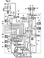
- Fig. 2 shows a known embodiment of the electrohydraulic assembly 20, wherein only the essential components of the electrohydraulic assembly will be explained below.
- Fig. 2 generates a pump 30 in a line 32 and in a guided through a pilot control valve 36 line 38, a system pressure from which by means of the pilot pressure control valve 36 in a line 52, a pilot pressure is derived.
- the system pressure line 38 is connected to an input of a pressure control valve 40 having a return outlet and a control port.
- a cooling line 42 is connected, which leads to a radiator 44, whose outlet is connected to a return line 46.
- a bypass line 48 connects the cooling line 42 upstream of the radiator 44 with the return line 46.
- a pressure limiting valve 50 is arranged, which opens increasingly when the pressure in the cooling line 42 exceeds the pressure in the return line 46.
- the control port of the pressure control valve 40 is connected to a line 53, from which a line branches off to a control pressure valve 54, which is preferably designed as an electromagnetically actuated proportional valve and the line 53 connects according to its operation with a return.
- the line 53 is connected via a throttle 56 to the pilot pressure line 52. With the help of the control valve 54, the system pressure is adjusted via the pressure control valve 40.
- pilot pressure line 52 From the pilot pressure line 52 branch off different lines which are connected with the interposition of throttles 56 respectively with inputs of control valves 58, 60 and 62 and open into control chambers of slide valves 64, 66 and 68 1 and 68 2 .
- the control valve 58 is preferably designed as an electromagnetically actuated proportional valve.
- the control valves 60 and 62 are preferably simple switching valves. By means of the control valves, the pilot pressure line 52 can be connected in each case in accordance with the released from the control valves cross-section with a return, so that the pressure in the respective control chamber decreases.
- the slide valves each contain a slide, which is acted upon at one end face with hydraulic control pressure and works on the other end face against a spring.
- the slide housing has inlets and outlets, wherein depending on the position of the slide, an inlet is connected to one of two outlets associated therewith.
- the slide valve 64 has two outlets, of which the left is pressurized with unpressurized control chamber with the system pressure prevailing in the line 32 and the right is acted upon at a correspondingly high control pressure applied control chamber with the system pressure. It is understood that the of the slide valve each forwarded pressure depends on the level of the control pressure.
- the two outlets of the spool valve 64 are connected to two inlets of the spool valve 66, which has four outlets, of which the two left are connected to inlets of the spool valve 68 1 and the two right are connected to inlets of the spool valve 68 2 .
- the spool valves 68 1 and 68 2 have four outlets, of which the left two are associated with the left inlet and the two right are associated with the right inlet.
- the total of eight outlets of the slide valves 68 1 and 68 2 are connected to adjusting cylinders SZ1 to SZ8, with which gears of the dual-clutch transmission ( Fig. 1 ).
- the slide valves are thus arranged cascade-like in three stages one behind the other, wherein the slide valve 64, the first stage, the slide valve 66, the second stage and the slide valves 68 1 and 68 2 form the third stage. It is understood that the slide valves 68 1 and 68 2 could be combined to form a slide valve, which would have to be designed to be correspondingly long, or that the slide valves 66 and 68 could each be formed by two slide valves corresponding to the slide valve 64.
- each of the actuating cylinders SZ1 to SZ8 selectively pressurized. If, for example, the actuating cylinder SZ1 is to be pressurized, all the control valves must be closed, so that the control chambers of all slide valves are pressurized.
- the shift cylinder SZ7 for example, is pressurized with system pressure when the control chamber of the spool valve 64 is depressurized, the control chamber of the spool valve 66 is depressurized and the control chamber of the spool valve 68 1 is pressurized.
- the function of the pressure relief valve 50 is as follows:
- the pressure relief valve 50 opens so that a part of the hydraulic fluid flows around the radiator 44 through the bypass passage 48. Since the flow resistance of the radiator 44 is temperature-dependent on account of the viscosity of the hydraulic fluid, the cooling fluid of the hydraulic fluid is automatically supplied as required. With cold hydraulic fluid, the back pressure across the radiator is high. As a result, the pressure relief valve 50 opens even at low flow through the radiator. With hot hydraulic fluid, however, with a stronger Cooling of the hydraulic fluid is necessary, the back pressure across the cooler is lower, so that the pressure relief valve 50 opens only at higher flow rates through the radiator. With the help of the pressure limiting valve 50, a demand-adapted cooling of the hydraulic fluid is thus achieved.
- the clutches K1 and K2 are controlled via a common pilot spool valve 70 whose position is controlled by means of an electromagnetic control valve 72 designed as a proportional valve.
- the pressurization of the actuating cylinders 14 and 16 of the clutches K1 and K2 is effected individually via these associated slide valves 74 and 76, through the pilot spool valve 70, wherein the position of the spool valves 74 and 76 via electromagnetic, designed as proportional valves control valves 78 and 80 takes place.
- the control of the clutches is known per se and is therefore not explained in detail.
- Fig. 2 how out Fig. 2 can be seen, with all the control valves prevailing in the pilot pressure line 52 control pressure either placed directly on the control chambers of the controlled slide valves or the control chamber is relieved of pressure by opening the respective control valve, wherein between the pilot pressure line 52 and the respective connecting line between the control chamber of the slide valve 74 and 76 and the control valve 78 and 80, a throttle is arranged.
- the hydraulic fluid flowing through the return line 46 does not directly flow back into a reservoir, but the fluid flowing out of an outlet 82 of the return line is used to cool the clutches.
- Fig. 2 is indicated by the Strichtician mich a housing in which the individual line paths are formed and in or on which the respective valves are arranged.
- the electromagnets of the control valves are in accordance with the outputs of the control device 24.
- Fig. 1 connected. Lead out of the housing or the module assembly lines (output lines 22 of Fig. 1 ) to the clutches, the radiator, the shift cylinders and to cool the clutches out.
- a conduit leading from a hydraulic fluid reservoir leads to the pump 30, which is mounted as a separate assembly on the housing.
- the device described can be modified in many ways.
- the pressure control valve 40 is advantageously located in the immediate vicinity of the pump.
- the slide valves may be designed such that their respective non-pressurized outlet to a Return is open.
- the pilot pressure relief valve can be omitted if you are working without pilot control.
- Fig. 3 shows one opposite the Fig. 2 modified embodiment of the hydraulic system.
- the main change is the elimination of the control valve 60 and in the control of the control chamber of the spool valve 66 directly to the clutch K1 supplied hydraulic pressure.
- each of the two partial transmissions is assigned one of the clutches K1 and K2. For example, while driving in a straight gear, the next or previous odd gear is preselected. This happens while the clutch of the sub-transmission is closed with the even gears. Similarly, when driving in an odd gear one of the even gears is preselected.
- the clutch K1 is the clutch associated with the straight gears, ie the clutch K1 is closed when driving in a straight gear, then only one of the odd gears can be preselected when the clutch K1 is closed, ie one of the associated shift cylinders is actuated. If, as in Fig. 3 shown, the clutch K1 supplied hydraulic fluid pressure of the control chamber of the spool valve 66 is supplied, is the slide in the right position, so that only the two respective right-hand outlets of the spool valves 68 1 and 68 2 depending on the pressurization of the control chambers of the spool valves 64 and 68 first and 68 2 are selectively pressurized.
- shift cylinder SZ1, SZ2 or SZ5, SZ6 can be actuated.
- These shift cylinders are assigned to the gear part with odd gears.
- one of the other shift cylinder can be actuated when the clutch K1 is depressurized.
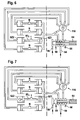
- Fig. 4 which shows a hydraulic concept of the device according to the invention, are four switching assemblies 90 1 to 90 4 to switch, each having two counteracting shift cylinder SZ1 to SZ8.
- Each switch assembly 90 includes a shift fork 92, which is advantageously displaceable from a middle neutral position to the left and to the right.
- FIG. 4 shows an embodiment of a control mode for controlling the gear sharing.
- a 4/3-way valve is provided for controlling the shift cylinder, the first slide valve 64 of the Figures 2 and 3 equivalent.
- the slide valve 64 has an input 94 which can be acted upon by system pressure, a control input 96 which can be acted upon by control pressure, a return output 98 and two outputs 100 and 102, which are connected to the system pressure input 94 or the return output 98 depending on the pressurization of the control input 96.
- the two outputs 100 and 102 of the first slide valve 64 are connected to a 6/4-way valve 104, the outputs 106, 108, 110 and 112 are connected to the switching cylinders SZ5, SZ6, SZ7 and SZ8.
- Another output of the 6/4-way valve 104, which simultaneously forms the input 100, is connected as a common output together with the switching cylinders SZ1, SZ2, SZ3 and SZ4.
- the structure of the 6/4-way valve 104 is such that it switches the system pressure either on one of the shift cylinder SZ5, SZ6, SZ7 and SZ8, so that then the corresponding shift fork is shifted to the left, or the system pressure switches to seven shift cylinder and the eighth switching cylinder with the return outlet 98 connects. The associated shift fork is then shifted to the right.
- An advantage of the illustrated concept lies in the small number of solenoid valves (in the example shown 5) and in the ability to control the eight shift cylinders, each of which actuate a shift fork in the example shown, with only five pressure ports.
- Fig. 5 shows a suitable as a 6/4-way valve, simple in construction, generally designated 116 rotary valve in four different positions.
- the rotary valve 116 has a housing 118, within which a rotary valve 120 is rotatably arranged.
- the housing further has a total of six ports, of which the appropriate Fig. 5 the upper four correspond to the outputs 106, 108, 110 and 112, another output to the output 100 of the slide valve 64 of the Fig. 4 connected input or collecting output 122 corresponds, and another port forms an input 124 which communicates with the output 102 of the slide valve 64 of the Fig. 4 connected is.
- the rotary valve 120 is in the in Fig. 5 shown rotatably in which it selectively connects the input 124 to one of the outputs 106, 108, 110 and 112.
- P1 is in Fig. 5
- P2 a pressure level corresponding to the system pressure
- P2 a largely pressureless, connected to the return port 98, printing state
- the pressure level P2 does not have to be zero; It is important that the two pressure levels are different.
- FIGS. 6 and 7 represent the described conditions by way of example.
- a rotary valve such as a 6/4-way valve forming rotary valve 116, for example, by means of a stepper motor easily operable, the respective end positions (positions 1 and 4 of Fig. 5 ) Can be stop positions and the intermediate positions are controlled or controlled approached and advantageously monitored.
- position or displacement sensors for adjusting positions 2 and 3 can be avoided.
- Another way to rotate the rotary valve 120 consists in the combination of a solenoid valve with an axial slide.
- Fig. 8 shows one of the representations of Fig. 2
- the rotary valve 116 controlled by a stepper motor 126 instead of the spool valves 66 and 68, enters the Fig. 3 ,
- the friction surfaces of a dual-clutch transmission can be cooled by means of a coolant flow, wherein the coolant flow can consist of a pressurized portion and a sucked by means of a jet pump from the sump portion.
- a jet pump 83 is shown schematically, which is fed by a pressure inflow 84 and coolant via an outlet 82 and corresponding leads to the friction linings of the clutches K1 and K2 is conveyed, depending on the adjustable volume flow through the supply line 84 against the action of the check valve 85 additional coolant from the sump 86 is sucked.
- the adjustment of the volume flow via the supply line 84 can be effected depending on the friction power of the clutches K1, K2.
- a parameter for determining the friction power for example, the slip of the clutches, the transmitted torque, the temperature of the coolant flowing back from the clutches and the like can be used.
Landscapes
- Engineering & Computer Science (AREA)
- General Engineering & Computer Science (AREA)
- Mechanical Engineering (AREA)
- Physics & Mathematics (AREA)
- Fluid Mechanics (AREA)
- Gear-Shifting Mechanisms (AREA)
- Control Of Transmission Device (AREA)
- Hydraulic Clutches, Magnetic Clutches, Fluid Clutches, And Fluid Joints (AREA)
Description
- Die Erfindung betrifft eine Vorrichtung zum Ansteuern einer Mehrzahl von hydraulischen Schaltzylindern, insbesondere Schaltzylindern zum Schalten von Gängen eines Doppelkupplungsgetriebes. Die Erfindung betrifft weiter ein Hydraulikversorgungssystem für ein Doppelkupplungsgetriebe, enthaltend eine solche Vorrichtung.
- Aus der
DE 101 439 29 A1 ist eine elektrohydraulische Getriebesteuervorrichtung bekannt, mit der an Kupplungen, Bremsen und/oder Schaltmechanismen eines Automatgetriebes vorhandene Schaltzylinder mit Hydraulikdruck beaufschlagt werden können. Die Bauteile der Getriebesteuervorrichtung sind an einem Modulkörper befestigt, in dem Strömungspfade gebildet sind. An dem Modulkörper angebrachte, beispielsweise als Schieberventile ausgebildete Steuerventile steuern Hydraulikflüssigkeit durch die Strömungspfade. Die Steuerventile werden von Magnetsteuerrrentilen gesteuert, die ebenfalls am Modulkörper angebracht sind. - Der Aufbau solcher Getriebesteuervorrichtungen ist verhältnismäßig kompliziert. Insbesondere sind zur Ansteuerung der Stellzylinder eine Vielzahl von Steuer- bzw. Schieberventilen und beispielsweise elektromagnetisch betätigter Steuereinrichtungen erforderlich.
- Die
JP 08109905 A - Die gattungsbildende
DE 44 32 850 C1 zeigt eine Anordnung zum Steuern eines Gangwechselgetriebes, bei dem zwei hydraulische Stellglieder wechselweise mittels eines einzigen elektromagnetischen Steuerventils in zwei stationäre und zwei instationäre Schaltzustände schaltbar sind. - Die
DE 101 25 172 A1 zeigt eine hydraulische Schaltsteuervorrichtung für ein mehrgängiges Zahnräderwechseigetriebe, bei dem zwei parallel geschaltete Schieberventile jeweils wechselweise eine Druckkammer eines von einem Schaltventil freigeschalteten Schaltzylinders mit Systemdruck versorgen. - Die nicht vorveröffentlichte
EP 1 420 185 A2 zeigt einen Kraftfahrzeug-Antriebsstrang mit einer Getriebesteuerung, bei der mehrere hydraulische Schaltzylinder zum Schalten von Gängen von einem ersten Schieberventil mit einem Eingang mit Systemdruck, zwei Ausgängen zu den Schieberventilen und einem Rücklaufausgang versorgt werden, wobei die beiden Ausgänge wahlweise mit Systemdruck oder mit dem Rücklauf verbindbar sind. - Der Erfindung liegt die Aufgabe zugrunde, eine in ihrem Aufbau einfache Vorrichtung zum Ansteuern einer Mehrzahl von hydraulischen Schaltzylindern zu schaffen, insbesondere zur Ansteuerung von Schaltzylindern zum Schalten von Gängen eines Doppelkupplungsgetriebes.
- Eine bekannte Vorrichtung zum Ansteuern einer Mehrzahl von hydraulischen Schaltzylindem, insbesondere Schaltzylindern zum Schalten von Gängen eines Doppelkupplungsgetriebes enthält: ein erstes Schieberventil mit einem mit Steuerdruck beaufschlagbaren Steuereingang, einem mit Systemdruck beaufschlagbaren Systemdruckeingang, zwei Ausgängen und wenigstens einem Rücklaufausgang, wobei in Abhängigkeit von dem am Steuereingang liegenden Druck wahlweise der eine Ausgang mit dem Systemdruckeingang und der andere Ausgang mit dem Rücklaufausgang verbunden ist, und eine an die Ausgänge des Schieberventils angeschlossene Ventileinrichtung, mittels der die Schaltzylinder selektiv betätigbar sind.
- Durch das erste Schieberventil, das im Allgemeinen als ein 4/3-Wegeventil ausgebildet ist, und der an dieses Schieberventil angeschlossenen Ventileinrichtung werden unterschiedliche einfache Möglichkeiten zum Aufbau der erfindungsgemäßen Vorrichtung eröffnet.
- Bei einer Ausführungsform der Vorrichtung ist die Ventileinrichtung durch Schieberventile gebildet mit Eingängen und Ausgängen und Schiebern, die abhängig von einer Beaufschlagung mit Steuerdruck in eine erste oder zweite Stellung bewegbar sind, wobei jedem Eingang eines Schieberventils zwei Ausgänge zugeordnet sind, deren einer in der ersten Stellung des Schiebers und deren anderer in der zweiten Stellung des Schiebers mit dem Eingang verbunden ist, welche Schieberventile in Stufen zu einer Kaskade derart hintereinander angeordnet sind, dass ein Eingang eines Schieberventils einer nachgeordneten Stufe mit einem Ausgang eines Schieberventils der vorhergehenden Stufe verbunden ist, wobei das erste Schieberventil die erste Stufe bildet und die Ausgänge der Schieberventile der letzten Stufe mit je einem Schaltzylinder verbunden sind, und Steuereinrichtungen vorgesehen sind, von denen je eine den Schieberventilen einer Stufe zugeordnet ist, so dass alle Schieberventile einer Stufe gleichzeitig mit Steuerdruck beaufschlagbar sind.
- Damit wird erreicht, dass nicht jedem Schaltzylinder eine eigene Steuereinrichtung zugeordnet sein muss, so dass mit einer Anzahl von Steuereinrichtungen, die lediglich der Anzahl von Stufen entspricht, selektiv jeweils einer der hydraulischen Schaltzylinder schalt- bzw. betätigbar ist, deren Anzahl größer als die der Steuereinrichtungen ist.
- Dadurch enthält die zweite Stufe der Kaskade ein Schieberventil mit zwei Eingängen und vier Ausgängen und eine dritte Stufe zwei Schieberventile mit je zwei Eingängen und vier Ausgängen usw. Auf diese Weise lassen sich mit n Steuereinrichtungen 2" Schaltzylinder selektiv betätigen.
- Bei einer Vorrichtung zum Ansteuern einer Mehrzahl von hydraulischen Schaltzylindern zum Schalten von Gängen eines Doppelkupplungsgetriebes sind die mit dem einen Eingang des Schieberventils der zweiten Stufe verbindbaren Ausgänge der dritten Stufe mit Schaltzylindern verbunden, mit denen eine erste Gruppe von Gängen des Doppelkupplungsgetriebes schaltbar ist, und sind die mit dem anderen Eingang des Schieberventils der zweiten Stufe verbindbaren Ausgänge der dritten Stufe mit Schaltzylindern verbunden, mit denen eine zweite Gruppe von Gängen schaltbar ist.
- Bei einer Ausführungsform der vorgenannten Vorrichtung ist die Steuereinrichtung zum Betätigen des Schieberventils der zweiten Stufe durch einen Anschluss einer Steuerkammer des Schieberventils an eine Hydraulikleitung gebildet, über die eine der Kupplungen des Doppelkupplungsgetriebes durch Druckbeaufschlagung betätigbar ist.
- Bei einer erfindungsgemäßen Ausführungsform der Vorrichtung sind je zwei Schaltzylinder gegensinnig wirkend zu einer Schaltbaugruppe für ein Schaltglied zusammengefasst, enthält die Ventileinrichtung ein mit Steuerdruck beaufschlagbares Mehrwegeventil mit je einem der Schaltzylinder einer Schaltbaugruppe zugeordneten Einzelausgängen und einem der jeweils anderen der Schaltzylinder der Betätigungsbaugruppen gemeinsam zugeordneten Sammelausgang, und das Mehrwegventil leitet je nach Stellung des ersten Schieberventils den Systemdruck selektiv auf einen der Einzelausgänge und verbindet dabei alle anderen Schaltzylinder mit dem Rücklaufausgang oder verbindet selektiv einen der Einzelausgänge mit dem Rücklaufausgang und beaufschlagt dabei alle anderen Ausgänge mit dem Systemdruck.
- Vorteilhaft sind wenigstens einige der Steuereinrichtungen durch elektromagnetisch betätigbare Steuerventile gebildet.
- Dabei ist bevorzugt eine Vorsteuerdruckleitung über eine Drossel mit einer Verbindungsleitung zwischen einem Steuerventil und einer Steuerkammer eines Schieberventils verbunden.
- Vorteilhafterweise enthält die vorgenannte Ventileinrichtung ein Drehschieberventil, dessen Drehschieber selektiv einen mit einem Ausgang des ersten Schieberventils verbundenen Eingang mit einem der Einzelausgänge verbindet und dessen Sammelausgang gleichzeitig den anderen, mit dem anderen Ausgang des ersten Schieberventils verbundenen Eingang des Drehschieberventils bildet.
- Ein Hydraulikversorgungssystem für ein Doppelkupplungsgetriebe mit einer Vorrichtung der vorgenannten Art enthält eine von einer Pumpe mit Druck beaufschlagbare Leitung, die an ein Druckregelventil angeschlossen ist, das einen Steuerdruckanschluss zum Anschluss einer mit den Steuereinrichtungen verbundenen Steuerdruckleitung und einen Rücklaufanschluss aufweist, der über eine durch einen Kühler führende Kühlleitung mit einer Rücklaufleitung verbunden ist, eine Bypassleitung, die die Kühlleitung mit der Rücklaufleitung verbindet, und ein in der Bypassleitung angeordnetes Druckbegrenzungsventil, das den Durchströmquerschnitt der Bypassleitung bei zunehmendem Staudruck am Kühler zunehmend öffnet.
- Mit Vorteil wird zumindest ein Teil des durch die Rücklaufleitung strömenden Hydraulikfluids zur Kühlung der Kupplungen verwendet.
- Die Erfindung ist überall einsetzbar, wo eine Mehrzahl von selektiv ansteuerbaren Schaltzylindern, Hydraulikventilen usw. benötigt wird, um den Betrieb nachgeordneter Einheiten zu steuern.
- Die Erfindung wird im folgenden anhand schematischer Zeichnungen beispielsweise und mit weiteren Einzelheiten erläutert.
- In den Figuren stellen dar:
-
Fig. 1 eine Prinzipsskizze eines Doppelkupplungsgetriebes mit Steuereinrichtung, -
Fig. 2 einen Schaltplan eines Hydrauliksystems zur Betätigung eines Doppelkupplungsgetriebes, -
Fig. 3 einen Schaltplan eines Hydrauliksystems zur Betätigung zur Betätigung eines Doppelkupplungsgetriebes, -
Fig. 4 einen Hydraulikplan einer abgeänderten Ausführungsform einer erfindungsgemäßen Vorrichtung, -
Fig. 5 ein Drehventil in vier verschiedenen Stellungen, -
Fig. 6 einen ersten Zustand von Schaltbaugruppen unter Ansteuerung mit dem Drehventil gemäßFig. 5 , -
Fig. 7 einen gegenüber derFig. 6 abgeänderten Schaltzustand des Systems, und -
Fig. 8 eine derFig. 2 entsprechende Darstellung eines Schaltplans unter Verwendung des Drehventils. - Gemäß
Fig. 1 weist ein Doppelkupplungsgetriebe eine beispielsweise von einer Brennkraftmaschine angetriebene Antriebswelle 6 auf, die mit zwei Eingangswellen 8 und 10 drehfest verbunden ist. Der Drehmomentfluss von der Antriebswelle 6 in die Eingangswellen 8 und 10 ist über je eine Kupplung K1 und K2 wahlweise steuerbar. Zwischen der Eingangswelle 8 und einer Ausgangswelle 12 sind über Radpaarungen, von denen nur eine dargestellt ist, verschiedene Übersetzungen schaltbar. Ebenso sind zwischen der Eingangswelle 10 und der Ausgangswelle 12 verschiedene Radpaarungen schaltbar, von denen nur eine dargestellt ist. Zum Betätigen der Kupplungen K1 und K2 sind Stellzylinder 14 und 16 vorgesehen. Zum Schalten der Radpaarungen, beispielsweise zum Herstellen einer drehfesten Verbindung zwischen dem auf der Eingangswelle 8 oder 10 angeordneten Rad mit der jeweiligen Eingangswelle 8 oder 10, das mit einem jeweiligen, mit der Ausgangswelle ständig drehfest verbundenen Rad kämmt, sind Stellzylinder SZ1 und SZ2 vorgesehen. - Die auf der Eingangswelle 8 angeordneten Räder sind beispielsweise Räder, mit denen jeweils ein gerader Gang sowie ein Rückwärtsgang geschaltet wird. Mit der Eingangswelle 10 sind Räder verbunden, mit denen jeweils ein ungerader Gang geschaltet wird. Somit besteht das Doppelkupplungsgetriebe aus zwei insgesamt mit 17 und 18 bezeichneten Teilgetrieben, die mit einer gemeinsamen Ausgangswelle 12 arbeiten und von denen das eine beispielsweise die geraden Gänge und den Rückwärtsgang und das andere die ungeraden Gänge enthält.
- Aufbau und Funktion eines solchen Doppelkupplungsgetriebes sind an sich bekannt und werden daher nicht erläutert.
- Zur Ansteuerung der Stell- und Schaltzylinder dient eine Elektrohydraulikbaugruppe 20, die eine Hydraulikdruckversorgung, Hydraulikleitungen, Ventile zum Schalten der Leitungen und elektrisch betätigbare Ventile enthält.
- Hydraulische Ausgangsleitungen 22 der Elektrohydraulikbaugruppe 20 sind mit den Stellzylindern verbunden. Elektrische Eingänge der Elektrohydraulikbaugruppe, die mit Magneten von Magnetventilen verbunden sind, sind mit Ausgängen einer elektronischen Steuereinrichtung 24 verbunden, deren Eingänge 26 mit Sensoren verbunden sind, deren Ausgangssignale die Betätigung des Doppelkupplungsgetriebes entsprechend vorbestimmten, in der Steuereinrichtung 24 gespeicherten Programmen bestimmen.
-
Fig. 2 zeigt eine bekannte Ausführungsform der Elektrohydraulikbaugruppe 20, wobei nachfolgend nur die wesentlichen Komponenten der Elektrohydraulikbaugruppe erläutert werden. - Gemäß
Fig. 2 erzeugt eine Pumpe 30 in einer Leitung 32 und in einer durch ein Vorsteuerdruckventil 36 geführten Leitung 38 einen Systemdruck, aus dem mittels des Vorsteuerdruckventils 36 in einer Leitung 52 ein Vorsteuerdruck hergeleitet wird. Die Systemdruckleitung 38 ist mit einem Eingang eines Druckregelventils 40 verbunden, das einen Rücklaufauslass und einen Steueranschluss aufweist. An den Rücklaufauslass ist eine Kühlleitung 42 angeschlossen, die zu einem Kühler 44 führt, dessen Auslass an eine Rücklaufleitung 46 angeschlossen ist. Eine Bypassleitung 48 verbindet die Kühlleitung 42 strömungsoberhalb des Kühlers 44 mit der Rücklaufleitung 46. In der Bypassleitung 48 ist ein Druckbegrenzungsventil 50 angeordnet, das zunehmend öffnet, wenn der Druck in der Kühlleitung 42 den Druck in der Rücklaufleitung 46 übersteigt. - Der Steueranschluss des Druckregelventils 40 ist mit einer Leitung 53 verbunden, von der eine Leitung zu einem Steuerdruckventil 54 abzweigt, das bevorzugt als elektromagnetisch betätigtes Proportionalventil ausgebildet ist und die Leitung 53 entsprechend seiner Betätigung mit einem Rücklauf verbindet. Die Leitung 53 ist über eine Drossel 56 mit der Vorsteuerdruckleitung 52 verbunden. Mit Hilfe des Steuerventils 54 wird über das Druckregelventil 40 der Systemdruck eingestellt.
- Von der Vorsteuerdruckleitung 52 zweigen verschiedene Leitungen ab, die unter Zwischenanordnung von Drosseln 56 jeweils mit Eingängen von Steuerventilen 58, 60 und 62 verbunden sind und in Steuerkammern von Schieberventilen 64, 66 und 681 und 682 münden.
- Das Steuerventil 58 ist vorzugsweise als elektromagnetisch betätigtes Proportionalventil ausgebildet. Die Steuerventile 60 und 62 sind bevorzugt einfache Schaltventile. Mittels der Steuerventile ist die Vorsteuerdruckleitung 52 jeweils entsprechend dem von den Steuerventilen freigegebenen Querschnitt mit einem Rücklauf verbindbar, so dass der Druck in der jeweiligen Steuerkammer absinkt.
- Die Schieberventile enthalten jeweils einen Schieber, der an einer Stirnseite mit hydraulischem Steuerdruck beaufschlagt ist und an der anderen Stirnseite gegen eine Feder arbeitet. Das Schiebergehäuse weist jeweils Einlässe und Auslässe auf, wobei je nach Stellung des Schiebers ein Einlass mit einem von zwei ihm zugeordneten Auslässen verbunden ist. Wie aus der
Fig. 2 ersichtlich, weist das Schieberventil 64 zwei Auslässe auf, von denen der linke bei druckloser Steuerkammer mit dem in der Leitung 32 herrschenden Systemdruck beaufschlagt wird und der rechte bei mit entsprechend hohem Steuerdruck beaufschlagter Steuerkammer mit dem Systemdruck beaufschlagt ist. Es versteht sich, dass der von dem Schieberventil jeweils weiter geleitete Druck von der Höhe des Steuerdrucks abhängt. Die beiden Auslässe des Schieberventils 64 sind mit zwei Einlässen des Schieberventils 66 verbunden, das vier Auslässe hat, von denen die beiden linken mit Einlässen des Schieberventils 681 verbunden sind und die beiden rechten mit Einlässen des Schieberventils 682 verbunden sind. Die Schieberventile 681 und 682 haben vier Auslässe, von denen die jeweils beiden linken mit dem linken Einlass und die beiden rechten dem rechten Einlass zugeordnet sind. Die insgesamt acht Auslässe der Schieberventile 681 und 682 sind mit Stellzylindern SZ1 bis SZ8 verbunden, mit denen Gänge des Doppelkupplungsgetriebes (Fig. 1 ) geschaltet werden. - Die Schieberventile sind somit kaskadenartig in drei Stufen hintereinander angeordnet, wobei das Schieberventil 64 die erste Stufe, das Schieberventil 66 die zweite Stufe und die Schieberventile 681 und 682 die dritte Stufe bilden. Es versteht sich, dass die Schieberventile 681 und 682 zu einem Schieberventil zusammengefasst sein könnten, das entsprechend lang gestaltet sein müsste, oder dass die Schieberventile 66 und 68 durch jeweils zwei dem Schieberventil 64 entsprechende Schieberventile gebildet sein könnten.
- Wie ohne weiteres verständlich, ist durch entsprechende Betätigung der Steuerventile 58, 60 und 62 jeder einzelne der Stellzylinder SZ1 bis SZ8 selektiv mit Druck beaufschlagbar. Wenn beispielsweise der Stellzylinder SZ1 mit Druck beaufschlagt werden soll, müssen alle Steuerventile geschlossen sein, so dass die Steuerkammern aller Schieberventile druckbeaufschlagt sind. Der Schaltzylinder SZ7 beispielsweise wird mit Systemdruck beaufschlagt, wenn die Steuerkammer des Schieberventils 64 drucklos ist, die Steuerkammer des Schieberventils 66 drucklos ist und die Steuerkammer des Schieberventils 681 mit Druck beaufschlagt ist.
- Mit der beschriebenen Anordnung ist es somit möglich, mit lediglich drei Steuerventilen 58, 60 und 62 acht Stellzylinder selektiv anzusteuern.
- Die Funktion des Druckbegrenzungsventils 50 ist folgende:
- Wenn der Durchströmwiderstand des Kühlers 44 einen vorbestimmten Wert übersteigt, öffnet das Druckbegrenzungsventil 50, so dass ein Teil des Hydraulikfluids den Kühler 44 durch die Bypassleitung 48 hindurch umströmt. Da der Durchströmwiderstand des Kühlers 44 aufgrund der Viskosität des Hydraulikfluids temperaturabhängig ist, ergibt sich selbsttätig eine bedarfsangepasste Kühlung des Hydraulikfluids. Bei kaltem Hydraulikfluid ist der Rückstaudruck über den Kühler hoch. Dadurch öffnet das Druckbegrenzungsventil 50 bereits bei geringer Volumenströmung durch den Kühler. Bei heißem Hydraulikfluid dagegen, bei dem eine stärkere Kühlung des Hydraulikfluids notwendig ist, ist der Rückstaudruck über den Kühler geringer, so dass das Druckbegrenzungsventil 50 erst bei höheren Volumenströmen durch den Kühler öffnet. Mit Hilfe des Druckbegrenzungsventils 50 wird somit eine bedarfsangepasste Kühlung des Hydraulikfluids erreicht.
- Die Kupplungen K1 und K2 werden über ein gemeinsames Vorsteuerschieberventil 70 angesteuert, dessen Stellung mittels eines als Proportionalventil ausgebildeten elektromagnetischen Steuerventils 72 gesteuert wird. Die Druckbeaufschlagung der Stellzylinder 14 und 16 der Kupplungen K1 und K2 erfolgt einzeln über diesen zugeordnete Schieberventile 74 und 76, durch das Vorsteuerschieberventil 70 hindurch, wobei die Stellung der Schieberventile 74 und 76 über elektromagnetische, als Proportionalventile ausgebildete Steuerventile 78 und 80 erfolgt. Die Ansteuerung der Kupplungen ist an sich bekannt und wird daher nicht im einzelnen erläutert.
- Wie aus
Fig. 2 weiter ersichtlich, wird mit allen Steuerventilen der in der Vorsteuerdruckleitung 52 herrschende Steuerdruck entweder unmittelbar auf die Steuerkammern der angesteuerten Schieberventile gelegt oder die Steuerkammer wird durch Öffnung des jeweiligen Steuerventils druckentlastet, wobei zwischen der Vorsteuerdruckleitung 52 und der jeweiligen Verbindungsleitung zwischen der Steuerkammer des Schieberventils 74 und 76 und dem Steuerventil 78 und 80eine Drossel angeordnet ist. Vorteilhaft strömt das durch die Rücklaufleitung 46 strömende Hydraulikfluid nicht unmittelbar in einen Vorratsbehälter zurück, sondern das aus einem Auslass 82 der Rücklaufleitung ausströmende Fluid wird zur Kühlung der Kupplungen verwendet. - In
Fig. 2 ist durch die Strichpunktierung ein Gehäuse angedeutet, in dem die einzelnen Leitungspfade ausgebildet sind und in oder an dem die jeweiligen Ventile angeordnet sind. Die Elektromagnete der Steuerventile sind mit den Ausgängen der Steuereinrichtung 24 gem.
Fig. 1 verbunden. Aus dem Gehäuse bzw. der Modulbaugruppe führen Leitungen (Ausgangsleitungen 22 derFig. 1 ) zu den Kupplungen, dem Kühler, den Schaltzylindern und zur Kühlung der Kupplungen heraus. Eine aus einem Hydraulikfluidvorratsbehälter führende Leitung führt zu der Pumpe 30, die als gesonderte Baugruppe an dem Gehäuse angebracht ist. - Die beschriebene Vorrichtung kann in vielfältiger Weise abgeändert werden. Das Druckregelventil 40 befindet sich vorteilhaft in unmittelbarer Nähe der Pumpe. Die Schieberventile können derart ausgebildet sein, dass ihr jeweiliger nicht mit Druck beaufschlagter Auslass zu einem Rücklauf hin offen ist. Das Vorsteuerdruckventil kann entfallen, wenn ohne Vorsteuerung gearbeitet wird.
-
Fig. 3 zeigt eine gegenüber derFig. 2 abgeänderte Ausführungsform des Hydrauliksystems. Die wesentliche Änderung liegt im Entfall des Steuerventils 60 und in der Ansteuerung der Steuerkammer des Schieberventils 66 unmittelbar mit dem der Kupplung K1 zugeführten Hydraulikdruck. - Wie weiter oben erläutert, besteht ein Prinzip des Doppelkupplungsgetriebes (
Fig. 1 ) darin, die geraden Gänge im einem der Teilgetriebe und die ungeraden Gänge in dem anderen der Teilgetriebe zu verbauen. Jedem der beiden Teilgetriebe ist eine der Kupplungen K1 und K2 zugeordnet. Während beispielsweise in einem geraden Gang gefahren wird, wird der nächste oder vorhergehende ungerade Gang vorgewählt. Dies geschieht, während die Kupplung des Teilgetriebes mit den geraden Gängen geschlossen ist. Analog wird bei einer Fahrt in einem ungeraden Gang einer der geraden Gänge vorgewählt. - Wenn beispielsweise die Kupplung K1 die den geraden Gängen zugeordnete Kupplung ist, d.h. die Kupplung K1 geschlossen ist, wenn in einem geraden Gang gefahren wird, dann kann bei geschlossener Kupplung K1 nur einer der ungeraden Gänge vorgewählt werden, d.h. einer der zugehörigen Schaltzylinder betätigt werden. Wenn, wie in
Fig. 3 dargestellt, der Kupplung K1 zugeführte Hydraulikfluiddruck der Steuerkammer des Schieberventils 66 zugeführt wird, befindet sich dessen Schieber in der rechten Stellung, so dass nur die beiden jeweils rechten Auslässe der Schieberventile 681 und 682 je nach Druckbeaufschlagung der Steuerkammern der Schieberventile 64 und 681 sowie 682 selektiv mit Druck beaufschlagbar sind. Somit kann einer der Schaltzylinder SZ1, SZ2 oder SZ5, SZ6 betätigt werden. Diese Schaltzylinder werden dem Getriebeteil mit ungeraden Gängen zugeordnet. Umgekehrt kann einer der anderen Schaltzylinder betätigt werden, wenn die Kupplung K1 drucklos ist. - Bei der Ausführung gemäß
Fig. 3 kann somit gegenüber der derFig. 2 ein Steuerventil eingespart werden. - Anhand der
Figuren 4 bis 8 wird im Folgenden eine erfindungsgemäße Vorrichtung zum Ansteuern einer Mehrzahl von hydraulischen Schaltzylindern erläutert. Dabei werden für zu denen derFiguren 2 und3 ähnliche Bauteile die gleichen Bezugszeichen wie inFiguren 2 und3 verwendet. - Gemäß
Fig. 4 , die ein Hydraulikkonzept der erfindungsgemäßen Vorrichtung zeigt, sind vier Schaltbaugruppen 901 bis 904 zu schalten, die jeweils zwei gegensinnig wirkende Schaltzylinder SZ1 bis SZ8 aufweisen. Jede Schaltbaugruppe 90 enthält eine Schaltgabel 92, die aus einer mittleren Neutralstellung vorteilhafterweise nach links und nach rechts verschiebbar ist. -
Figur 4 zeigt eine Ausführungsform eines Steuermodus zur Steuerung der Gangbeteiligung. Hierzu ist zur Steuerung der Schaltzylinder ist ein 4/3-Wegeventil vorgesehen, das dem ersten Schieberventil 64 derFiguren 2 und3 entspricht. Das Schieberventil 64 hat einen mit Systemdruck beaufschlagbaren Eingang 94, einen mit Steuerdruck beaufschlagbaren Steuereingang 96, einen Rücklaufausgang 98 und zwei Ausgänge 100 und 102, die je nach Druckbeaufschlagung des Steuereingangs 96 mit dem Systemdruckeingang 94 oder dem Rücklaufausgang 98 verbunden sind. - Die beiden Ausgänge 100 und 102 des ersten Schieberventils 64 sind mit einem 6/4-Wegeventil 104 verbunden, dessen Ausgänge 106, 108, 110 und 112 mit den Schaltzylindern SZ5, SZ6, SZ7 und SZ8 verbunden sind. Ein weiterer Ausgang des 6/4-Wegeventils 104, der gleichzeitig den Eingang 100 bildet, ist als ein Sammelausgang gemeinsam mit den Schaltzylindern SZ1, SZ2, SZ3 und SZ4 verbunden. Somit sind im dargestellten Beispiel die gemäß
Fig. 4 nach links wirkenden Schaltzylinder mit den Einzelausgängen des 6/4-Wegeventils verbunden, wo hingegen die nach rechts wirkenden Schaltzylinder mit dem Sammelausgang verbunden sind. - Der Aufbau des 6/4-Wegeventils 104 ist derart, dass es den Systemdruck entweder auf einen der Schaltzylinder SZ5, SZ6, SZ7 und SZ8 schaltet, so dass dann die entsprechende Schaltgabel nach links verschoben wird, oder den Systemdruck auf jeweils sieben Schaltzylinder schaltet und den achten Schaltzylinder mit dem Rücklaufausgang 98 verbindet. Die zugehörige Schaltgabel wird dann nach rechts verschoben.
- Ein Vorteil des dargestellten Konzepts liegt in der geringen Anzahl von Elektromagnetventilen (im dargestellten Beispiel 5) und in der Möglichkeit, die im dargestellten Beispiel acht Schaltzylinder, von dem jeweils zwei eine Schaltgabel betätigen, mit lediglich fünf Druckanschlüssen zu steuern.
-
Fig. 5 zeigt ein als 6/4-Wegeventil geeignetes, in seinem Aufbau einfaches, insgesamt mit 116 bezeichnetes Drehschieberventil in vier unterschiedlichen Stellungen. Das Drehschieberventil 116 weist ein Gehäuse 118 auf, innerhalb dessen ein Drehschieber 120 drehbar angeordnet ist. Das Gehause weist weiter insgesamt sechs Anschlüsse auf, von denen die gemaßFig. 5 oberen vier den Ausgängen 106, 108, 110 und 112 entsprechen, ein weiterer Ausgang dem mit dem Ausgang 100 des Schieberventils 64 derFig. 4 verbundenen Eingang bzw. Sammelausgang 122 entspricht, und ein weiterer Anschluss einen Eingang 124 bildet, der mit dem Ausgang 102 des Schieberventils 64 derFig. 4 verbunden ist. - Der Drehschieber 120 ist in die in
Fig. 5 dargestellten vier unterschiedlichen Stellungen drehbar, in denen er den Eingang 124 selektiv mit einem der Ausgänge 106, 108, 110 und 112 verbindet. Mit P1 ist inFig. 5 beispielsweise ein dem Systemdruck entsprechendes Druckniveau bezeichnet, mit P2 ist ein weitgehend druckloser, mit dem Rücklaufanschluss 98 verbundener, Druckzustand bezeichnet. Das Druckniveau P2 muss nicht Null sein; wichtig ist, dass die beiden Druckniveaus verschieden sind. - Wie unmittelbar ersichtlich, ist in den vier dargestellten Stellungen jeweils einer der Schaltzylinder SZ5 bis SZ8 (
Fig. 4 ) mit dem Systemdruck P1 beaufschlagt, wo hingegen jeweils alle anderen sieben Schaltzylinder mit dem im dargestellten Beispiel niedrigeren Druck P2 beaufschlagt sind bzw. drucklos sind. - Wenn durch Umschalten des Schieberventils 64 der Eingang 124 mit dem Rücklaufausgang 98 verbunden ist und der Eingang 122 mit dem Systemdruck beaufschlagt ist, kehren sich die Verhältnisse um; jeweils einer der Schaltzylinder SZ5 bis SZ8 ist mit niederem Druck beaufschlagt, wo hingegen alle anderen Schaltzylinder mit Systemdruck beaufschlagt sind.
- Die
Figuren 6 und 7 stellen die geschilderten Verhältnisse beispielhaft dar. - Im dargestellten Beispiel ist in den Stellungen gemäß
Fig. 6 der Schaltzylinder 2 mit Systemdruck beaufschlagt, wo hingegen alle anderen Schaltzylinder drucklos sind. Dies führt dazu, dass im dargestellten Beispiel der Schaltzylinder 2 die Schaltgabel 923 nach rechts bewegt, so dass im dargestellten Beispiel der erste Gang eines Doppelkupplungsgetriebes eingelegt wird. Die Schaltzylinder der anderen Betätigungsbaugruppen sind jeweils mit dem gleichen, niederen Druck beaufschlagt, so dass sich die jeweiligen Schaltgabeln in Neutralstellung befinden. - Im Zustand der
Fig. 7 ist das Schieberventil 64 umgeschaltet, so dass der Schaltzylinder SZ2 nunmehr auf niederem Druck ist und der Schaltzylinder SZ7 gemeinsam mit den restlichen Schaltzylindern sich auf Systemdruck befindet. Die Schaltgabel 923 wird zum Auslegen des ersten Ganges nach links bewegt. Die Schaltzylinder der anderen Schaltbaugruppen sind mit dem gleichen hohen Systemdruck beaufschlagt, so dass sich deren Schaltgabeln in Neutralstellung befinden. - Ein Drehschieberventil, wie das ein 6/4-Wegeventil bildende Drehschieberventil 116, ist beispielsweise mittels eines Schrittschaltmotors einfach betätigbar, wobei die jeweiligen Endstellungen (Stellungen 1 und 4 der
Fig. 5 ) Anschlagstellungen sein können und die Zwischenstellungen gesteuert oder geregelt angefahren werden und vorteilhafterweise überwacht werden. Durch Verwendung eines Schrittmotors können zusätzlich Positions- oder Wegesensoren für die Einstellung der Stellungen 2 und 3 vermieden werden. - Eine weitere Möglichkeit, den Drehschieber 120 zu verdrehen, besteht in der Kombination eines Elektromagnetventils mit einem Axialschieber.
-
Fig. 8 zeigt einen der Darstellungen derFig. 2 entsprechenden Gesamthydraulikplan mit Verwendung des Drehschieberventils 116. Wie ersichtlich, tritt das von einem Schrittmotor 126 gesteuerte Drehschieberventil 116 anstelle der Schieberventile 66 und 68 derFig. 3 . - Gemäß einer weiteren erfinderischen Ausgestaltung können die Reibflächen eines Doppelkupplungsgetriebes mittels eines Kühlmittelstroms gekühlt werden, wobei der Kühlmittelstrom aus einem druckbeaufschlagten Anteil und einem mittels einer Strahlpumpe aus dem Sumpf angesaugten Anteil bestehen kann. Hierzu ist in den
Figuren 2 ,3 und8 eine derartige Strahlpumpe 83 schematisch dargestellt, die durch einen Druckzufluss 84 gespeist wird und Kühlmittel über einen Auslass 82 und entsprechende Zuleitungen zu den Reibbelägen der Kupplungen K1 und K2 befördert wird, wobei in Abhängigkeit von dem einstellbaren Volumenstrom über die Zuleitung 84 entgegen der Wirkung des Rückschlagventils 85 zusätzlich Kühlmittel aus dem Sumpf 86 angesaugt wird. Die Einstellung des Volumenstroms über die Zuleitung 84 kann dabei abhängig von der Reibleistung der Kupplungen K1, K2 erfolgen. Als Parameter zur Bestimmung der Reibleistung kann beispielsweise der Schlupf der Kupplungen, das übertragene Drehmoment, die Temperatur des von den Kupplungen zurückfließenden Kühlmittels und dergleichen herangezogen werden. -
- 6
- Antriebswelle
- 8
- Eingangswelle
- 10
- Eingangswelle
- 12
- Ausgangswelle
- 14
- Stellzylinder
- 16
- Stellzylinder
- 17
- Teilgetriebe
- 18
- Teilgetriebe
- 20
- Elektrohydraulikbaugruppe
- 22
- Ausgangsleitungen
- 24
- Steuereinrichtung
- 26
- Eingänge
- 30
- Pumpe
- 32
- Leitung
- 36
- Vorsteuerdruckventil
- 38
- Leitung
- 40
- Druckregelventil
- 42
- Kühlleitung
- 44
- Kühler
- 46
- Rücklaufleitung
- 48
- Bypassleitung
- 50
- Druckbegrenzungsventil
- 52
- Vorsteuerdruckleitung
- 53
- Leitung
- 54
- Steuerventil
- 56
- Drossel
- 58
- Steuerventil
- 60
- Steuerventil
- 62
- Steuerventil
- 64
- Schieberventil
- 66
- Schieberventil
- 68
- Schieberventil
- 681
- Schieberventil
- 682
- Schieberventil
- 70
- Vorsteuerschieberventil
- 72
- Steuerventil
- 74
- Schieberventil
- 76
- Steuerventil
- 78
- Steuerventil
- 80
- Steuerventil
- 82
- Auslass
- 83
- Strahlpumpe
- 84
- Zuleitung
- 85
- Rückschlagventil
- 86
- Sumpf
- 90
- Schaltbaugruppe
- 901
- Schaltbaugruppe
- 902
- Schaltbaugruppe
- 903
- Schaltbaugruppe
- 904
- Schaltbaugruppe
- 921
- Schaltgabel
- 922
- Schaltgabel
- 923
- Schaltgabel
- 924
- Schaltgabel
- 94
- Systemdruckeingang
- 96
- Steuereingang
- 98
- Rücklaufausgang
- 100
- Ausgang
- 102
- Ausgang
- 104
- 6/4-Wegeventil
- 106
- Ausgang
- 108
- Ausgang
- 110
- Ausgang
- 112
- Ausgang
- 116
- Drehschieberventil
- 118
- Gehäuse
- 120
- Drehschieber
- 122
- Ausgang zu Schaltventilen SZ5-SZ8
- 124
- Eingang
- 126
- Schrittmotor
- K1
- Kupplung
- K2
- Kupplung
- SZ1
- Schaltzylinder
- SZ2
- Schaltzylinder
- SZ3
- Schaltzylinder
- SZ4
- Schaltzylinder
- SZ5
- Schaltzylinder
- SZ6
- Schaltzylinder
- SZ7
- Schaltzylinder
- SZ8
- Schaltzylinder
- P1
- Systemdruck
- P2
- Tankdruck
Claims (7)
- Vorrichtung zum Ansteuern einer Mehrzahl von hydraulischen Schaltzylindern (SZ1-SZ8), insbesondere Schaltzylindern zum Schalten von Gängen eines Doppelkupplungsgetriebes, enthaltend ein erstes Schieberventil (64) mit einem mit Steuerdruck beaufschlagbaren Steuereingang (96), einem mit Systemdruck beaufschlagbaren Systemdruckeingang (94), zwei Ausgängen (100, 102) und wenigstens einem Rücklaufausgang (98), wobei in Abhängigkeit von dem am Steuereingang liegenden Druck wahlweise der eine Ausgang mit dem Systemdruckeingang und der andere Ausgang mit dem Rücklaufausgang verbunden ist, und eine an die Ausgänge des Schieberventils angeschlossene Ventileinrichtung (66, 68; 104; 116), mittels der die Schaltzylinder selektiv betätigbar sind, dadurch gekennzeichnet, dass je zwei Schaltzylinder gegensinnig wirkend in einer Schaltbaugruppe (90) mit je einem Schaltglied (92) zusammengefasst sind,
die Ventileinrichtung ein mit Steuerdruck beaufschlagbares Mehrwegeventil (104; 116) mit je einem der Schaltzylinder einer Schaltbaugruppe zugeordneten Einzelausgängen (106, 108, 110, 112) und einem den jeweils anderen der Schaltzylinder der Betätigungsbaugruppen gemeinsam zugeordneten Sammelausgang (122) enthält, und das Mehrwegeventil je nach Stellung des ersten Schieberventils (64) den Systemdruck selektiv auf einen der Einzelausgänge leitet und dabei alle anderen Schaltzylinder mit dem Rücklaufausgang verbindet oder selektiv einen der Einzelausgängen mit dem Rücklaufausgang verbindet und dabei alle anderen Ausgänge mit dem Systemdruck beaufschlagt. - Vorrichtung nach Anspruch 1, wobei wenigstens einige der Steuereinrichtungen durch elektromagnetisch betätigbare Steuerventile (58) gebildet sind.
- Vorrichtung nach Anspruch 2, wobei eine Vorsteuerdruckleitung (52) über eine Drossel (56) mit einer Verbindungsleitung zwischen einem Steuerventil (58) und einer Steuerkammer eines Schieberventils (64) verbunden ist.
- Vorrichtung nach Anspruch 1, wobei das Mehrwegeventil ein Drehschieberventil (116) ist, dessen Drehschieber (120) selektiv einen mit einem Ausgang des ersten Schieberventils (64) verbundenen Eingang mit einem der Einzelausgänge (106, 108, 110, 112) verbindet und dessen Sammelausgang (122) gleichzeitig den anderen, mit dem anderen Ausgang des ersten Schieberventils verbundenen Eingang des Drehschieberventils bildet.
- Hydraulikversorgungssystem für ein Doppelkupplungsgetriebe, enthaltend eine Vorrichtung nach einem der Ansprüche 1 bis 4, enthaltend
eine von einer Pumpe (30) mit Druck beaufschlagbare Leitung (38), die an ein Druckregelventil (40) angeschlossen ist, das einen Anschluss für mit der oder den Steuereinrichtungen (58, 60, 62) verbundene Vorsteuerdruckleitung (52) und einen Rücklaufanschluss aufweist, der über eine durch einen Kühler (44) führende Kühlleitung (42) mit einer Rücklaufleitung (46) verbunden ist,
eine Bypassleitung (48), die die Kühlleitung mit der Rücklaufleitung verbindet, und
ein in der Bypassleitung angeordnetes Druckbegrenzungsventil (50), das den Durchströmquerschnitt der Bypassleitung bei zunehmendem Staudruck am Kühler zunehmend öffnet. - Hydrauliksystem nach Anspruch 5, wobei zumindest ein Teil des durch die Rücklaufleitung strömenden Hydraulikfluids zur Kühlung der Kupplungen (K1, K2) verwendet wird.
- Vorrichtung nach Anspruch 6, dadurch gekennzeichnet, dass eine mit Druckmittel beaufschlagte Leitung (84) vor der Zuführung zu einem drucklosen Sumpf (86) unter Zwischenschaltung einer Strahlpumpe (83) zumindest einer Kupplung (K1, K2) zur Kühlung zugeführt wird, wobei die Strahlpumpe (83) in Abhängigkeit von dem in der Leitung (84) transportierten Volumenstrom des Druckmittel entgegen der Wirkung eines mit dem Sumpf (86) verbundenen Rückschlagventils (85) vom Sumpf (86) zusätzliches Kühlmittel zur Kühlung der zumindest einen Kupplung (K1, K2) ansaugt.
Applications Claiming Priority (6)
| Application Number | Priority Date | Filing Date | Title |
|---|---|---|---|
| DE102004024310 | 2004-05-15 | ||
| DE102004024310 | 2004-05-15 | ||
| DE102004042641 | 2004-09-03 | ||
| DE102004042641 | 2004-09-03 | ||
| DE102004062984 | 2004-12-22 | ||
| DE102004062984 | 2004-12-22 |
Publications (3)
| Publication Number | Publication Date |
|---|---|
| EP1596104A2 EP1596104A2 (de) | 2005-11-16 |
| EP1596104A3 EP1596104A3 (de) | 2007-03-14 |
| EP1596104B1 true EP1596104B1 (de) | 2009-01-21 |
Family
ID=34935806
Family Applications (1)
| Application Number | Title | Priority Date | Filing Date |
|---|---|---|---|
| EP20050009198 Not-in-force EP1596104B1 (de) | 2004-05-15 | 2005-04-27 | Vorrichtung zum Ansteuern einer Mehrzahl von hydraulischen Schaltzylindern sowie Hydraulikversorgungssystem für ein Doppelkupplungsgetriebe |
Country Status (8)
| Country | Link |
|---|---|
| US (1) | US7418885B2 (de) |
| EP (1) | EP1596104B1 (de) |
| JP (1) | JP4759676B2 (de) |
| KR (2) | KR101228712B1 (de) |
| CN (1) | CN1696542B (de) |
| AT (1) | ATE421655T1 (de) |
| BR (1) | BRPI0501826A (de) |
| DE (1) | DE502005006512D1 (de) |
Cited By (1)
| Publication number | Priority date | Publication date | Assignee | Title |
|---|---|---|---|---|
| DE102010001069A1 (de) | 2010-01-21 | 2011-07-28 | ZF Friedrichshafen AG, 88046 | Vorrichtung zur Ansteuerung von hydraulischen Schaltzylindern |
Families Citing this family (30)
| Publication number | Priority date | Publication date | Assignee | Title |
|---|---|---|---|---|
| EP1994310A1 (de) * | 2006-03-08 | 2008-11-26 | LuK Lamellen und Kupplungsbau Beteiligungs KG | Hydraulische steuerung für ein doppelkupplungsgetriebe |
| DE112007000403A5 (de) * | 2006-03-08 | 2008-11-27 | Luk Lamellen Und Kupplungsbau Beteiligungs Kg | Ventil mit einem Drehschieber |
| JP4770587B2 (ja) * | 2006-05-24 | 2011-09-14 | 日産自動車株式会社 | シフト位置検出装置 |
| US7556579B2 (en) * | 2006-10-17 | 2009-07-07 | Deere & Company | Transmission shift system |
| DE112007002087A5 (de) * | 2006-11-08 | 2009-06-10 | Luk Lamellen Und Kupplungsbau Beteiligungs Kg | Hydraulische Steuerung für ein Doppelkupplungsgetriebe |
| DE112007002438A5 (de) * | 2006-11-08 | 2009-07-16 | Luk Lamellen Und Kupplungsbau Beteiligungs Kg | Hydraulische Steuerung für ein Doppelkupplungsgetriebe |
| EP1956276A1 (de) * | 2007-02-06 | 2008-08-13 | LuK Lamellen und Kupplungsbau Beteiligungs KG | Ventil mit einem Drehschieber und Rückschlagventilen |
| DE102008005144A1 (de) * | 2007-02-12 | 2008-08-14 | Luk Lamellen Und Kupplungsbau Beteiligungs Kg | Vorrichtung zum Ansteuern einer Vielzahl von hydraulischen Schaltzylindern |
| EP2339214B1 (de) * | 2007-03-01 | 2013-05-29 | C.R.F. Società Consortile per Azioni | Elektrohydraulisches Steuersystem für ein Doppelkupplungsgetriebe eines Kraftfahrzeugs |
| DE102008058692A1 (de) * | 2007-12-06 | 2009-06-18 | Luk Lamellen Und Kupplungsbau Beteiligungs Kg | Hydraulikanordnung mit einem Regelkreis zur Steuerung eines Fahrzeuggetriebes mit automatisierter Betätigung von Kupplungen |
| DE602007005011D1 (de) * | 2007-12-18 | 2010-04-08 | C R F S P A | Elektrohydraulisches Steuergerät für ein Kraftfahrzeuggetriebe mit mindestens fünf Vorwärtsgängen und einem Rückwärtsgang |
| DE602007005499D1 (de) * | 2007-12-18 | 2010-05-06 | Fiat Ricerche | Elektrohydraulische Steuervorrichtung für ein Kraftfahrzeuggetriebe mit mindestens fünf Vorwärtsgängen und einem Rückwärtsgang |
| JP2009216207A (ja) * | 2008-03-12 | 2009-09-24 | Nabtesco Corp | デュアル・クラッチ変速装置の変速ユニット |
| US8162085B2 (en) * | 2008-12-24 | 2012-04-24 | GM Global Technologies Operations LLC | Hydro-mechanical clutch for a hybrid transmission and method for operating the same |
| CN102348904B (zh) | 2009-03-11 | 2013-12-04 | 丰田自动车株式会社 | 润滑装置 |
| WO2011015182A1 (de) * | 2009-08-06 | 2011-02-10 | Schaeffler Technologies Gmbh & Co. Kg | Hydrauliksystem zum hydraulischen ansteuern eines doppelkupplungsgetriebes |
| US8429994B2 (en) * | 2009-09-09 | 2013-04-30 | GM Global Technology Operations LLC | Hydraulic control systems for dual clutch transmissions |
| US8225687B2 (en) * | 2009-09-09 | 2012-07-24 | GM Global Technology Operations LLC | Hydraulic control systems for dual clutch transmissions |
| DE102010048826A1 (de) * | 2009-10-23 | 2011-04-28 | Schaeffler Technologies Gmbh & Co. Kg | Hydraulikanordnung zum Ansteuern einer Vielzahl von Schaltschienen |
| US8590684B2 (en) * | 2009-12-03 | 2013-11-26 | GM Global Technology Operations LLC | Control system for a dual clutch transmission |
| US8567580B2 (en) * | 2010-01-22 | 2013-10-29 | GM Global Technology Operations LLC | Electro-hydraulic control system for a dual clutch transmission |
| CN101858431A (zh) * | 2010-04-17 | 2010-10-13 | 浙江吉利汽车研究院有限公司 | 一种双离合器自动变速器换档用液压装置 |
| US8430220B2 (en) * | 2010-06-04 | 2013-04-30 | GM Global Technology Operations LLC | Wet dual clutch transmission control system |
| FR2975743B1 (fr) * | 2011-05-25 | 2013-06-28 | Peugeot Citroen Automobiles Sa | Dispositif de commande hydraulique d'une boite de vitesses, procede et boite de vitesses associes |
| DE102012011062A1 (de) * | 2012-06-04 | 2013-12-05 | Liebherr-France Sas | Hydrauliksystem und Druckbegrenzungsventil |
| US10161506B2 (en) * | 2016-06-30 | 2018-12-25 | GM Global Technology Operations LLC | Hydraulic control system for an automatic transmission with electronic transmission range selection |
| CN106949234B (zh) * | 2017-04-27 | 2018-10-09 | 上海汽车变速器有限公司 | 双离合变速器功能安全监控方法 |
| DE102017220369B4 (de) * | 2017-11-15 | 2020-08-20 | Getrag Ford Transmissions Gmbh | Hydraulische Steuerungsvorrichtung und Verfahren zum Steuern eines Doppelkupplungsgetriebes mit einer Steuerungsvorrichtung |
| KR101857136B1 (ko) * | 2017-11-28 | 2018-05-11 | 엘아이지넥스원 주식회사 | 유압 전달 장치 |
| DE102020127947B3 (de) * | 2020-10-23 | 2021-10-28 | Universität Rostock | Ventilanordnung |
Family Cites Families (23)
| Publication number | Priority date | Publication date | Assignee | Title |
|---|---|---|---|---|
| US4094144A (en) * | 1977-03-16 | 1978-06-13 | Strojarske A Metalurgicke Zavody | Hydraulic pressure regulating arrangement |
| US4182534A (en) * | 1977-07-15 | 1980-01-08 | Snyder David M | Directional control valve system |
| GB8320608D0 (en) * | 1983-07-30 | 1983-09-01 | Leyland Vehicles | Hydraulic control system |
| DE3343827A1 (de) * | 1983-12-03 | 1985-06-13 | Porsche Ag | Steuersystem fuer eine doppelkupplung eines lastschaltbaren kraftfahrzeuggetriebes |
| US4653353A (en) * | 1983-12-24 | 1987-03-31 | Toyota Jidosha Kabushiki Kaisha | Spool-type control valve assembly with reduced spool stroke for hydraulic belt-and-pulley type continuously variable transmission |
| JPS60175851A (ja) * | 1984-02-22 | 1985-09-10 | Aisin Seiki Co Ltd | 変速機 |
| JPS6132846U (ja) * | 1984-07-30 | 1986-02-27 | 株式会社ボッシュオートモーティブ システム | 自動車用変速機のシフトレバ−装置 |
| DE3602137C1 (de) * | 1986-01-24 | 1987-07-02 | Ford Werke Ag | Steuerventilsystem fuer ein stufenlos regelbares Kegelscheiben-Umschlingungsgetriebe,insbesondere fuer Kraftfahrzeuge |
| JPH0823392B2 (ja) * | 1989-02-03 | 1996-03-06 | 株式会社クボタ | 変速操作機構 |
| US5134903A (en) * | 1990-06-30 | 1992-08-04 | Suzuki Motor Corporation | Shift control device of transmission |
| DE4432850C1 (de) * | 1994-09-15 | 1995-08-31 | Daimler Benz Ag | Anordnung zum Steuern einer selbsttätigen Schaltvorrichtung eines Gangwechselgetriebes eines Kraftfahrzeuges |
| JPH08109905A (ja) * | 1994-10-13 | 1996-04-30 | Nippondenso Co Ltd | 多段ストロークシリンダ制御装置とそれを用いた自動変速機用油圧制御装置 |
| DE19546293B4 (de) * | 1994-12-15 | 2009-11-26 | Luk Gs Verwaltungs Kg | Antriebseinheit mit einem stufenlos einstellbaren Kegelscheibenumschlingungsgetriebe |
| KR0154046B1 (ko) * | 1995-05-26 | 1998-10-15 | 전성원 | 차량용 자동변속기의 유압 제어시스템 |
| KR100276907B1 (ko) * | 1996-08-30 | 2001-02-01 | 정몽규 | 자동 변속기용 유압 제어 시스템 |
| GB2337090A (en) * | 1998-05-08 | 1999-11-10 | Torotrak Dev Ltd | Hydraulic control circuit for a continuously-variable ratio transmission |
| US6120406A (en) * | 1999-04-01 | 2000-09-19 | Daimlerchrysler Corporation | Automatic transmission with energy saving logic and failsafe operations |
| GB0005186D0 (en) * | 2000-03-04 | 2000-04-26 | Luk Lamellen & Kupplungsbau | Hydraulic actuation systems |
| KR100331625B1 (ko) | 2000-06-08 | 2002-04-09 | 이계안 | 차량용 자동 변속기의 유압 제어 시스템 |
| US6695748B2 (en) | 2000-09-08 | 2004-02-24 | Borgwarner Inc. | Transmission control apparatus |
| DE10125172A1 (de) * | 2001-05-23 | 2002-11-28 | Volkswagen Ag | Hydraulische Schaltsteuerungsvorrichtung |
| US6883394B2 (en) * | 2002-10-15 | 2005-04-26 | Borgwarner, Inc. | Method for controlling the positioning of the synchronizers of a dual clutch transmission |
| DE10347203A1 (de) * | 2002-11-18 | 2004-06-03 | Zf Sachs Ag | Kraftfahrzeug-Antriebsstrang mit einer Pumpenanordnung zur Versorgung einer Kupplungseinrichtung mit Druckmedium oder/und Betriebsmedium oder/und zur Versorgung eines Getriebes mit Druckmedium, entsprechende Pumpenanordnung und entsprechende Betätigungsanordnung für die Getriebebetätigung |
-
2005
- 2005-04-27 AT AT05009198T patent/ATE421655T1/de not_active IP Right Cessation
- 2005-04-27 EP EP20050009198 patent/EP1596104B1/de not_active Not-in-force
- 2005-04-27 DE DE200550006512 patent/DE502005006512D1/de active Active
- 2005-05-10 US US10/908,390 patent/US7418885B2/en not_active Expired - Fee Related
- 2005-05-12 BR BRPI0501826 patent/BRPI0501826A/pt not_active IP Right Cessation
- 2005-05-13 KR KR1020050040196A patent/KR101228712B1/ko not_active IP Right Cessation
- 2005-05-16 CN CN2005100714534A patent/CN1696542B/zh not_active Expired - Fee Related
- 2005-05-16 JP JP2005143170A patent/JP4759676B2/ja not_active Expired - Fee Related
-
2012
- 2012-08-29 KR KR1020120094750A patent/KR101300439B1/ko not_active IP Right Cessation
Cited By (1)
| Publication number | Priority date | Publication date | Assignee | Title |
|---|---|---|---|---|
| DE102010001069A1 (de) | 2010-01-21 | 2011-07-28 | ZF Friedrichshafen AG, 88046 | Vorrichtung zur Ansteuerung von hydraulischen Schaltzylindern |
Also Published As
| Publication number | Publication date |
|---|---|
| KR101300439B1 (ko) | 2013-08-26 |
| US20050252326A1 (en) | 2005-11-17 |
| CN1696542B (zh) | 2012-11-14 |
| KR20120116372A (ko) | 2012-10-22 |
| US7418885B2 (en) | 2008-09-02 |
| EP1596104A3 (de) | 2007-03-14 |
| JP2005326016A (ja) | 2005-11-24 |
| BRPI0501826A (pt) | 2006-02-21 |
| JP4759676B2 (ja) | 2011-08-31 |
| KR20060047896A (ko) | 2006-05-18 |
| KR101228712B1 (ko) | 2013-02-01 |
| DE502005006512D1 (de) | 2009-03-12 |
| CN1696542A (zh) | 2005-11-16 |
| ATE421655T1 (de) | 2009-02-15 |
| EP1596104A2 (de) | 2005-11-16 |
Similar Documents
| Publication | Publication Date | Title |
|---|---|---|
| EP1596104B1 (de) | Vorrichtung zum Ansteuern einer Mehrzahl von hydraulischen Schaltzylindern sowie Hydraulikversorgungssystem für ein Doppelkupplungsgetriebe | |
| DE102005019516A1 (de) | Vorrichtung zum Ansteuern einer Mehrzahl von hydraulischen Schaltzylindern sowie Hydraulikversorgungssystem für ein Doppelkupplungsgetriebe | |
| EP1400733B1 (de) | Hydraulische Steuerungsvorrichtung eines Doppelkupplungsgetriebes | |
| EP1965100B1 (de) | Hydraulische Schaltung für ein automatisiertes Doppelkupplungsgetriebe für Kraftfahrzeuge | |
| EP2382402B1 (de) | Hydraulische steuerung für ein automatisiertes getriebe | |
| EP2382404B1 (de) | Steuerungseinrichtung für ein automatisiertes zahnräderwechselgetriebe | |
| DE102006016397B4 (de) | Getriebe und ein Verfahren zur Steuerung eines Getriebes für ein Kraftfahrzeug | |
| EP1956248B1 (de) | Vorrichtung zum Ansteuern einer Vielzahl von hydraulischen Schaltzylinder | |
| EP2705277B1 (de) | Doppelkupplungsgetriebe | |
| EP2382403B1 (de) | Steuerungseinrichtung für ein automatisiertes zahnräderwechselgetriebe | |
| DE112007002509B4 (de) | Hydraulische Steuerung für ein Doppelkupplungsgetriebe | |
| WO2011015182A1 (de) | Hydrauliksystem zum hydraulischen ansteuern eines doppelkupplungsgetriebes | |
| DE102012200202A1 (de) | Hydraulische Schaltvorrichtung für ein Automatikgetriebe | |
| DE10338355A1 (de) | Doppelkupplungsgetriebe mit Zustandshaltefunktion | |
| DE102016217381A1 (de) | Fluidanordnung zum fluidischen Betätigen von Kraftfahrzeugkomponenten | |
| EP2019236B1 (de) | Doppelkupplungsgetriebe mit einer Vorrichtung zur Ansteuerung einer Mehrzahl hydraulischer Schaltzylinder | |
| EP2647883B1 (de) | Hydraulische Steuerungsvorrichtung | |
| DE102010001069A1 (de) | Vorrichtung zur Ansteuerung von hydraulischen Schaltzylindern | |
| DE102013219386A1 (de) | Hydraulische Steuerungsvorrichtung eines Doppelkupplungsgetriebes | |
| DE102007033690A1 (de) | Hydraulisches System zur Steuerung eines Doppelkupplungsgetriebes | |
| DE2212679B2 (de) | Hydraulische Schaltvorrichtung für Lastschaltgetriebe mit Sicherung gegen Fehlschaltungen | |
| DE102009005754A1 (de) | Hydraulische Steuerung für ein automatisiertes Zahnräderwechselgetriebe eines Kraftfahrzeugs | |
| DE102009005752A1 (de) | Steuerungseinrichtung für ein automatisiertes Zahnräderwechselgetriebe eines Kraftfahrzeugs | |
| DE602004012539T2 (de) | Verfahren zur steuerung eines fahrzeuggetriebes | |
| EP1881239A2 (de) | Hydraulisches System zur Steuerung eines Doppelkupplungsgetriebes |
Legal Events
| Date | Code | Title | Description |
|---|---|---|---|
| PUAI | Public reference made under article 153(3) epc to a published international application that has entered the european phase |
Free format text: ORIGINAL CODE: 0009012 |
|
| AK | Designated contracting states |
Kind code of ref document: A2 Designated state(s): AT BE BG CH CY CZ DE DK EE ES FI FR GB GR HU IE IS IT LI LT LU MC NL PL PT RO SE SI SK TR |
|
| AX | Request for extension of the european patent |
Extension state: AL BA HR LV MK YU |
|
| PUAL | Search report despatched |
Free format text: ORIGINAL CODE: 0009013 |
|
| AK | Designated contracting states |
Kind code of ref document: A3 Designated state(s): AT BE BG CH CY CZ DE DK EE ES FI FR GB GR HU IE IS IT LI LT LU MC NL PL PT RO SE SI SK TR |
|
| AX | Request for extension of the european patent |
Extension state: AL BA HR LV MK YU |
|
| 17P | Request for examination filed |
Effective date: 20070914 |
|
| AKX | Designation fees paid |
Designated state(s): AT BE BG CH CY CZ DE DK EE ES FI FR GB GR HU IE IS IT LI LT LU MC NL PL PT RO SE SI SK TR |
|
| 17Q | First examination report despatched |
Effective date: 20080109 |
|
| GRAP | Despatch of communication of intention to grant a patent |
Free format text: ORIGINAL CODE: EPIDOSNIGR1 |
|
| GRAS | Grant fee paid |
Free format text: ORIGINAL CODE: EPIDOSNIGR3 |
|
| GRAA | (expected) grant |
Free format text: ORIGINAL CODE: 0009210 |
|
| AK | Designated contracting states |
Kind code of ref document: B1 Designated state(s): AT BE BG CH CY CZ DE DK EE ES FI FR GB GR HU IE IS IT LI LT LU MC NL PL PT RO SE SI SK TR |
|
| REG | Reference to a national code |
Ref country code: GB Ref legal event code: FG4D Free format text: NOT ENGLISH |
|
| REG | Reference to a national code |
Ref country code: CH Ref legal event code: EP |
|
| REG | Reference to a national code |
Ref country code: IE Ref legal event code: FG4D Free format text: LANGUAGE OF EP DOCUMENT: GERMAN |
|
| REF | Corresponds to: |
Ref document number: 502005006512 Country of ref document: DE Date of ref document: 20090312 Kind code of ref document: P |
|
| PG25 | Lapsed in a contracting state [announced via postgrant information from national office to epo] |
Ref country code: NL Free format text: LAPSE BECAUSE OF FAILURE TO SUBMIT A TRANSLATION OF THE DESCRIPTION OR TO PAY THE FEE WITHIN THE PRESCRIBED TIME-LIMIT Effective date: 20090121 |
|
| NLV1 | Nl: lapsed or annulled due to failure to fulfill the requirements of art. 29p and 29m of the patents act | ||
| PG25 | Lapsed in a contracting state [announced via postgrant information from national office to epo] |
Ref country code: SI Free format text: LAPSE BECAUSE OF FAILURE TO SUBMIT A TRANSLATION OF THE DESCRIPTION OR TO PAY THE FEE WITHIN THE PRESCRIBED TIME-LIMIT Effective date: 20090121 Ref country code: LT Free format text: LAPSE BECAUSE OF FAILURE TO SUBMIT A TRANSLATION OF THE DESCRIPTION OR TO PAY THE FEE WITHIN THE PRESCRIBED TIME-LIMIT Effective date: 20090121 Ref country code: ES Free format text: LAPSE BECAUSE OF FAILURE TO SUBMIT A TRANSLATION OF THE DESCRIPTION OR TO PAY THE FEE WITHIN THE PRESCRIBED TIME-LIMIT Effective date: 20090502 Ref country code: FI Free format text: LAPSE BECAUSE OF FAILURE TO SUBMIT A TRANSLATION OF THE DESCRIPTION OR TO PAY THE FEE WITHIN THE PRESCRIBED TIME-LIMIT Effective date: 20090121 |
|
| REG | Reference to a national code |
Ref country code: IE Ref legal event code: FD4D |
|
| PG25 | Lapsed in a contracting state [announced via postgrant information from national office to epo] |
Ref country code: IS Free format text: LAPSE BECAUSE OF FAILURE TO SUBMIT A TRANSLATION OF THE DESCRIPTION OR TO PAY THE FEE WITHIN THE PRESCRIBED TIME-LIMIT Effective date: 20090521 Ref country code: PT Free format text: LAPSE BECAUSE OF FAILURE TO SUBMIT A TRANSLATION OF THE DESCRIPTION OR TO PAY THE FEE WITHIN THE PRESCRIBED TIME-LIMIT Effective date: 20090622 Ref country code: PL Free format text: LAPSE BECAUSE OF FAILURE TO SUBMIT A TRANSLATION OF THE DESCRIPTION OR TO PAY THE FEE WITHIN THE PRESCRIBED TIME-LIMIT Effective date: 20090121 Ref country code: SE Free format text: LAPSE BECAUSE OF FAILURE TO SUBMIT A TRANSLATION OF THE DESCRIPTION OR TO PAY THE FEE WITHIN THE PRESCRIBED TIME-LIMIT Effective date: 20090421 |
|
| PG25 | Lapsed in a contracting state [announced via postgrant information from national office to epo] |
Ref country code: CZ Free format text: LAPSE BECAUSE OF FAILURE TO SUBMIT A TRANSLATION OF THE DESCRIPTION OR TO PAY THE FEE WITHIN THE PRESCRIBED TIME-LIMIT Effective date: 20090121 Ref country code: EE Free format text: LAPSE BECAUSE OF FAILURE TO SUBMIT A TRANSLATION OF THE DESCRIPTION OR TO PAY THE FEE WITHIN THE PRESCRIBED TIME-LIMIT Effective date: 20090121 Ref country code: DK Free format text: LAPSE BECAUSE OF FAILURE TO SUBMIT A TRANSLATION OF THE DESCRIPTION OR TO PAY THE FEE WITHIN THE PRESCRIBED TIME-LIMIT Effective date: 20090121 Ref country code: IE Free format text: LAPSE BECAUSE OF FAILURE TO SUBMIT A TRANSLATION OF THE DESCRIPTION OR TO PAY THE FEE WITHIN THE PRESCRIBED TIME-LIMIT Effective date: 20090121 |
|
| BERE | Be: lapsed |
Owner name: LUK LAMELLEN UND KUPPLUNGSBAU BETEILIGUNGS K.G. Effective date: 20090430 |
|
| PLBE | No opposition filed within time limit |
Free format text: ORIGINAL CODE: 0009261 |
|
| STAA | Information on the status of an ep patent application or granted ep patent |
Free format text: STATUS: NO OPPOSITION FILED WITHIN TIME LIMIT |
|
| PG25 | Lapsed in a contracting state [announced via postgrant information from national office to epo] |
Ref country code: RO Free format text: LAPSE BECAUSE OF FAILURE TO SUBMIT A TRANSLATION OF THE DESCRIPTION OR TO PAY THE FEE WITHIN THE PRESCRIBED TIME-LIMIT Effective date: 20090121 Ref country code: SK Free format text: LAPSE BECAUSE OF FAILURE TO SUBMIT A TRANSLATION OF THE DESCRIPTION OR TO PAY THE FEE WITHIN THE PRESCRIBED TIME-LIMIT Effective date: 20090121 |
|
| REG | Reference to a national code |
Ref country code: CH Ref legal event code: PL |
|
| GBPC | Gb: european patent ceased through non-payment of renewal fee |
Effective date: 20090427 |
|
| 26N | No opposition filed |
Effective date: 20091022 |
|
| PG25 | Lapsed in a contracting state [announced via postgrant information from national office to epo] |
Ref country code: CH Free format text: LAPSE BECAUSE OF NON-PAYMENT OF DUE FEES Effective date: 20090430 Ref country code: BG Free format text: LAPSE BECAUSE OF FAILURE TO SUBMIT A TRANSLATION OF THE DESCRIPTION OR TO PAY THE FEE WITHIN THE PRESCRIBED TIME-LIMIT Effective date: 20090421 Ref country code: LI Free format text: LAPSE BECAUSE OF NON-PAYMENT OF DUE FEES Effective date: 20090430 |
|
| PG25 | Lapsed in a contracting state [announced via postgrant information from national office to epo] |
Ref country code: GB Free format text: LAPSE BECAUSE OF NON-PAYMENT OF DUE FEES Effective date: 20090427 Ref country code: MC Free format text: LAPSE BECAUSE OF NON-PAYMENT OF DUE FEES Effective date: 20090430 |
|
| PG25 | Lapsed in a contracting state [announced via postgrant information from national office to epo] |
Ref country code: BE Free format text: LAPSE BECAUSE OF NON-PAYMENT OF DUE FEES Effective date: 20090430 |
|
| PG25 | Lapsed in a contracting state [announced via postgrant information from national office to epo] |
Ref country code: AT Free format text: LAPSE BECAUSE OF NON-PAYMENT OF DUE FEES Effective date: 20090427 |
|
| PG25 | Lapsed in a contracting state [announced via postgrant information from national office to epo] |
Ref country code: GR Free format text: LAPSE BECAUSE OF FAILURE TO SUBMIT A TRANSLATION OF THE DESCRIPTION OR TO PAY THE FEE WITHIN THE PRESCRIBED TIME-LIMIT Effective date: 20090422 |
|
| PG25 | Lapsed in a contracting state [announced via postgrant information from national office to epo] |
Ref country code: IT Free format text: LAPSE BECAUSE OF FAILURE TO SUBMIT A TRANSLATION OF THE DESCRIPTION OR TO PAY THE FEE WITHIN THE PRESCRIBED TIME-LIMIT Effective date: 20090121 |
|
| PG25 | Lapsed in a contracting state [announced via postgrant information from national office to epo] |
Ref country code: LU Free format text: LAPSE BECAUSE OF NON-PAYMENT OF DUE FEES Effective date: 20090427 |
|
| PG25 | Lapsed in a contracting state [announced via postgrant information from national office to epo] |
Ref country code: HU Free format text: LAPSE BECAUSE OF FAILURE TO SUBMIT A TRANSLATION OF THE DESCRIPTION OR TO PAY THE FEE WITHIN THE PRESCRIBED TIME-LIMIT Effective date: 20090722 |
|
| PG25 | Lapsed in a contracting state [announced via postgrant information from national office to epo] |
Ref country code: TR Free format text: LAPSE BECAUSE OF FAILURE TO SUBMIT A TRANSLATION OF THE DESCRIPTION OR TO PAY THE FEE WITHIN THE PRESCRIBED TIME-LIMIT Effective date: 20090121 |
|
| PG25 | Lapsed in a contracting state [announced via postgrant information from national office to epo] |
Ref country code: CY Free format text: LAPSE BECAUSE OF FAILURE TO SUBMIT A TRANSLATION OF THE DESCRIPTION OR TO PAY THE FEE WITHIN THE PRESCRIBED TIME-LIMIT Effective date: 20090121 |
|
| REG | Reference to a national code |
Ref country code: DE Ref legal event code: R081 Ref document number: 502005006512 Country of ref document: DE Owner name: SCHAEFFLER TECHNOLOGIES AG & CO. KG, DE Free format text: FORMER OWNER: SCHAEFFLER TECHNOLOGIES GMBH & CO. KG, 91074 HERZOGENAURACH, DE Effective date: 20120828 Ref country code: DE Ref legal event code: R081 Ref document number: 502005006512 Country of ref document: DE Owner name: SCHAEFFLER TECHNOLOGIES GMBH & CO. KG, DE Free format text: FORMER OWNER: SCHAEFFLER TECHNOLOGIES GMBH & CO. KG, 91074 HERZOGENAURACH, DE Effective date: 20120828 |
|
| REG | Reference to a national code |
Ref country code: DE Ref legal event code: R081 Ref document number: 502005006512 Country of ref document: DE Owner name: SCHAEFFLER TECHNOLOGIES AG & CO. KG, DE Free format text: FORMER OWNER: SCHAEFFLER TECHNOLOGIES AG & CO. KG, 91074 HERZOGENAURACH, DE Effective date: 20140218 Ref country code: DE Ref legal event code: R081 Ref document number: 502005006512 Country of ref document: DE Owner name: SCHAEFFLER TECHNOLOGIES GMBH & CO. KG, DE Free format text: FORMER OWNER: SCHAEFFLER TECHNOLOGIES AG & CO. KG, 91074 HERZOGENAURACH, DE Effective date: 20140218 |
|
| REG | Reference to a national code |
Ref country code: DE Ref legal event code: R081 Ref document number: 502005006512 Country of ref document: DE Owner name: SCHAEFFLER TECHNOLOGIES AG & CO. KG, DE Free format text: FORMER OWNER: SCHAEFFLER TECHNOLOGIES GMBH & CO. KG, 91074 HERZOGENAURACH, DE Effective date: 20150213 |
|
| REG | Reference to a national code |
Ref country code: FR Ref legal event code: PLFP Year of fee payment: 11 |
|
| PGFP | Annual fee paid to national office [announced via postgrant information from national office to epo] |
Ref country code: FR Payment date: 20150430 Year of fee payment: 11 |
|
| REG | Reference to a national code |
Ref country code: FR Ref legal event code: ST Effective date: 20161230 |
|
| PG25 | Lapsed in a contracting state [announced via postgrant information from national office to epo] |
Ref country code: FR Free format text: LAPSE BECAUSE OF NON-PAYMENT OF DUE FEES Effective date: 20160502 |
|
| PGFP | Annual fee paid to national office [announced via postgrant information from national office to epo] |
Ref country code: DE Payment date: 20170630 Year of fee payment: 13 |
|
| REG | Reference to a national code |
Ref country code: DE Ref legal event code: R119 Ref document number: 502005006512 Country of ref document: DE |
|
| PG25 | Lapsed in a contracting state [announced via postgrant information from national office to epo] |
Ref country code: DE Free format text: LAPSE BECAUSE OF NON-PAYMENT OF DUE FEES Effective date: 20181101 |
|
| P01 | Opt-out of the competence of the unified patent court (upc) registered |
Effective date: 20230522 |