EP1595989B1 - Maschenpresser für eine flachstrickmaschine - Google Patents
Maschenpresser für eine flachstrickmaschine Download PDFInfo
- Publication number
- EP1595989B1 EP1595989B1 EP04707312A EP04707312A EP1595989B1 EP 1595989 B1 EP1595989 B1 EP 1595989B1 EP 04707312 A EP04707312 A EP 04707312A EP 04707312 A EP04707312 A EP 04707312A EP 1595989 B1 EP1595989 B1 EP 1595989B1
- Authority
- EP
- European Patent Office
- Prior art keywords
- presser
- motor
- presser bar
- knitting machine
- stitch
- Prior art date
- Legal status (The legal status is an assumption and is not a legal conclusion. Google has not performed a legal analysis and makes no representation as to the accuracy of the status listed.)
- Expired - Lifetime
Links
- 238000009940 knitting Methods 0.000 title claims abstract description 60
- 239000004744 fabric Substances 0.000 description 7
- 230000007257 malfunction Effects 0.000 description 2
- 230000000694 effects Effects 0.000 description 1
- 239000002184 metal Substances 0.000 description 1
- 230000000717 retained effect Effects 0.000 description 1
- 239000000725 suspension Substances 0.000 description 1
- 229920003002 synthetic resin Polymers 0.000 description 1
- 239000000057 synthetic resin Substances 0.000 description 1
Images



Classifications
-
- D—TEXTILES; PAPER
- D04—BRAIDING; LACE-MAKING; KNITTING; TRIMMINGS; NON-WOVEN FABRICS
- D04B—KNITTING
- D04B15/00—Details of, or auxiliary devices incorporated in, weft knitting machines, restricted to machines of this kind
-
- D—TEXTILES; PAPER
- D04—BRAIDING; LACE-MAKING; KNITTING; TRIMMINGS; NON-WOVEN FABRICS
- D04B—KNITTING
- D04B15/00—Details of, or auxiliary devices incorporated in, weft knitting machines, restricted to machines of this kind
- D04B15/06—Sinkers
-
- D—TEXTILES; PAPER
- D04—BRAIDING; LACE-MAKING; KNITTING; TRIMMINGS; NON-WOVEN FABRICS
- D04B—KNITTING
- D04B15/00—Details of, or auxiliary devices incorporated in, weft knitting machines, restricted to machines of this kind
- D04B15/88—Take-up or draw-off devices for knitting products
- D04B15/90—Take-up or draw-off devices for knitting products for flat-bed knitting machines
Definitions
- the present invention relates to a stitch presser for a knitting machine.
- a pressing device such as a swinging sinker or a stitch presser for pressing a stitch or a piece of knitted fabric is provided so as to prevent the stitch hooked by the knitting needle from being raised along with the raising motion of the knitting needle.
- a knitting yarn retaining section is formed and the knitting yarn of the stitch is retained by the effect of the knitting yarn retaining section.
- the hooked stitch is thereby able to pass over a position for clearing a knocking-over.
- the applicant of the present invention previously proposed a weft knitting machine, in which the swinging sinker and the presser bar advance and retract to the mouth portion of the needle bed in a relative movement in, for example, Japanese Examined Patent Application Publication No. 6-72347 .
- the weft knitting machine described in Japanese Examined Patent Application Publication No. 6-72347 proposed previously, has a sinker swinging motion control mechanism and a stitch presser control mechanism that move together and are installed on a carriage, and a stitch bar being supported by the stitch presser control mechanism is disposed adjacent to an upper end of the carriage such that the presser bar can be moved by the motion of the stitch presser control mechanism in an advancing and retracting motion toward the mouth portion disposed adjacent to a top portion of the needle bed.
- the sinker is swung by the sinker swinging motion control mechanism that interlocks with the stitch presser control mechanism.
- the sinker and the presser bar are controlled to be driven in the advancing and retracting motion relative to each other when a directional switching of the reciprocating motion of the carriage is performed.
- the advancing and retracting motion of the presser bar toward the mouth portion performed by the stitch presser control mechanism in conjunction with the sinker swinging motion control mechanism is performed by directional switching of the rotation of a motor. Therefore, in the course of knitting the fabric, the presser bar of the stitch presser following the advancing direction of the carriage is advanced into the mouth portion.
- the carriage When the presser bar of the stitch presser remains advanced into the mouth portion, the carriage is moved toward the left side so as to allow the replacement of the knitting cam in the carriage and is moved across a bracket supporting a turning rail. In addition, when the carriage is dismounted from the weft knitting machine, it is possible for the presser bar to collide with the bracket.
- the present invention was made in light of the above-described problems.
- the object of the present invention is that the carriage can be easily moved when the carriage is required to be moved across the bracket to allow the replacement of the knitting cam in the carriage, or the like, in a state in which the electric power being supplied to the motor has been stopped.
- the present invention provides a stitch presser in a weft knitting machine to realize the above-described object, in which the stitch presser in a weft knitting machine is installed on a carriage that slides in a reciprocating fashion on a needle bed and configured such that a presser bar fitted through a presser bar supporting arm joined to the rotating shaft of a motor is advanced into a mouth portion of the weft knitting machine by electric power supplied to the motor driving the predetermined presser bar in conjunction with the directional switching of the reciprocating motion of the carriage, and a rotation energizing mechanism for rotating the rotating shaft of the motor to a side for retracting the presser bar from the mouth portion when the electric power is not supplied to the motor driving the presser bar advanced into the mouth portion is provided.
- the rotation energizing mechanism is formed of a spiral spring or a coil spring, in which an end thereof is joined to a rotation shaft of the motor or a member joined thereto and the other end is joined to a fixing member of the carriage side.
- Fig. 1 is a front elevation illustrating a weft knitting machine in which a stitch presser of the present invention is incorporated
- Fig. 2 is a side view of the same and reference numeral 1 entirely denotes a weft knitting machine.
- the weft knitting machine 1 is provided with a pair of needle beds 3, 3, (one side is not shown) in a front to back arrangement across a center line X of a mouth portion 2 as a line of symmetry of a upside-down letter V. Further, numerous knitting needles (not shown) are housed and are able to slide in an advancing and retracting motion in each of the needle beds 3, 3.
- Each sinker 5 is disposed between knitting needles and fixed on a piano wire 4 in a longitudinal direction of the needle bed 3 and a pair of carriages 6 (shown in Fig. 1 ) is provided to be moved in reciprocating motion capable of being reversed at an arbitrary position by a driving device (not shown).
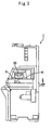
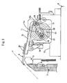
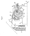
- a stitch presser control mechanism 9 for operating a presser bar 8 is provided and is composed of a rotation energizing mechanism 14 mounted on an output shaft 11a of a motor 11 of a driving device 10 and a swinging link mechanism 15 of the presser bar 8, as illustrated in Figs. 3 through 7 .
- the rotation energizing mechanism 14 is provided for rotating the output shaft 11a of the motor 11 to a side for retracting the presser bar 8 from the mouth portion 2 of the weft knitting machine 1 when electric power is not supplied to the motor 11, and a casing 18 composed of a housing 16 made of synthetic resin, in which space for containing a spring is formed inside thereof, and a thin metal lid 17 for covering an opening of the housing 16, in which a spiral spring 19 is contained, are provided.
- the spiral spring 19 is fixed to a fixing pin 20 formed on an operation arm 23, described later, which is mounted on the output shaft 11a of the motor 11 at an end 19a at the center of the spiral spring and the other end 19b at the periphery of the spiral spring is fixed to the housing 16 (a fixing member of a carriage side) with a fixing member 21.
- the above-described swinging mechanism 15 of the presser bar 8 is composed of a pair of front and back parallel link plates 24, 24, which are rotatably supported by fixing members (not shown) at the carriage 6 side at their lower ends, a presser bar supporting arm 25 supported by the upper ends of the parallel link plates 24, 24, an operation rod 26 that pushes and pulls a rotatable supporting portion 24a at an upper end of one of the parallel link plates 24, 24 (at the upper right part in Fig. 3 ) by means of a rotating force of the operation arm 23 attached to the output shaft 11a of the motor 11, and a position detecting mechanism 27, as illustrated in Figs. 3 through 7 .
- the shape of the presser bar 8 is approximately the same as the shape of the conventional presser bar 8 having a fabric pressing portion 8a in the weft knitting machine proposed previously by the inventor of the present invention, and is attached to an end portion of a side of the mouth portion 2 of the presser bar supporting arm 25 by a fixing member.
- a length of one of the parallel link plates 24, 24, which is joined to the operation rod 26, is larger than that of the other parallel link plate 24 and the fabric pressing portion 8a of the presser bar 8 thereby performs advancing and retracting swing in the manner of drawing an arc.
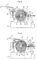
- the position detecting mechanism 27 is composed of a detecting piece 28 attached to an output shaft 11b of the motor 11 projecting to the opposite side of the motor 11 and two proximity sensors 29, 29 for detecting the detecting piece 28, as illustrated in Figs. 5 and 6 .
- One of the proximity sensors 29, 29 serves as a detector for detecting the approach of the presser bar 8 into the mouth portion 2 and the other proximity sensor 29 serves as a detector for detecting the withdrawal of the presser bar 8 from the mouth portion 2.
- the knitted fabric is produced while the carriage 6 is reciprocatingly sliding on the needle beds 3, 3.
- the presser bar 8 is changed to the other presser bar 8 that follows the direction of the reciprocating motion of the carriage 6 when the stitch presser is used for knitting the fabric. Therefore, one of presser bars 8 remains in the mouth portion 2, as illustrated in Fig. 3 .
- the spiral spring 19 is in a state of being wound up by a rotation of the output shaft 11a of the motor 11 resisting an elastic force thereof until the proximity sensor 29 of the position detecting mechanism 27 for detecting the approach of the presser bar 8 detects the detecting piece 28 attached to the output shaft 11b of the motor 11, as illustrated in Fig. 8 .
- the shape of the spring is not limited to a spiral and a coil spring having a circular cross section can of course be used.
- the stitch presser in the weft knitting machine of the present invention is provided with the rotation energizing mechanism for rotating the rotation shaft of the motor to a side for retracting the presser bar from the mouth portion of the weft knitting machine when the electric power supplied to the motor is stopped. Therefore, when, for example, a malfunction occurs in the weft knitting machine and the electric power to be supplied to the weft knitting machine is stopped, the drive of the motor that was driving the presser bar to advance into the mouth portion is stopped. Then, the rotation shaft of the motor is disengaged so that it rotates freely, and is rotated in such a direction that the presser bar can be retracted from the mouth portion by the rotation energizing mechanism.
- the carriage can be moved across the bracket without restriction so as to be detached from the weft knitting machine for an unexpected replacement of the knitting cam, or the like. Therefore, it is advantageous that the trouble and time required for moving the carriage to be detached from the weft knitting machine can be reduced.
Landscapes
- Engineering & Computer Science (AREA)
- Textile Engineering (AREA)
- Knitting Machines (AREA)
Claims (2)
- Maschenpresser für eine Schussstrickmaschine (1), der auf einem Schlitten (6) installiert werden soll, der sich in einer hin- und hergehenden Weise auf einem Nadelbett (3) verschiebt, und wobei der Maschenpresser eine Pressschiene und einen Motor aufweist und so ausgebildet ist, dass die Pressschiene (8) in einen Öffnungsabschnitt der Schussstrickmaschine (1) als Reaktion auf die Drehung einer Welle (11a) des Motors (11) transportiert wird, wobei die elektrische Energie, die dem Motor (11) zugeführt wird, die vorgegebene Pressschiene (8) in Verbindung mit einem richtungsabhängigen Schalten der hin- und hergehenden Bewegung des Schlittens (6) antreibt, wobei der Maschenpresser dadurch gekennzeichnet ist, dass er außerdem einen Drehungseinschaltmechanismus (14) für das Drehen der Rotationswelle (11a) des Motors nach einer Seite für das Zurückziehen der Pressschiene (8) aus dem Öffnungsabschnitt der Schussstrickmaschine (1) aufweist, wenn die elektrische Energie nicht dem Motor (11) für das Antreiben der Pressschiene (8) zugeführt wird, die in den Öffnungsabschnitt transportiert wird.
- Maschenpresser für eine Schussstrickmaschine nach Anspruch 1, bei dem der Drehungseinschaltmechanismus (14) aus einer Spiralfeder (19) oder einer Schraubenfeder gebildet wird, und bei dem ein Ende davon mit der Rotationswelle (11a) des Motors (11) oder einem Element verbunden ist, die/das sich als Reaktion auf die Drehung des Motors (11) bewegt, und bei dem das andere Ende davon mit einem Befestigungselement der Schlittenseite verbunden ist.
Applications Claiming Priority (3)
| Application Number | Priority Date | Filing Date | Title |
|---|---|---|---|
| JP2003028122 | 2003-02-05 | ||
| JP2003028122 | 2003-02-05 | ||
| PCT/JP2004/001017 WO2004070099A1 (ja) | 2003-02-05 | 2004-02-02 | 横編機におけるステッチプレッサー |
Publications (3)
| Publication Number | Publication Date |
|---|---|
| EP1595989A1 EP1595989A1 (de) | 2005-11-16 |
| EP1595989A4 EP1595989A4 (de) | 2006-09-06 |
| EP1595989B1 true EP1595989B1 (de) | 2011-03-30 |
Family
ID=32844191
Family Applications (1)
| Application Number | Title | Priority Date | Filing Date |
|---|---|---|---|
| EP04707312A Expired - Lifetime EP1595989B1 (de) | 2003-02-05 | 2004-02-02 | Maschenpresser für eine flachstrickmaschine |
Country Status (7)
| Country | Link |
|---|---|
| US (1) | US7059157B2 (de) |
| EP (1) | EP1595989B1 (de) |
| JP (1) | JP4176108B2 (de) |
| KR (1) | KR101025147B1 (de) |
| CN (1) | CN100424245C (de) |
| DE (1) | DE602004032012D1 (de) |
| WO (1) | WO2004070099A1 (de) |
Families Citing this family (5)
| Publication number | Priority date | Publication date | Assignee | Title |
|---|---|---|---|---|
| JP4015978B2 (ja) * | 2003-09-02 | 2007-11-28 | 株式会社島精機製作所 | 可動糸ガイド部材を備えた横編機 |
| JP5362233B2 (ja) * | 2008-02-15 | 2013-12-11 | 株式会社島精機製作所 | 生地押え装置 |
| CN101603238B (zh) * | 2009-06-22 | 2011-06-15 | 常熟市国光机械有限公司 | 电脑横机滑道式压圈装置 |
| US9404206B2 (en) * | 2013-02-28 | 2016-08-02 | Nike, Inc. | Feeder for knitting machine having pushing member |
| US12577710B2 (en) * | 2023-04-25 | 2026-03-17 | Nike, Inc. | Stitch-pressing component, knitting machine with stitch-pressing component, and methods of manufacturing, integrating, and using the same |
Family Cites Families (17)
| Publication number | Priority date | Publication date | Assignee | Title |
|---|---|---|---|---|
| US4501132A (en) * | 1977-11-03 | 1985-02-26 | Courtaulds Plc | Presser foot mechanism in a knitting machine |
| JPS57183451A (en) * | 1981-04-28 | 1982-11-11 | Shima Idea Center | Knitted cloth press apparatus in v bed traverse knitting machine |
| JPS588166A (ja) * | 1981-07-04 | 1983-01-18 | 株式会社三星製作所 | 横編機における編目押え用プレツサ−装置 |
| JPS5846156A (ja) * | 1981-09-16 | 1983-03-17 | 株式会社三星製作所 | 横編機における編目押え用プレツサ−装置 |
| JPS5964985U (ja) * | 1982-10-26 | 1984-04-28 | ブラザー工業株式会社 | 手編機の付属機構作動装置 |
| DE3362630D1 (en) * | 1982-12-09 | 1986-04-24 | Coats Ltd J & P | Loop hold-down device for use in conjunction with a knitting machine |
| JPS6119844A (ja) * | 1984-07-02 | 1986-01-28 | 株式会社 三星製作所 | 横編機における編目抑え用プレツサ−装置 |
| JPS6433249A (en) * | 1987-07-24 | 1989-02-03 | Mitsuboshi Seisakusho | Presser apparatus for pressing stitch in traverse knitting machine |
| IT212179Z2 (it) * | 1987-10-02 | 1989-07-04 | Emm Srl | Apparato per il supporto,il comando ed il controllo di organi pressamaglia-battimaglia in una macchina rettilinea per maglieria |
| JPH038841A (ja) * | 1989-06-02 | 1991-01-16 | Shima Seiki Seisakusho:Kk | Vベツド横編機における編地プレツサー |
| JPH03113058A (ja) * | 1989-09-28 | 1991-05-14 | Mitsuboshi Seisakusho:Kk | 横メリヤス編機における編目抑えプレッサー装置 |
| JP2602734B2 (ja) * | 1990-07-04 | 1997-04-23 | 株式会社島精機製作所 | 横編機におけるキャリッジのプレッサー制御装置 |
| JPH0672347B2 (ja) * | 1990-08-22 | 1994-09-14 | 株式会社島精機製作所 | 揺動シンカーとプレッサーバーを有する横編機 |
| CN2139585Y (zh) * | 1992-11-03 | 1993-08-04 | 赵刚 | 编织机压杆装置 |
| JP2602156B2 (ja) * | 1992-11-09 | 1997-04-23 | 株式会社島精機製作所 | 横編機の編地プレッサー |
| JP3140990B2 (ja) * | 1997-08-11 | 2001-03-05 | 株式会社島精機製作所 | 可動ループ形成プレートを備えた横編機 |
| JP3347079B2 (ja) * | 1998-12-16 | 2002-11-20 | 株式会社島精機製作所 | 横編機の端糸挿入装置 |
-
2004
- 2004-02-02 EP EP04707312A patent/EP1595989B1/de not_active Expired - Lifetime
- 2004-02-02 US US10/543,558 patent/US7059157B2/en not_active Expired - Fee Related
- 2004-02-02 DE DE602004032012T patent/DE602004032012D1/de not_active Expired - Lifetime
- 2004-02-02 KR KR1020057013478A patent/KR101025147B1/ko not_active Expired - Fee Related
- 2004-02-02 WO PCT/JP2004/001017 patent/WO2004070099A1/ja not_active Ceased
- 2004-02-02 CN CNB2004800033917A patent/CN100424245C/zh not_active Expired - Fee Related
- 2004-02-02 JP JP2005504819A patent/JP4176108B2/ja not_active Expired - Fee Related
Also Published As
| Publication number | Publication date |
|---|---|
| US20060090519A1 (en) | 2006-05-04 |
| WO2004070099A1 (ja) | 2004-08-19 |
| EP1595989A1 (de) | 2005-11-16 |
| KR20050094872A (ko) | 2005-09-28 |
| CN100424245C (zh) | 2008-10-08 |
| JP4176108B2 (ja) | 2008-11-05 |
| KR101025147B1 (ko) | 2011-03-31 |
| JPWO2004070099A1 (ja) | 2006-05-25 |
| DE602004032012D1 (de) | 2011-05-12 |
| EP1595989A4 (de) | 2006-09-06 |
| US7059157B2 (en) | 2006-06-13 |
| CN1745205A (zh) | 2006-03-08 |
Similar Documents
| Publication | Publication Date | Title |
|---|---|---|
| JP3899269B2 (ja) | 横編機の給糸装置 | |
| KR101040666B1 (ko) | 2본침 침절환 패턴 재봉기 | |
| JP2602156B2 (ja) | 横編機の編地プレッサー | |
| US7059157B2 (en) | Stitch presser in a weft knitting machine | |
| EP0472341B1 (de) | Flachstrickmaschine mit Schwingplatinen und Druckleisten | |
| JPH05192464A (ja) | ミシンの布押え駆動装置 | |
| JP3463210B2 (ja) | 横編機のカム用移動装置 | |
| JP5329811B2 (ja) | 横編機のキャリッジ搭載ユニット | |
| JPS6025535B2 (ja) | 編み機用給糸切換装置 | |
| EP2341172B1 (de) | Stickschlossvorrichtung | |
| EP2130962B1 (de) | Verfahren zur Herstellung von Textilartikeln mit Kettenwirkmaschinen und Maschine zur Durchführung eines solchen Verfahrens | |
| JPH038841A (ja) | Vベツド横編機における編地プレツサー | |
| KR101576837B1 (ko) | 가동싱커를 구비하는 횡편기 | |
| CN101063250B (zh) | 用于改进线型经编针织机的导纱器穿纱的装置 | |
| JPH05156553A (ja) | 横編機におけるカム出没切り換え装置 | |
| JPH03185161A (ja) | 手袋編等の横編機における度山制御装置 | |
| JP4860178B2 (ja) | ミシン | |
| CN220099325U (zh) | 横机的针织物压片装置 | |
| KR20060111454A (ko) | 이동체 연동상태 절환이 가능한 횡편기 | |
| CN111218767B (zh) | 一种无缝彩棉背心针织机的送纱装置 | |
| JP2003103081A (ja) | ミシン | |
| KR100297407B1 (ko) | 횡편기의 자동 편폭조절장치 | |
| JPH0610248A (ja) | 可動シンカーの揺動制御装置 | |
| KR200160322Y1 (ko) | 재봉틀용 스티칭실 이송기구 | |
| JPH01111047A (ja) | 編機 |
Legal Events
| Date | Code | Title | Description |
|---|---|---|---|
| PUAI | Public reference made under article 153(3) epc to a published international application that has entered the european phase |
Free format text: ORIGINAL CODE: 0009012 |
|
| 17P | Request for examination filed |
Effective date: 20050811 |
|
| AK | Designated contracting states |
Kind code of ref document: A1 Designated state(s): AT BE BG CH CY CZ DE DK EE ES FI FR GB GR HU IE IT LI LU MC NL PT RO SE SI SK TR |
|
| AX | Request for extension of the european patent |
Extension state: AL LT LV MK |
|
| DAX | Request for extension of the european patent (deleted) | ||
| RBV | Designated contracting states (corrected) |
Designated state(s): DE ES FR GB IT |
|
| A4 | Supplementary search report drawn up and despatched |
Effective date: 20060804 |
|
| GRAP | Despatch of communication of intention to grant a patent |
Free format text: ORIGINAL CODE: EPIDOSNIGR1 |
|
| RTI1 | Title (correction) |
Free format text: STITCH PRESSER FOR A WEFT KNITTING MACHINE |
|
| GRAS | Grant fee paid |
Free format text: ORIGINAL CODE: EPIDOSNIGR3 |
|
| GRAA | (expected) grant |
Free format text: ORIGINAL CODE: 0009210 |
|
| AK | Designated contracting states |
Kind code of ref document: B1 Designated state(s): DE ES FR GB IT |
|
| REG | Reference to a national code |
Ref country code: GB Ref legal event code: FG4D |
|
| REF | Corresponds to: |
Ref document number: 602004032012 Country of ref document: DE Date of ref document: 20110512 Kind code of ref document: P |
|
| REG | Reference to a national code |
Ref country code: DE Ref legal event code: R096 Ref document number: 602004032012 Country of ref document: DE Effective date: 20110512 |
|
| PG25 | Lapsed in a contracting state [announced via postgrant information from national office to epo] |
Ref country code: ES Free format text: LAPSE BECAUSE OF FAILURE TO SUBMIT A TRANSLATION OF THE DESCRIPTION OR TO PAY THE FEE WITHIN THE PRESCRIBED TIME-LIMIT Effective date: 20110711 |
|
| PLBE | No opposition filed within time limit |
Free format text: ORIGINAL CODE: 0009261 |
|
| STAA | Information on the status of an ep patent application or granted ep patent |
Free format text: STATUS: NO OPPOSITION FILED WITHIN TIME LIMIT |
|
| 26N | No opposition filed |
Effective date: 20120102 |
|
| REG | Reference to a national code |
Ref country code: DE Ref legal event code: R097 Ref document number: 602004032012 Country of ref document: DE Effective date: 20120102 |
|
| GBPC | Gb: european patent ceased through non-payment of renewal fee |
Effective date: 20120202 |
|
| REG | Reference to a national code |
Ref country code: FR Ref legal event code: ST Effective date: 20121031 |
|
| PG25 | Lapsed in a contracting state [announced via postgrant information from national office to epo] |
Ref country code: GB Free format text: LAPSE BECAUSE OF NON-PAYMENT OF DUE FEES Effective date: 20120202 Ref country code: FR Free format text: LAPSE BECAUSE OF NON-PAYMENT OF DUE FEES Effective date: 20120229 |
|
| PGFP | Annual fee paid to national office [announced via postgrant information from national office to epo] |
Ref country code: DE Payment date: 20140129 Year of fee payment: 11 |
|
| PGFP | Annual fee paid to national office [announced via postgrant information from national office to epo] |
Ref country code: IT Payment date: 20140220 Year of fee payment: 11 |
|
| REG | Reference to a national code |
Ref country code: DE Ref legal event code: R119 Ref document number: 602004032012 Country of ref document: DE |
|
| PG25 | Lapsed in a contracting state [announced via postgrant information from national office to epo] |
Ref country code: IT Free format text: LAPSE BECAUSE OF NON-PAYMENT OF DUE FEES Effective date: 20150202 |
|
| PG25 | Lapsed in a contracting state [announced via postgrant information from national office to epo] |
Ref country code: DE Free format text: LAPSE BECAUSE OF NON-PAYMENT OF DUE FEES Effective date: 20150901 |