EP1593136B1 - Elektrowerkzeug - Google Patents
Elektrowerkzeug Download PDFInfo
- Publication number
- EP1593136B1 EP1593136B1 EP03785826A EP03785826A EP1593136B1 EP 1593136 B1 EP1593136 B1 EP 1593136B1 EP 03785826 A EP03785826 A EP 03785826A EP 03785826 A EP03785826 A EP 03785826A EP 1593136 B1 EP1593136 B1 EP 1593136B1
- Authority
- EP
- European Patent Office
- Prior art keywords
- switching element
- electric tool
- switching elements
- tool
- molded body
- Prior art date
- Legal status (The legal status is an assumption and is not a legal conclusion. Google has not performed a legal analysis and makes no representation as to the accuracy of the status listed.)
- Expired - Lifetime
Links
- 230000001681 protective effect Effects 0.000 claims description 12
- 230000004913 activation Effects 0.000 claims description 7
- 238000013016 damping Methods 0.000 claims description 6
- 239000004065 semiconductor Substances 0.000 claims description 5
- 239000000428 dust Substances 0.000 claims description 4
- 239000000463 material Substances 0.000 claims description 4
- 238000011109 contamination Methods 0.000 claims description 3
- 239000002991 molded plastic Substances 0.000 claims 1
- 238000012216 screening Methods 0.000 claims 1
- 238000000926 separation method Methods 0.000 claims 1
- 230000011664 signaling Effects 0.000 abstract 1
- 238000011156 evaluation Methods 0.000 description 8
- 230000006870 function Effects 0.000 description 6
- 238000002955 isolation Methods 0.000 description 5
- 238000010586 diagram Methods 0.000 description 3
- RYGMFSIKBFXOCR-UHFFFAOYSA-N Copper Chemical compound [Cu] RYGMFSIKBFXOCR-UHFFFAOYSA-N 0.000 description 2
- 229910052802 copper Inorganic materials 0.000 description 2
- 239000010949 copper Substances 0.000 description 2
- 239000004020 conductor Substances 0.000 description 1
- 238000009713 electroplating Methods 0.000 description 1
- 238000002347 injection Methods 0.000 description 1
- 239000007924 injection Substances 0.000 description 1
- 238000009434 installation Methods 0.000 description 1
- 230000010354 integration Effects 0.000 description 1
- 229920001296 polysiloxane Polymers 0.000 description 1
- 230000009131 signaling function Effects 0.000 description 1
Images

Classifications
-
- H—ELECTRICITY
- H01—ELECTRIC ELEMENTS
- H01H—ELECTRIC SWITCHES; RELAYS; SELECTORS; EMERGENCY PROTECTIVE DEVICES
- H01H9/00—Details of switching devices, not covered by groups H01H1/00 - H01H7/00
- H01H9/02—Bases, casings, or covers
- H01H9/06—Casing of switch constituted by a handle serving a purpose other than the actuation of the switch, e.g. by the handle of a vacuum cleaner
-
- H—ELECTRICITY
- H01—ELECTRIC ELEMENTS
- H01H—ELECTRIC SWITCHES; RELAYS; SELECTORS; EMERGENCY PROTECTIVE DEVICES
- H01H9/00—Details of switching devices, not covered by groups H01H1/00 - H01H7/00
- H01H9/54—Circuit arrangements not adapted to a particular application of the switching device and for which no provision exists elsewhere
- H01H9/547—Combinations of mechanical switches and static switches, the latter being controlled by the former
Definitions
- the invention relates to a power tool with a motor for driving a tool and with at least one switching element.
- switches are required to turn the motor on and off, and possibly other control functions. It is customary here to use sufficiently robust switches which are designed for the rated operating voltage and are able to switch the sometimes quite high load currents in the range of up to more than 10 amperes. It understands These switches need to be designed to be robust enough not to fail in the professional sector with long operating times and numerous circuits.
- angle grinders which are designed as so-called "two-hand angle grinder", customary to form the rear end of the housing as a handle to which an on / off switch is provided, which is operated by a button.
- the angle grinder is then held with one hand during operation on a stem handle received on the side of the housing and with the other hand on the rear handle with the handle button being actuated. If the back handle is released, the power to the motor is interrupted and possibly initiated a braking of the angle grinder.
- switches could be provided at as many arbitrary positions as possible within the power tool and could be operated in the simplest possible and energy-saving manner.
- Such flexibility does not exist in conventional power tools, however, because the switches have a considerable size because of the sufficient dimensions and can be integrated only at certain locations in the housing.
- safety regulations are also to be observed, which is why, for example, an implementation of the supply line to a power switch by a motor housing is possible only with special protective measures that make such an arrangement considerably more expensive or even impossible.
- switching elements are provided for controlling the motor, which are located in a signal circuit and are coupled via a power switching element with a load circuit.
- a power tool with a motor which is equipped with a control element for driving the drive switching element, and which has a securing member, which cooperates with the switching member to ensure a two-handed operation on each of the two handles, an actuation of the switching member can only be done when embracing both handles.
- at least one of the two securing members is designed as an electrically effective line-shaped sensor which controls the drive via a control logic designed as a low voltage.
- the invention has for its object to provide a power tool having a further improved ergonomics.
- the operation of the power tool when gripped with one hand to be simplified.
- This invention is achieved in a power tool with a motor for driving a tool and at least one switching element which is located in a signal circuit and is coupled via at least one power switching element to a load circuit, that at least two Switching elements are provided which can be actuated via elastic touch surfaces, which are integrated in a housing, and that the touch surfaces are arranged in a handle portion of the housing, that the at least two switching elements are operable when grasping with one hand.
- the special arrangement of the elastic touch surfaces in the gripping region of a housing enables a plurality of switching elements to be actuated when gripped by one hand in order to be able to actuate certain switching elements when gripping the power tool with one hand,
- the switching elements are operated only in a signal circuit and thus have only reporting function, resulting from the reduced size significantly greater flexibility in the integration into the housing or in a handle. Since the switching elements only have a signaling function and thus are not subjected to the mains voltage, they can also be operated with low voltage, possibly galvanically decoupled from the load circuit. As already mentioned above, the protective measures for producing the necessary contact security of the power tool are thereby significantly simplified.
- a plurality of switching elements each lying in signal circuits and are coupled to a load circuit via at least one power switching element, are actuated by elastic touch surfaces, which are integrated into the housing of the power tool.
- the power switching element ensures electrical isolation of the load circuit from the signal circuit or the signal circuits.
- the power switching element may, for example, be designed as a relay or as a power semiconductor.
- a relay or as a power semiconductor.
- an opto-coupler with power semiconductor components is advantageous.
- the switching elements used preferably have the smallest possible size and are advantageously designed as a microswitch.
- a microswitch is understood to mean a switching element whose contact opening width between the different switching states is ⁇ 3 mm.
- Such a design as a microswitch opens due to the small size of the use of multiple switching elements at different points of the power tool to ensure a particularly ergonomic handling.
- two, three or even more switching elements may be provided at different locations in the grip area of the power tool, which can be actuated from the outside via elastic touch surfaces when the power tool is gripped.
- about one or more of the switching elements may be formed in an advantageous embodiment of the invention as a button.
- a power tool can be realized, which requires a permanent operation, for example by grasping a handle and immediately releases the power supply on release or possibly initiates braking.
- Such an embodiment is particularly advantageous in power tools with a relatively high hazard potential, such as angle grinders, portable circular saws or the like.
- a plurality of switching elements may be coupled to a circuit via which the motor is switched on when at least two switching elements are closed.
- the reliability is increased because it can be achieved that the motor is switched on only when a handle or a housing is taken at a specific point that allows the operation of the various switching elements. Furthermore, it can be provided that switching on the power tool is only possible when the power tool is gripped with two hands at different locations.
- the power tool has at least one actuating or attachment, which is associated with a switching element for state or position control.
- actuating or attachment numerous control options for an actuating or attachment are possible. For example, it can be ensured that a switching on of the motor is only possible if an actuating element, for example a clamping lever, is in a predetermined position. Furthermore, it can be ensured that, for example, starting of the motor is only possible if a specific attachment is in a predetermined installation position of the power tool.
- an actuating element for example a clamping lever
- the attachment for example in an embodiment of the power tool as an angle grinder or as a circular saw the attachment be designed as a protective cover and the switching element allow activation of the motor only when correctly mounted guard.
- the attachment is designed as a handle, which is associated with a switching element that allows activation of the motor only when the switching element via the handle.
- the power tool has a clamping lever for clamping the tool, which is movable between a clamping position and a release position, wherein the clamping lever is associated with a switching element for controlling the clamping position of the clamping lever.
- Such an embodiment is particularly advantageous in angle grinders having a clamping lever for tool-free voltage of the tool. So it can be ensured with simple means that the angle grinder can only be put into operation when the clamping lever is in the clamping position and thus the tool is securely clamped.
- a molded body held on the housing of the power tool is provided on which at least one receptacle is provided for fastening a switching element. It may be about a three-dimensionally shaped plastic part.
- the assembly can be simplified in particular when a plurality of switching elements to be integrated into the power tool.
- one or more electrical lines can be accommodated on the molded body, which can be connected to the switching element or the switching elements.
- suitable receptacles for fastening one or more switching elements can be provided on the molded body.
- the molded body can cooperate with the housing for shielding at least one switching element or electrical lines accommodated on the molded body from contamination by dust, moisture or the like.
- the molded body can be used in particular for shielding the switching elements used against dust and the like. As a result, the reliability is increased.
- the molded body can consist of a vibration-damping and / or acoustically damping material.
- means for electrically shielding at least one electrical line can be provided on the molded body.
- the entire wiring between the switching elements and the associated circuit, via which the load circuit is coupled, may be accommodated on the shaped body and formed approximately as a three-dimensionally shaped printed circuit board.
- the shielding can optionally be achieved by a one-sided full-surface copper layer.
- the switching elements according to the invention which are located in signal circuits and serve to control load circuits, are advantageously usable in portable power tools.
- stationary machine tools however, such applications are already known, whereby the invention is not suggested, however, since there are completely different requirements in stationary machines as in power tools.
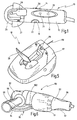
- FIG. 1 an inventive power tool is shown in the form of a single-handed angle grinder and designated overall by the numeral 10.
- the power tool 10 has an elongated housing 12, at the front end of a protective hood 27 is received.
- a clamping lever 28th For clamping a tool 29 in the form of a grinding wheel is a clamping lever 28th
- a total of three elastic touch surfaces are formed, namely a longitudinally oval shaped sensing surface 18 on the housing top, and two laterally arranged smaller touch surfaces 14, 16 on the left and right side wall of the housing 12.
- the touch surfaces 14, 16, 18 are made a readily deformable material, such as silicone, and are integrated into the housing 12, which ensures a dustproof design.
- Below the touch surfaces are associated switching elements 20, 22 in the small area Touch surfaces 14, 16 and 24, 26 in the region of the elongated touch surface 18th
- the arrangement of the switching elements 20 to 26 and the touch surfaces 14 to 18 is now made so that the housing can be easily grasped with one hand, wherein at least one of the switching elements 24, 26 in the region of the larger sensing surface 18 on the upper side of the housing and a switching element 20 or 22 in the region of the lateral touch surfaces 14 and 16 can be operated simultaneously when gripping with the left or right hand.
- the switching elements are designed as micro-switches, in this way a particularly ergonomic design and easy, energy-saving operation of the switching elements can be achieved.
- the arrangement may be such that the motor of the power tool 10 can only be activated if, when gripping the housing 12 with the right hand, one of the switching elements 24, 26 in the area of the large sensing surface 18 and the switching element 22 in the region of the left Tast Chemistry 16 is actuated. At the same time, activation of the motor is made possible when, when gripping with the left hand, one of the switching elements 24, 26 and the switching element 20 is actuated in the area of the right-hand sensing surface 14.
- Fig. 2 is a block diagram of such a power tool is generally designated by the numeral 30.
- a load circuit 40 is a motor 36, which for example via a power switching element 38 in the form of a thyristor a voltage source 32 is supplied with voltage. Possibly. can additionally be provided in the load circuit 40, an on / off switch 34, via which the device is put into operation.
- a number of switching elements 20, 22, 24, 26 is provided, which are each coupled via a signal circuit 42, 44, 46, 48 to a common evaluation circuit 50. From this evaluation circuit 50, the power switching element 38 is controlled via a control line 52. The evaluation circuit 50 can now enable activation of the power switching element 38 as a function of specific switching states of the switching elements 22 to 26. Depending on the desired output characteristic, different output signals may be provided depending on different input signal combinations on the signal circuits 42 to 48.
- An activation of the power switching element 38 can then be achieved if at least one of the switching elements 20 to 26 is switched on. Likewise, it is possible to achieve an engagement of the power switching element 38, if at least two or three of the individual switching elements 20 to 26 are turned on. Furthermore, a certain order in the switching of several switching elements may be assumed to turn on the power switching element 38. The chosen strategies can be adapted to the respective requirements of the respective power tool.
- the switching elements 20 to 26 in the signal circuits 42 to 48 need not be designed for switching the load current, but only a reporting function in the signal circuits 42 to have 48, the switching elements can be correspondingly weak dimensioned and designed as a microswitch. It can be used as switching elements with contact opening widths of ⁇ 3 mm. In contrast, the power switching element 38 is sufficiently dimensioned to switch the currents in the load circuit 40 can.
- the power switching element 38 may be of any design, provided that the necessary requirements for a reliable interruption of function are met and the necessary reliability in continuous operation after numerous circuits under high load is guaranteed.
- suitable power semiconductors such as thyristors, transistors, etc., in principle also relays come into question.
- the power switching element 38 as a relay. If the power switching element 38 is designed as a power semiconductor and controlled via an opto-coupler, the result is a particularly low-loss and reliable circuit with galvanic isolation.
- switching elements that only need to switch a signal voltage and not the full load current, they can be provided as a result of significantly smaller size and possibly the electrical isolation from the operating voltage at almost any point of the power tool 10. Also, a plurality of such switching elements may be provided at various locations, such as on or off enable the engine or to take over certain signal or control functions.
- a circuit 60 with a total of 5 switching elements 61, 62, 63, 64, 65 is shown.
- These switching elements 61 to 65 designed as microswitches can be actuated via elastic touch surfaces 66, 67, 68, 69, 70 and connected via signal circuits 71, 72, 73, 74, 75 to a suitable evaluation circuit 76.
- the power switching element 38 is then actuated again via the evaluation circuit 76. It is understood that depending on the application, in principle, several power switching elements can be provided. Moreover, it is possible to carry out the connection lines between the switching elements 61 to 65 and the associated connection elements such as the evaluation circuit 76 by means of a flexible printed circuit board.
- a generally designated by the numeral 78, three-dimensionally shaped molded body is shown.
- the molded body 78 has at predetermined locations receptacles 81, 82, 83, 84, 85 for receiving a respective switching element 61, 62, 63, 64, 65.
- electrical lines can be integrated in the molded body 78, which connect the switching elements 61 to 65, for example, with a common connector plug 79.
- a shield 86 can be integrated into the molded body 78, for example as a one-sided, continuous copper lining.
- the molded body 78 may consist of a vibration-damping and / or acoustically damping material and, for example, be formed as a plastic injection molded part. Electrical lines and possibly a shield can be suitably on the surface be applied as electrical conductors by means of conventional electroplating.
- the molded body can be adapted to the housing of the power tool in such a way that protection of the relevant switching elements and possibly lines against contamination by dust, moisture or the like is ensured.
- FIG. 5 shows a further use of a switching element 88 according to the invention in the region of a gear head 87 at the front end of the power tool 10.
- the power tool 10 in the form of the angle grinder has a clamping lever 28 for tool-free clamping of the tool 29.
- the clamping lever 28 is movable between a clamping position and between a release position, the latter being shown in FIG. Since for reasons of operational reliability commissioning should take place only when the clamping lever 28 is closed, the switching element 88 is provided, which is closed when moving the clamping lever 28 in the closed position. This signal is supplied via the connected line 89 of a connected evaluation circuit for further processing.
- a further embodiment of a power tool according to the invention is finally shown and designated by the numeral 90 in total.
- It is a so-called two-hand angle grinder.
- This has a housing 91 with a first handle 93 at the rear end of the housing, and a second handle 94 in the form of a handle handle, which is received either on the left side of the housing 91 in the region of the gear head 92 or on the opposite right side.
- the angle grinder is held with two hands, namely on the one hand on the rear handle 93 and the other on the handle handle 94.
- a commissioning of the motor is only possible if at least one switching element in the region of the handle 94 and a switching element in the region of the handle 93 is actuated.
- the power tool 90 has a protective cover 95, which is detachably attached to the housing 91.
- a further switching element 100 is provided, which is closed when the protective cover 95 is mounted correctly. Commissioning of the angle grinder is only possible with correctly installed protective cover 95.
Landscapes
- Finish Polishing, Edge Sharpening, And Grinding By Specific Grinding Devices (AREA)
- Push-Button Switches (AREA)
- Switch Cases, Indication, And Locking (AREA)
- Braking Systems And Boosters (AREA)
- Valve Device For Special Equipments (AREA)
- Cutting Tools, Boring Holders, And Turrets (AREA)
- Mechanisms For Operating Contacts (AREA)
- Portable Power Tools In General (AREA)
Description
- Die Erfindung betrifft ein Elektrowerkzeug mit einem Motor zum Antrieb eines Werkzeuges und mit mindestens einem Schaltelement.
- In Elektrowerkzeugen werden diverse Schalter zum Ein- und Ausschalten des Motors und ggf. zu weiteren Steuerfunktionen benötigt. Üblich ist es hierbei, ausreichend belastbare Schalter einzusetzen, die für die Nennbetriebsspannung ausgelegt sind und in der Lage sind, die teilweise recht hohen Lastströme im Bereich von bis zu mehr als 10 Ampere zu schalten. Es versteht sich, dass diese Schalter ausreichend robust ausgelegt sein müssen, um auch im professionellen Bereich bei langer Betriebsdauer und zahlreichen Schaltungen nicht auszufallen.
- In der Regel werden daher nur ein Ein-/Ausschalter oder höchstens zwei Ein-/Ausschalter verwendet, über die die Betätigung des Motors gesteuert wird. So ist es bspw. bei leistungsstarken Winkelschleifern, die als sogenannte "Zweihand-Winkelschleifer" ausgeführt sind, üblich, das rückwärtige Ende des Gehäuses als Griff auszubilden, an dem ein Ein-/Ausschalter vorgesehen ist, der über eine Taste zu betätigen ist. Der Winkelschleifer wird dann während des Betriebes an einem seitlich am Gehäuse aufgenommenen Stielhandgriff mit einer Hand und an dem rückwärtigen Handgriff mit der anderen Hand gehalten, wobei die Grifftaste betätigt wird. Wird der rückwärtige Handgriff losgelassen, so wird die Stromzufuhr zum Motor unterbrochen und ggf. eine Bremsung des Winkelschleifers eingeleitet.
- Zwecks einer verbesserten Ergonomie wäre es grundsätzlich erstrebenswert, wenn Schalter an möglichst beliebigen Positionen innerhalb des Elektrowerkzeuges vorgesehen werden könnten und auf möglichst einfache und kraftsparende Weise betätigt werden könnten. Eine derartige Flexibilität besteht bei herkömmlichen Elektrowerkzeugen jedoch nicht, da die Schalter wegen der ausreichenden Dimensionierung eine erhebliche Baugröße aufweisen und nur an bestimmten Stellen in das Gehäuse integriert werden können. Hierbei sind ferner Sicherheitsvorschriften zu beachten, weshalb bspw. eine Durchführung der Zuleitung zu einem Netzschalter durch ein Motorgehäuse nur bei besonderen Schutzmaßnahmen möglich ist, die eine derartige Anordnung erheblich verteuern oder gar unmöglich machen.
- Aus der
US-A-3 651 391 ist ein Elektrowerkzeug gemäß dem Oberbegriff von Anspruch 1 bekannt. Hierbei sind zur Steuerung des Motors Schaltelemente vorgesehen, die in einem Signalstromkreis liegen und über ein Leistungsschaltelement mit einem Laststromkreis gekoppelt sind. - Aus der
EP-A-0 628 762 ist ferner ein Elektrowerkzeug mit einem Motor bekannt, das mit einem für die Steuerung des Antriebes vorgesehenen Schaltglied ausgestattet ist, und das zur Sicherstellung einer Zweihand-Bedienung an jedem der zwei Handgriffe ein Sicherungsglied aufweist, das mit dem Schaltglied zusammenwirkt, dass eine Betätigung des Schaltgliedes nur beim Umfassen beider Handgriffe erfolgen kann. Hierbei ist zumindest eines der beiden Sicherungsglieder als elektrisch wirksamer linienförmiger Sensor ausgebildet, der über eine als Niederspannung ausgebildete Steuerlogik den Antrieb steuert. - vor diesem Hintergrund liegt der Erfindung die Aufgabe zugrunde, ein Elektrowerkzeug zu schaffen, das eine weiter verbesserte Ergonomie aufweist. Hierbei soll insbesondere die Betätigung des Elektrowerkzeuges bei Ergreifen mit einer Hand vereinfacht werden.
- Diese Erfindung wird bei einem Elektrowerkzeug mit einem Motor zum Antrieb eines Werkzeuges und mit mindestens einem Schaltelement, das in einem Signalstromkreis liegt und über mindestens ein Leistungsschaltelement mit einem Laststromkreis gekoppelt ist, dadurch gelöst, dass mindestens zwei Schaltelemente vorgesehen sind, die über elastische Tastflächen, die in ein Gehäuse integriert sind, betätigbar sind, und dass die Tastflächen derart in einem Griffbereich des Gehäuses angeordnet sind, dass die mindestens zwei Schaltelemente bei Umgreifen mit einer Hand betätigbar sind.
- Die Aufgabe der Erfindung wird auf diese Weise vollkommen gelöst.
- Erfindungsgemäß wird über die besondere Anordnung der elastischen Tastflächen im Griffbereich eines Gehäuses ermöglicht, dass mehrere Schaltelemente bei Umgreifen mit einer Hand betätigt werden können, um bei Ergreifen des Elektrowerkzeuges mit einer Hand bestimmte Schaltelemente betätigen zu können,
- Da die Schaltelemente lediglich in einem Signalstromkreis betrieben werden und somit lediglich Meldefunktion haben, ergibt sich durch die verringerte Baugröße eine deutlich größere Flexibilität bei der Integration in das Gehäuse oder etwa in einen Handgriff. Da die Schaltelemente lediglich eine Meldefunktion haben und somit nicht mit der Netzspannung beaufschlagt sind, können diese auch mit Niederspannung betrieben werden, ggf. galvanisch entkoppelt vom Laststromkreis. Wie vorstehend bereits erwähnt, werden hierdurch die Schutzmaßnahmen zur Herstellung der notwendigen Berührungssicherheit des Elektrowerkzeuges deutlich vereinfacht.
- Vorteilhafterweise werden mehrere Schaltelemente, die jeweils in Signalstromkreisen liegen und mit einem Laststromkreis über mindestens ein Leistungsschaltelement gekoppelt sind, über elastische Tastflächen betätigt werden, die in das Gehäuse des Elektrowerkzeuges integriert sind.
- Wie bereits erwähnt, ergeben sich weitere Vorteile, wenn das Leistungsschaltelement eine galvanische Trennung des Laststromkreises von dem Signalstromkreis oder den Signalstromkreisen gewährleistet.
- Das Leistungsschaltelement kann bspw. als Relais oder als Leistungshalbleiter ausgebildet sein. Um ein verschleißarmes Schalten zu gewährleisten und gleichzeitig eine galvanische Trennung zwischen Laststromkreis und Signalstromkreis zu erreichen, ist insbesondere eine Ausführung als Opto-Koppler mit Leistungshalbleiterbauelementen vorteilhaft.
- Die verwendeten Schaltelemente weisen vorzugsweise eine möglichst geringe Baugröße auf und sind vorteilhaft als Mikroschalter ausgebildet. Unter einem Mikroschalter wird in diesem Zusammenhang ein Schaltelement verstanden, dessen Kontaktöffnungsweite zwischen den verschiedenen schaltzuständen ≦ 3 mm ist.
- Eine derartige Ausführung als Mikroschalter eröffnet in Folge der geringen Baugröße den Einsatz von mehreren Schaltelementen an verschiedenen Stellen des Elektrowerkzeuges, um eine besonders ergonomische Handhabung zu gewährleisten. So können erfindungsgemäß zwei, drei oder auch mehr Schaltelemente an verschiedenen Stellen im Griffbereich des Elektrowerkzeuges vorgesehen sein, die bei Ergreifen des Elektrowerkzeuges von außen über elastische Tastflächen betätigbar sind.
- Hierbei können etwa ein oder mehrere der Schaltelemente in vorteilhafter Weiterbildung der Erfindung als Taster ausgebildet sein.
- Mit einer derartigen Ausführung kann ein Elektrowerkzeug realisiert werden, das eine dauerhafte Betätigung etwa durch Umgreifen eines Handgriffes erfordert und bei Loslassen sofort die Stromversorgung unterbricht oder ggf. eine Bremsung einleitet. Eine solche Ausgestaltung ist insbesondere bei Elektrowerkzeugen mit einem relativ hohen Gefährdungspotenzial, wie etwa Winkelschleifern, Handkreissägen oder dergleichen von Vorteil.
- Es können ferner mehrere Schaltelemente vorgesehen sein, über die der Motor einschaltbar ist, wenn mindestens ein Schaltelement geschlossen ist.
- Dies ermöglicht es, an verschiedenen Stellen des Elektrowerkzeuges Schaltelemente vorzusehen, die ein Einschalten des Motors ermöglichen, wenn wenigstens eines davon betätigt wird.
- In alternativer Ausführung der Erfindung können mehrere Schaltelemente mit einem Schaltkreis gekoppelt sein, über den der Motor einschaltbar ist, wenn mindestens zwei Schaltelemente geschlossen sind.
- Auf diese Weise wird die Betriebssicherheit erhöht, da erreicht werden kann, dass der Motor nur dann einschaltbar ist, wenn ein Handgriff oder ein Gehäuse an einer ganz bestimmten Stelle ergriffen wird, die die Betätigung der verschiedenen Schaltelemente ermöglicht. Des Weiteren kann vorgesehen sein, dass ein Einschalten des Elektrowerkzeuges nur dann ermöglicht ist, wenn das Elektrowerkzeug mit zwei Händen an unterschiedlichen Stellen ergriffen wird.
- Gemäß einer weiteren Ausführung der Erfindung weist das Elektrowerkzeug mindestens ein Betätigungs- oder Anbauteil auf, dem ein Schaltelement zur Zustands- oder Lagekontrolle zugeordnet ist.
- Auf diese Weise werden zahlreiche Kontrollmöglichkeiten für ein Betätigungs- oder Anbauteil ermöglicht. Bspw kann gewährleistet werden, dass ein Einschalten des Motors nur dann ermöglicht ist, wenn sich ein Betätigungselement, bspw. ein Spannhebel, in einer vorbestimmten Position befindet. Des Weiteren kann gewährleistet werden, dass etwa ein Anlaufen des Motors nur dann ermöglicht ist, wenn sich ein bestimmtes Anbauteil an einer vorbestimmten Einbaulage des Elektrowerkzeuges befindet.
- So kann gemäß einer weiteren Ausführung der Erfindung etwa bei einer Ausführung des Elektrowerkzeuges als Winkelschleifer oder als Handkreissäge das Anbauteil als Schutzhaube ausgebildet sein und das Schaltelement eine Aktivierung des Motors nur bei korrekt montierter Schutzhaube erlauben.
- Hierbei kann ferner etwa bei auswechselbaren Schutzhauben für Winkelschleifer gewährleistet werden, dass eine Inbetriebnahme nur dann ermöglicht ist, wenn die für den Winkelschleifer vorgesehene Schutzhaube eines bestimmten Typs montiert ist.
- Gemäß einer weiteren Ausführung der Erfindung ist das Anbauteil als Handgriff ausgebildet, dem ein Schaltelement zugeordnet ist, das eine Aktivierung des Motors nur bei Betätigung des Schaltelementes über den Handgriff erlaubt.
- Auf diese Weise kann die Betriebssicherheit insbesondere bei Zweihand-Winkelschleifern verbessert werden.
- Gemäß einer weiteren Ausführung der Erfindung weist das Elektrowerkzeug einen Spannhebel zum Spannen des Werkzeuges auf, der zwischen einer Spannposition und einer Löseposition bewegbar ist, wobei dem Spannhebel ein Schaltelement zur Kontrolle der Spannposition des Spannhebels zugeordnet ist.
- Eine derartige Ausführung ist insbesondere bei Winkelschleifern von Vorteil, die einen Spannhebel zur werkzeuglosen Spannung des Werkzeuges aufweisen. So kann mit einfachen Mitteln gewährleistet werden, dass sich der Winkelschleifer nur dann in Betrieb nehmen lässt, wenn sich der Spannhebel in der Spannposition befindet und somit das Werkzeug sicher gespannt ist.
- Gemäß einer weiteren Ausführung der Erfindung ist ein am Gehäuse des Elektrowerkzeuges gehaltener Formkörper vorgesehen, an dem mindestens eine Aufnahme zur Befestigung eines Schaltelementes vorgesehen ist. Es kann sich hierbei etwa um ein dreidimensional geformtes Kunststoffteil handeln.
- Auf diese Weise kann die Montage insbesondere dann vereinfacht werden, wenn eine Vielzahl von Schaltelementen in das Elektrowerkzeug integriert werden soll.
- Hierzu können an dem Formkörper eine oder mehrere elektrische Leitungen aufgenommen sein, die mit dem Schaltelement bzw. den Schaltelementen verbindbar sind. Des Weiteren können an dem Formkörper geeignete Aufnahmen zur Befestigung einer oder mehrerer Schaltelemente vorgesehen sein.
- Ferner kann der Formkörper mit dem Gehäuse zur Abschirmung von mindestens einem am Formkörper aufgenommenen Schaltelement oder elektrischen Leitungen gegenüber Kontamination durch Staub, Feuchtigkeit oder dergleichen zusammenwirken.
- Auf diese Weise kann der Formkörper insbesondere zur Abschirmung der verwendeten Schaltelemente gegenüber Staub und dergleichen- verwendet werden. Hierdurch wird die Betriebssicherheit erhöht.
- In zweckmäßiger Weiterbildung der Erfindung kann der Formkörper aus einem vibrationsdämpfenden und/oder akustisch dämpfenden Material bestehen.
- Dabei können ferner am Formkörper Mittel zur elektrischen Abschirmung mindestens einer elektrischen Leitung vorgesehen sein.
- Die gesamte Verdrahtung zwischen den Schaltelementen und der zugeordneten Schaltung, über die der Laststromkreis angekoppelt ist, kann auf dem Formkörper aufgenommen sein und etwa als dreidimensional geformte Leiterplatte ausgebildet sein. Hierbei kann die Abschirmung ggf. durch eine einseitig vollflächige Kupferschicht erreicht werden.
- Die erfindungsgemäßen Schaltelemente, die in Signalstromkreisen liegen und zur Steuerung von Laststromkreisen dienen, sind vorteilhaft bei tragbaren Elektrowerkzeugen verwendbar. Bei stationären Werkzeugmaschinen sind dagegen solche Anwendungen bereits bekannt, wodurch die Erfindung jedoch nicht nahegelegt ist, da bei stationären Maschinen gänzlich andere Anforderungen als bei Elektrowerkzeugen bestehen.
- Weitere Merkmale und Vorteile der Erfindung ergeben sich aus der nachfolgenden Beschreibung bevorzugter Ausführungsbeispiele unter Bezugnahme auf die Zeichnung. Es zeigen:
- Fig. 1
- eine vereinfachte perspektivische Ansicht einer ersten Ausführung eines erfindungsgemäßen Elektrowerkzeuges in Form eines Winkelschleifers;
- Fig. 2
- ein stark vereinfachtes Schaltbild eines erfindungsgemäßen Elektrowerkzeuges, aus dem die verwendeten Schaltelemente mit Signalstromkreisen und das Leistungsschaltelement im Laststromkreis ersichtlich sind;
- Fig. 3
- eine Prinzipdarstellung einer Schaltung mit insgesamt fünf Schaltelementen, die über elastische Tastflächen betätigbar sind und über eine gemeinsame Auswerteschaltung an einen Laststromkreis angekoppelt sind;
- Fig. 4
- eine perspektivische Ansicht eines dreidimensional geformten Formkörpers, an dem Aufnahmen für verschiedene Schaltelemente vorgesehen sind und in dem die elektrischen Verbindungsleitungen integriert sind;
- Fig. 5
- eine vergrößerte Darstellung des Elektrowerkzeuges gemäß Fig. 1 im Bereich des Getriebekopfes mit einem zugeordneten Schaltelement zur Lagekontrolle eines Spannhebels; und
- Fig. 6
- eine perspektivische Darstellung eines Elektrowerkzeuges in Form eines Zweihand-Winkelschleifers mit Schaltelementen im Bereich eines rückwärtigen Handgriffes am Ende des Gehäuses, im Bereich eines Stielhandgriffes und am Gehäuse zur Anbaukontrolle für eine zugeordnete Schutzhaube.
- In Fig. 1 ist ein erfindungsgemäßes Elektrowerkzeug in Form eines Einhand-Winkelschleifers dargestellt und insgesamt mit der Ziffer 10 bezeichnet.
- Das Elektrowerkzeug 10 weist ein längliches Gehäuse 12 auf, an dessen vorderem Ende eine Schutzhaube 27 aufgenommen ist. Zum Spannen eines Werkzeuges 29 in Form einer Schleifscheibe dient ein Spannhebel 28.
- Auf dem Gehäuse 12 sind insgesamt drei elastische Tastflächen ausgebildet, nämlich eine länglich oval ausgebildete Tastfläche 18 auf der Gehäuseoberseite, und zwei seitlich angeordnete kleinere Tastflächen 14, 16 an der linken und rechten Seitenwand des Gehäuses 12. Die Tastflächen 14, 16, 18 bestehen aus einem leicht deformierbaren Material, wie etwa Silicon, und sind in das Gehäuse 12 integriert, wodurch eine staubdichte Ausführung gewährleistet ist. Unterhalb der Tastflächen befinden sich zugeordnete Schaltelemente 20, 22 im Bereich der kleinen Tastflächen 14, 16 bzw. 24, 26 im Bereich der länglichen Tastfläche 18.
- Die Anordnung der Schaltelemente 20 bis 26 und der Tastflächen 14 bis 18 ist nunmehr so getroffen, dass das Gehäuse mit einer Hand leicht umgriffen werden kann, wobei gleichzeitig zumindest eines der Schaltelemente 24, 26 im Bereich der größeren Tastfläche 18 auf der Gehäuseoberseite und ein Schaltelement 20 oder 22 im Bereich der seitlichen Tastflächen 14 bzw. 16 bei Ergreifen mit der linken bzw. rechten Hand gleichzeitig betätigt werden können.
- Da die Schaltelemente, wie nachfolgend noch näher erläutert, als Mikroschalter ausgebildet sind, kann auf diese Weise eine besonders ergonomische Gestaltung und leichte, kraftsparende Betätigung der Schaltelemente erreicht werden. Dabei kann die Anordnung so getroffen sein, dass der Motor des Elektrowerkzeuges 10 nur dann aktiviert werden kann, wenn bei Ergreifen des Gehäuses 12 mit der rechten Hand eines der Schaltelemente 24, 26 im Bereich der großen Tastfläche 18 und das Schaltelement 22 im Bereich der linken Tastfläche 16 betätigt wird. Gleichzeitig wird eine Aktivierung des Motors ermöglicht, wenn bei Ergreifen mit der linken Hand eines der Schaltelemente 24, 26 und das Schaltelement 20 im Bereich der rechten Tastfläche 14 betätigt wird.
- In Fig. 2 ist ein Prinzipschaltbild eines derartigen Elektrowerkzeuges insgesamt mit der Ziffer 30 bezeichnet.
- In einem Laststromkreis 40 liegt ein Motor 36, der über ein Leistungsschaltelement 38 bspw. in Form eines Thyristors aus einer Spannungsquelle 32 mit Spannung versorgt wird. Ggf. kann zusätzlich im Laststromkreis 40 ein Ein-/Ausschalter 34 vorgesehen sein, über den das Gerät in Betrieb genommen wird.
- Ferner ist eine Reihe von Schaltelementen 20, 22, 24, 26 vorgesehen, die jeweils über einen Signalstromkreis 42, 44, 46, 48 an eine gemeinsame Auswerteschaltung 50 angekoppelt sind. Von dieser Auswerteschaltung 50 wird das Leistungsschaltelement 38 über eine Steuerleitung 52 angesteuert. Die Auswerteschaltung 50 kann nun eine Ansteuerung des Leistungsschaltelementes 38 in Abhängigkeit von bestimmten Schaltzuständen der Schaltelemente 22 bis 26 ermöglichen. Hierbei können je nach der gewünschten Ausgangscharakteristik verschiedene Ausgangssignale in Abhängigkeit von verschiedenen Eingangssignalkombinationen an den Signalstromkreisen 42 bis 48 vorgesehen sein.
- Bspw. kann eine Einschaltung des Leistungsschaltelementes 38 dann erreicht werden, wenn zumindest eines der Schaltelemente 20 bis 26 eingeschaltet ist. Gleichfalls ist es möglich, eine Einschaltung des Leistungsschaltelementes 38 zu erreichen, wenn mindestens zwei oder drei der einzelnen Schaltelemente 20 bis 26 eingeschaltet sind. Des Weiteren könnte eine bestimmte Reihenfolge bei der Einschaltung von mehreren Schaltelementen vorausgesetzt sein, um das Leistungsschaltelement 38 einzuschalten. Die gewählten Strategien können hierbei an die jeweiligen Anforderungen des betreffenden Elektrowerkzeuges angepasst werden.
- Da die Schaltelemente 20 bis 26 in den Signalstromkreisen 42 bis 48 nicht zur Schaltung des Laststromes ausgelegt sein müssen, sondern lediglich eine Meldefunktion in den Signalstromkreisen 42 bis 48 haben, können die Schaltelemente entsprechend schwach dimensioniert sein und als Mikroschalter ausgebildet sein. Es können so Schaltelemente mit Kontaktöffnungsweiten von ≦ 3 mm eingesetzt werden. Dagegen ist das Leistungsschaltelement 38 ausreichend dimensioniert, um die Ströme im Laststromkreis 40 schalten zu können.
- Es versteht sich, dass das Leistungsschaltelement 38 beliebiger Bauform sein kann, sofern die notwendigen Anforderungen an eine sichere Funktionsunterbrechung erfüllt werden und die notwendige Betriebssicherheit im Dauerbetrieb nach zahlreichen Schaltungen unter hoher Last gewährleistet ist. Neben geeigneten Leistungshalbleitern, wie Thyristoren, Transistoren, usw., kommen grundsätzlich auch Relais in Frage.
- Darüber hinaus ist es natürlich möglich, eine galvanische Trennung zwischen den Signalstromkreisen 42 bis 48 und dem Laststromkreis 40 zu gewährleisten, bspw. bei einer Ausführung des Leistungsschaltelementes 38 als Relais. Wird das Leistungsschaltelement 38 als Leistungshalbleiter ausgeführt und über einen Opto-Koppler angesteuert, so ergibt sich eine besonders verlustarme und betriebssichere Schaltung mit galvanischer Trennung.
- Durch die Verwendung von Schaltelementen, die lediglich eine Signalspannung schalten müssen und nicht den vollen Laststrom, können diese in Folge der deutlich geringeren Baugröße und ggf. der galvanischen Trennung gegenüber der Betriebsspannung an nahezu beliebigen Stellen des Elektrowerkzeuges 10 vorgesehen sein. Auch können mehrere derartige Schaltelemente an verschiedenen Stellen vorgesehen sein, um etwa ein Ein- oder Ausschalten des Motors zu ermöglichen oder aber um bestimmte Signal- oder Kontrollfunktionen zu übernehmen.
- In Fig. 3 ist eine Schaltung 60 mit insgesamt 5 Schaltelementen 61, 62, 63, 64, 65 dargestellt. Diese als Mikroschalter ausgeführten Schaltelemente 61 bis 65 sind über elastische Tastflächen 66, 67, 68, 69, 70 betätigbar und über Signalstromkreise 71, 72, 73, 74, 75 mit einer geeigneten Auswerteschaltung 76 verbunden. Über die Auswerteschaltung 76 wird dann wiederum das Leistungsschaltelement 38 angesteuert. Es versteht sich, dass je nach Anwendungsfall grundsätzlich auch mehrere Leistungsschaltelemente vorgesehen sein können. Darüber hinaus ist es möglich, die Verbindungsleitungen zwischen den Schaltelementen 61 bis 65 und den zugehörigen Anschlusselementen wie etwa der Auswerteschaltung 76 mittels einer flexiblen Leiterplatte auszuführen.
- In Fig. 4 ist ein insgesamt mit der Ziffer 78 bezeichneter, dreidimensional geformter Formkörper dargestellt. Der Formkörper 78 weist an vorbestimmten Stellen Aufnahmen 81, 82, 83, 84, 85 zur Aufnahme je eines Schaltelementes 61, 62, 63, 64, 65 auf. Ferner können in den Formkörper 78 elektrische Leitungen integriert sein, die die Schaltelemente 61 bis 65 bspw. mit einem gemeinsamen Anschlussstecker 79 verbinden. Des Weiteren kann in den Formkörper 78 eine Abschirmung 86 integriert sein, bspw. als eine einseitige, durchgehende Kupferkaschierung.
- Der Formkörper 78 kann aus einem vibrationsdämpfenden und/oder akustisch dämpfenden Material bestehen und bspw. als Kunststoffspritzgussteil ausgebildet sein. Elektrische Leitungen und ggf. eine Abschirmung können in geeigneter Weise auf der Oberfläche als elektrische Leiterbahnen mittels üblicher Galvanikverfahren aufgebracht sein.
- Der Formkörper kann gleichzeitig derart an das Gehäuse des Elektrowerkzeuges angepasst sein, dass hierdurch ein Schutz der betreffenden Schaltelemente und ggf. Leitungen gegenüber einer Kontamination durch Staub, Feuchtigkeit oder dergleichen gewährleistet ist.
- In Fig. 5 ist eine weitere Verwendung eines erfindungsgemäßen Schaltelementes 88 im Bereich eines Getriebekopfes 87 am vorderen Ende des Elektrowerkzeuges 10 dargestellt.
- Das Elektrowerkzeug 10 in Form des Winkelschleifers weist einen Spannhebel 28 zum werkzeuglosen Spannen des Werkzeuges 29 auf. Der Spannhebel 28 ist zwischen einer Spannstellung und zwischen einer Lösestellung-bewegbar, wobei letztere in Fig. 5 dargestellt ist. Da aus Gründen der Betriebssicherheit eine Inbetriebnahme nur bei geschlossenem Spannhebel 28 erfolgen soll, ist das Schaltelement 88 vorgesehen, das bei Bewegen des Spannhebels 28 in die Schließstellung geschlossen wird. Dieses Signal wird über die angeschlossene Leitung 89 einer angeschlossenen Auswerteschaltung zur weiteren Verarbeitung zugeführt.
- In Fig. 6 ist schließlich eine weitere Ausführung eines erfindungsgemäßen Elektrowerkzeuges dargestellt und insgesamt mit der Ziffer 90 bezeichnet.
- Es handelt sich um einen sogenannten Zweihand-Winkelschleifer. Dieser besitzt ein Gehäuse 91 mit einem ersten Handgriff 93 am rückwärtigen Ende des Gehäuses, sowie einen zweiten Handgriff 94 in Form eines Stielhandgriffes, der entweder an der linken Seite des Gehäuses 91 im Bereich des Getriebekopfes 92 oder an der gegenüberliegenden rechten Seite aufgenommen ist.
- Im Betrieb wird der Winkelschleifer mit zwei Händen gehalten, nämlich zum einen am rückwärtigen Handgriff 93 und zum anderen am Stielhandgriff 94. An beiden Handgriffen 93, 94 sind zugeordnete Tastflächen 96, 97 bzw. 98, 99 vorgesehen, über die nicht dargestellte Mikroschalter bei Ergreifen betätigt werden können. Ein Inbetriebsetzen des Motors ist nur dann möglich, wenn zumindest ein Schaltelement im Bereich des Handgriffes 94 und ein Schaltelement im Bereich des Handgriffes 93 betätigt wird.
- Darüber hinaus weist das Elektrowerkzeug 90 eine Schutzhaube 95 auf, die am Gehäuse 91 abnehmbar befestigt ist. Zur Kontrolle, ob eine Schutzhaube des korrekten Typs in der korrekten Einbaulage montiert ist, ist ein weiteres Schaltelement 100 vorgesehen, das bei korrekter Montage der vorgesehenen Schutzhaube 95 geschlossen ist. Eine Inbetriebnahme des Winkelschleifers ist nur bei korrekt montierter Schutzhaube 95 ermöglicht.
Claims (18)
- Elektrowerkzeug mit einem Motor (36) zum Antrieb eines Werkzeuges (29) und mit mindestens zwei Schaltelementen (20, 22, 24, 26, 61, 62, 63, 64, 65, 88, 100), die in einem Signalstromkreis (42, 44, 46, 48, 71, 72, 73, 74, 75) liegen und über mindestens ein Leistungsschaltelement (38) mit einem Laststromkreis (40) gekoppelt sind, wobei die mindestens zwei Schaltelemente (20, 22, 24, 26, 61, 62, 63, 64, 65, 88, 100) über Tastflächen (14, 16, 18, 66, 67, 68, 69, 70, 96, 97, 98, 99), die in ein Gehäuse (12, 87, 91) integriert sind, betätigbar sind, dadurch gekennzeichnet dass die Tastflächen elastisch sind und derart in einem Griffbereich des Gehäuses angeordnet sind, dass die mindestens zwei Schaltelemente bei Umgreifen mit einer Hand betätigbar sind.
- Elektrowerkzeug nach Anspruch 1, dadurch gekennzeichnet, dass die mindestens zwei Schaltelemente (20, 22, 24, 26, 61, 62, 63, 64, 65, 88, 100) jeweils in einem Signalstromkreis (42, 44, 46, 48, 71, 72, 73, 74, 75) liegen und über mindestens ein Leistungsschaltelement (38) mit einem Laststromkreis (40) gekoppelt sind, über den ein Motor (36) zum Antrieb eines Werkzeuges (29) steuerbar ist.
- Elektrowerkzeug nach Anspruch 1 oder 2, dadurch gekennzeichnet, dass das Leistungsschaltelement (38) eine galvanische Trennung des Laststromkreises (40) von jedem Signalstromkreis (42, 44, 46, 48, 71, 72, 73, 74, 75) gewährleistet.
- Elektrowerkzeug nach einem der vorhergehenden Ansprüche, dadurch gekennzeichnet, dass das Leistungsschaltelement (38) als Relais oder als Leistungshalbleiter, insbesondere mit Opto-Kopplung, ausgebildet ist.
- Elektrowerkzeug nach einem der vorhergehenden Ansprüche, dadurch gekennzeichnet, dass zumindest ein Schaltelement (20, 22, 24, 26, 61, 62, 63, 64, 65, 88, 100) als Mikroschalter ausgebildet ist.
- Elektrowerkzeug nach einem der vorhergehenden Ansprüche, dadurch gekennzeichnet, dass zumindest ein Schaltelement (20, 22, 24, 26, 61, 62, 63, 64, 65, 88, 100) als Taster ausgebildet ist.
- Elektrowerkzeug nach Anspruch 6, dadurch gekennzeichnet, dass mehrere Schaltelemente (20, 22, 24, 26, 61, 62, 63, 64, 65, 88, 100) mit einem Schaltkreis (50, 76) gekoppelt sind, über den der Motor (36) einschaltbar ist, wenn mindestens ein Schaltelement (20, 22, 24, 26, 61, 62, 63, 64, 65, 88, 100) geschlossen ist.
- Elektrowerkzeug nach Anspruch 6, dadurch gekennzeichnet, dass mehrere Schaltelemente (20, 22, 24, 26, 61, 62, 63, 64, 65, 88, 100) mit einem Schaltkreis (50, 76) gekoppelt sind, über den der Motor (36) einschaltbar ist, wenn mindestens zwei Schaltelemente (20, 22, 24, 26, 61, 62, 63, 64, 65, 88, 100) geschlossen sind.
- Elektrowerkzeug nach einem der vorhergehenden Ansprüche, dadurch gekennzeichnet, dass mindestens ein Betätigungs- oder Anbauteil (28, 94, 95) vorgesehen ist, dem ein Schaltelement (88, 100) zur Zustands- oder Lagekontrolle zugeordnet ist.
- Elektrowerkzeug nach Anspruch. 9, dadurch gekennzeichnet, dass das Elektrowerkzeug als Winkelschleifer oder als Handkreissäge ausgebildet ist, bei dem das Anbauteil als Schutzhaube (95) ausgebildet ist und das Schaltelement (100) eine Aktivierung des Motors (36) nur bei korrekt montierter Schutzhaube (95) erlaubt.
- Elektrowerkzeug nach Anspruch 9 oder 10, dadurch gekennzeichnet, dass das Anbauteil als Handgriff (93) ausgebildet ist, dem ein Schaltelement zugeordnet ist, das eine Aktivierung des Motors (36) nur bei Betätigung des Schaltelementes über den Handgriff (93) erlaubt.
- Elektrowerkzeug nach einem der vorhergehenden Ansprüche, dadurch gekennzeichnet, dass ein Spannhebel (28) zum Spannen des Werkzeuges (29) zwischen einer Spannposition und einer Löseposition bewegbar ist, und dass dem Spannhebel (28) ein Schaltelement (88) zur Kontrolle der Spannposition des Spannhebels (28) zugeordnet ist.
- Elektrowerkzeug nach einem der vorhergehenden Ansprüche, gekennzeichnet durch ein an einem Gehäuse (12, 91) gehaltenen Formkörper (78), an dem mindestens eine Aufnahme (81, 82, 83, 84, 85) zur Befestigung eines Schaltelementes (61, 62, 63, 64, 65) vorgesehen ist.
- Elektrowerkzeug nach einem der vorhergehenden Ansprüche, gekennzeichnet durch einen an einem Gehäuse (12, 91) gehaltenen Formkörper (78), an dem mindestens eine elektrische Leitung aufgenommen ist, die mit einem Schaltelement (61, 62, 63, 64, 65) verbindbar ist.
- Elektrowerkzeug nach Anspruch 13 oder 14, dadurch gekennzeichnet, dass der Formkörper (78) mit dem Gehäuse (12, 91) zur Abschirmung von mindestens einem am Formkörper (78) aufgenommenen Schaltelement (61, 62, 63, 64, 65) oder elektrischen Leitung gegenüber Kontamination durch Staub, Feuchtigkeit oder dergleichen zusammenwirkt.
- Elektrowerkzeug nach einem der Ansprüche 13 bis 15, dadurch gekennzeichnet, dass der Formkörper (78) aus einem vibrationsdämpfenden und/oder akustisch dämpfenden Material besteht.
- Elektrowerkzeug nach einem der Ansprüche 13 bis 16, dadurch gekennzeichnet, dass der Formkörper (78) als dreidimensional geformtes Kunststoffteil ausgebildet ist.
- Elektrowerkzeug nach einem der Ansprüche 13 bis 17, dadurch gekennzeichnet, dass der Formkörper (78) Mittel (86) zur elektrischen Abschirmung mindestens einer elektrischen Leitung aufweist.
Applications Claiming Priority (3)
| Application Number | Priority Date | Filing Date | Title |
|---|---|---|---|
| DE10306682 | 2003-02-13 | ||
| DE10306682A DE10306682A1 (de) | 2003-02-13 | 2003-02-13 | Elektrowerkzeug |
| PCT/EP2003/014277 WO2004073005A1 (de) | 2003-02-13 | 2003-12-16 | Elektrowerkzeug |
Publications (2)
| Publication Number | Publication Date |
|---|---|
| EP1593136A1 EP1593136A1 (de) | 2005-11-09 |
| EP1593136B1 true EP1593136B1 (de) | 2007-08-15 |
Family
ID=32747965
Family Applications (1)
| Application Number | Title | Priority Date | Filing Date |
|---|---|---|---|
| EP03785826A Expired - Lifetime EP1593136B1 (de) | 2003-02-13 | 2003-12-16 | Elektrowerkzeug |
Country Status (7)
| Country | Link |
|---|---|
| US (1) | US7507925B2 (de) |
| EP (1) | EP1593136B1 (de) |
| JP (1) | JP4975968B2 (de) |
| AT (1) | ATE370506T1 (de) |
| DE (2) | DE10306682A1 (de) |
| ES (1) | ES2291726T3 (de) |
| WO (1) | WO2004073005A1 (de) |
Cited By (2)
| Publication number | Priority date | Publication date | Assignee | Title |
|---|---|---|---|---|
| US11813729B2 (en) | 2018-05-14 | 2023-11-14 | Black & Decker Inc. | Power tool with partition assembly between transmission and motor |
| US11817757B2 (en) | 2018-05-14 | 2023-11-14 | Black & Decker Inc. | Power tool with partition assembly between transmission and motor |
Families Citing this family (15)
| Publication number | Priority date | Publication date | Assignee | Title |
|---|---|---|---|---|
| DE202006011224U1 (de) * | 2006-07-21 | 2007-11-22 | Wagner, Paul-Heinz | Drehschrauber |
| GB0711151D0 (en) * | 2007-06-11 | 2007-07-18 | Sra Dev Ltd | Switch for use with an ultrasonic surgical tool |
| DE102007042185A1 (de) | 2007-08-28 | 2009-03-05 | Metabowerke Gmbh | Elektrohandwerkzeuggerät |
| DE202008000921U1 (de) | 2008-01-23 | 2009-05-28 | Wagner, Paul-Heinz | Drehschrauber |
| US7832310B2 (en) * | 2008-07-18 | 2010-11-16 | Junkers John K | Torque power tool |
| DE102010030119A1 (de) * | 2010-06-15 | 2011-12-15 | Hilti Aktiengesellschaft | Eintreibvorrichtung |
| US8698430B2 (en) | 2010-09-17 | 2014-04-15 | Makita Corporation | Variable speed switch and electric power tool with the variable speed switch mounted thereto |
| US8872049B2 (en) | 2012-04-18 | 2014-10-28 | Milwaukee Electric Tool Corporation | Trigger lock-on lock-off mechanism |
| US20140166324A1 (en) * | 2012-12-13 | 2014-06-19 | Black & Decker Inc. | Power Tool User Interface |
| JP5766843B2 (ja) * | 2014-04-22 | 2015-08-19 | 株式会社マキタ | 変速スイッチ |
| US10519713B2 (en) * | 2015-07-01 | 2019-12-31 | Hunter Douglas Inc. | Static mitigation end cap for a covering for an architectural opening |
| EP3316270A1 (de) * | 2016-10-27 | 2018-05-02 | HILTI Aktiengesellschaft | Schaltervorrichtung für werkzeugmaschine |
| JP7212826B2 (ja) * | 2018-03-19 | 2023-01-26 | 京セラインダストリアルツールズ株式会社 | 電動工具 |
| US11670466B2 (en) | 2021-04-06 | 2023-06-06 | Robert Bosch Power Tool Corporation | Hand held rotary power tool |
| EP4342639A1 (de) * | 2022-09-23 | 2024-03-27 | C. & E. Fein GmbH | Lagervorrichtung für ein akkumulatormodul an einem handwerkzeug |
Family Cites Families (31)
| Publication number | Priority date | Publication date | Assignee | Title |
|---|---|---|---|---|
| US3651391A (en) * | 1969-09-26 | 1972-03-21 | Black & Decker Mfg Co | Electronic switch arrangements |
| JPS61726U (ja) * | 1984-06-08 | 1986-01-07 | 芝浦メカトロニクス株式会社 | 電動工具 |
| JPS61296619A (ja) * | 1985-06-25 | 1986-12-27 | 松下電工株式会社 | 電動工具のスイツチ装置 |
| JPH01216780A (ja) * | 1988-02-22 | 1989-08-30 | G M Van Reere Christian | 手持可能電動工具装置、電気スイツチ手段及びこれ等を含む作業キツト |
| FR2647588B1 (fr) | 1989-05-23 | 1996-07-19 | Moulinex Sa | Clavier interrupteur pour tableau de commande d'un appareil electrique |
| JP2517753Y2 (ja) * | 1989-11-02 | 1996-11-20 | 新ダイワ工業株式会社 | 電動工具用トリガスイッチ |
| JPH03113778U (de) * | 1990-03-09 | 1991-11-21 | ||
| JP2506697Y2 (ja) * | 1990-08-24 | 1996-08-14 | 日立工機株式会社 | 電動工具のスイッチ防じん用ゴムカバ― |
| DE4027135C2 (de) * | 1990-08-28 | 1995-09-07 | Gerhard Netz | Stichsäge mit Drehzahlregelung |
| DE4114854A1 (de) * | 1991-05-07 | 1992-11-12 | Marquardt Gmbh | Schalter, insbesondere akku-schalter fuer handbetaetigte elektrowerkzeuge |
| JPH0520872U (ja) * | 1991-08-30 | 1993-03-19 | 日本電気精器株式会社 | コードレスドライバ |
| DE9308698U1 (de) * | 1993-06-11 | 1994-10-27 | Dolmar GmbH, 22045 Hamburg | Handarbeitsgerät mit einem Antrieb |
| GB9320181D0 (en) * | 1993-09-30 | 1993-11-17 | Black & Decker Inc | Improvements in and relating to power tools |
| DE4336620C2 (de) * | 1993-10-27 | 1997-07-03 | Fein C & E | Elektrowerkzeug mit einer nur bei ausgeschaltetem Motor betätigbaren Spannvorrichtung |
| JPH07220563A (ja) * | 1994-02-03 | 1995-08-18 | Otax Kk | 電動工具用トリガースイッチ |
| DE4438045C2 (de) * | 1994-10-25 | 1996-11-07 | Atlas Copco Elektrowerkzeuge | Schalteinrichtung einer handgeführten Elektrowerkzeugmaschine |
| GB9423847D0 (en) * | 1994-11-25 | 1995-01-11 | Black & Decker Inc | Improved hand tool |
| US5675228A (en) * | 1995-12-18 | 1997-10-07 | General Electric Company | Methods and apparatus for controlling energization of a motor |
| JP3769873B2 (ja) * | 1996-06-03 | 2006-04-26 | オムロン株式会社 | トリガースイッチ |
| DE19715536C2 (de) * | 1997-04-14 | 2000-02-17 | Itt Mfg Enterprises Inc | Griffgehäuse mit eingebautem Schalter und Verfahren zu dessen Herstellung |
| WO1999050868A1 (en) * | 1998-03-27 | 1999-10-07 | Koninklijke Philips Electronics N.V. | Apparatus having a switch which is operable via a dome-shaped elastic cover |
| US6102632A (en) * | 1998-04-23 | 2000-08-15 | Black & Decker Inc. | Two speed right angle drill |
| US5990431A (en) * | 1998-05-18 | 1999-11-23 | Marquardt Switches, Inc. | Protective cover for rocker switch |
| DE19932578B4 (de) * | 1998-12-09 | 2005-04-14 | Helga Gabriel | Handführbare Vorrichtung zum Schleifen und/oder Trennen eines Werkstücks mit einem abdeckbaren Taster |
| DE19959920B4 (de) * | 1999-12-11 | 2004-03-25 | Metabowerke Gmbh | Elektrische Handwerkzeugmaschine, insbesondere Winkelschleifmaschine mit drehbarer Wartungsöffnung |
| GB0014806D0 (en) * | 2000-06-19 | 2000-08-09 | Black & Decker Inc | A power tool |
| JP3638009B2 (ja) * | 2000-08-23 | 2005-04-13 | ツインバード工業株式会社 | スイッチ取付構造 |
| US6608270B2 (en) * | 2000-10-20 | 2003-08-19 | Ethicon Endo-Surgery, Inc. | Flexible switch members for hand activation handpiece switches |
| DE10059712A1 (de) * | 2000-12-01 | 2002-06-20 | Bosch Gmbh Robert | Handwerkzeugmaschine |
| JP4019054B2 (ja) * | 2004-02-09 | 2007-12-05 | リョービ株式会社 | 電動工具 |
| US7322506B2 (en) * | 2004-04-02 | 2008-01-29 | Black & Decker Inc. | Electric driving tool with driver propelled by flywheel inertia |
-
2003
- 2003-02-13 DE DE10306682A patent/DE10306682A1/de not_active Withdrawn
- 2003-12-16 WO PCT/EP2003/014277 patent/WO2004073005A1/de not_active Ceased
- 2003-12-16 EP EP03785826A patent/EP1593136B1/de not_active Expired - Lifetime
- 2003-12-16 DE DE50307982T patent/DE50307982D1/de not_active Expired - Lifetime
- 2003-12-16 AT AT03785826T patent/ATE370506T1/de not_active IP Right Cessation
- 2003-12-16 ES ES03785826T patent/ES2291726T3/es not_active Expired - Lifetime
- 2003-12-16 JP JP2004568120A patent/JP4975968B2/ja not_active Expired - Fee Related
-
2005
- 2005-08-12 US US11/202,580 patent/US7507925B2/en not_active Expired - Fee Related
Non-Patent Citations (1)
| Title |
|---|
| None * |
Cited By (2)
| Publication number | Priority date | Publication date | Assignee | Title |
|---|---|---|---|---|
| US11813729B2 (en) | 2018-05-14 | 2023-11-14 | Black & Decker Inc. | Power tool with partition assembly between transmission and motor |
| US11817757B2 (en) | 2018-05-14 | 2023-11-14 | Black & Decker Inc. | Power tool with partition assembly between transmission and motor |
Also Published As
| Publication number | Publication date |
|---|---|
| US20060032650A1 (en) | 2006-02-16 |
| US7507925B2 (en) | 2009-03-24 |
| DE10306682A1 (de) | 2004-08-26 |
| DE50307982D1 (de) | 2007-09-27 |
| JP4975968B2 (ja) | 2012-07-11 |
| ATE370506T1 (de) | 2007-09-15 |
| WO2004073005A1 (de) | 2004-08-26 |
| EP1593136A1 (de) | 2005-11-09 |
| ES2291726T3 (es) | 2008-03-01 |
| JP2006513870A (ja) | 2006-04-27 |
Similar Documents
| Publication | Publication Date | Title |
|---|---|---|
| EP1593136B1 (de) | Elektrowerkzeug | |
| DE3216446C2 (de) | ||
| DE4418290A1 (de) | Betätigungsschalter für Elektrowerkzeuge | |
| DE202010008031U1 (de) | Verriegelungs-Schaltervorrichtung für ein Kraftwerkzeug | |
| EP1789235B1 (de) | Elektrowerkzeug mit doppeltem schalter | |
| DE9308698U1 (de) | Handarbeitsgerät mit einem Antrieb | |
| WO2022117311A1 (de) | Griff für eine werkzeugmaschine, werkzeugmaschine und verfahren zum einschalten, ausschalten und verriegeln derselben | |
| DE29902330U1 (de) | Bedien- und Bremsvorrichtung mit Zweihand-Steuersystem, insbesondere für Motorwerkzeuge | |
| DE19958297B4 (de) | Elektrowerkzeug mit verbesserter Schaltervorrichtung | |
| DE102020209908A1 (de) | Sicherheitsbedienvorrichtung und Werkzeugmaschinensystem mit der Sicherheitsbedienvorrichtung | |
| EP1284427B1 (de) | Lichtoptische Kontrolleinrichtung | |
| EP2066204B1 (de) | Sicherheitsmechanismus für eine küchenmaschine mit zwei kupplungsstellen | |
| DE19617882B4 (de) | Elektromotorische Heckenschere mit Zweihandbedienung | |
| DE2631994B2 (de) | Handwerkzeug mit einer von einem Motor angetriebenen Antriebsspindel | |
| DE102020213841B4 (de) | Signalschalter für elektrowerkzeuge | |
| EP2162979B1 (de) | Ansteuereinrichtung für einen elektromotor | |
| DE602004013191T2 (de) | Elektrowerkzeug mit doppelt steuerbarem schalter | |
| EP1472708A1 (de) | Elektrische schaltanordnung für ein elektrowerkzeug | |
| WO2008031711A1 (de) | Sicherheitsmechanismus für eine küchenmaschine mit rührschüssel und deckel | |
| EP1202648A2 (de) | Elektrisches haarbehandlungsgerät mit verdrehbarem bedienfeld | |
| DE3016615A1 (de) | Vorrichtung zum selbsttaetigen ausserbetriebsetzung einer handgefuehrten arbeitsmaschine | |
| EP0085730B1 (de) | Zweipoliger Druckschalter mit elektronischer Steuer- und Regeleinrichtung zum Einbau in von Hand benutzte Elektrogeräte | |
| EP1595661A1 (de) | Griff mit Sicherheitsvorrichtung für motorangetriebenes Handwerkzeug | |
| EP0686987B1 (de) | Vorrichtung zum reversierenden Umschalten eines Antriebsmotors | |
| DE102025121440A1 (de) | Handgeführtes Elektrogerät |
Legal Events
| Date | Code | Title | Description |
|---|---|---|---|
| PUAI | Public reference made under article 153(3) epc to a published international application that has entered the european phase |
Free format text: ORIGINAL CODE: 0009012 |
|
| 17P | Request for examination filed |
Effective date: 20050712 |
|
| AK | Designated contracting states |
Kind code of ref document: A1 Designated state(s): AT BE BG CH CY CZ DE DK EE ES FI FR GB GR HU IE IT LI LU MC NL PT RO SE SI SK TR |
|
| RAP3 | Party data changed (applicant data changed or rights of an application transferred) |
Owner name: C. & E. FEIN GMBH |
|
| RAP1 | Party data changed (applicant data changed or rights of an application transferred) |
Owner name: C. & E. FEIN GMBH |
|
| GRAP | Despatch of communication of intention to grant a patent |
Free format text: ORIGINAL CODE: EPIDOSNIGR1 |
|
| GRAS | Grant fee paid |
Free format text: ORIGINAL CODE: EPIDOSNIGR3 |
|
| GRAA | (expected) grant |
Free format text: ORIGINAL CODE: 0009210 |
|
| AK | Designated contracting states |
Kind code of ref document: B1 Designated state(s): AT BE BG CH CY CZ DE DK EE ES FI FR GB GR HU IE IT LI LU MC NL PT RO SE SI SK TR |
|
| REG | Reference to a national code |
Ref country code: GB Ref legal event code: FG4D Free format text: NOT ENGLISH |
|
| REG | Reference to a national code |
Ref country code: CH Ref legal event code: NV Representative=s name: TROESCH SCHEIDEGGER WERNER AG Ref country code: CH Ref legal event code: EP |
|
| GBT | Gb: translation of ep patent filed (gb section 77(6)(a)/1977) |
Effective date: 20070815 |
|
| REG | Reference to a national code |
Ref country code: IE Ref legal event code: FG4D Free format text: LANGUAGE OF EP DOCUMENT: GERMAN |
|
| REF | Corresponds to: |
Ref document number: 50307982 Country of ref document: DE Date of ref document: 20070927 Kind code of ref document: P |
|
| REG | Reference to a national code |
Ref country code: SE Ref legal event code: TRGR |
|
| ET | Fr: translation filed | ||
| PG25 | Lapsed in a contracting state [announced via postgrant information from national office to epo] |
Ref country code: FI Free format text: LAPSE BECAUSE OF FAILURE TO SUBMIT A TRANSLATION OF THE DESCRIPTION OR TO PAY THE FEE WITHIN THE PRESCRIBED TIME-LIMIT Effective date: 20070815 Ref country code: BG Free format text: LAPSE BECAUSE OF FAILURE TO SUBMIT A TRANSLATION OF THE DESCRIPTION OR TO PAY THE FEE WITHIN THE PRESCRIBED TIME-LIMIT Effective date: 20071115 |
|
| REG | Reference to a national code |
Ref country code: ES Ref legal event code: FG2A Ref document number: 2291726 Country of ref document: ES Kind code of ref document: T3 |
|
| REG | Reference to a national code |
Ref country code: IE Ref legal event code: FD4D |
|
| PG25 | Lapsed in a contracting state [announced via postgrant information from national office to epo] |
Ref country code: DK Free format text: LAPSE BECAUSE OF FAILURE TO SUBMIT A TRANSLATION OF THE DESCRIPTION OR TO PAY THE FEE WITHIN THE PRESCRIBED TIME-LIMIT Effective date: 20070815 Ref country code: GR Free format text: LAPSE BECAUSE OF FAILURE TO SUBMIT A TRANSLATION OF THE DESCRIPTION OR TO PAY THE FEE WITHIN THE PRESCRIBED TIME-LIMIT Effective date: 20071116 |
|
| PG25 | Lapsed in a contracting state [announced via postgrant information from national office to epo] |
Ref country code: CZ Free format text: LAPSE BECAUSE OF FAILURE TO SUBMIT A TRANSLATION OF THE DESCRIPTION OR TO PAY THE FEE WITHIN THE PRESCRIBED TIME-LIMIT Effective date: 20070815 Ref country code: IE Free format text: LAPSE BECAUSE OF FAILURE TO SUBMIT A TRANSLATION OF THE DESCRIPTION OR TO PAY THE FEE WITHIN THE PRESCRIBED TIME-LIMIT Effective date: 20070815 Ref country code: PT Free format text: LAPSE BECAUSE OF FAILURE TO SUBMIT A TRANSLATION OF THE DESCRIPTION OR TO PAY THE FEE WITHIN THE PRESCRIBED TIME-LIMIT Effective date: 20080115 Ref country code: SK Free format text: LAPSE BECAUSE OF FAILURE TO SUBMIT A TRANSLATION OF THE DESCRIPTION OR TO PAY THE FEE WITHIN THE PRESCRIBED TIME-LIMIT Effective date: 20070815 |
|
| PLBE | No opposition filed within time limit |
Free format text: ORIGINAL CODE: 0009261 |
|
| STAA | Information on the status of an ep patent application or granted ep patent |
Free format text: STATUS: NO OPPOSITION FILED WITHIN TIME LIMIT |
|
| BERE | Be: lapsed |
Owner name: C. & E. FEIN G.M.B.H. Effective date: 20071231 |
|
| PG25 | Lapsed in a contracting state [announced via postgrant information from national office to epo] |
Ref country code: RO Free format text: LAPSE BECAUSE OF FAILURE TO SUBMIT A TRANSLATION OF THE DESCRIPTION OR TO PAY THE FEE WITHIN THE PRESCRIBED TIME-LIMIT Effective date: 20070815 |
|
| 26N | No opposition filed |
Effective date: 20080516 |
|
| PG25 | Lapsed in a contracting state [announced via postgrant information from national office to epo] |
Ref country code: MC Free format text: LAPSE BECAUSE OF NON-PAYMENT OF DUE FEES Effective date: 20071231 |
|
| PG25 | Lapsed in a contracting state [announced via postgrant information from national office to epo] |
Ref country code: BE Free format text: LAPSE BECAUSE OF NON-PAYMENT OF DUE FEES Effective date: 20071231 |
|
| PG25 | Lapsed in a contracting state [announced via postgrant information from national office to epo] |
Ref country code: EE Free format text: LAPSE BECAUSE OF FAILURE TO SUBMIT A TRANSLATION OF THE DESCRIPTION OR TO PAY THE FEE WITHIN THE PRESCRIBED TIME-LIMIT Effective date: 20070815 |
|
| PG25 | Lapsed in a contracting state [announced via postgrant information from national office to epo] |
Ref country code: AT Free format text: LAPSE BECAUSE OF NON-PAYMENT OF DUE FEES Effective date: 20071216 |
|
| PG25 | Lapsed in a contracting state [announced via postgrant information from national office to epo] |
Ref country code: SI Free format text: LAPSE BECAUSE OF FAILURE TO SUBMIT A TRANSLATION OF THE DESCRIPTION OR TO PAY THE FEE WITHIN THE PRESCRIBED TIME-LIMIT Effective date: 20070815 |
|
| PG25 | Lapsed in a contracting state [announced via postgrant information from national office to epo] |
Ref country code: CY Free format text: LAPSE BECAUSE OF FAILURE TO SUBMIT A TRANSLATION OF THE DESCRIPTION OR TO PAY THE FEE WITHIN THE PRESCRIBED TIME-LIMIT Effective date: 20070815 |
|
| PG25 | Lapsed in a contracting state [announced via postgrant information from national office to epo] |
Ref country code: LU Free format text: LAPSE BECAUSE OF NON-PAYMENT OF DUE FEES Effective date: 20071216 |
|
| PG25 | Lapsed in a contracting state [announced via postgrant information from national office to epo] |
Ref country code: TR Free format text: LAPSE BECAUSE OF FAILURE TO SUBMIT A TRANSLATION OF THE DESCRIPTION OR TO PAY THE FEE WITHIN THE PRESCRIBED TIME-LIMIT Effective date: 20070815 Ref country code: HU Free format text: LAPSE BECAUSE OF FAILURE TO SUBMIT A TRANSLATION OF THE DESCRIPTION OR TO PAY THE FEE WITHIN THE PRESCRIBED TIME-LIMIT Effective date: 20080216 |
|
| PGFP | Annual fee paid to national office [announced via postgrant information from national office to epo] |
Ref country code: CH Payment date: 20141212 Year of fee payment: 12 Ref country code: SE Payment date: 20141211 Year of fee payment: 12 Ref country code: GB Payment date: 20141210 Year of fee payment: 12 Ref country code: ES Payment date: 20141111 Year of fee payment: 12 |
|
| PGFP | Annual fee paid to national office [announced via postgrant information from national office to epo] |
Ref country code: NL Payment date: 20141210 Year of fee payment: 12 Ref country code: FR Payment date: 20141208 Year of fee payment: 12 |
|
| PGFP | Annual fee paid to national office [announced via postgrant information from national office to epo] |
Ref country code: IT Payment date: 20141203 Year of fee payment: 12 |
|
| REG | Reference to a national code |
Ref country code: CH Ref legal event code: PL |
|
| REG | Reference to a national code |
Ref country code: SE Ref legal event code: EUG |
|
| GBPC | Gb: european patent ceased through non-payment of renewal fee |
Effective date: 20151216 |
|
| PG25 | Lapsed in a contracting state [announced via postgrant information from national office to epo] |
Ref country code: SE Free format text: LAPSE BECAUSE OF NON-PAYMENT OF DUE FEES Effective date: 20151217 |
|
| REG | Reference to a national code |
Ref country code: NL Ref legal event code: MM Effective date: 20160101 |
|
| REG | Reference to a national code |
Ref country code: FR Ref legal event code: ST Effective date: 20160831 |
|
| PG25 | Lapsed in a contracting state [announced via postgrant information from national office to epo] |
Ref country code: LI Free format text: LAPSE BECAUSE OF NON-PAYMENT OF DUE FEES Effective date: 20151231 Ref country code: NL Free format text: LAPSE BECAUSE OF NON-PAYMENT OF DUE FEES Effective date: 20160101 Ref country code: CH Free format text: LAPSE BECAUSE OF NON-PAYMENT OF DUE FEES Effective date: 20151231 Ref country code: GB Free format text: LAPSE BECAUSE OF NON-PAYMENT OF DUE FEES Effective date: 20151216 |
|
| PG25 | Lapsed in a contracting state [announced via postgrant information from national office to epo] |
Ref country code: FR Free format text: LAPSE BECAUSE OF NON-PAYMENT OF DUE FEES Effective date: 20151231 |
|
| PG25 | Lapsed in a contracting state [announced via postgrant information from national office to epo] |
Ref country code: IT Free format text: LAPSE BECAUSE OF NON-PAYMENT OF DUE FEES Effective date: 20151216 |
|
| REG | Reference to a national code |
Ref country code: ES Ref legal event code: FD2A Effective date: 20170126 |
|
| PG25 | Lapsed in a contracting state [announced via postgrant information from national office to epo] |
Ref country code: ES Free format text: LAPSE BECAUSE OF NON-PAYMENT OF DUE FEES Effective date: 20151217 |
|
| PGFP | Annual fee paid to national office [announced via postgrant information from national office to epo] |
Ref country code: DE Payment date: 20181204 Year of fee payment: 16 |
|
| REG | Reference to a national code |
Ref country code: DE Ref legal event code: R119 Ref document number: 50307982 Country of ref document: DE |
|
| PG25 | Lapsed in a contracting state [announced via postgrant information from national office to epo] |
Ref country code: DE Free format text: LAPSE BECAUSE OF NON-PAYMENT OF DUE FEES Effective date: 20200701 |