EP1592573B1 - Montagekonstruktion für elektrische fahrzeugeinrichtungen - Google Patents
Montagekonstruktion für elektrische fahrzeugeinrichtungen Download PDFInfo
- Publication number
- EP1592573B1 EP1592573B1 EP04710088A EP04710088A EP1592573B1 EP 1592573 B1 EP1592573 B1 EP 1592573B1 EP 04710088 A EP04710088 A EP 04710088A EP 04710088 A EP04710088 A EP 04710088A EP 1592573 B1 EP1592573 B1 EP 1592573B1
- Authority
- EP
- European Patent Office
- Prior art keywords
- seat
- vehicle
- floor panel
- battery
- fuel cell
- Prior art date
- Legal status (The legal status is an assumption and is not a legal conclusion. Google has not performed a legal analysis and makes no representation as to the accuracy of the status listed.)
- Expired - Lifetime
Links
- 239000000446 fuel Substances 0.000 claims abstract description 30
- 238000010276 construction Methods 0.000 description 4
- 239000002828 fuel tank Substances 0.000 description 4
- 230000007246 mechanism Effects 0.000 description 4
- 238000001816 cooling Methods 0.000 description 3
- HBBGRARXTFLTSG-UHFFFAOYSA-N Lithium ion Chemical compound [Li+] HBBGRARXTFLTSG-UHFFFAOYSA-N 0.000 description 2
- 238000011161 development Methods 0.000 description 2
- 230000018109 developmental process Effects 0.000 description 2
- 239000001257 hydrogen Substances 0.000 description 2
- 229910052739 hydrogen Inorganic materials 0.000 description 2
- 229910001416 lithium ion Inorganic materials 0.000 description 2
- 239000002253 acid Substances 0.000 description 1
- 230000002411 adverse Effects 0.000 description 1
- 238000002485 combustion reaction Methods 0.000 description 1
- 230000001419 dependent effect Effects 0.000 description 1
- 239000007789 gas Substances 0.000 description 1
- 238000009434 installation Methods 0.000 description 1
- 238000012986 modification Methods 0.000 description 1
- 230000004048 modification Effects 0.000 description 1
- 230000035515 penetration Effects 0.000 description 1
- 238000005057 refrigeration Methods 0.000 description 1
- 238000009423 ventilation Methods 0.000 description 1
- XLYOFNOQVPJJNP-UHFFFAOYSA-N water Substances O XLYOFNOQVPJJNP-UHFFFAOYSA-N 0.000 description 1
Images


Classifications
-
- B—PERFORMING OPERATIONS; TRANSPORTING
- B60—VEHICLES IN GENERAL
- B60K—ARRANGEMENT OR MOUNTING OF PROPULSION UNITS OR OF TRANSMISSIONS IN VEHICLES; ARRANGEMENT OR MOUNTING OF PLURAL DIVERSE PRIME-MOVERS IN VEHICLES; AUXILIARY DRIVES FOR VEHICLES; INSTRUMENTATION OR DASHBOARDS FOR VEHICLES; ARRANGEMENTS IN CONNECTION WITH COOLING, AIR INTAKE, GAS EXHAUST OR FUEL SUPPLY OF PROPULSION UNITS IN VEHICLES
- B60K1/00—Arrangement or mounting of electrical propulsion units
- B60K1/04—Arrangement or mounting of electrical propulsion units of the electric storage means for propulsion
-
- B—PERFORMING OPERATIONS; TRANSPORTING
- B60—VEHICLES IN GENERAL
- B60L—PROPULSION OF ELECTRICALLY-PROPELLED VEHICLES; SUPPLYING ELECTRIC POWER FOR AUXILIARY EQUIPMENT OF ELECTRICALLY-PROPELLED VEHICLES; ELECTRODYNAMIC BRAKE SYSTEMS FOR VEHICLES IN GENERAL; MAGNETIC SUSPENSION OR LEVITATION FOR VEHICLES; MONITORING OPERATING VARIABLES OF ELECTRICALLY-PROPELLED VEHICLES; ELECTRIC SAFETY DEVICES FOR ELECTRICALLY-PROPELLED VEHICLES
- B60L50/00—Electric propulsion with power supplied within the vehicle
- B60L50/50—Electric propulsion with power supplied within the vehicle using propulsion power supplied by batteries or fuel cells
- B60L50/60—Electric propulsion with power supplied within the vehicle using propulsion power supplied by batteries or fuel cells using power supplied by batteries
- B60L50/64—Constructional details of batteries specially adapted for electric vehicles
-
- B—PERFORMING OPERATIONS; TRANSPORTING
- B60—VEHICLES IN GENERAL
- B60L—PROPULSION OF ELECTRICALLY-PROPELLED VEHICLES; SUPPLYING ELECTRIC POWER FOR AUXILIARY EQUIPMENT OF ELECTRICALLY-PROPELLED VEHICLES; ELECTRODYNAMIC BRAKE SYSTEMS FOR VEHICLES IN GENERAL; MAGNETIC SUSPENSION OR LEVITATION FOR VEHICLES; MONITORING OPERATING VARIABLES OF ELECTRICALLY-PROPELLED VEHICLES; ELECTRIC SAFETY DEVICES FOR ELECTRICALLY-PROPELLED VEHICLES
- B60L50/00—Electric propulsion with power supplied within the vehicle
- B60L50/50—Electric propulsion with power supplied within the vehicle using propulsion power supplied by batteries or fuel cells
- B60L50/60—Electric propulsion with power supplied within the vehicle using propulsion power supplied by batteries or fuel cells using power supplied by batteries
- B60L50/66—Arrangements of batteries
-
- B—PERFORMING OPERATIONS; TRANSPORTING
- B60—VEHICLES IN GENERAL
- B60L—PROPULSION OF ELECTRICALLY-PROPELLED VEHICLES; SUPPLYING ELECTRIC POWER FOR AUXILIARY EQUIPMENT OF ELECTRICALLY-PROPELLED VEHICLES; ELECTRODYNAMIC BRAKE SYSTEMS FOR VEHICLES IN GENERAL; MAGNETIC SUSPENSION OR LEVITATION FOR VEHICLES; MONITORING OPERATING VARIABLES OF ELECTRICALLY-PROPELLED VEHICLES; ELECTRIC SAFETY DEVICES FOR ELECTRICALLY-PROPELLED VEHICLES
- B60L50/00—Electric propulsion with power supplied within the vehicle
- B60L50/50—Electric propulsion with power supplied within the vehicle using propulsion power supplied by batteries or fuel cells
- B60L50/70—Electric propulsion with power supplied within the vehicle using propulsion power supplied by batteries or fuel cells using power supplied by fuel cells
- B60L50/71—Arrangement of fuel cells within vehicles specially adapted for electric vehicles
-
- B—PERFORMING OPERATIONS; TRANSPORTING
- B60—VEHICLES IN GENERAL
- B60L—PROPULSION OF ELECTRICALLY-PROPELLED VEHICLES; SUPPLYING ELECTRIC POWER FOR AUXILIARY EQUIPMENT OF ELECTRICALLY-PROPELLED VEHICLES; ELECTRODYNAMIC BRAKE SYSTEMS FOR VEHICLES IN GENERAL; MAGNETIC SUSPENSION OR LEVITATION FOR VEHICLES; MONITORING OPERATING VARIABLES OF ELECTRICALLY-PROPELLED VEHICLES; ELECTRIC SAFETY DEVICES FOR ELECTRICALLY-PROPELLED VEHICLES
- B60L50/00—Electric propulsion with power supplied within the vehicle
- B60L50/50—Electric propulsion with power supplied within the vehicle using propulsion power supplied by batteries or fuel cells
- B60L50/70—Electric propulsion with power supplied within the vehicle using propulsion power supplied by batteries or fuel cells using power supplied by fuel cells
- B60L50/72—Constructional details of fuel cells specially adapted for electric vehicles
-
- B—PERFORMING OPERATIONS; TRANSPORTING
- B60—VEHICLES IN GENERAL
- B60R—VEHICLES, VEHICLE FITTINGS, OR VEHICLE PARTS, NOT OTHERWISE PROVIDED FOR
- B60R16/00—Electric or fluid circuits specially adapted for vehicles and not otherwise provided for; Arrangement of elements of electric or fluid circuits specially adapted for vehicles and not otherwise provided for
- B60R16/02—Electric or fluid circuits specially adapted for vehicles and not otherwise provided for; Arrangement of elements of electric or fluid circuits specially adapted for vehicles and not otherwise provided for electric constitutive elements
- B60R16/04—Arrangement of batteries
-
- H—ELECTRICITY
- H01—ELECTRIC ELEMENTS
- H01M—PROCESSES OR MEANS, e.g. BATTERIES, FOR THE DIRECT CONVERSION OF CHEMICAL ENERGY INTO ELECTRICAL ENERGY
- H01M50/00—Constructional details or processes of manufacture of the non-active parts of electrochemical cells other than fuel cells, e.g. hybrid cells
- H01M50/20—Mountings; Secondary casings or frames; Racks, modules or packs; Suspension devices; Shock absorbers; Transport or carrying devices; Holders
-
- B—PERFORMING OPERATIONS; TRANSPORTING
- B60—VEHICLES IN GENERAL
- B60K—ARRANGEMENT OR MOUNTING OF PROPULSION UNITS OR OF TRANSMISSIONS IN VEHICLES; ARRANGEMENT OR MOUNTING OF PLURAL DIVERSE PRIME-MOVERS IN VEHICLES; AUXILIARY DRIVES FOR VEHICLES; INSTRUMENTATION OR DASHBOARDS FOR VEHICLES; ARRANGEMENTS IN CONNECTION WITH COOLING, AIR INTAKE, GAS EXHAUST OR FUEL SUPPLY OF PROPULSION UNITS IN VEHICLES
- B60K1/00—Arrangement or mounting of electrical propulsion units
- B60K1/04—Arrangement or mounting of electrical propulsion units of the electric storage means for propulsion
- B60K2001/0405—Arrangement or mounting of electrical propulsion units of the electric storage means for propulsion characterised by their position
- B60K2001/0427—Arrangement between the seats
-
- B—PERFORMING OPERATIONS; TRANSPORTING
- B60—VEHICLES IN GENERAL
- B60Y—INDEXING SCHEME RELATING TO ASPECTS CROSS-CUTTING VEHICLE TECHNOLOGY
- B60Y2200/00—Type of vehicle
- B60Y2200/90—Vehicles comprising electric prime movers
- B60Y2200/91—Electric vehicles
-
- B—PERFORMING OPERATIONS; TRANSPORTING
- B60—VEHICLES IN GENERAL
- B60Y—INDEXING SCHEME RELATING TO ASPECTS CROSS-CUTTING VEHICLE TECHNOLOGY
- B60Y2200/00—Type of vehicle
- B60Y2200/90—Vehicles comprising electric prime movers
- B60Y2200/92—Hybrid vehicles
-
- H—ELECTRICITY
- H01—ELECTRIC ELEMENTS
- H01M—PROCESSES OR MEANS, e.g. BATTERIES, FOR THE DIRECT CONVERSION OF CHEMICAL ENERGY INTO ELECTRICAL ENERGY
- H01M2220/00—Batteries for particular applications
- H01M2220/20—Batteries in motive systems, e.g. vehicle, ship, plane
-
- H—ELECTRICITY
- H01—ELECTRIC ELEMENTS
- H01M—PROCESSES OR MEANS, e.g. BATTERIES, FOR THE DIRECT CONVERSION OF CHEMICAL ENERGY INTO ELECTRICAL ENERGY
- H01M2250/00—Fuel cells for particular applications; Specific features of fuel cell system
- H01M2250/20—Fuel cells in motive systems, e.g. vehicle, ship, plane
-
- Y—GENERAL TAGGING OF NEW TECHNOLOGICAL DEVELOPMENTS; GENERAL TAGGING OF CROSS-SECTIONAL TECHNOLOGIES SPANNING OVER SEVERAL SECTIONS OF THE IPC; TECHNICAL SUBJECTS COVERED BY FORMER USPC CROSS-REFERENCE ART COLLECTIONS [XRACs] AND DIGESTS
- Y02—TECHNOLOGIES OR APPLICATIONS FOR MITIGATION OR ADAPTATION AGAINST CLIMATE CHANGE
- Y02E—REDUCTION OF GREENHOUSE GAS [GHG] EMISSIONS, RELATED TO ENERGY GENERATION, TRANSMISSION OR DISTRIBUTION
- Y02E60/00—Enabling technologies; Technologies with a potential or indirect contribution to GHG emissions mitigation
- Y02E60/10—Energy storage using batteries
-
- Y—GENERAL TAGGING OF NEW TECHNOLOGICAL DEVELOPMENTS; GENERAL TAGGING OF CROSS-SECTIONAL TECHNOLOGIES SPANNING OVER SEVERAL SECTIONS OF THE IPC; TECHNICAL SUBJECTS COVERED BY FORMER USPC CROSS-REFERENCE ART COLLECTIONS [XRACs] AND DIGESTS
- Y02—TECHNOLOGIES OR APPLICATIONS FOR MITIGATION OR ADAPTATION AGAINST CLIMATE CHANGE
- Y02E—REDUCTION OF GREENHOUSE GAS [GHG] EMISSIONS, RELATED TO ENERGY GENERATION, TRANSMISSION OR DISTRIBUTION
- Y02E60/00—Enabling technologies; Technologies with a potential or indirect contribution to GHG emissions mitigation
- Y02E60/30—Hydrogen technology
- Y02E60/50—Fuel cells
-
- Y—GENERAL TAGGING OF NEW TECHNOLOGICAL DEVELOPMENTS; GENERAL TAGGING OF CROSS-SECTIONAL TECHNOLOGIES SPANNING OVER SEVERAL SECTIONS OF THE IPC; TECHNICAL SUBJECTS COVERED BY FORMER USPC CROSS-REFERENCE ART COLLECTIONS [XRACs] AND DIGESTS
- Y02—TECHNOLOGIES OR APPLICATIONS FOR MITIGATION OR ADAPTATION AGAINST CLIMATE CHANGE
- Y02T—CLIMATE CHANGE MITIGATION TECHNOLOGIES RELATED TO TRANSPORTATION
- Y02T10/00—Road transport of goods or passengers
- Y02T10/60—Other road transportation technologies with climate change mitigation effect
- Y02T10/70—Energy storage systems for electromobility, e.g. batteries
-
- Y—GENERAL TAGGING OF NEW TECHNOLOGICAL DEVELOPMENTS; GENERAL TAGGING OF CROSS-SECTIONAL TECHNOLOGIES SPANNING OVER SEVERAL SECTIONS OF THE IPC; TECHNICAL SUBJECTS COVERED BY FORMER USPC CROSS-REFERENCE ART COLLECTIONS [XRACs] AND DIGESTS
- Y02—TECHNOLOGIES OR APPLICATIONS FOR MITIGATION OR ADAPTATION AGAINST CLIMATE CHANGE
- Y02T—CLIMATE CHANGE MITIGATION TECHNOLOGIES RELATED TO TRANSPORTATION
- Y02T90/00—Enabling technologies or technologies with a potential or indirect contribution to GHG emissions mitigation
- Y02T90/40—Application of hydrogen technology to transportation, e.g. using fuel cells
Definitions
- the invention relates to a vehicle according to the preambles of claim 1 or claim 3 having a mounting structure for an electrical equipment to be mounted in a vehicle and, more particularly, to a mounting structure for an electrical equipment such as a battery pack, a fuel cell, or the like.
- a vehicle disclosed in Japanese Patent Application Laid-Open No. 2000-233648 has a battery mounted on a floor panel in a cabin.
- the battery (battery pack) is mounted on the floor panel.
- the battery is disposed in a space that is enclosed by a closed-section member disposed on the floor panel.
- This battery has a cooling structure wherein an air introduction means for introducing air is coupled to the closed-section member and wherein an air blowout hole is formed in the closed-section member at a predetermined position corresponding to the battery.
- This battery is divided into two parts to be mounted below a driver seat and a front passenger seat respectively.
- the battery is disposed in the space that is enclosed by the closed-section member disposed on the floor panel.
- the air introduction means for introducing air is coupled to the closed-section member, and the air blowout hole is formed in the closed-section member at the predetermined position corresponding to the battery.
- FIG. 6 is a lateral view of a rear seat of a vehicle in accordance with the related art.
- Fig. 7 shows the rear seat of the vehicle in accordance with the related art, which is viewed from a position behind the vehicle.
- a rear-right seat 1101, a rear-center seat 1111, and a rear-left seat 1121 are disposed on seat rails 5001, 5101, 5201, and 5301 via seat fixture jigs 5003, 5103, 5203, and 5303 respectively.
- the seat rails 5001, 5101, 5201, and 5301 are provided on a floor panel 1011.
- the rear-right seat 1101 and the rear-left seat 1121 slide independently of each other in a longitudinal direction of the vehicle.
- the rear-center seat 1111 slides together with the rear-right seat 1101 or the rear-left seat 1121 in the longitudinal direction of the vehicle.
- a fuel tank 6001 and a muffler 6101 are disposed below the floor panel 1011.
- an upper face of the floor panel 1011 has convex portions in regions where the seat rails 5001, 5101, 5201, and 5301 are not disposed.
- the height from the ground to a surface 1123 of the seats cannot be increased.
- both front seats and the rear seats are equally restricted by a structural condition as mentioned herein.
- a vehicle comprises a battery pack.
- a mounting structure for batteries is provided underneath a front seat thereof.
- Such a structure improves the rigidity of the vehicle body against side impact.
- the seat rails are fixed to the upper part of the batteries.
- the electrical equipment is mounted between a floor panel and a seat while various functions of the seat are realized.
- a battery pack as the vehicular electrical equipment is mounted between a floor panel and a seat disposed on the floor panel is provided.
- a plurality of seat rails for mounting the seat such that a position of the seat can be adjusted in a longitudinal direction of a vehicle are provided on the floor panel.
- the electrical equipment is mounted between corresponding ones of the seat rails.
- a slide function of longitudinally adjusting the position of the seat can be realized.
- a structure for mounting electrical equipment between the floor panel and the seat can be provided while various functions of the seat are realized.
- a plurality of seat rails for mounting the seat such that a position of the seat can be adjusted in a longitudinal direction of a vehicle are provided on the floor panel.
- the battery pack is mounted between corresponding ones of the seat rails.
- the battery pack is mounted between the floor panel and the seat while various functions of the seat are realized. Because a space between the floor panel and the seat corresponds to a dead space of the related art, a cabin space and a luggage room space of an electric vehicle or a hybrid vehicle can be utilized effectively.
- the battery pack includes a plurality of cells or modules according to a performance of the vehicle, and is constructed by being divided into a plurality of battery units each of which includes one or more of the cells or the modules and is mounted such that each of the battery units is disposed between corresponding ones of the seat rails.
- a slide function of longitudinally adjusting the position of the seat can be realized.
- a structure for mounting batteries between the floor panel and the seat can be provided while various functions of the seat are realized.
- a fuel cell assembly as a vehicular electrical equipment is provided.
- a plurality of seat rails for mounting the seat such that a position of the seat can be adjusted in a longitudinal direction of a vehicle are provided on the floor panel.
- the fuel cell assembly is mounted between corresponding ones of the seat rails.
- the fuel cell assembly is mounted between the floor panel and the seat while various functions of the seat are realized. Because a space between the floor panel and the seat corresponds to the dead space of the related art, a cabin space and a luggage room space of a fuel-cell vehicle can be effectively utilized.
- the fuel cell assembly includes a plurality of cells or modules according to a performance of the vehicle, and is constructed by being divided into a plurality of fuel cell units each of which includes one or more of the cells or the modules and is mounted such that each of the fuel cell units is disposed between corresponding ones of the seat rails.
- a slide function of longitudinally adjusting the position of the seat can be realized.
- a structure for mounting the fuel cell assembly between the floor panel and the seat can be provided while various functions of the seat are realized.
- a control apparatus for controlling the battery pack can be disposed between corresponding ones of the battery units (the fuel cell units).
- the control apparatus for controlling the battery units (the fuel cell units) for example, a battery computer (a fuel cell computer), a current sensor, a system main relay or the like is smaller in height than the batteries (the fuel cell). Therefore, the control apparatus can be disposed between corresponding ones of the battery units (the fuel cell units), namely, between the seat rails and the floor panel. As a result, the cabin space and the luggage room space of the electric vehicle or the hybrid vehicle can be utilized more effectively.
- control apparatus be disposed between the seat rails and the floor panel.
- control apparatus is disposed between the seat rails and the floor panel, and thus does not interfere with the seat rails. As a result, the slide function of the seat can be realized.
- the seat may be a rear seat.
- the rear seat is often not designed as a split-type separate seat. Therefore, there is an ampler space available below the rear seat than below a front seat. Thus, an electrical equipment of a larger size can be mounted below the rear seat.
- the rear seat be a second-row seat.
- the second-row seat (the front one of two rear seats, namely, the front one of the second-row and third-row seats) is often not designed as a split-type separate seat. Therefore, there is an ampler space available below the second-row seat than below the front seat. Thus, an electrical equipment of a larger size can be mounted below the second-row seat.
- the seat may be a front seat.
- the front seat may not be designed as a split-type separate seat.
- the space below the front seat may be equal in ampleness to the space below the rear seat.
- an electrical equipment of a large size can be mounted below the front seat.
- the seat may have a vertically adjustable seating face.
- the seat has a fold-down function, namely, where the seating face thereof can be vertically adjusted, the cabin space and the luggage room space can be utilized effectively while the function of the seat is realized by making use of a dead space below the seat.
- the seat be a seat having a fold-down function.
- the seat is a rear seat having a fold-down mechanism, the cabin space and the luggage room space of the vehicle can be utilized effectively.
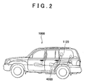
- a vehicle 1000 that is mounted with a battery pack using a mounting structure for a vehicular electrical equipment in accordance with the embodiment of the invention will be described with reference to Figs. 1 and 2 .
- the battery pack is cited as an example of the electrical equipment mounted in the vehicle 1000 in the following description, the invention is not limited to the example. Even if the electrical equipment is a fuel cell or the like instead of a battery pack, the mounting structure in accordance with the invention is applicable.
- batteries constituting the battery pack may be any of lead-acid batteries, lithium-ion batteries, and nickel-hydrogen batteries.
- the batteries constituting the battery pack may be different from any of the above-mentioned batteries.
- the battery pack is mounted below a rear seat.
- the battery pack may also be mounted below the front seat.
- a battery pack is composed of a plurality of modules, each of which is composed of a plurality of cells.
- One battery pack is divided into a plurality of units, each of which is composed of one or more modules. For instance, if one battery pack is composed of 30 modules each of which is composed of six cells, the battery pack is constituted by being divided into a first unit composed of 12 modules, a second unit composed of six modules, and a third unit composed of 12 modules.
- this vehicle 1000 is mounted with a right battery unit 2000 below a rear-right seat 1100.
- the right battery unit 2000 is part of the battery pack mounted in the vehicle 1000.
- a center battery unit 3000 is mounted below a rear-center seat 1110.
- a left battery unit 4000 is mounted below a left rear seat 1120.
- the battery pack is constructed such that the right battery unit 2000 as a single unit is formed of 12 modules, that the center battery unit 3000 as a single unit is formed of six modules, and that the left battery unit 4000 as a single unit is formed of 12 modules.
- the battery pack (which is divided into the right battery unit 2000, the center battery unit 3000, and the left battery unit 4000) that is mounted according to the mounting structure in accordance with the present embodiment is mounted below the rear seats 1100, 1110, and 1120.
- the rear seats 1100, 1110, and 1120 have a fold-down function. That is, if the rear seats 1100, 1110, and 1120 have their seat backs tilted down forwards, they are as high as a floor face of a luggage room.
- the fold-down function will be described with reference to Figs. 3A and 3B .
- the seat back of each of the rear-right seat 1100, the rear-center seat 1110, and the rear-left seat 1120 is unlocked by releasing a seat-fold stopper belt 1106.
- the seat back is thereby tilted down forwards.
- a link 1104 is tilted down forwards approximately by 90°, whereby a seating face and the seat back of each of the seats sink downwards.
- the fold-down function serves to equalize the height of a back face of the seat back with the height of the floor face of the luggage room, so that the floor face of the luggage room is flattened.
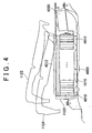
- Fig. 4 is a lateral view of the vehicle 1000 that is mounted with the battery pack using the mounting structure in accordance with the embodiment of the invention.
- the rear-left seat 1120 shown in Fig. 4 is viewed from the left side with respect to a forward direction of the vehicle.
- the rear-left seat 1120 in a normal service state is illustrated as a rear-left seat 1122, whereas the rear-left seat 1120 in a fold-down service state is illustrated as a rear-left seat 1124.
- Each of battery modules 4012 is formed below the rear-left seat 1120 by connecting a plurality of (e.g., six) battery cells 4010 in series.
- a plurality of the battery modules 4012 e.g., 12 modules
- the left battery unit 4000 is provided on a floor panel 1010, and is covered with a battery protection cover 4100 so as to be protected from the impact of an external object or the penetration of water contents.
- a cooling fan 4200 for cooling the left battery unit 4000 is installed.
- Fig. 5 is a rear view of the vehicle 1000 that is mounted with the battery pack using the battery-pack mounting structure in accordance with the embodiment of the invention.
- the right battery unit 2000, the center battery unit 3000, and the left battery unit 4000 are disposed below the rear-right seat 1100, the rear-center seat 1110, and the rear-left seat 1120 respectively.
- the left battery unit 4000 is installed between slide rails 5200 and 5300 for sliding the rear-left seat 1120 in a longitudinal direction of the vehicle.
- the rear-right seat 1100 and the rear-center seat 1110 shown in Fig. 5 slide together in the longitudinal direction.
- the right battery unit 2000 is installed between a seat rail 5000 and a seat rail 5100
- the center battery unit 3000 is installed between the seat rail 5100 and a seat rail 5200.
- the rear-right seat 1100 is fixed by a seat fixture jig 5002 and a seat fixture jig 5102, which are slidably provided on the seat rail 5000 and the seat rail 5100 respectively.
- the seat fixture jig 5002 and the seat fixture jig 5102 are provided in such a manner as to be slidable with respect to the seat rail 5000 and the seat rail 5100 respectively.
- the rear-right seat 1100 can thereby be slid in the longitudinal direction of the vehicle. At this moment, the rear-center seat 1110 also slides in the longitudinal direction, together with the rear-right seat 1100.
- the right battery unit 2000 is composed of a plurality of battery modules 2012 (e.g., 12 modules) that are arranged in a lateral direction of the vehicle 1000.
- Each of the battery modules 2012 is composed of a plurality of battery cells 2010 (e.g., six cells) that are connected in series. These battery modules 2012 are connected to one another in series.
- the center battery unit 3000 is composed of a plurality of battery modules 3012 (e.g., six modules) that are arranged in the lateral direction of the vehicle 1000.
- Each of the battery modules 3012 is composed of a plurality of battery cells 3010 (e.g., six cells) that are connected in series. These battery modules 3012 are connected to one another in series.
- the left battery unit 4000 is composed of a plurality of battery modules 4012 (e.g., 12 modules) that are arranged in the lateral direction of the vehicle 1000.
- Each of the battery modules 4012 is composed of a plurality of battery cells 4010 (e.g., six cells) that are connected in series. These battery modules 4012 are connected to one another in series.
- the right battery unit 2000, the center battery unit 3000, and the left battery unit 4000 are connected in series.
- the 30 modules are connected in series in the battery unit as a whole.
- the six cells are connected in series in each of the modules, the 180 cells are connected in series in the battery unit as a whole. If it is assumed that each of the cells outputs a voltage of 1.2V, the battery pack has a rated voltage of 216V.
- a system main relay and a current sensor 5600 are disposed below the seat rail 5100 and above the floor panel 1010 between the right battery unit 2000 and the center battery unit 3000.
- An ECU (electronic control unit) 5500 is installed below the seat rail 5200 and above the floor panel 1010 between the center battery unit 3000 and the left battery unit 4000.
- a fuel tank 6000 and a muffler 6100 are disposed below the floor panel 1010.
- the battery pack mounting structure in accordance with the embodiment is obtained by substantially flattening the upper convex shape of the floor panel 1011 of the vehicle in accordance with the related art. That is, the floor panel 1010 is smaller in height above ground level than the floor panel 1011 in accordance with the related art by a value corresponding to a top convex portion of the floor panel 1011. It has thus become possible to widen gaps between the floor panel 1010 and the seats 1100, 1110, and 1120.
- the floor panel 1010 is thus flattened.
- the seat rails 5000, 5100, and 5200 and a seat rail 5300 have been displaced upwards insofar as the fold-down function can be realized.
- the battery pack can be mounted in those gaps. Also, since gaps between the floor panel 1010 and the seat rails 5000, 5100, 5200, and 5300 have been widened, a control apparatus and the like can be disposed in those gaps. Even in the case where the battery pack, the control apparatus, and the like are thus mounted, the slide mechanism and the fold-down function of the seats can be realized.
- a battery pack composed of a plurality of battery cells or battery modules that are constructed according to the performance of a vehicle is divided into three battery units.
- the three units are respectively disposed at three positions formed by four seat rails that are provided to longitudinally slide right and left rear seats independently of each other. Each of the three positions is located between two corresponding ones of the four seat rails.
- the slide function of longitudinally adjusting positions of the seats is realized.
- the fold-down function is achieved while the seat rails are raised in position with a flattened floor panel.
Landscapes
- Engineering & Computer Science (AREA)
- Mechanical Engineering (AREA)
- Life Sciences & Earth Sciences (AREA)
- Sustainable Energy (AREA)
- Sustainable Development (AREA)
- Transportation (AREA)
- Chemical & Material Sciences (AREA)
- Power Engineering (AREA)
- Combustion & Propulsion (AREA)
- General Chemical & Material Sciences (AREA)
- Chemical Kinetics & Catalysis (AREA)
- Electrochemistry (AREA)
- Arrangement Or Mounting Of Propulsion Units For Vehicles (AREA)
- Body Structure For Vehicles (AREA)
- Battery Mounting, Suspending (AREA)
- Fuel Cell (AREA)
Claims (10)
- Fahrzeug mit einer elektrischen Fahrzeugeinrichtung und einer Bodenplatte (1010), wobei
die elektrische Einrichtung zwischen der Bodenplatte (1010) und einem Sitz (1100, 1110, 1120) montiert ist, der an der Bodenplatte (1010) angeordnet ist, und
eine Vielzahl von Sitzschienen (5000, 5100, 5200, 5300) an der Bodenplatte (1010) zum Montieren des Sitzes (1100, 1110, 1120) vorgesehen sind, so dass eine Position des Sitzes (1100, 1110, 1120) in einer Längsrichtung eines Fahrzeugs (1000) eingestellt werden kann,
wobei die elektrische Einrichtung ein Batteriepack aufweist,
dadurch gekennzeichnet, dass
die elektrische Einrichtung zwischen entsprechenden der Sitzschienen (5000, 5100, 5200, 5300) montiert ist, und wobei
das Batteriepack eine Vielzahl von Zellen oder Modulen gemäß einer Leistung des Fahrzeugs (1000) aufweist und konstruiert ist, indem sie in eine Vielzahl von Batterieeinheiten (2000, 3000, 4000) geteilt ist, von denen jede eine oder mehrere der Zellen oder der Module aufweist, und
wobei das Batteriepack so montiert ist, dass jede der Batterieeinheiten (2000, 3000, 4000) zwischen entsprechenden der Sitzschienen (5000, 5100, 5200, 5300) angeordnet ist. - Fahrzeug gemäß Anspruch 1, wobei ein Steuergerät zum Steuern des Batteriepacks zwischen entsprechenden der Batterieeinheiten (2000, 3000, 4000) angeordnet ist.
- Fahrzeug mit einer elektrischen Fahrzeugeinrichtung und einer Bodenplatte (1010), wobei
die elektrische Einrichtung zwischen der Bodenplatte (1010) und einem Sitz (1100, 1110, 1120) montiert ist, der an der Bodenplatte (1010) angeordnet ist, und
eine Vielzahl von Sitzschienen (5000, 5100, 5200, 5300) an der Bodenplatte (1010) zum Montieren des Sitzes (1100, 1110, 1120) vorgesehen ist, so dass eine Position des Sitzes (1100, 1110, 1120) in einer Längsrichtung eines Fahrzeugs (1000) eingestellt werden kann,
dadurch gekennzeichnet, dass
die elektrische Einrichtung zwischen entsprechenden der Sitzschienen (5000, 5100, 5200, 5300) montiert ist, und
die elektrische Einrichtung eine Brennstoffzellenbaugruppe aufweist, wobei
die Brennstoffzellenbaugruppe eine Vielzahl von Zellen oder Modulen gemäß einer Leistung des Fahrzeugs (1000) aufweist und konstruiert ist, indem sie in eine Vielzahl von Brennstoffzelleneinheiten geteilt ist, von denen jede eine oder mehrere der Zellen oder der Module aufweist, und
wobei die Brennstoffzellenbaugruppe so montiert ist, dass jede der Brennstoffzelleneinheiten zwischen entsprechenden der Sitzschienen (5000, 5100, 5200, 5300) angeordnet ist. - Fahrzeug gemäß Anspruch 3, wobei ein Steuergerät zum Steuern der Brennstoffzellenbaugruppe zwischen entsprechenden der Brennstoffzelleneinheiten angeordnet ist.
- Fahrzeug gemäß Anspruch 2 oder 4, wobei das Steuergerät zwischen den Sitzschienen (5000, 5100, 5200, 5300) und der Bodenplatte (1010) angeordnet ist.
- Fahrzeug gemäß einem der Ansprüche 1 bis 5, wobei der Sitz (1100, 1110, 1120) ein Rücksitz ist.
- Fahrzeug gemäß Anspruch 6, wobei der Rücksitz ein Sitz einer zweiten Reihe ist.
- Fahrzeug gemäß einem der Ansprüche 1 bis 7, wobei der Sitz (1100, 1110, 1120) ein Vordersitz ist.
- Fahrzeug gemäß einem der Ansprüche 1 bis 8, wobei der Sitz (1100, 1110, 1120) eine vertikal einstellbare Sitzfläche hat.
- Fahrzeug gemäß Anspruch 9, wobei der Sitz (1100, 1110, 1120) eine Umlegfunktion hat.
Applications Claiming Priority (3)
| Application Number | Priority Date | Filing Date | Title |
|---|---|---|---|
| JP2003035449 | 2003-02-13 | ||
| JP2003035449A JP4178986B2 (ja) | 2003-02-13 | 2003-02-13 | 車両用電気機器の搭載構造 |
| PCT/IB2004/000339 WO2004071798A1 (en) | 2003-02-13 | 2004-02-11 | Mounting structure for vehicular electrical equipment |
Publications (2)
| Publication Number | Publication Date |
|---|---|
| EP1592573A1 EP1592573A1 (de) | 2005-11-09 |
| EP1592573B1 true EP1592573B1 (de) | 2009-09-30 |
Family
ID=32866296
Family Applications (1)
| Application Number | Title | Priority Date | Filing Date |
|---|---|---|---|
| EP04710088A Expired - Lifetime EP1592573B1 (de) | 2003-02-13 | 2004-02-11 | Montagekonstruktion für elektrische fahrzeugeinrichtungen |
Country Status (7)
| Country | Link |
|---|---|
| US (1) | US7637335B2 (de) |
| EP (1) | EP1592573B1 (de) |
| JP (1) | JP4178986B2 (de) |
| KR (1) | KR100699564B1 (de) |
| CN (1) | CN100497022C (de) |
| DE (1) | DE602004023370D1 (de) |
| WO (1) | WO2004071798A1 (de) |
Cited By (1)
| Publication number | Priority date | Publication date | Assignee | Title |
|---|---|---|---|---|
| DE102022105511B3 (de) | 2022-03-09 | 2023-07-27 | Dr. Ing. H.C. F. Porsche Aktiengesellschaft | Fahrzeug mit einem Gaskanal zwischen einem Batteriesystem und einer Unterfahrschutzplatte |
Families Citing this family (33)
| Publication number | Priority date | Publication date | Assignee | Title |
|---|---|---|---|---|
| JP4061589B2 (ja) * | 2003-06-24 | 2008-03-19 | 日産自動車株式会社 | 燃料電池システム搭載車両 |
| JP4984404B2 (ja) * | 2005-03-03 | 2012-07-25 | 日産自動車株式会社 | 車両用電源ユニット |
| JP4774783B2 (ja) * | 2005-03-30 | 2011-09-14 | トヨタ自動車株式会社 | 駆動用電池パック搭載構造 |
| JP4415910B2 (ja) * | 2005-07-12 | 2010-02-17 | トヨタ自動車株式会社 | ハイブリッド車両の構造 |
| JP4826216B2 (ja) * | 2005-11-07 | 2011-11-30 | トヨタ自動車株式会社 | 燃料電池を搭載した車両 |
| JP2007238013A (ja) * | 2006-03-10 | 2007-09-20 | Toyota Motor Corp | 燃料電池自動車 |
| JP4940749B2 (ja) * | 2006-04-28 | 2012-05-30 | トヨタ自動車株式会社 | 電源装置の車両搭載構造 |
| JP4940783B2 (ja) * | 2006-06-28 | 2012-05-30 | 日産自動車株式会社 | 車両用バッテリパックの搭載構造 |
| JP4390802B2 (ja) * | 2006-12-15 | 2009-12-24 | トヨタ自動車株式会社 | 車載バッテリ冷却構造 |
| US7861812B2 (en) * | 2007-03-23 | 2011-01-04 | Honda Motor Co., Ltd. | Vehicle |
| JP2008279955A (ja) * | 2007-05-11 | 2008-11-20 | Toyota Motor Corp | 燃料電池搭載車両 |
| US9126477B2 (en) * | 2007-05-30 | 2015-09-08 | Ford Global Technologies, Llc | Ductless cooling system for a vehicle power storage unit |
| JP4225363B2 (ja) * | 2007-07-24 | 2009-02-18 | トヨタ自動車株式会社 | 内燃機関および回転電機を動力源として備える車両 |
| KR100937897B1 (ko) * | 2008-12-12 | 2010-01-21 | 주식회사 엘지화학 | 신규한 공냉식 구조의 중대형 전지팩 |
| CN102317097B (zh) * | 2009-02-24 | 2015-12-02 | 日产自动车株式会社 | 蓄电池搭载构造 |
| BRPI1008361A2 (pt) | 2009-02-24 | 2018-03-06 | Nissan Motor Co., Ltd. | estrutura de montagem de bateria para veículo |
| CN101544179B (zh) * | 2009-05-12 | 2012-08-22 | 奇瑞汽车股份有限公司 | 一种电动车用电池/电池组的安装结构 |
| WO2010150386A1 (ja) | 2009-06-25 | 2010-12-29 | トヨタ自動車株式会社 | ハイブリッド車の車両構造 |
| JP5461557B2 (ja) * | 2009-07-27 | 2014-04-02 | 本田技研工業株式会社 | 車両の電装部品搭載構造 |
| US8272685B2 (en) * | 2010-02-09 | 2012-09-25 | Ford Global Technologies, Llc | Vehicle seat with air duct |
| DE102010034925A1 (de) * | 2010-08-20 | 2012-02-23 | Gm Global Technology Operations Llc (N.D.Ges.D. Staates Delaware) | Energiespeicheranordnung im Bodenbereich eines Fahrzeugs |
| CN103987552B (zh) | 2011-10-11 | 2018-04-06 | 丰田自动车株式会社 | 蓄电装置的搭载结构 |
| EP2767428B1 (de) | 2011-10-13 | 2017-02-01 | Toyota Jidosha Kabushiki Kaisha | Struktur zur montage für eine stromspeichervorrichtung |
| JP5786777B2 (ja) * | 2012-03-22 | 2015-09-30 | トヨタ自動車株式会社 | 車両 |
| CN103264633B (zh) * | 2013-05-10 | 2016-07-13 | 奇瑞新能源汽车技术有限公司 | 一种电动汽车电池包的安装结构 |
| JP5645147B2 (ja) * | 2013-05-20 | 2014-12-24 | 三菱自動車工業株式会社 | 自動車の車体構造 |
| US9440509B2 (en) * | 2013-10-04 | 2016-09-13 | Ford Global Technologies, Llc | Battery cooling apparatus |
| JP5879323B2 (ja) | 2013-10-17 | 2016-03-08 | 富士重工業株式会社 | 電池パックの搭載構造 |
| US9033085B1 (en) * | 2014-02-20 | 2015-05-19 | Atieva, Inc. | Segmented, undercarriage mounted EV battery pack |
| KR102196066B1 (ko) | 2019-02-18 | 2020-12-29 | 한재연 | 화장품 원료로서의 기능성이 향상된 쇠비름 추출물 제조방법 |
| DE102019203042A1 (de) | 2019-03-06 | 2020-09-10 | Ford Global Technologies, Llc | Baugruppe mit Fahrzeugbatterie und Fahrzeugsitz für ein Hybridkraftfahrzeug |
| FR3104123A1 (fr) * | 2019-12-06 | 2021-06-11 | Renault S.A.S | Plancher avec protection de batterie sous siège avant. |
| JP7264070B2 (ja) * | 2020-01-20 | 2023-04-25 | トヨタ自動車株式会社 | 蓄電装置の搭載構造 |
Family Cites Families (21)
| Publication number | Priority date | Publication date | Assignee | Title |
|---|---|---|---|---|
| FR2698591B1 (fr) * | 1992-12-02 | 1995-02-17 | Peugeot | Banquette avant pour véhicule automobile. |
| JPH06199183A (ja) | 1992-12-28 | 1994-07-19 | Honda Motor Co Ltd | 電気自動車のコンソールボックス |
| US5704644A (en) | 1993-02-27 | 1998-01-06 | Esoro Ag | Lightweight road vehicle with strengthening structure |
| JP3045269B2 (ja) * | 1993-06-04 | 2000-05-29 | 本田技研工業株式会社 | 電気自動車の室内後部構造 |
| DE4412450A1 (de) * | 1994-04-12 | 1995-10-26 | Daimler Benz Ag | Anordnung eines Antriebsaggregats in einem Elektrofahrzeug |
| JP3420349B2 (ja) * | 1994-09-07 | 2003-06-23 | セイコーエプソン株式会社 | 電気自動車の電気動力ユニット及び動力伝達ユニット |
| US5957521A (en) * | 1995-03-22 | 1999-09-28 | Schlachter; Bradley S. | Underseat storage enclosure |
| GB9612932D0 (en) * | 1995-06-22 | 1996-08-21 | Glorywin Int Group Ltd | Battery controller |
| JP2971404B2 (ja) * | 1996-09-27 | 1999-11-08 | 本田技研工業株式会社 | 車両のシート構造 |
| JPH10109548A (ja) | 1996-10-09 | 1998-04-28 | Suzuki Motor Corp | 電気自動車のバッテリ取付構造 |
| JP3509517B2 (ja) * | 1997-12-18 | 2004-03-22 | 本田技研工業株式会社 | 電気自動車におけるバッテリおよび電気部品の冷却構造 |
| JPH11341608A (ja) | 1998-05-29 | 1999-12-10 | Honda Motor Co Ltd | 電気自動車 |
| JP4258876B2 (ja) | 1999-02-17 | 2009-04-30 | マツダ株式会社 | 車両用バッテリの冷却構造 |
| JP3817953B2 (ja) | 1999-02-22 | 2006-09-06 | マツダ株式会社 | 車両のバッテリ搭載構造 |
| JP3777981B2 (ja) * | 2000-04-13 | 2006-05-24 | トヨタ自動車株式会社 | 車両用電源装置 |
| US6264260B1 (en) * | 2000-07-25 | 2001-07-24 | Daimlerchrysler Corporation | Passive restraint and interlock system for interior mounted removable vehicular components |
| JP3405332B2 (ja) | 2000-09-14 | 2003-05-12 | トヨタ車体株式会社 | バッテリーハーネスの保護構造 |
| JP3598975B2 (ja) * | 2001-01-19 | 2004-12-08 | 日産自動車株式会社 | 燃料電池自動車の制御装置 |
| JP2003300419A (ja) | 2002-04-10 | 2003-10-21 | Toyota Motor Corp | 車両用バッテリ搭載構造 |
| US6902020B2 (en) * | 2002-07-29 | 2005-06-07 | Daimlerchrysler Corporation | Interior vehicle battery system and method |
| US7048321B2 (en) * | 2003-05-21 | 2006-05-23 | Honda Motor Co., Ltd. | High-voltage electrical equipment case arranging structure |
-
2003
- 2003-02-13 JP JP2003035449A patent/JP4178986B2/ja not_active Expired - Fee Related
-
2004
- 2004-02-11 KR KR1020057014809A patent/KR100699564B1/ko not_active IP Right Cessation
- 2004-02-11 EP EP04710088A patent/EP1592573B1/de not_active Expired - Lifetime
- 2004-02-11 US US10/544,340 patent/US7637335B2/en active Active
- 2004-02-11 WO PCT/IB2004/000339 patent/WO2004071798A1/en active Application Filing
- 2004-02-11 CN CNB2004800039171A patent/CN100497022C/zh not_active Expired - Fee Related
- 2004-02-11 DE DE602004023370T patent/DE602004023370D1/de not_active Expired - Lifetime
Cited By (1)
| Publication number | Priority date | Publication date | Assignee | Title |
|---|---|---|---|---|
| DE102022105511B3 (de) | 2022-03-09 | 2023-07-27 | Dr. Ing. H.C. F. Porsche Aktiengesellschaft | Fahrzeug mit einem Gaskanal zwischen einem Batteriesystem und einer Unterfahrschutzplatte |
Also Published As
| Publication number | Publication date |
|---|---|
| EP1592573A1 (de) | 2005-11-09 |
| US20060237248A1 (en) | 2006-10-26 |
| KR20050107423A (ko) | 2005-11-11 |
| US7637335B2 (en) | 2009-12-29 |
| JP2004243885A (ja) | 2004-09-02 |
| DE602004023370D1 (de) | 2009-11-12 |
| CN1747849A (zh) | 2006-03-15 |
| WO2004071798A1 (en) | 2004-08-26 |
| JP4178986B2 (ja) | 2008-11-12 |
| KR100699564B1 (ko) | 2007-03-23 |
| CN100497022C (zh) | 2009-06-10 |
Similar Documents
| Publication | Publication Date | Title |
|---|---|---|
| EP1592573B1 (de) | Montagekonstruktion für elektrische fahrzeugeinrichtungen | |
| JP7521661B2 (ja) | 電池搭載構造 | |
| EP1590841B1 (de) | Anordnung zum einbau von batterien in kraftfahrzeugen | |
| JP6118381B2 (ja) | 車載用バッテリー | |
| CN101263030B (zh) | 用于安装电气部件的结构 | |
| JP4390802B2 (ja) | 車載バッテリ冷却構造 | |
| US9849768B2 (en) | Vehicle body structure | |
| US20080149410A1 (en) | Arrangement structure of component parts for fuel cell vehicle | |
| JP4631177B2 (ja) | 車両用電池冷却装置 | |
| JP4023450B2 (ja) | 電気機器の冷却装置 | |
| JP2011079411A (ja) | 車両のバッテリ冷却構造 | |
| US20220305899A1 (en) | In-vehicle battery attachment structure | |
| JP5831343B2 (ja) | 電源装置を搭載した車両の外部給電用インバータの搭載構造 | |
| JP4691999B2 (ja) | 車両 | |
| JP4120484B2 (ja) | バッテリパックの冷却構造およびフロアボード | |
| CN115775943A (zh) | 电池模组及具备电池模组的电池包 | |
| EP4159513A1 (de) | Struktur zur entladung von batteriekühlluft | |
| JP4561083B2 (ja) | 車両用バッテリパックの搭載構造 | |
| JP2004311139A (ja) | バッテリパック搭載構造 | |
| CN214822945U (zh) | 汽车前舱和纯电动汽车 | |
| US20240308394A1 (en) | Vehicle | |
| Machida et al. | Development of Intelligent Power Unit for 2018 Model Year Accord Hybrid | |
| CN115805797A (zh) | 电池支承构造体 | |
| JP2022011590A (ja) | 電気自動車 | |
| JP2004311142A (ja) | バッテリパック搭載構造 |
Legal Events
| Date | Code | Title | Description |
|---|---|---|---|
| PUAI | Public reference made under article 153(3) epc to a published international application that has entered the european phase |
Free format text: ORIGINAL CODE: 0009012 |
|
| 17P | Request for examination filed |
Effective date: 20050728 |
|
| AK | Designated contracting states |
Kind code of ref document: A1 Designated state(s): AT BE BG CH CY CZ DE DK EE ES FI FR GB GR HU IE IT LI LU MC NL PT RO SE SI SK TR |
|
| AX | Request for extension of the european patent |
Extension state: AL LT LV MK |
|
| DAX | Request for extension of the european patent (deleted) | ||
| RBV | Designated contracting states (corrected) |
Designated state(s): DE FR GB |
|
| GRAP | Despatch of communication of intention to grant a patent |
Free format text: ORIGINAL CODE: EPIDOSNIGR1 |
|
| GRAS | Grant fee paid |
Free format text: ORIGINAL CODE: EPIDOSNIGR3 |
|
| GRAA | (expected) grant |
Free format text: ORIGINAL CODE: 0009210 |
|
| AK | Designated contracting states |
Kind code of ref document: B1 Designated state(s): DE FR GB |
|
| REG | Reference to a national code |
Ref country code: GB Ref legal event code: FG4D |
|
| REF | Corresponds to: |
Ref document number: 602004023370 Country of ref document: DE Date of ref document: 20091112 Kind code of ref document: P |
|
| PLBE | No opposition filed within time limit |
Free format text: ORIGINAL CODE: 0009261 |
|
| STAA | Information on the status of an ep patent application or granted ep patent |
Free format text: STATUS: NO OPPOSITION FILED WITHIN TIME LIMIT |
|
| 26N | No opposition filed |
Effective date: 20100701 |
|
| REG | Reference to a national code |
Ref country code: GB Ref legal event code: 746 Effective date: 20121112 |
|
| REG | Reference to a national code |
Ref country code: DE Ref legal event code: R084 Ref document number: 602004023370 Country of ref document: DE Effective date: 20121115 |
|
| REG | Reference to a national code |
Ref country code: FR Ref legal event code: PLFP Year of fee payment: 12 |
|
| PGFP | Annual fee paid to national office [announced via postgrant information from national office to epo] |
Ref country code: DE Payment date: 20150203 Year of fee payment: 12 |
|
| PGFP | Annual fee paid to national office [announced via postgrant information from national office to epo] |
Ref country code: GB Payment date: 20150211 Year of fee payment: 12 Ref country code: FR Payment date: 20150210 Year of fee payment: 12 |
|
| REG | Reference to a national code |
Ref country code: DE Ref legal event code: R119 Ref document number: 602004023370 Country of ref document: DE |
|
| GBPC | Gb: european patent ceased through non-payment of renewal fee |
Effective date: 20160211 |
|
| REG | Reference to a national code |
Ref country code: FR Ref legal event code: ST Effective date: 20161028 |
|
| PG25 | Lapsed in a contracting state [announced via postgrant information from national office to epo] |
Ref country code: FR Free format text: LAPSE BECAUSE OF NON-PAYMENT OF DUE FEES Effective date: 20160229 Ref country code: DE Free format text: LAPSE BECAUSE OF NON-PAYMENT OF DUE FEES Effective date: 20160901 Ref country code: GB Free format text: LAPSE BECAUSE OF NON-PAYMENT OF DUE FEES Effective date: 20160211 |