EP1590263B1 - Einstückiger doppelkammerbehälter - Google Patents
Einstückiger doppelkammerbehälter Download PDFInfo
- Publication number
- EP1590263B1 EP1590263B1 EP03815692A EP03815692A EP1590263B1 EP 1590263 B1 EP1590263 B1 EP 1590263B1 EP 03815692 A EP03815692 A EP 03815692A EP 03815692 A EP03815692 A EP 03815692A EP 1590263 B1 EP1590263 B1 EP 1590263B1
- Authority
- EP
- European Patent Office
- Prior art keywords
- container
- ampule
- auxiliary receptacle
- closure
- closure device
- Prior art date
- Legal status (The legal status is an assumption and is not a legal conclusion. Google has not performed a legal analysis and makes no representation as to the accuracy of the status listed.)
- Expired - Lifetime
Links
- 239000003708 ampul Substances 0.000 claims description 34
- 239000000654 additive Substances 0.000 claims description 15
- 230000000996 additive effect Effects 0.000 claims description 15
- 239000000463 material Substances 0.000 claims description 6
- 238000000926 separation method Methods 0.000 claims description 6
- 230000008878 coupling Effects 0.000 claims description 5
- 238000010168 coupling process Methods 0.000 claims description 5
- 238000005859 coupling reaction Methods 0.000 claims description 5
- 239000004033 plastic Substances 0.000 claims description 5
- 230000015572 biosynthetic process Effects 0.000 claims description 4
- 230000009969 flowable effect Effects 0.000 claims description 3
- 239000012530 fluid Substances 0.000 description 6
- 238000003860 storage Methods 0.000 description 5
- 239000000243 solution Substances 0.000 description 4
- 239000000126 substance Substances 0.000 description 4
- 239000003795 chemical substances by application Substances 0.000 description 3
- 239000004615 ingredient Substances 0.000 description 3
- 238000004519 manufacturing process Methods 0.000 description 3
- 206010053648 Vascular occlusion Diseases 0.000 description 2
- 239000003814 drug Substances 0.000 description 2
- 230000000694 effects Effects 0.000 description 2
- 230000036512 infertility Effects 0.000 description 2
- 238000000034 method Methods 0.000 description 2
- 239000000203 mixture Substances 0.000 description 2
- 238000000465 moulding Methods 0.000 description 2
- 239000002245 particle Substances 0.000 description 2
- 238000007666 vacuum forming Methods 0.000 description 2
- 238000003466 welding Methods 0.000 description 2
- 238000009455 aseptic packaging Methods 0.000 description 1
- 238000007664 blowing Methods 0.000 description 1
- 230000006735 deficit Effects 0.000 description 1
- 238000001802 infusion Methods 0.000 description 1
- 238000002347 injection Methods 0.000 description 1
- 239000007924 injection Substances 0.000 description 1
- 238000002372 labelling Methods 0.000 description 1
- 239000007788 liquid Substances 0.000 description 1
- 229920000642 polymer Polymers 0.000 description 1
- 238000007789 sealing Methods 0.000 description 1
- 229920001169 thermoplastic Polymers 0.000 description 1
- 239000004416 thermosoftening plastic Substances 0.000 description 1
Images

Classifications
-
- B—PERFORMING OPERATIONS; TRANSPORTING
- B65—CONVEYING; PACKING; STORING; HANDLING THIN OR FILAMENTARY MATERIAL
- B65D—CONTAINERS FOR STORAGE OR TRANSPORT OF ARTICLES OR MATERIALS, e.g. BAGS, BARRELS, BOTTLES, BOXES, CANS, CARTONS, CRATES, DRUMS, JARS, TANKS, HOPPERS, FORWARDING CONTAINERS; ACCESSORIES, CLOSURES, OR FITTINGS THEREFOR; PACKAGING ELEMENTS; PACKAGES
- B65D25/00—Details of other kinds or types of rigid or semi-rigid containers
- B65D25/02—Internal fittings
- B65D25/04—Partitions
- B65D25/08—Partitions with provisions for removing or destroying, e.g. to facilitate mixing of contents
-
- B—PERFORMING OPERATIONS; TRANSPORTING
- B65—CONVEYING; PACKING; STORING; HANDLING THIN OR FILAMENTARY MATERIAL
- B65D—CONTAINERS FOR STORAGE OR TRANSPORT OF ARTICLES OR MATERIALS, e.g. BAGS, BARRELS, BOTTLES, BOXES, CANS, CARTONS, CRATES, DRUMS, JARS, TANKS, HOPPERS, FORWARDING CONTAINERS; ACCESSORIES, CLOSURES, OR FITTINGS THEREFOR; PACKAGING ELEMENTS; PACKAGES
- B65D81/00—Containers, packaging elements, or packages, for contents presenting particular transport or storage problems, or adapted to be used for non-packaging purposes after removal of contents
- B65D81/32—Containers, packaging elements, or packages, for contents presenting particular transport or storage problems, or adapted to be used for non-packaging purposes after removal of contents for packaging two or more different materials which must be maintained separate prior to use in admixture
- B65D81/3205—Separate rigid or semi-rigid containers joined to each other at their external surfaces
-
- A—HUMAN NECESSITIES
- A61—MEDICAL OR VETERINARY SCIENCE; HYGIENE
- A61J—CONTAINERS SPECIALLY ADAPTED FOR MEDICAL OR PHARMACEUTICAL PURPOSES; DEVICES OR METHODS SPECIALLY ADAPTED FOR BRINGING PHARMACEUTICAL PRODUCTS INTO PARTICULAR PHYSICAL OR ADMINISTERING FORMS; DEVICES FOR ADMINISTERING FOOD OR MEDICINES ORALLY; BABY COMFORTERS; DEVICES FOR RECEIVING SPITTLE
- A61J1/00—Containers specially adapted for medical or pharmaceutical purposes
- A61J1/05—Containers specially adapted for medical or pharmaceutical purposes for collecting, storing or administering blood, plasma or medical fluids ; Infusion or perfusion containers
- A61J1/06—Ampoules or carpules
-
- B—PERFORMING OPERATIONS; TRANSPORTING
- B65—CONVEYING; PACKING; STORING; HANDLING THIN OR FILAMENTARY MATERIAL
- B65D—CONTAINERS FOR STORAGE OR TRANSPORT OF ARTICLES OR MATERIALS, e.g. BAGS, BARRELS, BOTTLES, BOXES, CANS, CARTONS, CRATES, DRUMS, JARS, TANKS, HOPPERS, FORWARDING CONTAINERS; ACCESSORIES, CLOSURES, OR FITTINGS THEREFOR; PACKAGING ELEMENTS; PACKAGES
- B65D1/00—Rigid or semi-rigid containers having bodies formed in one piece, e.g. by casting metallic material, by moulding plastics, by blowing vitreous material, by throwing ceramic material, by moulding pulped fibrous material or by deep-drawing operations performed on sheet material
- B65D1/09—Ampoules
- B65D1/095—Ampoules made of flexible material
-
- B—PERFORMING OPERATIONS; TRANSPORTING
- B65—CONVEYING; PACKING; STORING; HANDLING THIN OR FILAMENTARY MATERIAL
- B65D—CONTAINERS FOR STORAGE OR TRANSPORT OF ARTICLES OR MATERIALS, e.g. BAGS, BARRELS, BOTTLES, BOXES, CANS, CARTONS, CRATES, DRUMS, JARS, TANKS, HOPPERS, FORWARDING CONTAINERS; ACCESSORIES, CLOSURES, OR FITTINGS THEREFOR; PACKAGING ELEMENTS; PACKAGES
- B65D81/00—Containers, packaging elements, or packages, for contents presenting particular transport or storage problems, or adapted to be used for non-packaging purposes after removal of contents
- B65D81/32—Containers, packaging elements, or packages, for contents presenting particular transport or storage problems, or adapted to be used for non-packaging purposes after removal of contents for packaging two or more different materials which must be maintained separate prior to use in admixture
- B65D81/3277—Ampoules
-
- A—HUMAN NECESSITIES
- A61—MEDICAL OR VETERINARY SCIENCE; HYGIENE
- A61J—CONTAINERS SPECIALLY ADAPTED FOR MEDICAL OR PHARMACEUTICAL PURPOSES; DEVICES OR METHODS SPECIALLY ADAPTED FOR BRINGING PHARMACEUTICAL PRODUCTS INTO PARTICULAR PHYSICAL OR ADMINISTERING FORMS; DEVICES FOR ADMINISTERING FOOD OR MEDICINES ORALLY; BABY COMFORTERS; DEVICES FOR RECEIVING SPITTLE
- A61J1/00—Containers specially adapted for medical or pharmaceutical purposes
- A61J1/14—Details; Accessories therefor
- A61J1/20—Arrangements for transferring or mixing fluids, e.g. from vial to syringe
- A61J1/2003—Accessories used in combination with means for transfer or mixing of fluids, e.g. for activating fluid flow, separating fluids, filtering fluid or venting
- A61J1/202—Separating means
- A61J1/2027—Separating means having frangible parts
-
- A—HUMAN NECESSITIES
- A61—MEDICAL OR VETERINARY SCIENCE; HYGIENE
- A61J—CONTAINERS SPECIALLY ADAPTED FOR MEDICAL OR PHARMACEUTICAL PURPOSES; DEVICES OR METHODS SPECIALLY ADAPTED FOR BRINGING PHARMACEUTICAL PRODUCTS INTO PARTICULAR PHYSICAL OR ADMINISTERING FORMS; DEVICES FOR ADMINISTERING FOOD OR MEDICINES ORALLY; BABY COMFORTERS; DEVICES FOR RECEIVING SPITTLE
- A61J1/00—Containers specially adapted for medical or pharmaceutical purposes
- A61J1/14—Details; Accessories therefor
- A61J1/20—Arrangements for transferring or mixing fluids, e.g. from vial to syringe
- A61J1/2093—Containers having several compartments for products to be mixed
-
- Y—GENERAL TAGGING OF NEW TECHNOLOGICAL DEVELOPMENTS; GENERAL TAGGING OF CROSS-SECTIONAL TECHNOLOGIES SPANNING OVER SEVERAL SECTIONS OF THE IPC; TECHNICAL SUBJECTS COVERED BY FORMER USPC CROSS-REFERENCE ART COLLECTIONS [XRACs] AND DIGESTS
- Y10—TECHNICAL SUBJECTS COVERED BY FORMER USPC
- Y10S—TECHNICAL SUBJECTS COVERED BY FORMER USPC CROSS-REFERENCE ART COLLECTIONS [XRACs] AND DIGESTS
- Y10S206/00—Special receptacle or package
- Y10S206/82—Separable, striplike plural articles
-
- Y—GENERAL TAGGING OF NEW TECHNOLOGICAL DEVELOPMENTS; GENERAL TAGGING OF CROSS-SECTIONAL TECHNOLOGIES SPANNING OVER SEVERAL SECTIONS OF THE IPC; TECHNICAL SUBJECTS COVERED BY FORMER USPC CROSS-REFERENCE ART COLLECTIONS [XRACs] AND DIGESTS
- Y10—TECHNICAL SUBJECTS COVERED BY FORMER USPC
- Y10S—TECHNICAL SUBJECTS COVERED BY FORMER USPC CROSS-REFERENCE ART COLLECTIONS [XRACs] AND DIGESTS
- Y10S215/00—Bottles and jars
- Y10S215/08—Mixing
Definitions
- the invention relates to a container having an opening for dispensing contained in the container flowable or pourable materials and with a closure device closing the opening, which is removable to release the opening according to the feature configuration of claim 1.
- Containers of this type which are filled with ingredients to be dispensed, are known in various forms and for different uses of the dispensed ingredients. For example, they may be ampule-type containers containing pharmaceuticals to be dispensed from the container for injection, infusion, or the like.
- the respective removal opening is for both the ampoule and for the auxiliary container in a neck part, which is not part of the extension, and the neck parts are inclined towards each other with a predetermined removal angle, so that at a fluid removal from the container product, the fluid delivery outside of the same common place.
- a mixture of the container contents outside of the container can be carried out with essentially only one actuating step.
- the mixing of the fluid contents outside of the container product leads to an impairment of the sterility of the respective fluid, which was still guaranteed before delivery within the container.
- simultaneous manual operation of the ampule and the auxiliary container it is difficult to provide uniform fluid or media delivery, thus compromising the result of mixing outside of the container product.
- the two chambers of a dual-chamber container in particular a dual-chamber ampoule, by two juxtaposed and releasably interconnected ampoules with substantially the same Structure and formed with a jointly removable closure as a closure device for both ampoules.
- the one ampoule has a neck forming the filling and / or removal opening with a conical outer lateral surface tapering towards the free end of the neck, and the other ampoule has a neck forming the filling and / or removal opening with an inner cone corresponding to the one Outer cone of the other ampoule is formed and tapers towards the interior of the ampoule.
- a type of coupling sleeve is obtained for the formation of a sealed passage between the two ampoules. Furthermore, in turn, on the side facing away from the common closure device to the two ampoules joins a common extension with corresponding predetermined breaking points for the separation of the two ampoules from each other, wherein the extension serves as a grip surface and offers an opportunity for labeling the container product corresponding identification, for example, in the form of a label to install.
- This known, closest solution thus has a common closure device for both ampoules and said common extension in the form of the handle surface ends in the region of the neck portion of each ampoule, so that the closure device is not part of this extension.
- the invention has the object to provide a container which is improved over the known solutions and in particular allows a simplified storage and handling.
- the proposed releasable connection between the container and the auxiliary container containing the additive simplifies the storage, because both means, although they are separated from each other, form a storage unit.
- the handling required for the delivery of the substance is particularly simplified because the addition of the additive to the container contents is particularly simple and convenient in the way that the auxiliary container with its outlet device with the opening of the container can be coupled.
- the unit of container and auxiliary receptacle attached to its opening may be shaken to effect, for example, a required mixing of the two agents or, if the additive is a pourable agent of particular particle size, for example in the form of a single large particle, such as a tablet to effect passage through the passageway between the auxiliary container and the container.
- the container is advantageously after in the art as bottelpack ® - System produced by known methods. This method enables automated molding (blowing or vacuum forming), filling and sealing of containers in an economical manner.
- the container with its closure device and the auxiliary container with its closure made of plastic as a one-piece body are formed on the weak points that form predetermined breaking points at which the closure device of the container and the Auxiliary container for removal from the container can be separated. In the simplest way can thereby both open the container and remove the auxiliary container to handle this separately.
- a weak point is also formed on the outlet of the auxiliary container, which forms a predetermined breaking point for the separation of the closure of the auxiliary container for the release of the outlet device.
- the container is a type of ampoule, the opening of which is provided on a neck portion projecting coaxially with the ampoule main axis
- the body forming the unit of container and auxiliary container may be formed so as to extend in the direction of the neck area of the ampoule the ampoule main axis extending extension is extended, at which the closure device of the container, the auxiliary container and the weak points forming the predetermined breaking points are formed.
- This extension of the body may be formed in adjacent to the closure device of the container and to the closure of the auxiliary container portions in the form of flat plates, so that grip surfaces are formed by means of which the closure device and the auxiliary container can be easily separated by means of the predetermined breaking points of the container.
- the invention is illustrated by the example of an ampoule-like container, which is made in one piece according to the known in the art bottelpack ® system made of thermoplastic polymeric material.
- this method of manufacturing and filling containers at least one tube of plasticized plastic material is extruded into an open mold.
- the course of closing lower Moldings are performed on the hose welding operations to form the container bottom.
- the hose, or in the formation of a plurality of containers, the hoses, is or are cut above the mold to form a respective filling opening by means of a separating element.
- the mold is then moved with the unit having the open fill opening or open fill openings to a fill position in which the container (s), after being inflated by blown air or vacuum forming the container mold, is provided with the contents. Then, a head welding operation is performed on the top of the container or containers, thereby making the closure of the filled unit.
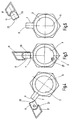
- Fig. 1 shows a unit manufactured according to the bottelpack ® system with a one-piece body designated as a whole by 1, at which the filled, ampoule-like container 3 forms the lower body end portion.
- the container 3 has a to the ampoule main axis 5 coaxially upwardly projecting neck portion 7 with the container opening 8.
- neck portion 7 he stretches in the direction of the main vial axis 5, a body extension 9 upwards, on which, as in Fig. 1 is shown, a closure of the opening 8 of the container forming closure device 11 and an auxiliary container 13 are formed as integral parts of the body extension 9.
- weak points 21 are formed, which form predetermined breaking points for the separation of the components and the case taking place taking off the closure device 11 of the container opening 8.
- FIGS. 2 and 3 show the body extension 9 subregions in the form of flat plates 15, 17 and 19. These form gripping surfaces, with the aid of which the components forming the body extension 9 can be removed from the break-off points of the ampule-type container 3 are.
- Fig. 2 shows the operating state in which the auxiliary container 13 is removed from the rest of the unit.
- Fig. 3 shows a next operating state in use, in which by means of the gripping surfaces 17 and 19 of the closure 23 of the auxiliary container 13 is removed by disconnecting at a respective predetermined breaking point to expose the outlet means 25 of the auxiliary container 13.
- Fig. 3 in that, with the aid of the gripping surface 15, the closure device 11 is separated from the neck region 7 of the container 3, in order to release its opening 8.
- Fig. 4 shows the following in use stage, in which the auxiliary container 13 is brought with the additive contained therein in the form of a tablet 27 to the opening 8 of the container 3 to pour the tablet 27 via the outlet means 25 and the opening 8 in the container 3 ,
- the outlet means 25 forms on the auxiliary container 13 to the neck portion 7 of the container 3 suitable, attachable to the neck portion 7 coupling sleeve 29, by means of which a sealed-to-outside passage between the auxiliary container 13 and the interior of the container 3 can be formed.
- the thus formed, reclosed unit can now be shaken to dissolve the input into the container 3 tablet 27 in the desired manner and to mix the so introduced into the container 3 additive with the rest of the container contents.
- Fig. 6 shows that after removing the auxiliary container 13 provided with the additive content of the container 3 can be output via the now exposed opening 8.
- auxiliary container 13 which is to be added to the contents of the container 3. It can also be seen that for the container 3 and the auxiliary container 13 other container shapes As shown in the drawing, can be provided and that instead of the aforementioned bottelpack ® system other manufacturing methods for forming the container and auxiliary container unit can be applied.
Landscapes
- Engineering & Computer Science (AREA)
- Mechanical Engineering (AREA)
- Health & Medical Sciences (AREA)
- Public Health (AREA)
- Animal Behavior & Ethology (AREA)
- General Health & Medical Sciences (AREA)
- Life Sciences & Earth Sciences (AREA)
- Veterinary Medicine (AREA)
- Pharmacology & Pharmacy (AREA)
- Ceramic Engineering (AREA)
- Hematology (AREA)
- Medical Preparation Storing Or Oral Administration Devices (AREA)
- Package Specialized In Special Use (AREA)
- Closures For Containers (AREA)
- Packages (AREA)
Description
- Die Erfindung bezieht sich auf einen Behälter mit einer Öffnung zur Abgabe von im Behälter befindlichen fließ- oder schüttfähigen Stoffen und mit einer die Öffnung verschließenden Verschlußeinrichtung, die zur Freigabe der Öffnung abnehmbar ist gemäß der Merkmalsausgestaltung des Patentanspruches 1.
- Behälter dieser Art, die mit abzugebenden Inhaltsstoffen befüllt sind, sind in verschiedensten Formen und für unterschiedliche Verwendungszwecke der abgegebenen Inhaltsstoffe bekannt. Beispielsweise kann es sich um ampullenartige Behälter handeln, die Pharmazeutika enthalten, die für Injektionszwecke, Infusionszwecke oder dergleichen aus dem Behälter abzugeben sind.
- Sowohl auf dem Gebiet medizinischer Anwendungen als auch bei allgemein technischen Anwendungen, bei denen aus einem Behälter abzugebende Inhaltsstoffe für Be- oder Verarbeitungsvorgänge benutzt werden, tritt teilweise das Problem auf, dass der abzugebende Stoff eine Zusammensetzung aus Mitteln ist, die hinsichtlich gemeinsamer Lagerungsfähigkeit inkompatibel sind. In anderen Worten gesagt, dürfen diese getrennt zu lagernden Mittel erst zu dem aus dem Behälter abzugebenden Stoff vereinigt werden, wenn die Benutzung dieses Zwei-Komponentenstoffes stattfindet. Das Erfordernis der getrennten Lagerung und der vor der Anwendung stattfindenden Vereinigung der Mittel führt in nachteiliger Weise zu einem erhöhten Lagerungsaufwand und umständlicher Handhabung.
- Zur Vermeidung der dahingehenden Problematik wurde durch die
US-B-6 247 617 bereits eine Behälterlösung vorgeschlagen mit einer Ampulle und einem Hilfsbehältnis, die als einstückiger Körper aus Kunststoff hergestellt sind und als weiteren Bestandteil einen sich in Richtung der Ampullen-Hauptachse erstreckenden Fortsatz aufweisen, der mindestens eine Grifffläche ausbildet, wobei auf der gegenüberliegenden Seite des Fortsatzes das Behältererzeugnis eine gemeinsame Verschlußeinrichtung dergestalt aufweist, dass nach Entfernen dieser Verschlußeinrichtung entlang mindestens einer Sollbruchstelle eine Entnahmeöffnung sowohl für die Ampulle als auch für das Hilfserzeugnis freigegeben ist. Die jeweilige Entnahmeöffnung geht sowohl für die Ampulle als auch für das Hilfsbehältnis in ein Halsteil über, das nicht Bestandteil des Fortsatzes ist, und die Halsteile sind mit einem vorgebbaren Entnahmewinkel aufeinander zugeneigt, so dass bei einer Fluidentnahme aus dem Behältererzeugnis die Fluidabgabe außerhalb desselben an einer gemeinsamen Stelle erfolgt. Auf diese Art und Weise kann mit nur einem Entnahmevorgang eine Mischung der Behälterinhalte außerhalb des Behälters mit im wesentlichen nur einem Betätigungsschritt erfolgen. Die Vermischung der Fluidinhalte außerhalb des Behältererzeugnisses führt jedoch zu einer Beeinträchtigung der Sterilität des jeweiligen Fluids, die vor Abgabe innerhalb des Behälters noch gewährleistet war. Auch ist bei gleichzeitiger Betätigung von Hand betreffend die Ampulle und das Hilfsbehältnis eine gleichmäßige Fluid- oder Medienabgabe nur schwer möglich, was insoweit das Ergebnis der Durchmischung außerhalb des Behältererzeugnisses beeinträchtigt. - Bei dem nächstkommenden Stand der Technik in Form der
DE 38 33 036 A werden die beiden Kammern eines Doppelkammerbehälters, insbesondere einer Doppelkammerampulle, durch zwei nebeneinander angeordnete und lösbar miteinander verbundene Ampullen mit im wesentlichen gleichem Aufbau und mit einem gemeinsam entfernbaren Verschluß als Verschlußeinrichtung für beide Ampullen gebildet. Dabei hat die eine Ampulle einen die Füll- und/oder Entnahmeöffnung bildenden Hals mit einer sich zum freien Ende des Halses hin verjüngenden konischen Außenmantelfläche und die andere Ampulle hat einen die Füll- und/oder Entnahmeöffnung bildenden Hals mit einem Innenkonus, der korrespondierend zu dem Außenkonus der anderen Ampulle ausgebildet ist und sich gegen das Innere der Ampulle hin verjüngt. Durch die korrespondierende Ausgestaltung von Innenkonus und Außenkonus ist eine Art Kupplungsmuffe erhalten für die Bildung eines abgedichteten Durchganges zwischen den beiden Ampullen. Des weiteren schließt sich wiederum auf der der gemeinsamen Verschlußeinrichtung abgewandten Seite an die beiden Ampullen ein gemeinsamer Fortsatz mit entsprechenden Sollbruchstellen für das Abtrennen der beiden Ampullen voneinander an, wobei der Fortsatz als Grifffläche dient und eine Möglichkeit bietet, zur Kennzeichnung des Behältererzeugnisses eine entsprechende Kennzeichnung, beispielsweise in Form einer Beschriftung, anzubringen. - Diese bekannte, nächstkommende Lösung weist mithin eine gemeinsame Verschlußeinrichtung für beide Ampullen auf und der genannte gemeinsame Fortsatz in Form der Grifffläche endet im Bereich des Halsteils einer jeden Ampulle, so dass die Verschlußeinrichtung nicht Bestandteil dieses Fortsatzes ist.
- Bei dieser bekannten Lösung ist nicht auszuschließen, dass sich die Verschlußeinrichtung ungewollt von der jeweiligen Behälteröffnung abtrennt und im normalen Bedienfall gibt jedenfalls durch Entfernen der gemeinsamen Verschlußeinrichtung diese gleichzeitig beide Entnahmeöffnungen frei, was wiederum die Sterilität beeinträchtigt, bevor die bevorrateten Fluidmedien durch Zusammenstecken der Ampullen über die Kupplungsmuffe miteinander vermischt werden können.
- Ausgehend von diesem Stand der Technik stellt sich die Erfindung die Aufgabe, einen Behälter zu schaffen, der gegenüber den bekannten Lösungen verbessert ist und insbesondere eine vereinfachte Lagerung und Handhabung ermöglicht.
- Der erfindungsgemäße Behälter ist mit einer Öffnung zur Abgabe von im Behälter befindlichen fließ- oder schüttfähigen Stoffen und mit einer die Öffnung verschließenden Verschlußeinrichtung versehen, die zur Freigabe der Öffnung abnehmbar ist, wobei
- ein zur Aufnahme eines dem Inhalt des Behälters beizufügenden Zusatzstoffes vorgesehenes Hilfsbehältnis am Behälter abnehmbar angebracht ist, welches eine durch Abnehmen eines Verschlusses freigebbare Auslaßeinrichtung für den Austritt des Zusatzstoffes aufweist,
- das Hilfsbehältnis mit seiner freigegebenen Auslaßeinrichtung an der Öffnung des Behälters nach Abnehmen von dessen Verschlußeinrichtung anbringbar ist, um für die Beifügung des Zusatzstoffes einen nach außen abgedichteten Durchgang zwischen Hilfsbehältnis und Behälter zu bilden,
- der Behälter mit seiner Verschlußeinrichtung und das Hilfsbehältnis mit seinem Verschluß aus Kunststoff als einstückiger Körper hergestellt sind, an dem Schwachstellen ausgeformt sind, die Sollbruchstellen bilden, an denen die Verschlußeinrichtung des Behälters und das Hilfsbehältnis zum Abnehmen vom Behälter abtrennbar sind, wobei das Hilfsbehältnis (13) derart von der übrigen Einheit abnehmbar ist, dass sowohl der Behälter (3) als auch das Hilfsbehältnis (13) verschlossen bleiben,
- an der Auslaßeinrichtung des Hilfsbehältnisses eine Schwachstelle ausgeformt ist, die eine Sollbruchstelle für das Abtrennen des Verschlusses zur Freigabe der Auslaßeinrichtung bildet,
- der Behälter in der Art einer Ampulle ausgebildet ist, deren Öffnung an einem koaxial zur Ampullenhauptachse vorspringenden Halsteil vorgesehen ist,
- der Körper am Halsbereich der Ampulle durch einen sich in Richtung der Ampullenhauptachse erstreckenden Fortsatz verlängert ist, an dem die Verschlußeinrichtung der Ampulle, das Hilfsbehältnis sowie die die Sollbruchstellen bildenden Schwachstellen ausgeformt sind, und
- die freigegebene Auslaßeinrichtung des Hilfsbehältnisses die Form einer auf den Halsteil der Ampulle aufsteckbaren Kupplungsmuffe für die Bildung des abgedichteten Durchganges zwischen Hilfsbehältnis und Ampulle bildet.
- Durch die vorgesehene lösbare Verbindung zwischen Behälter und dem den Zusatzstoff enthaltenden Hilfsbehältnis vereinfacht sich die Lagerung, weil beide Mittel, obgleich sie voneinander getrennt sind, eine Lagerungseinheit bilden. Die zur Abgabe des Stoffes erforderliche Handhabung ist in besonderem Maße vereinfacht, weil die Beifügung des Zusatzstoffes zum Behälterinhalt besonders einfach und bequem in der Weise erfolgt, dass das Hilfsbehältnis mit seiner Auslaßeinrichtung mit der Öffnung des Behälters kuppelbar ist. Die Einheit aus Behälter und an dessen Öffnung angebrachtem Hilfsbehältnis kann geschüttelt werden, um beispielsweise eine erforderliche Vermengung der beiden Mittel herbeizuführen oder, wenn es sich bei dem Zusatzstoff um ein schüttbares Mittel bestimmter Partikelgröße handelt, beispielsweise in Form eines einzigen großen Partikels, etwa einer Tablette, das Durchtreten durch den Durchgang zwischen Hilfsbehältnis und Behälter zu bewirken.
- Wenn es sich bei den abzugebenden Stoffen um hochsensible Erzeugnisse handelt, wie dies bei Pharmazeutika der Fall ist, wo die internationalen Standards für die aseptische Verpackung zu erfüllen sind, dann wird der Behälter in vorteilhafter Weise nach dem in der einschlägigen Technik als bottelpack® - System bekannten Verfahren hergestellt. Dieses Verfahren ermöglicht ein automatisiertes Formen (Blasen oder Vakuumformen), Füllen und Verschließen von Behältnissen auf wirtschaftliche Weise.
- Entsprechend diesem System, oder auch bei Anwendung eines anderen Herstellungsverfahrens, wird vorzugsweise der Behälter mit seiner Verschlußeinrichtung und das Hilfsbehältnis mit seinem Verschluß aus Kunststoff als einstückiger Körper hergestellt, an dem Schwachstellen ausgeformt sind, die Sollbruchstellen bilden, an denen die Verschlußeinrichtung des Behälters und das Hilfsbehältnis zum Abnehmen vom Behälter abtrennbar sind. Auf einfachste Weise lassen sich dadurch sowohl der Behälter öffnen als auch das Hilfsbehältnis abnehmen, um dieses getrennt handhaben zu können.
- Vorzugsweise ist auch an der Auslaßeinrichtung des Hilfsbehältnisses eine Schwachstelle ausgeformt, die eine Sollbruchstelle für das Abtrennen des Verschlusses des Hilfsbehältnisses für die Freigabe von dessen Auslaßeinrichtung bildet.
- Wenn es sich bei dem Behälter um eine Art Ampulle handelt, deren Öffnung an einem koaxial zur Ampullenhauptachse vorspringenden Halsteil vorgesehen ist, dann kann der die Einheit aus Behälter und Hilfsbehältnis bildende Körper so ausgebildet sein, dass er am Halsbereich der Ampulle durch einen sich in Richtung der Ampullenhauptachse erstreckenden Fortsatz verlängert ist, an dem die Verschlußeinrichtung des Behälters, das Hilfsbehältnis sowie die die Sollbruchstellen bildenden Schwachstellen ausgeformt sind.
- Dieser Fortsatz des Körpers kann in an die Verschlußeinrichtung des Behälters und an den Verschluß des Hilfsbehältnisses angrenzenden Teilbereichen in Form ebener Platten ausgebildet sein, so dass Griffflächen gebildet werden, mit deren Hilfe die Verschlußeinrichtung sowie das Hilfsbehältnis mittels der Sollbruchstellen bequem vom Behälter abgetrennt werden können.
- Nachstehend ist die Erfindung anhand eines in der Zeichnung dargestellten Ausführungsbeispieles im einzelnen erläutert. Es zeigen:
-
Fig. 1 eine schematisch vereinfacht gezeichnete Seitenansicht eines Ausführungsbeispieles des erfindungsgemäßen Behälters in Form einer Ampulle mit einem an ihr befindlichen Hilfsbehältnis, das einen Zusatzstoff in Form einer Tablette enthält, und -
Fig. 2 bis 6 Darstellungen des Ausführungsbeispieles vonFig.1 , wobei die Bestandteile des Ausführungsbeispieles in unterschiedlichen Betriebszuständen gezeigt sind, die aufeinanderfolgenden Handhabungsschritten bei der Benutzung des Behälters entsprechen. - Unter Bezugnahme auf die Fig. wird die Erfindung am Beispiel eines ampullenartigen Behälters erläutert, der nach dem in der einschlägigen Technik bekannten bottelpack®-System aus thermoplastischem Kunststoffwerkstoff einstückig hergestellt ist. Bei diesem Verfahren zum Herstellen und Befüllen von Behältern wird zumindest ein Schlauch plastifizierten Kunststoffmaterials in eine geöffnete Form hinein extrudiert. Im Zuge des Schließens unterer Formteile werden am Schlauch Schweißvorgänge zur Bildung des Behälterbodens durchgeführt. Der Schlauch, oder bei Bildung mehrerer Behälter die Schläuche, wird bzw. werden oberhalb der Form zur Bildung einer betreffenden Füllöffnung mittels eines Trennelementes durchtrennt. Die Form wird sodann mit der die offene Füllöffnung oder die offenen Füllöffnungen aufweisenden Einheit in eine Füllposition bewegt, in welcher der oder die Behälter, nachdem durch Aufweiten mittels Blasluft oder Vakuumformen die Behälterform gebildet ist, mit dem Füllgut versehen wird. Sodann wird an der Oberseite des Behälters oder der Behälter ein Kopf-Schweißvorgang durchgeführt, wodurch der Verschluß der gefüllten Einheit hergestellt wird.
-
Fig. 1 zeigt eine entsprechend dem bottelpack®-System gefertigte Einheit mit einem als Ganzes mit 1 bezeichneten einstückigen Körper, an dem der gefüllte, ampullenartige Behälter 3 den unteren Körper-Endteil bildet. Der Behälter 3 weist einen zur Ampullenhauptachse 5 koaxial nach oben vorspringenden Halsteil 7 mit der Behälteröffnung 8 auf. Am Halsteil 7 er streckt sich in Richtung der Ampullenhauptachse 5 ein Körperfortsatz 9 nach oben, an dem, wie inFig. 1 gezeigt ist, eine den Verschluß der Öffnung 8 des Behälters bildende Verschlußeinrichtung 11 sowie ein Hilfsbehältnis 13 als integrale Bestandteile des Körperfortsatzes 9 ausgeformt sind. Zwischen den Bestandteilen des Körperfortsatzes 9 sind Schwachstellen 21 ausgeformt, die Sollbruchstellen für das Trennen der Bestandteile und des hierbei erfolgenden Abnehmens der Verschlußeinrichtung 11 von der Behälteröffnung 8 bilden. - Wie aus
Fig. 2 und 3 am deutlichsten zu ersehen ist, weist der Körperfortsatz 9 Teilbereiche in Form ebener Platten 15, 17 und 19 auf. Diese bilden Griffflächen, mit deren Hilfe die den Körperfortsatz 9 bildenden Bestandteile vom an den Sollbruchstellen vom ampullenartigen Behälter 3 abnehmbar sind.Fig. 2 zeigt den Betriebszustand, bei dem das Hilfsbehältnis 13 von der übrigen Einheit abgenommen ist.Fig. 3 zeigt einen bei Benutzung nächstfolgenden Betriebszustand, bei dem mittels der Griffflächen 17 und 19 der Verschluß 23 des Hilfsbehältnisses 13 durch Abtrennen an einer betreffenden Sollbruchstelle abgenommen ist, um die Auslaßeinrichtung 25 des Hilfsbehältnisses 13 freizulegen. Außerdem zeigtFig. 3 , dass mit Hilfe der Grifffläche 15 die Verschlußeinrichtung 11 vom Halsbereich 7 des Behälters 3 abgetrennt ist, um dessen Öffnung 8 freizugeben. -
Fig. 4 zeigt das bei der Benutzung folgende Stadium, bei dem das Hilfsbehältnis 13 mit dem darin enthaltenen Zusatzstoff in Form einer Tablette 27 an die Öffnung 8 des Behälters 3 herangebracht ist, um die Tablette 27 über die Auslaßeinrichtung 25 und die Öffnung 8 in den Behälter 3 einzuschütten. Wie ausFig. 5 zu ersehen ist, bildet die Auslaßeinrichtung 25 am Hilfsbehältnis 13 eine zum Halsteil 7 des Behälters 3 passende, auf den Halsteil 7 aufsteckbare Kupplungsmuffe 29, mittels deren ein nach außen abgedichteter Durchgang zwischen Hilfsbehältnis 13 und dem Innenraum des Behälters 3 gebildet werden kann. Die so gebildete, wieder verschlossene Einheit kann nun geschüttelt werden, um die in den Behälter 3 eingegebene Tablette 27 in gewünschter Weise aufzulösen und den so in den Behälter 3 eingebrachten Zusatzstoff mit dem übrigen Behälterinhalt zu vermischen.Fig. 6 zeigt, dass nach Abnehmen des Hilfsbehältnisses 13 der mit dem Zusatzstoff versehene Inhalt des Behälters 3 über die nun freigelegte Öffnung 8 ausgegeben werden kann. - Es versteht sich, dass an Stelle der als Zusatzstoff gezeigten Tablette 27 ein anderer, schüttbarer oder flüssiger Zusatzstoff im Hilfsbehältnis 13 vorgesehen sein kann, der dem Inhalt des Behälters 3 beizufügen ist. Es ist auch ersichtlich, dass für den Behälter 3 und das Hilfsbehältnis 13 andere Behälterformen als sie in der Zeichnung dargestellt sind, vorgesehen sein können und dass an Stelle des erwähnten bottelpack®-Systems andere Herstellungsverfahren zur Bildung der aus Behälter und Hilfsbehältnis bestehenden Einheit angewendet werden können.
Claims (4)
- Behälter (3) mit einer Öffnung (8) zur Abgabe von im Behälter (3) befindlichen fließ- oder schüttfähigen Stoffen und mit einer die Öffnung (8) verschließenden Verschlußeinrichtung (11), die zur Freigabe der Öffnung (8) abnehmbar ist, wobei- ein zur Aufnahme eines dem Inhalt des Behälters (3) beizufügenden Zusatzstoffes (27) vorgesehenes Hilfsbehältnis (13) am Behälter (3) abnehmbar angebracht ist, welches eine durch Abnehmen eines Verschlusses (23) freigebbare Auslaßeinrichtung (25) für den Austritt des Zusatzstoffes (27) aufweist,- das Hilfsbehältnis (13) mit seiner freigegebenen Auslaßeinrichtung (25) an der Öffnung (8) des Behälters (3) nach Abnehmen von dessen Verschlußeinrichtung (11) anbringbar ist, um für die Beifügung des Zusatzstoffes (27) einen nach außen abgedichteten Durchgang zwischen Hilfsbehältnis (13) und Behälter (3) zu bilden,- der Behälter (3) mit seiner Verschlußeinrichtung (11) und das Hilfsbehältnis (13) mit seinem Verschluß (23) aus Kunststoff als einstückiger Körper (1) hergestellt sind, an dem Schwachstellen (21) ausgeformt sind, die Sollbruchstellen bilden, an denen die Verschlußeinrichtung (11) des Behälters (3) und das Hilfsbehältnis (13) zum Abnehmen vom Behälter (3) abtrennbar sind,- an der Auslaßeinrichtung (25) des Hilfsbehältnisses (13) eine Schwachstelle (21) ausgeformt ist, die eine Sollbruchstelle für das Abtrennen des Verschlusses (23) zur Freigabe der Auslaßeinrichtung (25) bildet,- der Behälter in der Art einer Ampulle (3) ausgebildet ist, deren Öffnung (8) an einem koaxial zur Ampullenhauptachse (15) vorspringenden Halsteil (7) vorgesehen ist,- die freigegebene Auslaßeinrichtung (25) des Hilfsbehältnisses (13) die Form einer auf den Halsteil (7) der Ampulle (3) aufsteckbaren Kupplungsmuffe (29) für die Bildung des abgedichteten Durchganges zwischen Hilfsbehältnis (13) und Ampulle (3) bildet, dadurch gekennzeichnet, dass der Körper (1) am Halsbereich (7) der Ampulle (3) durch einen sich in Richtung der Ampullenhauptachse (5) erstreckenden Fortsatz (9) verlängert ist, an dem die Verschlußeinrichtung (11) der Ampulle (3), das Hilfsbehältnis (13) sowie die die Sollbruchstellen bildenden Schwachstellen (21) ausgeformt sind, und das Hilfsbehältnis (13) derart von der übrigen Einheit abnehmbar ist, dass sowohl der Behälter (3) als auch das Hilfsbehältnis (13) verschlossen bleiben.
- Behälter nach Anspruch 1, dadurch gekennzeichnet, dass der Fortsatz (9) des Körpers sich in zur Ampullenhauptachse (5) senkrechter Richtung über eine Breite erstreckt, die der Breite der Ampulle (3) entspricht.
- Behälter nach Anspruch 2, dadurch gekennzeichnet, dass der Fortsatz (9) des Körpers in an die Verschlußeinrichtung (11) der Ampulle (3) und an den Verschluß (23) des Hilfsbehältnisses (13) angrenzenden Teilbereichen in Form ebener Platten (15, 17, 19) ausgebildet ist, die Griffflächen bilden, mit deren Hilfe die Verschlußeinrichtung (11) und das Hilfsbehältnis (13) durch Trennen der Sollbruchstellen bequem von der Ampulle (3) abnehmbar ist.
- Behälter nach Anspruch 3, dadurch gekennzeichnet, dass eine Grifffläche (19) am Hilfsbehältnis (13) für das Abnehmen des Verschlusses (23) von der Auslaßeinrichtung (25) vorgesehen ist.
Applications Claiming Priority (3)
| Application Number | Priority Date | Filing Date | Title |
|---|---|---|---|
| DE10304500 | 2003-02-05 | ||
| DE2003104500 DE10304500A1 (de) | 2003-02-05 | 2003-02-05 | Behälter |
| PCT/EP2003/012677 WO2004069686A1 (de) | 2003-02-05 | 2003-11-13 | Einstrückiger doppelkammerbehälter |
Publications (2)
| Publication Number | Publication Date |
|---|---|
| EP1590263A1 EP1590263A1 (de) | 2005-11-02 |
| EP1590263B1 true EP1590263B1 (de) | 2013-02-20 |
Family
ID=32747552
Family Applications (1)
| Application Number | Title | Priority Date | Filing Date |
|---|---|---|---|
| EP03815692A Expired - Lifetime EP1590263B1 (de) | 2003-02-05 | 2003-11-13 | Einstückiger doppelkammerbehälter |
Country Status (14)
| Country | Link |
|---|---|
| US (1) | US7537131B2 (de) |
| EP (1) | EP1590263B1 (de) |
| JP (1) | JP4343849B2 (de) |
| KR (1) | KR20050099988A (de) |
| CN (1) | CN100423998C (de) |
| AU (1) | AU2003303858B2 (de) |
| BR (1) | BR0318089B1 (de) |
| CA (1) | CA2513800C (de) |
| DE (1) | DE10304500A1 (de) |
| ES (1) | ES2400463T3 (de) |
| MX (1) | MXPA05008376A (de) |
| PL (1) | PL202756B1 (de) |
| PT (1) | PT1590263E (de) |
| WO (1) | WO2004069686A1 (de) |
Families Citing this family (6)
| Publication number | Priority date | Publication date | Assignee | Title |
|---|---|---|---|---|
| AU2007332132B2 (en) * | 2006-12-15 | 2013-02-21 | Romuald Yip | A container to receive liquids to aid in the volumetric measuring of the liquids |
| US20110174665A1 (en) * | 2007-04-27 | 2011-07-21 | Daiwa Can Company | Polyester Resin Container With Fracturable Portion And Its Production Method |
| US8464918B1 (en) * | 2010-01-29 | 2013-06-18 | Unicep Packaging, Inc. | Child resistant closure for unit-dose packaging |
| JP5916067B2 (ja) * | 2011-10-28 | 2016-05-11 | 株式会社大塚製薬工場 | プラスチックアンプル |
| DE102012007165B4 (de) | 2012-04-07 | 2017-06-14 | Manfred Völker | Saures Dialysekonzentrat |
| IT202100004871A1 (it) * | 2021-03-02 | 2022-09-02 | Brev Angela Srl | Contenitore realizzato tramite un sistema per la formatura e relativo metodo di produzione |
Family Cites Families (16)
| Publication number | Priority date | Publication date | Assignee | Title |
|---|---|---|---|---|
| US3809289A (en) * | 1971-12-20 | 1974-05-07 | Automatic Liquid Packaging | Mixing containers |
| DE2638561A1 (de) * | 1976-08-26 | 1978-03-02 | Hago Chemie Gmbh & Co | Vorrichtung zur getrennten aufbewahrung und anschliessenden vermischung fliessfaehiger und/oder loeslicher stoffe |
| US4266681A (en) * | 1977-02-28 | 1981-05-12 | Oceanography International Corporation | Multiple breakpoint resealable ampoule |
| DE3833036C2 (de) * | 1988-09-29 | 1998-03-19 | Bernd Hansen | Doppelkammerbehälter |
| US4964539A (en) | 1989-04-06 | 1990-10-23 | Seaquist Closures | Multiple chamber dispensing container and closure system |
| DE4011671C2 (de) * | 1990-04-11 | 1994-04-28 | Glyco Metall Werke | Regelbare Flügelzellenpumpe |
| US5114011A (en) * | 1990-08-31 | 1992-05-19 | Robbins Edward S Iii | Container assemblies with additive cups |
| DE4405965C2 (de) * | 1994-02-24 | 1997-08-07 | Bernd Hansen | Infusionsbehälter mit zwei Anschlüssen |
| US5965164A (en) * | 1994-10-28 | 1999-10-12 | Fuisz Technologies Ltd. | Recipient-dosage delivery system |
| US5826737A (en) * | 1996-02-20 | 1998-10-27 | Colgate-Palmolive Company | Thermoformed reclosable container |
| US5897009A (en) * | 1996-10-18 | 1999-04-27 | Wheaton Usa, Inc. | One-piece container closure assemblies |
| US6022134A (en) * | 1996-10-25 | 2000-02-08 | Rxi Plastics, Inc. | Mixing and dispensing container |
| DE19706932A1 (de) * | 1997-02-20 | 1998-08-27 | Dentaco Gmbh | Mehrkammer-Ampulle für portionierte Flüssigkeiten |
| US6263923B1 (en) * | 1999-05-28 | 2001-07-24 | James A. Castillo | Device for maintaining separate ingredients in liquid food products |
| DE19958920C2 (de) * | 1999-12-07 | 2003-03-20 | Automation Industrielle Sa | Zweikammerbehälter |
| US6247617B1 (en) * | 1999-12-13 | 2001-06-19 | Richard Allen Clyde | Single use container for dispensing separately housed sterile compositions |
-
2003
- 2003-02-05 DE DE2003104500 patent/DE10304500A1/de not_active Withdrawn
- 2003-11-13 JP JP2004567747A patent/JP4343849B2/ja not_active Expired - Fee Related
- 2003-11-13 EP EP03815692A patent/EP1590263B1/de not_active Expired - Lifetime
- 2003-11-13 CA CA2513800A patent/CA2513800C/en not_active Expired - Fee Related
- 2003-11-13 PL PL376643A patent/PL202756B1/pl unknown
- 2003-11-13 AU AU2003303858A patent/AU2003303858B2/en not_active Ceased
- 2003-11-13 WO PCT/EP2003/012677 patent/WO2004069686A1/de not_active Ceased
- 2003-11-13 PT PT38156923T patent/PT1590263E/pt unknown
- 2003-11-13 BR BRPI0318089-1A patent/BR0318089B1/pt active IP Right Grant
- 2003-11-13 US US10/543,591 patent/US7537131B2/en not_active Expired - Lifetime
- 2003-11-13 ES ES03815692T patent/ES2400463T3/es not_active Expired - Lifetime
- 2003-11-13 MX MXPA05008376A patent/MXPA05008376A/es active IP Right Grant
- 2003-11-13 CN CNB2003801095600A patent/CN100423998C/zh not_active Expired - Fee Related
- 2003-11-13 KR KR1020057014358A patent/KR20050099988A/ko not_active Ceased
Also Published As
| Publication number | Publication date |
|---|---|
| AU2003303858B2 (en) | 2009-12-10 |
| CA2513800C (en) | 2010-04-20 |
| BR0318089B1 (pt) | 2014-12-30 |
| MXPA05008376A (es) | 2005-11-04 |
| PL202756B1 (pl) | 2009-07-31 |
| KR20050099988A (ko) | 2005-10-17 |
| ES2400463T3 (es) | 2013-04-10 |
| JP4343849B2 (ja) | 2009-10-14 |
| BR0318089A (pt) | 2005-12-20 |
| CN1745023A (zh) | 2006-03-08 |
| EP1590263A1 (de) | 2005-11-02 |
| US20060144853A1 (en) | 2006-07-06 |
| AU2003303858A1 (en) | 2004-08-30 |
| HK1087676A1 (zh) | 2006-10-20 |
| PT1590263E (pt) | 2013-04-02 |
| PL376643A1 (pl) | 2006-01-09 |
| JP2006513933A (ja) | 2006-04-27 |
| CN100423998C (zh) | 2008-10-08 |
| WO2004069686A1 (de) | 2004-08-19 |
| US7537131B2 (en) | 2009-05-26 |
| DE10304500A1 (de) | 2004-08-26 |
| CA2513800A1 (en) | 2004-08-19 |
Similar Documents
| Publication | Publication Date | Title |
|---|---|---|
| EP1246765B1 (de) | Adapter, anordnung und verfahren zur stoffentnahme aus mehrkammerschlauchbeuteln, verwendung des adapters sowie schlauchbeutelverpackung | |
| DE69303434T2 (de) | Behälter für pharmazeutische Produkte aus zwei gesonderten Komponenten, mit Mitteln zu deren Mischung und dosierter Ausgabe | |
| EP0730858B1 (de) | Flasche aus Kunststoff und Verfahren zu ihrer Herstellung | |
| EP0882436B1 (de) | Transport- und Verarbeitungsvorrichtung für Zweikomponentenmaterial | |
| DE19628552C2 (de) | Vorrichtung zum Ausgeben eines Zweikomponentenklebstoffes | |
| EP1613259B1 (de) | Ampulle | |
| DE3833036C2 (de) | Doppelkammerbehälter | |
| DE69013931T2 (de) | Vorrichtung zur entnahme von flüssigem füllmaterial durch eine flexible beutelwand. | |
| CH671204A5 (de) | ||
| DE8900469U1 (de) | Vorrichtung zum Mischen und Ausbringen pastöser Massen | |
| DE3238649C2 (de) | Mehrkompartimentbeutel | |
| EP1809540B1 (de) | Behälter, insbesondere ampulle | |
| EP1578539B1 (de) | Abgabevorrichtung für fluide substanzen | |
| EP1590263B1 (de) | Einstückiger doppelkammerbehälter | |
| DE60010534T2 (de) | Flüssigkeits- Abgabevorrichtung mit einer leicht ausstellbaren Rastverbindung | |
| CH674828A5 (de) | ||
| DE2638561A1 (de) | Vorrichtung zur getrennten aufbewahrung und anschliessenden vermischung fliessfaehiger und/oder loeslicher stoffe | |
| EP2512933A1 (de) | Kartusche mit verschlussstopfen | |
| DE602005001476T2 (de) | Verschlussvorrichtung mit einer Kammer für einen Behälter zur getrennten Aufbewahrung von Substanzen vor dem Gebrauch | |
| WO1981001400A1 (fr) | Dispositif pour contenir des produits dans au moins deux recipients separes et destines a former un melange ou un compose | |
| DE3437574C2 (de) | ||
| DE2331167C2 (de) | Vorrichtung zum Mischen von in zwei getrennten Räumen enthaltenen Substanzen | |
| DE4434031C2 (de) | Dosiergefäßanordnung | |
| DE19736279A1 (de) | Kartusche für spritzfähige Dicht- und Formmassen | |
| WO2020151939A1 (de) | Applikationssystem mit zweifachem originalitätsverschluss |
Legal Events
| Date | Code | Title | Description |
|---|---|---|---|
| PUAI | Public reference made under article 153(3) epc to a published international application that has entered the european phase |
Free format text: ORIGINAL CODE: 0009012 |
|
| 17P | Request for examination filed |
Effective date: 20050630 |
|
| AK | Designated contracting states |
Kind code of ref document: A1 Designated state(s): AT BE BG CH CY CZ DE DK EE ES FI FR GB GR HU IE IT LI LU MC NL PT RO SE SI SK TR |
|
| AX | Request for extension of the european patent |
Extension state: AL LT LV MK |
|
| DAX | Request for extension of the european patent (deleted) | ||
| 17Q | First examination report despatched |
Effective date: 20090812 |
|
| GRAP | Despatch of communication of intention to grant a patent |
Free format text: ORIGINAL CODE: EPIDOSNIGR1 |
|
| GRAS | Grant fee paid |
Free format text: ORIGINAL CODE: EPIDOSNIGR3 |
|
| GRAA | (expected) grant |
Free format text: ORIGINAL CODE: 0009210 |
|
| AK | Designated contracting states |
Kind code of ref document: B1 Designated state(s): AT BE BG CH CY CZ DE DK EE ES FI FR GB GR HU IE IT LI LU MC NL PT RO SE SI SK TR |
|
| REG | Reference to a national code |
Ref country code: GB Ref legal event code: FG4D Free format text: NOT ENGLISH |
|
| REG | Reference to a national code |
Ref country code: CH Ref legal event code: NV Representative=s name: ISLER AND PEDRAZZINI AG, CH Ref country code: CH Ref legal event code: EP |
|
| REG | Reference to a national code |
Ref country code: AT Ref legal event code: REF Ref document number: 597443 Country of ref document: AT Kind code of ref document: T Effective date: 20130315 |
|
| REG | Reference to a national code |
Ref country code: IE Ref legal event code: FG4D Free format text: LANGUAGE OF EP DOCUMENT: GERMAN |
|
| REG | Reference to a national code |
Ref country code: PT Ref legal event code: SC4A Free format text: AVAILABILITY OF NATIONAL TRANSLATION Effective date: 20130322 |
|
| REG | Reference to a national code |
Ref country code: ES Ref legal event code: FG2A Ref document number: 2400463 Country of ref document: ES Kind code of ref document: T3 Effective date: 20130410 |
|
| REG | Reference to a national code |
Ref country code: NL Ref legal event code: T3 |
|
| REG | Reference to a national code |
Ref country code: DE Ref legal event code: R096 Ref document number: 50314697 Country of ref document: DE Effective date: 20130418 |
|
| REG | Reference to a national code |
Ref country code: SK Ref legal event code: T3 Ref document number: E 13637 Country of ref document: SK |
|
| REG | Reference to a national code |
Ref country code: SE Ref legal event code: TRGR |
|
| REG | Reference to a national code |
Ref country code: GR Ref legal event code: EP Ref document number: 20130400728 Country of ref document: GR Effective date: 20130517 |
|
| PG25 | Lapsed in a contracting state [announced via postgrant information from national office to epo] |
Ref country code: BG Free format text: LAPSE BECAUSE OF FAILURE TO SUBMIT A TRANSLATION OF THE DESCRIPTION OR TO PAY THE FEE WITHIN THE PRESCRIBED TIME-LIMIT Effective date: 20130520 |
|
| PG25 | Lapsed in a contracting state [announced via postgrant information from national office to epo] |
Ref country code: SI Free format text: LAPSE BECAUSE OF FAILURE TO SUBMIT A TRANSLATION OF THE DESCRIPTION OR TO PAY THE FEE WITHIN THE PRESCRIBED TIME-LIMIT Effective date: 20130220 |
|
| PG25 | Lapsed in a contracting state [announced via postgrant information from national office to epo] |
Ref country code: DK Free format text: LAPSE BECAUSE OF FAILURE TO SUBMIT A TRANSLATION OF THE DESCRIPTION OR TO PAY THE FEE WITHIN THE PRESCRIBED TIME-LIMIT Effective date: 20130220 Ref country code: EE Free format text: LAPSE BECAUSE OF FAILURE TO SUBMIT A TRANSLATION OF THE DESCRIPTION OR TO PAY THE FEE WITHIN THE PRESCRIBED TIME-LIMIT Effective date: 20130220 Ref country code: RO Free format text: LAPSE BECAUSE OF FAILURE TO SUBMIT A TRANSLATION OF THE DESCRIPTION OR TO PAY THE FEE WITHIN THE PRESCRIBED TIME-LIMIT Effective date: 20130220 |
|
| PG25 | Lapsed in a contracting state [announced via postgrant information from national office to epo] |
Ref country code: CY Free format text: LAPSE BECAUSE OF FAILURE TO SUBMIT A TRANSLATION OF THE DESCRIPTION OR TO PAY THE FEE WITHIN THE PRESCRIBED TIME-LIMIT Effective date: 20130220 |
|
| PLBE | No opposition filed within time limit |
Free format text: ORIGINAL CODE: 0009261 |
|
| STAA | Information on the status of an ep patent application or granted ep patent |
Free format text: STATUS: NO OPPOSITION FILED WITHIN TIME LIMIT |
|
| 26N | No opposition filed |
Effective date: 20131121 |
|
| REG | Reference to a national code |
Ref country code: DE Ref legal event code: R097 Ref document number: 50314697 Country of ref document: DE Effective date: 20131121 |
|
| PG25 | Lapsed in a contracting state [announced via postgrant information from national office to epo] |
Ref country code: MC Free format text: LAPSE BECAUSE OF FAILURE TO SUBMIT A TRANSLATION OF THE DESCRIPTION OR TO PAY THE FEE WITHIN THE PRESCRIBED TIME-LIMIT Effective date: 20130220 |
|
| PG25 | Lapsed in a contracting state [announced via postgrant information from national office to epo] |
Ref country code: HU Free format text: LAPSE BECAUSE OF FAILURE TO SUBMIT A TRANSLATION OF THE DESCRIPTION OR TO PAY THE FEE WITHIN THE PRESCRIBED TIME-LIMIT; INVALID AB INITIO Effective date: 20031113 |
|
| REG | Reference to a national code |
Ref country code: FR Ref legal event code: PLFP Year of fee payment: 14 |
|
| REG | Reference to a national code |
Ref country code: FR Ref legal event code: PLFP Year of fee payment: 15 |
|
| REG | Reference to a national code |
Ref country code: FR Ref legal event code: PLFP Year of fee payment: 16 |
|
| PGFP | Annual fee paid to national office [announced via postgrant information from national office to epo] |
Ref country code: SE Payment date: 20190924 Year of fee payment: 17 Ref country code: TR Payment date: 20190913 Year of fee payment: 17 Ref country code: PT Payment date: 20190910 Year of fee payment: 17 Ref country code: FR Payment date: 20190919 Year of fee payment: 17 Ref country code: LU Payment date: 20190917 Year of fee payment: 17 Ref country code: CZ Payment date: 20190916 Year of fee payment: 17 |
|
| PGFP | Annual fee paid to national office [announced via postgrant information from national office to epo] |
Ref country code: GR Payment date: 20190911 Year of fee payment: 17 |
|
| PGFP | Annual fee paid to national office [announced via postgrant information from national office to epo] |
Ref country code: GB Payment date: 20190913 Year of fee payment: 17 |
|
| PGFP | Annual fee paid to national office [announced via postgrant information from national office to epo] |
Ref country code: DE Payment date: 20191130 Year of fee payment: 17 Ref country code: FI Payment date: 20191022 Year of fee payment: 17 Ref country code: IE Payment date: 20191023 Year of fee payment: 17 Ref country code: NL Payment date: 20191129 Year of fee payment: 17 |
|
| PGFP | Annual fee paid to national office [announced via postgrant information from national office to epo] |
Ref country code: BE Payment date: 20191021 Year of fee payment: 17 Ref country code: ES Payment date: 20191205 Year of fee payment: 17 Ref country code: IT Payment date: 20191118 Year of fee payment: 17 |
|
| PGFP | Annual fee paid to national office [announced via postgrant information from national office to epo] |
Ref country code: AT Payment date: 20191108 Year of fee payment: 17 Ref country code: CH Payment date: 20191111 Year of fee payment: 17 |
|
| REG | Reference to a national code |
Ref country code: DE Ref legal event code: R119 Ref document number: 50314697 Country of ref document: DE |
|
| REG | Reference to a national code |
Ref country code: FI Ref legal event code: MAE |
|
| REG | Reference to a national code |
Ref country code: SE Ref legal event code: EUG |
|
| REG | Reference to a national code |
Ref country code: CH Ref legal event code: PL |
|
| REG | Reference to a national code |
Ref country code: NL Ref legal event code: MM Effective date: 20201201 |
|
| REG | Reference to a national code |
Ref country code: AT Ref legal event code: MM01 Ref document number: 597443 Country of ref document: AT Kind code of ref document: T Effective date: 20201113 |
|
| GBPC | Gb: european patent ceased through non-payment of renewal fee |
Effective date: 20201113 |
|
| PG25 | Lapsed in a contracting state [announced via postgrant information from national office to epo] |
Ref country code: CZ Free format text: LAPSE BECAUSE OF NON-PAYMENT OF DUE FEES Effective date: 20201113 Ref country code: PT Free format text: LAPSE BECAUSE OF NON-PAYMENT OF DUE FEES Effective date: 20210513 Ref country code: GR Free format text: LAPSE BECAUSE OF NON-PAYMENT OF DUE FEES Effective date: 20210608 Ref country code: FI Free format text: LAPSE BECAUSE OF NON-PAYMENT OF DUE FEES Effective date: 20201113 Ref country code: LU Free format text: LAPSE BECAUSE OF NON-PAYMENT OF DUE FEES Effective date: 20201113 |
|
| REG | Reference to a national code |
Ref country code: BE Ref legal event code: MM Effective date: 20201130 |
|
| PG25 | Lapsed in a contracting state [announced via postgrant information from national office to epo] |
Ref country code: AT Free format text: LAPSE BECAUSE OF NON-PAYMENT OF DUE FEES Effective date: 20201113 Ref country code: CH Free format text: LAPSE BECAUSE OF NON-PAYMENT OF DUE FEES Effective date: 20201130 Ref country code: NL Free format text: LAPSE BECAUSE OF NON-PAYMENT OF DUE FEES Effective date: 20201201 Ref country code: LI Free format text: LAPSE BECAUSE OF NON-PAYMENT OF DUE FEES Effective date: 20201130 Ref country code: SE Free format text: LAPSE BECAUSE OF NON-PAYMENT OF DUE FEES Effective date: 20201114 |
|
| PG25 | Lapsed in a contracting state [announced via postgrant information from national office to epo] |
Ref country code: FR Free format text: LAPSE BECAUSE OF NON-PAYMENT OF DUE FEES Effective date: 20201130 Ref country code: IE Free format text: LAPSE BECAUSE OF NON-PAYMENT OF DUE FEES Effective date: 20201113 Ref country code: IT Free format text: LAPSE BECAUSE OF NON-PAYMENT OF DUE FEES Effective date: 20201113 |
|
| PG25 | Lapsed in a contracting state [announced via postgrant information from national office to epo] |
Ref country code: GB Free format text: LAPSE BECAUSE OF NON-PAYMENT OF DUE FEES Effective date: 20201113 Ref country code: DE Free format text: LAPSE BECAUSE OF NON-PAYMENT OF DUE FEES Effective date: 20210601 |
|
| PGFP | Annual fee paid to national office [announced via postgrant information from national office to epo] |
Ref country code: SK Payment date: 20210903 Year of fee payment: 19 |
|
| REG | Reference to a national code |
Ref country code: ES Ref legal event code: FD2A Effective date: 20220201 |
|
| PG25 | Lapsed in a contracting state [announced via postgrant information from national office to epo] |
Ref country code: ES Free format text: LAPSE BECAUSE OF NON-PAYMENT OF DUE FEES Effective date: 20201114 |
|
| PG25 | Lapsed in a contracting state [announced via postgrant information from national office to epo] |
Ref country code: TR Free format text: LAPSE BECAUSE OF NON-PAYMENT OF DUE FEES Effective date: 20201113 |
|
| PG25 | Lapsed in a contracting state [announced via postgrant information from national office to epo] |
Ref country code: BE Free format text: LAPSE BECAUSE OF NON-PAYMENT OF DUE FEES Effective date: 20201130 |
|
| REG | Reference to a national code |
Ref country code: SK Ref legal event code: MM4A Ref document number: E 13637 Country of ref document: SK Effective date: 20221113 |
|
| PG25 | Lapsed in a contracting state [announced via postgrant information from national office to epo] |
Ref country code: SK Free format text: LAPSE BECAUSE OF NON-PAYMENT OF DUE FEES Effective date: 20221113 |