EP1589136A1 - Systemteil mit Bremsfeder - Google Patents
Systemteil mit Bremsfeder Download PDFInfo
- Publication number
- EP1589136A1 EP1589136A1 EP04009397A EP04009397A EP1589136A1 EP 1589136 A1 EP1589136 A1 EP 1589136A1 EP 04009397 A EP04009397 A EP 04009397A EP 04009397 A EP04009397 A EP 04009397A EP 1589136 A1 EP1589136 A1 EP 1589136A1
- Authority
- EP
- European Patent Office
- Prior art keywords
- tongue
- system part
- recess
- part according
- thickness
- Prior art date
- Legal status (The legal status is an assumption and is not a legal conclusion. Google has not performed a legal analysis and makes no representation as to the accuracy of the status listed.)
- Granted
Links
- 238000009940 knitting Methods 0.000 claims abstract description 46
- 239000000463 material Substances 0.000 abstract description 3
- 210000002105 tongue Anatomy 0.000 description 41
- 238000005299 abrasion Methods 0.000 description 2
- 238000009825 accumulation Methods 0.000 description 2
- 230000001154 acute effect Effects 0.000 description 2
- 238000005452 bending Methods 0.000 description 2
- 238000004519 manufacturing process Methods 0.000 description 2
- 230000003716 rejuvenation Effects 0.000 description 2
- 230000015572 biosynthetic process Effects 0.000 description 1
- 239000012141 concentrate Substances 0.000 description 1
- 238000011109 contamination Methods 0.000 description 1
- 238000013016 damping Methods 0.000 description 1
- 230000003292 diminished effect Effects 0.000 description 1
- 230000000694 effects Effects 0.000 description 1
- 230000005764 inhibitory process Effects 0.000 description 1
- 230000004048 modification Effects 0.000 description 1
- 238000012986 modification Methods 0.000 description 1
- 238000007493 shaping process Methods 0.000 description 1
- 230000003313 weakening effect Effects 0.000 description 1
Images

Classifications
-
- C—CHEMISTRY; METALLURGY
- C02—TREATMENT OF WATER, WASTE WATER, SEWAGE, OR SLUDGE
- C02F—TREATMENT OF WATER, WASTE WATER, SEWAGE, OR SLUDGE
- C02F11/00—Treatment of sludge; Devices therefor
-
- D—TEXTILES; PAPER
- D04—BRAIDING; LACE-MAKING; KNITTING; TRIMMINGS; NON-WOVEN FABRICS
- D04B—KNITTING
- D04B35/00—Details of, or auxiliary devices incorporated in, knitting machines, not otherwise provided for
- D04B35/02—Knitting tools or instruments not provided for in group D04B15/00 or D04B27/00
- D04B35/04—Latch needles
-
- F—MECHANICAL ENGINEERING; LIGHTING; HEATING; WEAPONS; BLASTING
- F17—STORING OR DISTRIBUTING GASES OR LIQUIDS
- F17D—PIPE-LINE SYSTEMS; PIPE-LINES
- F17D1/00—Pipe-line systems
- F17D1/08—Pipe-line systems for liquids or viscous products
- F17D1/088—Pipe-line systems for liquids or viscous products for solids or suspensions of solids in liquids, e.g. slurries
-
- C—CHEMISTRY; METALLURGY
- C02—TREATMENT OF WATER, WASTE WATER, SEWAGE, OR SLUDGE
- C02F—TREATMENT OF WATER, WASTE WATER, SEWAGE, OR SLUDGE
- C02F2103/00—Nature of the water, waste water, sewage or sludge to be treated
- C02F2103/005—Black water originating from toilets
-
- C—CHEMISTRY; METALLURGY
- C02—TREATMENT OF WATER, WASTE WATER, SEWAGE, OR SLUDGE
- C02F—TREATMENT OF WATER, WASTE WATER, SEWAGE, OR SLUDGE
- C02F2209/00—Controlling or monitoring parameters in water treatment
- C02F2209/42—Liquid level
Definitions
- the invention relates to a system part of a knitting system a stitch forming machine, such as a Machine knitting needle, a selection part or a board or like.
- System parts of knitting machines are usually in associated channels, such as needle channels of a Needle cylinder or in similar slot-like guides guided longitudinally displaceable.
- the longitudinal movement receives the concerned system part of a suitable drive such as a Castle, which is relative to a projection called foot of the system part moves.
- the foot then reaches into one corresponding channel, one of the drive movement of the system part corresponding shaping has. It exists between the castle and the foot in places relatively large Game. In spite of this game uncontrolled movements of the To avoid system part, measures are usually too hit his stunt.
- the recess is a weak point.
- a bending of the entire knitting tool may misalign the same result.
- the system part according to the invention has a shaft two mutually substantially parallel flanks, wherein formed in at least one of the flanks a recess is. In the region of this recess a spring tongue is arranged, which is integrally connected to the shaft.
- the spring tongue thus has a thickness which is less than that Thickness of the shaft.
- the spring tongue is easily lost held at the system part.
- the production is simple and reliable.
- diminished thickness can be the tongue, even if they are is formed only with a small length, a high compliance respectively.
- flanks of the system part are preferably flat surfaces, if necessary, flat on the flanks of a guide channel can be present.
- the thickness of the spring tongue is preferably significantly lower as the thickness of the system part, by the distance its flanks is determined by each other. This can be the recess provided only on one side of the system part his. But it is also possible on both sides or flanks of the system part recesses, which form between each other delimiting a thin wall section leading to the formation the spring tongue is used. This can be through a U-shaped Be cut free. Preferably, the width is this Cut larger than the thickness of the tongue, which is manufacturing Has advantages and a good free movement of the tongue allows.
- the spring tongue can both into the recess as also be bent away from the recess. In both cases The tongue may be towards its end in both its thickness and also be tapered in their height, designed for flexibility to improve the tongue and its bending not only on to concentrate on their root area. A rejuvenation of the thickness the tongue can be reached by the recess one to the Tongue tip towards increasing depth.
- the recess has a closed Edge up. This means that they are on everyone else's side flat section of the flank is surrounded. The recess is thus not in particular from the needle top accessible so they have little or no accumulation Dirt or abrasion tends. If necessary, the edge to the Needle back to be interrupted. Here is the dirt accumulation tendency lower.
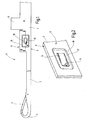
- FIG. 1 illustrates a knitting needle 1 which belongs to a knitting system and is part of it.
- the Knitting needle 1 has a shaft 2, which at one end to a shaft region 3 of lesser height passes, in turn end carries a hook 4. This can be required be associated with a pivotally mounted tongue 5.
- a suitable drive e.g. a castle, cooperates.
- the shaft 2 has, as shown in Figure 3, two preferably flat flanks 7, 8, extending from the needle top 9 (Figure 1) to the needle back 11th extend.
- a brake spring 15 is formed.
- This is at one suitable location of the shaft 2, for example in the Shank area 3 or at another location near the Foot 6 or directly below the same at least one Recess 16 is formed, which has a shallow depression with arched or preferably flat bottom forms.
- the recess 16 is surrounded by a closed edge 17, so they both axially forward and backward as well as to the needle top 9 and the needle back 11 is closed out.
- the Edge 17 is bounded by a surface area 18 of the flank 8, the one closed ring around the edge 17 around forms.
- the recess 16 forms a recess in the flank 8. This can be seen in particular from FIG.
- the in the area the recess remaining wall thickness W is clear less than the thickness to be measured between the flanks 7, 8 D of the shaft 2.
- a U-shaped section 19, e.g. from FIG 1 is visible, the brake spring 15 in the form of a Tongue 21 free.
- the thickness of the tongue 21 corresponds to the wall thickness W.
- the tongue 21 is slightly out of the plane of the flank. 7 bent out.
- the free end 22 of the tongue 21 can be outward arched or rounded.
- the cut 19 can, as illustrated, approximately rectangular his. Its width B is preferably greater than that Wall thickness W, so that the tongue 21 with a corresponding distance to the surrounding material of the bottom of the recess 16 free is placed. This can disturb the mobility of the Tongue 21 by abrasion, dirt or the like prevented become.
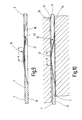
- the knitting needle 1 described so far can be in the needle channel 12 are used according to Figure 8.
- the width of the Channel 12 is so small that the tongue 21 and the Brake spring 15 resiliently supported on the side surface 13. Thereby is the knitting needle 1 against the opposite Side surface 14 pressed. It creates a friction, the one Longitudinal movement of the knitting needle 1 something inhibits. Due to the low Thickness of the tongue 21, this has a relatively high compliance and a big possible spring stroke.
- the to Forming the recess 16 and the tongue 15 required Area is relatively small. A significant weakening of the Shaft 2 is not available in terms of stability. If necessary, several such recesses 16 and tongues 15 are provided.
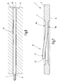
- FIG. 4 illustrates a modified embodiment The knitting needle 1. It is completely based on the above Description referenced. Unlike this one is the tongue 21 is not away from the recess 16 but through this bent through to the flank 8 out. The end is 22 rounded again.
- the planar and oriented substantially parallel to the flank 8 is an embodiment of a knitting needle 1 in Figure 5 illustrated in which the bottom 23 at an acute angle to the longitudinal direction of the knitting needle 1 and thus in one acute angle to the flanks 7, 8 is oriented.
- the tongue 21 tapers with respect to its wall thickness W from its beginning, i. from its root 24 towards its end 22. With this measure it becomes possible, a particularly yielding Design brake spring 15. Besides, she can be special small fail.
- the outline of the tongue 21 can, however, as in the embodiments described above rectangular his.
- FIG. 6 illustrates a corresponding exemplary embodiment one in their thickness according to Figure 3 or 4 constant or according to Figure 5 tapered tongue 21. This points e.g. a trapezoidal outline. Accordingly, the Section 19 formed approximately V-shaped.
- the tongue 21 can on its end 22 in an edge or in a rounding or leak a tip. By single or double rejuvenation the tongue 21 towards its end 22, a special good compliance of the tongue 21 can be achieved.
- Figure 7 illustrates a modification of the knitting needle 1 to the effect that in both flanks 7, 8 of the knitting needle.
- Recesses 16a, 16b are provided. These can, as illustrated, be the same size and the same depth and a constant depth according to the embodiments according to FIG. 3 or 4. For each recess 16a or 16b, however, is that these also one from the other Recess may have different size or shape. In particular can one or both recesses 16a, 16b accordingly Figure 5 may be wedge-shaped.
- the tongue is 21 either as illustrated, with a constant thickness or wedge-shaped with a taper towards its end 22 educated.
- Tongues 21 may be provided which are at the same flank 7 or 8 or bent to different flanks.
- the several tongues can be in a common recess or housed in separate recesses and rectangular, trapezoidal or triangular.
- FIG. 9 illustrates another modified embodiment the knitting needle 1. It is based on the same reference numbers completely to the above description directed. Unlike this one is the tongue 21 first of the recess 16 away beyond the edge 7 addition bent, and then at the highest point of the bend bent into the recess 16 so that her rounded End 22 is in the region of the recess 16.
- a knitting tool 1 is integral with one molded brake spring 15 is provided, which has a smaller thickness W has as the knitting tool 1. This allows the brake spring 15 a high compliance and a soft spring characteristic receive. This can be done with short spring lengths to reach. As a result, dimensional deviations of the spring have only small Influence on the spring force. The susceptibility to soiling is low. A corresponding knitting tool can be in a simple way.
Landscapes
- Engineering & Computer Science (AREA)
- Water Supply & Treatment (AREA)
- Textile Engineering (AREA)
- Organic Chemistry (AREA)
- Environmental & Geological Engineering (AREA)
- Chemical & Material Sciences (AREA)
- Life Sciences & Earth Sciences (AREA)
- Health & Medical Sciences (AREA)
- Public Health (AREA)
- Mechanical Engineering (AREA)
- General Engineering & Computer Science (AREA)
- Hydrology & Water Resources (AREA)
- Knitting Machines (AREA)
Abstract
Description
- Figur 1
- ein erfindungsgemäßes Systemteil in Form einer Maschinenstricknadel mit einstückig angeformter Bremsfeder in schematisierter Seitenansicht,
- Figur 2
- die Strickmaschinennadel nach Figur 1 in einer ausschnittsweisen perspektivischen Ansicht, in einem anderen Maßstab,
- Figur 3
- die Strickmaschinennadel nach Figur 1 und 2, geschnitten entlang der Linie III-III in Figur 1,
- Figur 4
- eine abgewandelte Ausführungsform der Nadel nach Figur 1, geschnitten entlang der Linie III-III,
- Figur 5
- die Strickmaschinennadel nach Figur 1, geschnitten entlang der Linie III-III in einer weiter abgewandelten Ausführungsform,
- Figur 6
- eine Strickmaschinennadel entsprechend der Strickmaschinennadel nach Figur 1 mit einer abgewandelten Zunge in einer ausschnittsweisen Seitenansicht,
- Figur 7
- eine abgewandelte Ausführungsform der Strickmaschinennadel entsprechend Figur 3 in einer Schnittdarstellung,
- Figur 8
- die Strickmaschinennadel in einem Nadelkanal in einer ausschnittsweisen Draufsicht,
- Figur 9
- eine abgewandelte Ausführungsform der Strickmaschinennadel in entspanntem Zustand in horizontal geschnittener, ausschnittsweiser Darstellung und
- Figur 10
- die Strickmaschinennadel nach Figur 9 in eingebautem Zustand in horizontal geschnittener, ausschnittsweiser Darstellung.
- 1
- Stricknadel
- 2
- Schaft
- 3
- Schaftbereich
- 4
- Haken
- 5
- Zunge
- 6
- Fuß
- 7, 8
- Flanken
- 9
- Nadeloberseite
- 11
- Nadelrücken
- 12
- Nadelkanal
- 13, 14
- Seitenflächen
- 15
- Bremsfeder
- 16, 16a, 16b
- Ausnehmungen
- 17
- Rand
- 18
- Flächenbereich
- 19
- Schnitt
- 21
- Zunge
- 22
- Ende
- 23
- Boden
- 24
- Wurzel
- A
- Bereich
- B
- Breite
- D
- Dicke
- W
- Wandstärke
Claims (14)
- Systemteil (1) eines Stricksystems einer maschenbildenden Maschine,
mit einem Schaft (2), der zwei zueinander im Wesentlichen parallele Flanken (7, 8) aufweist,
mit einer Ausnehmung (16), die in wenigstens einer der Flanken (7, 8) ausgebildet ist,
mit einer federnden Zunge (21), die an dem Schaft (2) in dem Bereich der Ausnehmung (16) ausgebildet und einstückig mit diesem verbunden ist und die über eine der beiden Flanken (7, 8) hinaussteht. - Systemteil nach Anspruch 1, dadurch gekennzeichnet, dass die Flanken (7, 8) ebene Flächen sind und voneinander einen Abstand aufweisen, der die Dicke (D) des Systemteils (1) bestimmt und dass die federnde Zunge (21) eine Dicke aufweist, die geringer ist als die Dicke (D) des Systemteils (1).
- Systemteil nach Anspruch 1, dadurch gekennzeichnet, dass die federnde Zunge (21) durch einen u-förmigen Schnitt (19) freigestellt ist.
- Systemteil nach Anspruch 3, dadurch gekennzeichnet, dass der Schnitt (19) eine Breite (B) aufweist, die zumindest so groß ist wie die Dicke (W) der Zunge (21).
- Systemteil nach Anspruch 1, dadurch gekennzeichnet, dass die Zunge (21) von der Ausnehmung (16) weg ausgebogen ist.
- Systemteil nach Anspruch 1, dadurch gekennzeichnet, dass die Zunge (21) in die Ausnehmung (16) hinein ausgebogen ist.
- Systemteil nach Anspruch 1, dadurch gekennzeichnet, dass die Zunge (21) eine konstante Dicke (W) aufweist.
- Systemteil nach Anspruch 1, dadurch gekennzeichnet, dass die Zunge (21) zu ihrem freien Ende (22) hin in ihrer Dicke (W) verjüngt ist.
- Systemteil nach Anspruch 1, dadurch gekennzeichnet, dass die Zunge (21) zu ihrem feien Ende (22) hin in ihrer Höhe verjüngt ist.
- Systemteil nach Anspruch 1, dadurch gekennzeichnet, dass die Zunge (21) ein abgerundetes Ende (22) aufweist.
- Systemteil nach Anspruch 1, dadurch gekennzeichnet, dass die Ausnehmung (16) eine konstante Tiefe aufweist.
- Systemteil nach Anspruch 1, dadurch gekennzeichnet, dass die Ausnehmung (16) eine zu dem freien Ende der Zunge (21) hin zunehmende Tiefe aufweist.
- Systemteil nach Anspruch 1, dadurch gekennzeichnet, dass die Ausnehmung einen geschlossenen Rand (17) aufweist.
- Systemteil nach Anspruch 1, dadurch gekennzeichnet, dass das Systemteil (1) eine Maschinenstricknadel ist.
Priority Applications (6)
| Application Number | Priority Date | Filing Date | Title |
|---|---|---|---|
| DE502004003833T DE502004003833D1 (de) | 2004-04-21 | 2004-04-21 | Systemteil mit Bremsfeder |
| EP04009397A EP1589136B1 (de) | 2004-04-21 | 2004-04-21 | Systemteil mit Bremsfeder |
| US11/108,847 US7117694B2 (en) | 2004-04-21 | 2005-04-19 | System component having a braking spring |
| JP2005123613A JP4124472B2 (ja) | 2004-04-21 | 2005-04-21 | 制動ばねを備えたシステム部 |
| KR1020050033136A KR100684493B1 (ko) | 2004-04-21 | 2005-04-21 | 브레이킹 스프링을 구비한 시스템 구성 요소 |
| CNB2005100676049A CN100436687C (zh) | 2004-04-21 | 2005-04-21 | 带有制动弹簧的系统组件 |
Applications Claiming Priority (1)
| Application Number | Priority Date | Filing Date | Title |
|---|---|---|---|
| EP04009397A EP1589136B1 (de) | 2004-04-21 | 2004-04-21 | Systemteil mit Bremsfeder |
Publications (2)
| Publication Number | Publication Date |
|---|---|
| EP1589136A1 true EP1589136A1 (de) | 2005-10-26 |
| EP1589136B1 EP1589136B1 (de) | 2007-05-16 |
Family
ID=34924672
Family Applications (1)
| Application Number | Title | Priority Date | Filing Date |
|---|---|---|---|
| EP04009397A Expired - Lifetime EP1589136B1 (de) | 2004-04-21 | 2004-04-21 | Systemteil mit Bremsfeder |
Country Status (6)
| Country | Link |
|---|---|
| US (1) | US7117694B2 (de) |
| EP (1) | EP1589136B1 (de) |
| JP (1) | JP4124472B2 (de) |
| KR (1) | KR100684493B1 (de) |
| CN (1) | CN100436687C (de) |
| DE (1) | DE502004003833D1 (de) |
Families Citing this family (32)
| Publication number | Priority date | Publication date | Assignee | Title |
|---|---|---|---|---|
| EP2045384B1 (de) * | 2007-10-02 | 2012-08-22 | Groz-Beckert KG | Wirknadel |
| US8393160B2 (en) | 2007-10-23 | 2013-03-12 | Flex Power Generation, Inc. | Managing leaks in a gas turbine system |
| US8671658B2 (en) | 2007-10-23 | 2014-03-18 | Ener-Core Power, Inc. | Oxidizing fuel |
| US8701413B2 (en) | 2008-12-08 | 2014-04-22 | Ener-Core Power, Inc. | Oxidizing fuel in multiple operating modes |
| US8621869B2 (en) | 2009-05-01 | 2014-01-07 | Ener-Core Power, Inc. | Heating a reaction chamber |
| EP2547888A4 (de) | 2010-03-15 | 2016-03-16 | Ener Core Power Inc | Verarbeitung von kraftstoff und wasser |
| DE102010056426B4 (de) * | 2010-12-28 | 2014-05-15 | H. Stoll Gmbh & Co. Kg | Strickmaschine |
| US9057028B2 (en) | 2011-05-25 | 2015-06-16 | Ener-Core Power, Inc. | Gasifier power plant and management of wastes |
| US9273606B2 (en) | 2011-11-04 | 2016-03-01 | Ener-Core Power, Inc. | Controls for multi-combustor turbine |
| US9279364B2 (en) | 2011-11-04 | 2016-03-08 | Ener-Core Power, Inc. | Multi-combustor turbine |
| US8980193B2 (en) | 2012-03-09 | 2015-03-17 | Ener-Core Power, Inc. | Gradual oxidation and multiple flow paths |
| US9359948B2 (en) | 2012-03-09 | 2016-06-07 | Ener-Core Power, Inc. | Gradual oxidation with heat control |
| US9328660B2 (en) | 2012-03-09 | 2016-05-03 | Ener-Core Power, Inc. | Gradual oxidation and multiple flow paths |
| US9353946B2 (en) | 2012-03-09 | 2016-05-31 | Ener-Core Power, Inc. | Gradual oxidation with heat transfer |
| US9267432B2 (en) | 2012-03-09 | 2016-02-23 | Ener-Core Power, Inc. | Staged gradual oxidation |
| US8980192B2 (en) | 2012-03-09 | 2015-03-17 | Ener-Core Power, Inc. | Gradual oxidation below flameout temperature |
| US9371993B2 (en) | 2012-03-09 | 2016-06-21 | Ener-Core Power, Inc. | Gradual oxidation below flameout temperature |
| US8671917B2 (en) | 2012-03-09 | 2014-03-18 | Ener-Core Power, Inc. | Gradual oxidation with reciprocating engine |
| US9567903B2 (en) | 2012-03-09 | 2017-02-14 | Ener-Core Power, Inc. | Gradual oxidation with heat transfer |
| US9534780B2 (en) | 2012-03-09 | 2017-01-03 | Ener-Core Power, Inc. | Hybrid gradual oxidation |
| US9381484B2 (en) | 2012-03-09 | 2016-07-05 | Ener-Core Power, Inc. | Gradual oxidation with adiabatic temperature above flameout temperature |
| US8807989B2 (en) | 2012-03-09 | 2014-08-19 | Ener-Core Power, Inc. | Staged gradual oxidation |
| US9359947B2 (en) | 2012-03-09 | 2016-06-07 | Ener-Core Power, Inc. | Gradual oxidation with heat control |
| US9273608B2 (en) | 2012-03-09 | 2016-03-01 | Ener-Core Power, Inc. | Gradual oxidation and autoignition temperature controls |
| US9347664B2 (en) | 2012-03-09 | 2016-05-24 | Ener-Core Power, Inc. | Gradual oxidation with heat control |
| US8844473B2 (en) | 2012-03-09 | 2014-09-30 | Ener-Core Power, Inc. | Gradual oxidation with reciprocating engine |
| US9726374B2 (en) | 2012-03-09 | 2017-08-08 | Ener-Core Power, Inc. | Gradual oxidation with flue gas |
| US9328916B2 (en) | 2012-03-09 | 2016-05-03 | Ener-Core Power, Inc. | Gradual oxidation with heat control |
| US9234660B2 (en) | 2012-03-09 | 2016-01-12 | Ener-Core Power, Inc. | Gradual oxidation with heat transfer |
| US9017618B2 (en) | 2012-03-09 | 2015-04-28 | Ener-Core Power, Inc. | Gradual oxidation with heat exchange media |
| US8926917B2 (en) | 2012-03-09 | 2015-01-06 | Ener-Core Power, Inc. | Gradual oxidation with adiabatic temperature above flameout temperature |
| US9206980B2 (en) | 2012-03-09 | 2015-12-08 | Ener-Core Power, Inc. | Gradual oxidation and autoignition temperature controls |
Citations (3)
| Publication number | Priority date | Publication date | Assignee | Title |
|---|---|---|---|---|
| DE2043566A1 (de) * | 1969-09-03 | 1971-04-08 | Kohorn, Alfred Oswald, New York, NY (VStA) | Nadel fur mit hoher Geschwindigkeit arbeitende Rundstrickmaschinen |
| DE2315836A1 (de) * | 1972-09-08 | 1974-03-14 | Alfred Oswald Kohorn | Strickmaschinennadel |
| EP1298238A1 (de) * | 2001-09-28 | 2003-04-02 | Groz-Beckert KG | Montage eines Auswahltelements an dem Körper eines Systemteils |
Family Cites Families (9)
| Publication number | Priority date | Publication date | Assignee | Title |
|---|---|---|---|---|
| US1178682A (en) * | 1914-08-31 | 1916-04-11 | Scott & Williams Inc | Knitting-machine needle. |
| US2004617A (en) * | 1934-05-12 | 1935-06-11 | Franklin Needle Company | Jack for knitting machine needles |
| US2024911A (en) * | 1935-09-04 | 1935-12-17 | Crawford Mfg Company | Jack for knitting machines |
| US2592787A (en) * | 1951-06-18 | 1952-04-15 | Herman A Blickle | Spring jack for knitting machine needles |
| US4089192A (en) * | 1976-04-30 | 1978-05-16 | Kohorn Alfred O | Knitting machine needles with improved cut-off and spring location |
| US4068500A (en) * | 1976-05-13 | 1978-01-17 | Kohorn Alfred O | Knitting machine needle with front and back cut-outs and spring |
| DE3336212C1 (de) | 1983-10-05 | 1985-01-03 | Theodor Groz & Söhne & Ernst Beckert Nadelfabrik KG, 7470 Albstadt | Gestanztes Strickwerkzeug fuer maschenbildende Textilmaschinen |
| DE3921506C1 (de) | 1989-06-30 | 1990-08-09 | Theodor Groz & Soehne & Ernst Beckert Nadelfabrik Kg, 7470 Albstadt, De | |
| DE10227533C1 (de) * | 2002-06-20 | 2003-12-11 | Groz Beckert Kg | Nadel mit Umhängefeder |
-
2004
- 2004-04-21 DE DE502004003833T patent/DE502004003833D1/de not_active Expired - Lifetime
- 2004-04-21 EP EP04009397A patent/EP1589136B1/de not_active Expired - Lifetime
-
2005
- 2005-04-19 US US11/108,847 patent/US7117694B2/en not_active Expired - Lifetime
- 2005-04-21 KR KR1020050033136A patent/KR100684493B1/ko not_active Expired - Fee Related
- 2005-04-21 CN CNB2005100676049A patent/CN100436687C/zh not_active Expired - Lifetime
- 2005-04-21 JP JP2005123613A patent/JP4124472B2/ja not_active Expired - Lifetime
Patent Citations (3)
| Publication number | Priority date | Publication date | Assignee | Title |
|---|---|---|---|---|
| DE2043566A1 (de) * | 1969-09-03 | 1971-04-08 | Kohorn, Alfred Oswald, New York, NY (VStA) | Nadel fur mit hoher Geschwindigkeit arbeitende Rundstrickmaschinen |
| DE2315836A1 (de) * | 1972-09-08 | 1974-03-14 | Alfred Oswald Kohorn | Strickmaschinennadel |
| EP1298238A1 (de) * | 2001-09-28 | 2003-04-02 | Groz-Beckert KG | Montage eines Auswahltelements an dem Körper eines Systemteils |
Also Published As
| Publication number | Publication date |
|---|---|
| EP1589136B1 (de) | 2007-05-16 |
| CN1690284A (zh) | 2005-11-02 |
| DE502004003833D1 (de) | 2007-06-28 |
| US7117694B2 (en) | 2006-10-10 |
| JP2005307425A (ja) | 2005-11-04 |
| US20050235700A1 (en) | 2005-10-27 |
| JP4124472B2 (ja) | 2008-07-23 |
| KR100684493B1 (ko) | 2007-02-22 |
| CN100436687C (zh) | 2008-11-26 |
| KR20060047344A (ko) | 2006-05-18 |
Similar Documents
| Publication | Publication Date | Title |
|---|---|---|
| EP1589136B1 (de) | Systemteil mit Bremsfeder | |
| EP2927360B1 (de) | Strickwerkzeug für Strickmaschinen | |
| EP0906980A1 (de) | Gestanztes Strickwerkzeug | |
| EP1988198A1 (de) | Werkzeugsatz und Barre für eine Wirkmaschine | |
| DE10333172B4 (de) | Strickmaschinennadel | |
| DE102006004099B3 (de) | Wirkelement, insbesondere Wirknadel einer Kettenwirkmaschine, sowie Wirkmaschinen-Barre | |
| EP0290805B1 (de) | Gestanztes Strickwerkzeug für Textilmaschinen, insb. Strick-und Wirkmaschinen | |
| EP2088228B1 (de) | Zungennadel | |
| DE19720169C2 (de) | Auswahlplatine | |
| EP0143890B1 (de) | Gestanztes Strickwerkzeug für maschenbildende Textilmaschinen | |
| EP0282647A1 (de) | Gestanztes Strickwerkzeug für Textilmaschinen, insbesondere Strick- oder Wirkmaschinen | |
| EP0402587B1 (de) | Strickwerkzeug für Strickmaschinen | |
| EP0375843B1 (de) | Gestanztes Strickwerkzeug für Textilmaschinen, insbesondere Strick- und Wirkmaschinen | |
| EP0426994B1 (de) | Gestanztes Strickwerkzeug für Textilmaschinen | |
| EP2224048B1 (de) | Zungennadel mit drehendem Achsstift | |
| EP1801276B1 (de) | Systemteil für ein Stricksystem | |
| EP1731651B1 (de) | Zungennadel für Textilmaschinen | |
| EP0735174B1 (de) | Zungennadel für Maschinen zur Herstellung von Maschenware | |
| DE102010017950B4 (de) | Auswahlplatine | |
| DD289068A5 (de) | Wirkwerkzeughalterung, insbesondere fuer schiebernadeln, an kettenwirkmaschinen, speziell naehwirkmaschinen | |
| EP1303659A1 (de) | Zungennadel mit abgesetztem zungenschaft | |
| EP1303658B1 (de) | Zungennadel mit abgesetztem zungenschlitz | |
| EP4187006B1 (de) | Strickwerkzeug und verfahren zur herstellung eines strickwerkzeugs | |
| EP0890668A2 (de) | Gestanztes Strickwerkzeug für Textilmaschinen, insbesondere Strick- und Wirkmaschinen | |
| EP2196571B1 (de) | Zungennadel mit Gleitfläche |
Legal Events
| Date | Code | Title | Description |
|---|---|---|---|
| PUAI | Public reference made under article 153(3) epc to a published international application that has entered the european phase |
Free format text: ORIGINAL CODE: 0009012 |
|
| 17P | Request for examination filed |
Effective date: 20040421 |
|
| AK | Designated contracting states |
Kind code of ref document: A1 Designated state(s): AT BE BG CH CY CZ DE DK EE ES FI FR GB GR HU IE IT LI LU MC NL PL PT RO SE SI SK TR |
|
| AX | Request for extension of the european patent |
Extension state: AL HR LT LV MK |
|
| GRAP | Despatch of communication of intention to grant a patent |
Free format text: ORIGINAL CODE: EPIDOSNIGR1 |
|
| AKX | Designation fees paid |
Designated state(s): DE FR GB IT TR |
|
| GRAS | Grant fee paid |
Free format text: ORIGINAL CODE: EPIDOSNIGR3 |
|
| GRAA | (expected) grant |
Free format text: ORIGINAL CODE: 0009210 |
|
| AK | Designated contracting states |
Kind code of ref document: B1 Designated state(s): DE FR GB IT TR |
|
| REG | Reference to a national code |
Ref country code: GB Ref legal event code: FG4D Free format text: NOT ENGLISH |
|
| GBT | Gb: translation of ep patent filed (gb section 77(6)(a)/1977) |
Effective date: 20070516 |
|
| REF | Corresponds to: |
Ref document number: 502004003833 Country of ref document: DE Date of ref document: 20070628 Kind code of ref document: P |
|
| PLBE | No opposition filed within time limit |
Free format text: ORIGINAL CODE: 0009261 |
|
| STAA | Information on the status of an ep patent application or granted ep patent |
Free format text: STATUS: NO OPPOSITION FILED WITHIN TIME LIMIT |
|
| 26N | No opposition filed |
Effective date: 20080219 |
|
| PGFP | Annual fee paid to national office [announced via postgrant information from national office to epo] |
Ref country code: GB Payment date: 20120419 Year of fee payment: 9 Ref country code: FR Payment date: 20120507 Year of fee payment: 9 |
|
| GBPC | Gb: european patent ceased through non-payment of renewal fee |
Effective date: 20130421 |
|
| PG25 | Lapsed in a contracting state [announced via postgrant information from national office to epo] |
Ref country code: GB Free format text: LAPSE BECAUSE OF NON-PAYMENT OF DUE FEES Effective date: 20130421 |
|
| REG | Reference to a national code |
Ref country code: FR Ref legal event code: ST Effective date: 20131231 |
|
| PG25 | Lapsed in a contracting state [announced via postgrant information from national office to epo] |
Ref country code: FR Free format text: LAPSE BECAUSE OF NON-PAYMENT OF DUE FEES Effective date: 20130430 |
|
| PGFP | Annual fee paid to national office [announced via postgrant information from national office to epo] |
Ref country code: IT Payment date: 20230310 Year of fee payment: 20 |
|
| PGFP | Annual fee paid to national office [announced via postgrant information from national office to epo] |
Ref country code: DE Payment date: 20230430 Year of fee payment: 20 |
|
| PGFP | Annual fee paid to national office [announced via postgrant information from national office to epo] |
Ref country code: TR Payment date: 20230418 Year of fee payment: 20 |
|
| REG | Reference to a national code |
Ref country code: DE Ref legal event code: R071 Ref document number: 502004003833 Country of ref document: DE |