EP1587973B1 - Fasertransport und -ablegevorrichtung zum anschluss an eine karde - Google Patents
Fasertransport und -ablegevorrichtung zum anschluss an eine karde Download PDFInfo
- Publication number
- EP1587973B1 EP1587973B1 EP03776810A EP03776810A EP1587973B1 EP 1587973 B1 EP1587973 B1 EP 1587973B1 EP 03776810 A EP03776810 A EP 03776810A EP 03776810 A EP03776810 A EP 03776810A EP 1587973 B1 EP1587973 B1 EP 1587973B1
- Authority
- EP
- European Patent Office
- Prior art keywords
- fibre
- arm
- depositing device
- conveying
- deflection means
- Prior art date
- Legal status (The legal status is an assumption and is not a legal conclusion. Google has not performed a legal analysis and makes no representation as to the accuracy of the status listed.)
- Expired - Lifetime
Links
- 239000000835 fiber Substances 0.000 title claims description 32
- 238000013016 damping Methods 0.000 claims description 15
- 238000000151 deposition Methods 0.000 claims description 13
- 238000009960 carding Methods 0.000 claims description 7
- 238000006073 displacement reaction Methods 0.000 claims description 6
- 230000001105 regulatory effect Effects 0.000 claims description 4
- 230000000750 progressive effect Effects 0.000 claims description 3
- OKTJSMMVPCPJKN-UHFFFAOYSA-N Carbon Chemical compound [C] OKTJSMMVPCPJKN-UHFFFAOYSA-N 0.000 claims 1
- 229910052799 carbon Inorganic materials 0.000 claims 1
- 238000013459 approach Methods 0.000 description 4
- 230000008859 change Effects 0.000 description 4
- 238000005516 engineering process Methods 0.000 description 4
- 238000007665 sagging Methods 0.000 description 4
- 238000001514 detection method Methods 0.000 description 3
- 230000033001 locomotion Effects 0.000 description 3
- 230000004044 response Effects 0.000 description 3
- 229920000049 Carbon (fiber) Polymers 0.000 description 2
- 101100390736 Danio rerio fign gene Proteins 0.000 description 2
- 101100390738 Mus musculus Fign gene Proteins 0.000 description 2
- 230000008901 benefit Effects 0.000 description 2
- 230000001914 calming effect Effects 0.000 description 2
- 239000004917 carbon fiber Substances 0.000 description 2
- 238000010276 construction Methods 0.000 description 2
- 238000012423 maintenance Methods 0.000 description 2
- VNWKTOKETHGBQD-UHFFFAOYSA-N methane Chemical compound C VNWKTOKETHGBQD-UHFFFAOYSA-N 0.000 description 2
- 230000009467 reduction Effects 0.000 description 2
- 238000009420 retrofitting Methods 0.000 description 2
- 238000004904 shortening Methods 0.000 description 2
- 241000123589 Dipsacus Species 0.000 description 1
- 230000006978 adaptation Effects 0.000 description 1
- 230000000694 effects Effects 0.000 description 1
- 239000000446 fuel Substances 0.000 description 1
- 239000000463 material Substances 0.000 description 1
- 230000007246 mechanism Effects 0.000 description 1
- 238000000034 method Methods 0.000 description 1
- 230000010355 oscillation Effects 0.000 description 1
- 230000008569 process Effects 0.000 description 1
- 230000001953 sensory effect Effects 0.000 description 1
- 238000011144 upstream manufacturing Methods 0.000 description 1
Images

Classifications
-
- D—TEXTILES; PAPER
- D01—NATURAL OR MAN-MADE THREADS OR FIBRES; SPINNING
- D01G—PRELIMINARY TREATMENT OF FIBRES, e.g. FOR SPINNING
- D01G23/00—Feeding fibres to machines; Conveying fibres between machines
- D01G23/06—Arrangements in which a machine or apparatus is regulated in response to changes in the volume or weight of fibres fed, e.g. piano motions
Definitions
- the invention relates to a fiber transport and -ablegevoriques according to the preamble of patent claim 1
- US 5,774,940 discloses a device in which, for a given carding speed, a regulation of both the roller pairs of the drafting system takes place, as well as a separate control of Kannenstockantriebs. Between the Regulierstrecktechnik and the Kannenstock the sliver is guided as a freely sagging loop. A level sensor detects the height of this loop, from this signal is derived via a process computer, a speed adjustment for one hand Regulierstrecktechnik and on the other hand, the depositing speed of the can can.
- a device in which the fiber is deflected to compensate for the sliver length.
- a tube having two sections, which is rotatably mounted about the axis of the first, horizontal portion, wherein the second portion is angled relative to the first.
- the sliver When leaving this second section, the sliver is deflected in the form of a loop, and then passes over another bend to the can-stock. If the tape is lightly loaded, the tube assumes its lowered position.
- the angled portion of the tube is raised in accordance with the fiber shortening, the resulting angle of rotation of the first tube portion is detected, and the fiber speed is adjusted.
- the tension exerted by the tube on the fiber depends on the angle of rotation of the tube. However, this tension can have an influence on the strip quality of the fiber.
- the invention has for its object to provide a working with simple control means fiber transport and -ablegevoriques for connection to a card, which allows the adjustment and the compensation of the belt speed without affecting the tape quality behind the drafting system output.
- the control is based on a local displacement of deflecting means for the sliver, wherein these deflecting means. consist of an arm pivotable about a pivot axis, at the free end of a roller can be freely rotatably supported, over which the sliver is guided and deflected. Therefore, the sliver does not run directly from the last pair of rollers of the drafting to the can stock, but it takes the "detour" on the displaceable deflection.
- discrete signal transmitters are provided for a first and for a second end position of the deflection means. It is therefore not the size of the local displacement of the deflection over the entire possible range of motion, but only discrete end positions or an approximation to such end positions are detected.
- means are provided for changing the drive speed of the can stack in the case of a signal output by one of the signal transmitters and in dependence on the time interval which has elapsed since the last signal output. Only when one of the end positions is reached, is an adaptation of the basic ratio by intervention in the operating speed of the can-can stock. The longer the time span between the successive reaching of two end positions, the lower the speed adjustment of the can cane.
- each two signal transmitters are arranged slightly offset from one another. In this way, an approach to the end position can already be detected by signal technology, and accordingly the control can be refined.
- Proximity switches are preferably used as signal transmitters.
- the pivoting arm a particularly lightweight and thus almost inertia-free construction is proposed, in which the arm consists of a thin-walled tube.
- a tube made of carbon fiber which combines the advantage of low weight with high strength and extensive freedom from vibration.
- Such an arm works with very low moments of inertia and therefore a good response to any elongation or reduction of the deflected over the arm Faserbahdes.
- the pivot axis is arranged for the arm on the can stock, and the sliver is guided vertically between the other role and the can stock, so that the sliver passes on the shortest path and from above vertically down into the can stock.
- an embodiment of the invention is characterized in that the deflection means with a in the direction of displacement acting damping element are provided with progressive damping characteristic, so that unfavorable vibrations are largely avoided for the regulation of Kannenstocks.
- the damping element is arranged in such a way that this acts damping on the pivot axis of the pivotable arm.
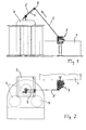
- the Fign. 1 and 2 show an overall illustration of a carding machine 1, which is shown only partially here, and which is followed by a drafting unit 2 in relation to the strip running direction, to which in turn a can can 3 is connected downstream.
- a pot is turned off in a conventional manner, in which the sliver is stored in controlled loops.
- the can stock 3 is provided with a can changer, which offers space for a total of three sliver cans 4.
- the sliver is provided with the reference numeral 5.
- a controlled stretching of the sliver coming from the carding 1 takes place, so as to improve the structure and in particular the uniformity of the sliver.
- Such drafting systems are known, for. B. from the Swiss patent CH 692 349.
- a drafting system often consists of several pairs of rollers, wherein at least the last pair of rollers with a higher, individually adjustable speed is driven. This speed difference causes the stretching and equalization of the sliver.
- the drafting system 2 is therefore designed as Regulierstreckwerk and this has a main drive and a separate, fast-reacting regulating drive.
- the main drive has a fixed, but in size programmable translation to the card 1.
- the Regulierantrieb has a fixed, but in its size but also programmable basic translation for driving the can stack 3.
- the last pair of rollers or possibly the last pairs of rollers of the drafting system 2 which are often referred to as drafting system exit rollers, can accelerate or retard in the short term by the fast-reacting Regulierantrieb compared to the basic translation.
- a fast-acting servo drive z. B. can be the output rollers with a frequency in the millisecond range up to 25% change in their speed.
- Such a rapid change in speed can not follow the drafting unit 2 downstream can Stock 3, since its mechanical drive components react too slow. As a result, there are almost permanent differences in speed.
- the arm 7 is kept under constant counter pressure, so that the sliver 5 remains evenly stretched on its way from the drafting to the can cane. This tension is so low that the structure of the sliver, as this leaves the drafting system 2, is no longer affected.
- a short stand 11 On the top of the can stock a short stand 11 is fixed, which carries at its upper end the bearing for the pivot axis 6 of the arm 7.
- the arm 7 is therefore pivotable about the axis 6, wherein damping elements 16 in the region of the pivot axis 6 exert a progressive damping effect on the rotational movement of the arm, d. H. the greater the speed of rotation of the arm 7, the greater the damping.
- the long lever of the arm 7 consists of a tube 9, at the free end of which the already described roller 8 is freely rotatably mounted.
- the tube 9 is made of a very light, but low-vibration and high-strength material such. B. carbon fiber.
- the short lever of the arm 7 is formed by the weight member 10.
- the weight element 10 sits as close as possible to the pivot axis 6 of the arm so as to bring the mass inertia forces close to the pivot center.
- the weight element 10 is screwed via an adjusting thread 12 with lock nut 13 in the arm 7, wherein by adjusting this thread, the leverage of the weight element can be adjusted.
- the counterweight for the long arm 7 and the roller 8 serving weight element 10 is so dimensioned and balanced that the arranged at the free end of the tube 9 roller 8 always exerts a certain tension on the guided over this roller 8 sliver 5. It is advantageous if the sliver 5, as shown in FIG. 3 reveals, is guided in the middle position of the arm 7 in a deflection angle of about 90 ° on the roller 8.
- Fig. 4 reveals in another view that the deflection means for the sliver except the displaceable roller 8 still another role 14 belongs.
- the further roller 14 is freely rotatably mounted on the pivot axis 6 of the arm 7. Furthermore, the roller 14 is arranged so that the fiber sliver guided over it 5 then passes vertically into the arranged below Kannenstock 3.
- the pivoting movement of the roller bearing arm 7 is limited by two end positions, which are each detectable.
- a first signal transmitter 15a for the first end position of the arm, and a second signal transmitter 15b for the second end position of the arm is integrated into the pivot joint.
- Intermediate layers of the arm 7, however, are not sensory detected, but rather a signal is released only when the arm 7 approaches one of its two end positions at least.
- Fig. 6 also shows a damping element 16, which operates progressively and exerts a higher damping force on the pivot axis 6 of the arm, the greater the displacement speed of the arm. This damping leads to a calming of the arm with respect to short-wave oscillation amplitudes.
- the band tension of the guided over sliver 5 is kept constant, also short and long-wave translation changes are well balanced.
- the detection signals of the limit switches 15a, 15b are sent to a central control unit, which calculates therefrom a speed change for the basic setting of the can stack 3.
- Approaches z As the arm 7 with its role 8 of the lower end position, which is equivalent to a reduction of the sliver length between drafting and caning, a slowing down of the basic speed of the can stack 3 is calculated by the central control unit. Conversely, the arm 7 increases with its role 8, which is equivalent to an elongation of the sliver section between drafting and Kannenstock, the basic speed of the can stack is increased, and thus the driving speed of the can can.
- the central control unit is connected to a controller, which gives appropriate drive commands, so as to make an adjustment and thus Einjust suits the basic translation of Regulierstreckwerks to can-can. Furthermore, the time interval which has elapsed since the last signal output by the signal transmitters 15a, 15b enters the control loop. The larger this time interval, the lower the adjustments made by the central control unit to the speed of the fuel can drive. This consideration of time data leads to a significant calming of the control behavior, and in this way automatically the optimal basic translation is found.
Landscapes
- Engineering & Computer Science (AREA)
- Textile Engineering (AREA)
- Preliminary Treatment Of Fibers (AREA)
- Spinning Or Twisting Of Yarns (AREA)
- Coiling Of Filamentary Materials In General (AREA)
Applications Claiming Priority (3)
| Application Number | Priority Date | Filing Date | Title |
|---|---|---|---|
| DE10252181A DE10252181B3 (de) | 2002-11-09 | 2002-11-09 | Fasertransport und -ablegevorrichtung zum Anschluß an eine Karde |
| DE10252181 | 2002-11-09 | ||
| PCT/DE2003/003508 WO2004044291A1 (de) | 2002-11-09 | 2003-10-22 | Fasertransport und -ablegevorrichtung zum anschluss an eine karde |
Publications (2)
| Publication Number | Publication Date |
|---|---|
| EP1587973A1 EP1587973A1 (de) | 2005-10-26 |
| EP1587973B1 true EP1587973B1 (de) | 2007-01-24 |
Family
ID=32308505
Family Applications (1)
| Application Number | Title | Priority Date | Filing Date |
|---|---|---|---|
| EP03776810A Expired - Lifetime EP1587973B1 (de) | 2002-11-09 | 2003-10-22 | Fasertransport und -ablegevorrichtung zum anschluss an eine karde |
Country Status (6)
| Country | Link |
|---|---|
| US (1) | US7318254B2 (zh) |
| EP (1) | EP1587973B1 (zh) |
| CN (1) | CN100410432C (zh) |
| AU (1) | AU2003286103A1 (zh) |
| DE (2) | DE10252181B3 (zh) |
| WO (1) | WO2004044291A1 (zh) |
Families Citing this family (6)
| Publication number | Priority date | Publication date | Assignee | Title |
|---|---|---|---|---|
| CN103588006A (zh) * | 2013-11-14 | 2014-02-19 | 际华三五三七制鞋有限责任公司 | 自动调整胶鞋围条裁断点位置的方法及装置 |
| CN103723549A (zh) * | 2013-12-27 | 2014-04-16 | 绍兴科泰斯纺织品检验有限公司 | 验布机的张力调节装置 |
| DE102015113044A1 (de) * | 2015-08-07 | 2017-02-09 | TRüTZSCHLER GMBH & CO. KG | Vorrichtung zum Füllen einer Kanne mit Faserband |
| CN107089555A (zh) * | 2017-06-14 | 2017-08-25 | 深圳市铁工机自动化技术有限公司 | 一种用于塑料导爆管的环绕式集线桶 |
| DE102017124562A1 (de) * | 2017-10-20 | 2019-04-25 | Maschinenfabrik Rieter Ag | Textilmaschinenverbund mit einer Bandspeichereinheit zum Zwischenspeichern von Faserband |
| JP7019278B1 (ja) * | 2021-09-03 | 2022-02-15 | 旭精機工業株式会社 | 巻回装置及び巻回体の製造方法 |
Family Cites Families (15)
| Publication number | Priority date | Publication date | Assignee | Title |
|---|---|---|---|---|
| US2897550A (en) * | 1956-09-27 | 1959-08-04 | Southern States Equipment Corp | Sliver guide for textile coiler |
| GB1436029A (en) * | 1973-10-04 | 1976-05-19 | Texctronol | Electromechanical system for controlling the speed of a coiler at the output of a textile carding machine |
| US3938222A (en) * | 1974-10-07 | 1976-02-17 | John D. Hollingsworth On Wheels, Inc. | Tracking guide for planetary coiler |
| DE2543839B1 (de) * | 1975-10-01 | 1976-11-25 | Graf & Co Ag | Vorrichtung zum erzeugen eines gleichmaessigen textilen faserbandes |
| CH627498A5 (de) * | 1978-04-26 | 1982-01-15 | Zellweger Uster Ag | Verfahren und vorrichtung zur ausregulierung von bandgewichtsschwankungen an karden, krempeln und strecken. |
| DE3523660A1 (de) * | 1985-06-28 | 1987-01-08 | Basf Ag | Vorrichtung fuer die herstellung eines hohlkoerpers aus verbundmaterial |
| DE3837596A1 (de) * | 1988-11-05 | 1990-05-10 | Rosink Gmbh & Co Kg | Kannenstock |
| GB2255353B (en) * | 1991-05-01 | 1994-11-30 | Hollingsworth On Wheels John D | Drive between an autoleveller and a coiler |
| IT1276944B1 (it) * | 1995-10-16 | 1997-11-03 | Marzoli & C Spa | Dispositivo di regolazione e di controllo della tensione del nastro ceduto dal gruppo di stiro di una carda al gruppo di raccolta del |
| IT1292144B1 (it) * | 1996-06-29 | 1999-01-25 | Truetzschler & Co | Dispositivo su una carda,in cui all'uscita della carda e' previsto un imbuto del velo con cilindri di estrazione |
| US5774940A (en) * | 1996-07-19 | 1998-07-07 | North Carolina State University | Draftless sliver coiler packaging system for automated textile drafting system |
| IT1293614B1 (it) * | 1996-08-22 | 1999-03-08 | Truetzschler & Co | Dispositivo per il trasporto e l'approntamento di vasi,in particolare fra due stiratoi consecutivi nel ciclo di lavorazione |
| DE19811497A1 (de) * | 1998-03-17 | 1999-09-23 | Rieter Ingolstadt Spinnerei | Verfahren und Vorrichtung zum Speichern eines textilen Fasermaterials zwischen Arbeitsorganen von Spinnereimaschinen |
| US6199411B1 (en) * | 1999-03-01 | 2001-03-13 | Sara Lee Corporation | Dyeing range unloader |
| DE10052478A1 (de) * | 2000-10-23 | 2002-05-02 | Bayer Faser Gmbh | Verfahren zur Ablage von Elastanfäden mit groben Titern |
-
2002
- 2002-11-09 DE DE10252181A patent/DE10252181B3/de not_active Expired - Fee Related
-
2003
- 2003-10-22 CN CNB2003801029295A patent/CN100410432C/zh not_active Expired - Fee Related
- 2003-10-22 WO PCT/DE2003/003508 patent/WO2004044291A1/de active IP Right Grant
- 2003-10-22 US US10/533,792 patent/US7318254B2/en not_active Expired - Fee Related
- 2003-10-22 AU AU2003286103A patent/AU2003286103A1/en not_active Abandoned
- 2003-10-22 EP EP03776810A patent/EP1587973B1/de not_active Expired - Lifetime
- 2003-10-22 DE DE50306414T patent/DE50306414D1/de not_active Expired - Lifetime
Also Published As
| Publication number | Publication date |
|---|---|
| WO2004044291B1 (de) | 2004-07-15 |
| EP1587973A1 (de) | 2005-10-26 |
| DE50306414D1 (de) | 2007-03-15 |
| CN100410432C (zh) | 2008-08-13 |
| CN1711377A (zh) | 2005-12-21 |
| WO2004044291A1 (de) | 2004-05-27 |
| AU2003286103A1 (en) | 2004-06-03 |
| US20060196012A1 (en) | 2006-09-07 |
| DE10252181B3 (de) | 2004-10-07 |
| US7318254B2 (en) | 2008-01-15 |
Similar Documents
| Publication | Publication Date | Title |
|---|---|---|
| EP0914287B1 (de) | Verfahren zum aufspulen eines anlaufenden fadens | |
| EP0365931B1 (de) | Verfahren und Vorrichtung zum Einstellen einer Luftspinnvorrichtung | |
| EP0280038B1 (de) | Kalander | |
| EP0165511B1 (de) | Vorrichtung zum Aufwinden eines mit konstanter Geschwindigkeit zugeführten Fadens auf eine Kreuzspule | |
| AT398988B (de) | Spannungseinstellvorrichtung für ein elastisches band | |
| DE2513981A1 (de) | Verfahren und vorrichtung zum steuern und/oder regeln der fadenspannung beim wickeln einer textilspule | |
| EP0312774B1 (de) | Kannenstock an Karde mit elektronischer Antriebsvorrichtung | |
| EP0650406B1 (de) | Vorrichtung zum formschneiden vorlaufender werkstoffbahnen | |
| EP1587973B1 (de) | Fasertransport und -ablegevorrichtung zum anschluss an eine karde | |
| EP0790084B1 (de) | Haspelanlage für Bänder | |
| EP1781847B1 (de) | Vorrichtung und verfahren an einer karde | |
| CH681156A5 (zh) | ||
| EP0593951B1 (de) | Spinnereivorrichtung | |
| DE2059283A1 (de) | Bandfuehrungs- und -dehnvorrichtung | |
| DE3723433C2 (de) | Bandwebmaschine | |
| DE3212176A1 (de) | Bahnfuehrungsvorrichtung | |
| EP0012937B1 (de) | Changiervorrichtung an Aufwickelvorrichtungen für Fäden mit veränderbarem Fadenführerhub und stufenloser, kollektiver Verstellbarkeit des Flankenwinkels der Spulen | |
| EP0031843B1 (de) | Flyerflügel | |
| DE3023068C2 (de) | Vorrichtung zum geregelten Zuführung und zum Abziehen eines Fadens in eine bzw. aus einer Fadenbehandlungsstrecke | |
| DE2939693C2 (de) | Vliesabnahmevorrichtung | |
| EP1947042B1 (de) | Wickeleinrichtung | |
| DE2163161C3 (de) | Fadenverbinder für eine längs der Spindelreihen einer Spinnmaschine od.dgl. verfahrbare Wartungsvorrichtung | |
| EP0334016B1 (de) | Vorrichtung zum Bewegen eines Falzschwertes einer Falzmaschine | |
| DE4300686A1 (de) | Vorrichtung zum Auseinanderwickeln und getrennten Aufwickeln von gegebenenfalls längsgeschnittenen mehrlagigen Folienbahnen, insbesondere Aluminiumfolien und dünne Aluminiumbänder | |
| EP0885668A2 (de) | Vorrichtung zur Bildung von Schlingen aus einem aus einer Walzdrahtstrasse austretenden Drahtstrang mittels eines rotierenden Schlingenlegers |
Legal Events
| Date | Code | Title | Description |
|---|---|---|---|
| PUAI | Public reference made under article 153(3) epc to a published international application that has entered the european phase |
Free format text: ORIGINAL CODE: 0009012 |
|
| 17P | Request for examination filed |
Effective date: 20050226 |
|
| AK | Designated contracting states |
Kind code of ref document: A1 Designated state(s): AT BE BG CH CY CZ DE DK EE ES FI FR GB GR HU IE IT LI LU MC NL PT RO SE SI SK TR |
|
| AX | Request for extension of the european patent |
Extension state: AL LT LV MK |
|
| DAX | Request for extension of the european patent (deleted) | ||
| RBV | Designated contracting states (corrected) |
Designated state(s): CH DE IT LI |
|
| GRAP | Despatch of communication of intention to grant a patent |
Free format text: ORIGINAL CODE: EPIDOSNIGR1 |
|
| GRAS | Grant fee paid |
Free format text: ORIGINAL CODE: EPIDOSNIGR3 |
|
| GRAA | (expected) grant |
Free format text: ORIGINAL CODE: 0009210 |
|
| AK | Designated contracting states |
Kind code of ref document: B1 Designated state(s): CH DE IT LI |
|
| REG | Reference to a national code |
Ref country code: CH Ref legal event code: EP |
|
| REF | Corresponds to: |
Ref document number: 50306414 Country of ref document: DE Date of ref document: 20070315 Kind code of ref document: P |
|
| PLBE | No opposition filed within time limit |
Free format text: ORIGINAL CODE: 0009261 |
|
| STAA | Information on the status of an ep patent application or granted ep patent |
Free format text: STATUS: NO OPPOSITION FILED WITHIN TIME LIMIT |
|
| 26N | No opposition filed |
Effective date: 20071025 |
|
| PGFP | Annual fee paid to national office [announced via postgrant information from national office to epo] |
Ref country code: CH Payment date: 20101025 Year of fee payment: 8 Ref country code: DE Payment date: 20101103 Year of fee payment: 8 |
|
| PGFP | Annual fee paid to national office [announced via postgrant information from national office to epo] |
Ref country code: IT Payment date: 20101027 Year of fee payment: 8 |
|
| REG | Reference to a national code |
Ref country code: CH Ref legal event code: PL |
|
| PG25 | Lapsed in a contracting state [announced via postgrant information from national office to epo] |
Ref country code: DE Free format text: LAPSE BECAUSE OF NON-PAYMENT OF DUE FEES Effective date: 20120501 Ref country code: LI Free format text: LAPSE BECAUSE OF NON-PAYMENT OF DUE FEES Effective date: 20111031 Ref country code: CH Free format text: LAPSE BECAUSE OF NON-PAYMENT OF DUE FEES Effective date: 20111031 |
|
| REG | Reference to a national code |
Ref country code: DE Ref legal event code: R119 Ref document number: 50306414 Country of ref document: DE Effective date: 20120501 |
|
| PG25 | Lapsed in a contracting state [announced via postgrant information from national office to epo] |
Ref country code: IT Free format text: LAPSE BECAUSE OF NON-PAYMENT OF DUE FEES Effective date: 20111022 |