EP1587973B1 - Fiber conveying and discarding device to be connected to a carder - Google Patents
Fiber conveying and discarding device to be connected to a carder Download PDFInfo
- Publication number
- EP1587973B1 EP1587973B1 EP03776810A EP03776810A EP1587973B1 EP 1587973 B1 EP1587973 B1 EP 1587973B1 EP 03776810 A EP03776810 A EP 03776810A EP 03776810 A EP03776810 A EP 03776810A EP 1587973 B1 EP1587973 B1 EP 1587973B1
- Authority
- EP
- European Patent Office
- Prior art keywords
- fibre
- arm
- depositing device
- conveying
- deflection means
- Prior art date
- Legal status (The legal status is an assumption and is not a legal conclusion. Google has not performed a legal analysis and makes no representation as to the accuracy of the status listed.)
- Expired - Lifetime
Links
- 239000000835 fiber Substances 0.000 title claims description 32
- 238000013016 damping Methods 0.000 claims description 15
- 238000000151 deposition Methods 0.000 claims description 13
- 238000009960 carding Methods 0.000 claims description 7
- 238000006073 displacement reaction Methods 0.000 claims description 6
- 230000001105 regulatory effect Effects 0.000 claims description 4
- 230000000750 progressive effect Effects 0.000 claims description 3
- OKTJSMMVPCPJKN-UHFFFAOYSA-N Carbon Chemical compound [C] OKTJSMMVPCPJKN-UHFFFAOYSA-N 0.000 claims 1
- 229910052799 carbon Inorganic materials 0.000 claims 1
- 238000013459 approach Methods 0.000 description 4
- 230000008859 change Effects 0.000 description 4
- 238000005516 engineering process Methods 0.000 description 4
- 238000007665 sagging Methods 0.000 description 4
- 238000001514 detection method Methods 0.000 description 3
- 230000033001 locomotion Effects 0.000 description 3
- 230000004044 response Effects 0.000 description 3
- 229920000049 Carbon (fiber) Polymers 0.000 description 2
- 101100390736 Danio rerio fign gene Proteins 0.000 description 2
- 101100390738 Mus musculus Fign gene Proteins 0.000 description 2
- 230000008901 benefit Effects 0.000 description 2
- 230000001914 calming effect Effects 0.000 description 2
- 239000004917 carbon fiber Substances 0.000 description 2
- 238000010276 construction Methods 0.000 description 2
- 238000012423 maintenance Methods 0.000 description 2
- VNWKTOKETHGBQD-UHFFFAOYSA-N methane Chemical compound C VNWKTOKETHGBQD-UHFFFAOYSA-N 0.000 description 2
- 230000009467 reduction Effects 0.000 description 2
- 238000009420 retrofitting Methods 0.000 description 2
- 238000004904 shortening Methods 0.000 description 2
- 241000123589 Dipsacus Species 0.000 description 1
- 230000006978 adaptation Effects 0.000 description 1
- 230000000694 effects Effects 0.000 description 1
- 239000000446 fuel Substances 0.000 description 1
- 239000000463 material Substances 0.000 description 1
- 230000007246 mechanism Effects 0.000 description 1
- 238000000034 method Methods 0.000 description 1
- 230000010355 oscillation Effects 0.000 description 1
- 230000008569 process Effects 0.000 description 1
- 230000001953 sensory effect Effects 0.000 description 1
- 238000011144 upstream manufacturing Methods 0.000 description 1
Images

Classifications
-
- D—TEXTILES; PAPER
- D01—NATURAL OR MAN-MADE THREADS OR FIBRES; SPINNING
- D01G—PRELIMINARY TREATMENT OF FIBRES, e.g. FOR SPINNING
- D01G23/00—Feeding fibres to machines; Conveying fibres between machines
- D01G23/06—Arrangements in which a machine or apparatus is regulated in response to changes in the volume or weight of fibres fed, e.g. piano motions
Definitions
- the invention relates to a fiber transport and -ablegevoriques according to the preamble of patent claim 1
- US 5,774,940 discloses a device in which, for a given carding speed, a regulation of both the roller pairs of the drafting system takes place, as well as a separate control of Kannenstockantriebs. Between the Regulierstrecktechnik and the Kannenstock the sliver is guided as a freely sagging loop. A level sensor detects the height of this loop, from this signal is derived via a process computer, a speed adjustment for one hand Regulierstrecktechnik and on the other hand, the depositing speed of the can can.
- a device in which the fiber is deflected to compensate for the sliver length.
- a tube having two sections, which is rotatably mounted about the axis of the first, horizontal portion, wherein the second portion is angled relative to the first.
- the sliver When leaving this second section, the sliver is deflected in the form of a loop, and then passes over another bend to the can-stock. If the tape is lightly loaded, the tube assumes its lowered position.
- the angled portion of the tube is raised in accordance with the fiber shortening, the resulting angle of rotation of the first tube portion is detected, and the fiber speed is adjusted.
- the tension exerted by the tube on the fiber depends on the angle of rotation of the tube. However, this tension can have an influence on the strip quality of the fiber.
- the invention has for its object to provide a working with simple control means fiber transport and -ablegevoriques for connection to a card, which allows the adjustment and the compensation of the belt speed without affecting the tape quality behind the drafting system output.
- the control is based on a local displacement of deflecting means for the sliver, wherein these deflecting means. consist of an arm pivotable about a pivot axis, at the free end of a roller can be freely rotatably supported, over which the sliver is guided and deflected. Therefore, the sliver does not run directly from the last pair of rollers of the drafting to the can stock, but it takes the "detour" on the displaceable deflection.
- discrete signal transmitters are provided for a first and for a second end position of the deflection means. It is therefore not the size of the local displacement of the deflection over the entire possible range of motion, but only discrete end positions or an approximation to such end positions are detected.
- means are provided for changing the drive speed of the can stack in the case of a signal output by one of the signal transmitters and in dependence on the time interval which has elapsed since the last signal output. Only when one of the end positions is reached, is an adaptation of the basic ratio by intervention in the operating speed of the can-can stock. The longer the time span between the successive reaching of two end positions, the lower the speed adjustment of the can cane.
- each two signal transmitters are arranged slightly offset from one another. In this way, an approach to the end position can already be detected by signal technology, and accordingly the control can be refined.
- Proximity switches are preferably used as signal transmitters.
- the pivoting arm a particularly lightweight and thus almost inertia-free construction is proposed, in which the arm consists of a thin-walled tube.
- a tube made of carbon fiber which combines the advantage of low weight with high strength and extensive freedom from vibration.
- Such an arm works with very low moments of inertia and therefore a good response to any elongation or reduction of the deflected over the arm Faserbahdes.
- the pivot axis is arranged for the arm on the can stock, and the sliver is guided vertically between the other role and the can stock, so that the sliver passes on the shortest path and from above vertically down into the can stock.
- an embodiment of the invention is characterized in that the deflection means with a in the direction of displacement acting damping element are provided with progressive damping characteristic, so that unfavorable vibrations are largely avoided for the regulation of Kannenstocks.
- the damping element is arranged in such a way that this acts damping on the pivot axis of the pivotable arm.
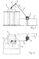
- the Fign. 1 and 2 show an overall illustration of a carding machine 1, which is shown only partially here, and which is followed by a drafting unit 2 in relation to the strip running direction, to which in turn a can can 3 is connected downstream.
- a pot is turned off in a conventional manner, in which the sliver is stored in controlled loops.
- the can stock 3 is provided with a can changer, which offers space for a total of three sliver cans 4.
- the sliver is provided with the reference numeral 5.
- a controlled stretching of the sliver coming from the carding 1 takes place, so as to improve the structure and in particular the uniformity of the sliver.
- Such drafting systems are known, for. B. from the Swiss patent CH 692 349.
- a drafting system often consists of several pairs of rollers, wherein at least the last pair of rollers with a higher, individually adjustable speed is driven. This speed difference causes the stretching and equalization of the sliver.
- the drafting system 2 is therefore designed as Regulierstreckwerk and this has a main drive and a separate, fast-reacting regulating drive.
- the main drive has a fixed, but in size programmable translation to the card 1.
- the Regulierantrieb has a fixed, but in its size but also programmable basic translation for driving the can stack 3.
- the last pair of rollers or possibly the last pairs of rollers of the drafting system 2 which are often referred to as drafting system exit rollers, can accelerate or retard in the short term by the fast-reacting Regulierantrieb compared to the basic translation.
- a fast-acting servo drive z. B. can be the output rollers with a frequency in the millisecond range up to 25% change in their speed.
- Such a rapid change in speed can not follow the drafting unit 2 downstream can Stock 3, since its mechanical drive components react too slow. As a result, there are almost permanent differences in speed.
- the arm 7 is kept under constant counter pressure, so that the sliver 5 remains evenly stretched on its way from the drafting to the can cane. This tension is so low that the structure of the sliver, as this leaves the drafting system 2, is no longer affected.
- a short stand 11 On the top of the can stock a short stand 11 is fixed, which carries at its upper end the bearing for the pivot axis 6 of the arm 7.
- the arm 7 is therefore pivotable about the axis 6, wherein damping elements 16 in the region of the pivot axis 6 exert a progressive damping effect on the rotational movement of the arm, d. H. the greater the speed of rotation of the arm 7, the greater the damping.
- the long lever of the arm 7 consists of a tube 9, at the free end of which the already described roller 8 is freely rotatably mounted.
- the tube 9 is made of a very light, but low-vibration and high-strength material such. B. carbon fiber.
- the short lever of the arm 7 is formed by the weight member 10.
- the weight element 10 sits as close as possible to the pivot axis 6 of the arm so as to bring the mass inertia forces close to the pivot center.
- the weight element 10 is screwed via an adjusting thread 12 with lock nut 13 in the arm 7, wherein by adjusting this thread, the leverage of the weight element can be adjusted.
- the counterweight for the long arm 7 and the roller 8 serving weight element 10 is so dimensioned and balanced that the arranged at the free end of the tube 9 roller 8 always exerts a certain tension on the guided over this roller 8 sliver 5. It is advantageous if the sliver 5, as shown in FIG. 3 reveals, is guided in the middle position of the arm 7 in a deflection angle of about 90 ° on the roller 8.
- Fig. 4 reveals in another view that the deflection means for the sliver except the displaceable roller 8 still another role 14 belongs.
- the further roller 14 is freely rotatably mounted on the pivot axis 6 of the arm 7. Furthermore, the roller 14 is arranged so that the fiber sliver guided over it 5 then passes vertically into the arranged below Kannenstock 3.
- the pivoting movement of the roller bearing arm 7 is limited by two end positions, which are each detectable.
- a first signal transmitter 15a for the first end position of the arm, and a second signal transmitter 15b for the second end position of the arm is integrated into the pivot joint.
- Intermediate layers of the arm 7, however, are not sensory detected, but rather a signal is released only when the arm 7 approaches one of its two end positions at least.
- Fig. 6 also shows a damping element 16, which operates progressively and exerts a higher damping force on the pivot axis 6 of the arm, the greater the displacement speed of the arm. This damping leads to a calming of the arm with respect to short-wave oscillation amplitudes.
- the band tension of the guided over sliver 5 is kept constant, also short and long-wave translation changes are well balanced.
- the detection signals of the limit switches 15a, 15b are sent to a central control unit, which calculates therefrom a speed change for the basic setting of the can stack 3.
- Approaches z As the arm 7 with its role 8 of the lower end position, which is equivalent to a reduction of the sliver length between drafting and caning, a slowing down of the basic speed of the can stack 3 is calculated by the central control unit. Conversely, the arm 7 increases with its role 8, which is equivalent to an elongation of the sliver section between drafting and Kannenstock, the basic speed of the can stack is increased, and thus the driving speed of the can can.
- the central control unit is connected to a controller, which gives appropriate drive commands, so as to make an adjustment and thus Einjust suits the basic translation of Regulierstreckwerks to can-can. Furthermore, the time interval which has elapsed since the last signal output by the signal transmitters 15a, 15b enters the control loop. The larger this time interval, the lower the adjustments made by the central control unit to the speed of the fuel can drive. This consideration of time data leads to a significant calming of the control behavior, and in this way automatically the optimal basic translation is found.
Landscapes
- Engineering & Computer Science (AREA)
- Textile Engineering (AREA)
- Preliminary Treatment Of Fibers (AREA)
- Spinning Or Twisting Of Yarns (AREA)
- Coiling Of Filamentary Materials In General (AREA)
Description
Die Erfindung betrifft eine Fasertransport und -ablegevorrichtung nach dem Oberbegriff des Patentanspruchs 1The invention relates to a fiber transport and -ablegevorrichtung according to the preamble of
Aus der Patentschrift CH 692 349 ist eine Vorrichtung bekannt, bei der das die Karde verlassende Faserband zunächst in ein Streckwerk und von dort in den Kannenstock gelangt, welcher das Faserband in Form von Schlaufen in der Kanne ablegt. Das Streckwerk ist als Regulierstreckwerk ausgebildet und unmittelbar auf der Oberseite des Kannenstocks angeordnet. Auf diese Weise läßt sich, was in der Patentschrift CH 692 349 als besonders vorteilhaft herausgestellt ist, der Abstand zwischen dem Ausgang des Regulierstreckwerks und der Bandeintrittsöffnung des Kannenstocks sehr gering halten.From patent CH 692 349 a device is known, in which the sliver leaving the card first passes into a drafting system and from there into the can stock, which deposits the sliver in the form of loops in the pot. The drafting system is designed as Regulierstreckwerk and arranged directly on the top of the can stock. In this way, which is found to be particularly advantageous in the patent CH 692 349, the distance between the output of Regulierstreckwerks and the band inlet opening of the can can be kept very low.
Steuerungstechnisch ist die Vorrichtung gemäß der Schweizer Patentschrift sehr anspruchsvoll. Das grundsätzliche Problem besteht darin, daß die Arbeitsgeschwindigkeit von Karde einerseits, Streckwerk andererseits und schließlich des Kannenstockes in geeigneter Weise aufeinander abgestimmt werden muß. Geschwindigkeitsdifferenzen müssen ausgeglichen bzw. ausreguliert werden. Hierzu wird gemäß der schweizerischen Patentschrift der Weg beschritten, in den Regelkreis sowohl das Regulierstreckwerk, wie auch den Antriebsmotor der Karde einzubeziehen. Dies setzt voraus, daß die einzelnen Bestandteile steuerungstechnisch miteinander verknüpft sind. In der Praxis stellt sich hingegen häufig das Problem, an eine vorhandene Karde einen Kannenstock mit zwischengeschaltetem Streckwerk zusätzlich oder nachträglich anzubauen. In solchen Fällen ist es häufig nicht möglich oder mit zu hohem technischen Aufwand verbunden, im Sinne einer Gesamtregelung des Systems in die Geschwindigkeitssteuerung der Karde einzugreifen.Control technology, the device according to the Swiss patent is very demanding. The fundamental problem is that the speed of the card on the one hand, drafting on the other hand and finally the can stock must be suitably coordinated with each other. Speed differences must be compensated or regulated. For this purpose, according to the Swiss patent, the way is taken to include in the loop both the Regulierstreckwerk, as well as the drive motor of the card. This assumes that the individual components are linked to each other in terms of control technology. In practice, however, there is often the problem of additionally or subsequently growing a can can with an intermediate drafting device on an existing carding machine. In such cases, it is often not possible or associated with too much technical effort to intervene in the sense of overall control of the system in the speed control of the card.
Die US 5,774,940 offenbart eine Vorrichtung, bei der bei vorgegebener Kardengeschwindigkeit eine Regelung sowohl der Walzenpaare des Streckwerkes erfolgt, wie auch eine getrennte Regelung des Kannenstockantriebs. Zwischen dem Regulierstreckwerk und dem Kannenstock wird das Faserband als frei durchhängende Schlaufe geführt. Ein Niveausensor erfaßt die Höhe dieser Schlaufe, aus diesem Signal wird über einen Prozeßrechner eine Geschwindigkeitsanpassung für einerseits Regulierstreckwerk und andererseits die Ablegegeschwindigkeit des Kannenstocks hergeleitet.US 5,774,940 discloses a device in which, for a given carding speed, a regulation of both the roller pairs of the drafting system takes place, as well as a separate control of Kannenstockantriebs. Between the Regulierstreckwerk and the Kannenstock the sliver is guided as a freely sagging loop. A level sensor detects the height of this loop, from this signal is derived via a process computer, a speed adjustment for one hand Regulierstreckwerk and on the other hand, the depositing speed of the can can.
In der Praxis hat sich herausgestellt, daß bei modernen Karden, welche mit hohen Bandgeschwindigkeiten und kurzweiliger Regelung des Regulierstreckwerkes arbeiten, bei Regelung der Ablegegeschwindigkeit des Kannenstockes mittels z. B. eines sehr schnell arbeitenden Servoantriebs die Mechanik des Kannenstocks überfordert ist, der kurzweiligen Regelung des Regulierstreckwerkes ausreichend schnell zu folgen. Der Grund hierfür liegt in den relativ großen beweglichen Massen des Kannenstocks, die im Falle einer kurzfristigen Geschwindigkeitsanpassung zu hohen mechanischen Kräften insbesondere auf die Lagerung des rotierenden Kopfes des Kannenstockes führen.In practice, it has been found that in modern cards, which work with high belt speeds and entertaining control of Regulierstreckwerkes when regulating the depositing speed of Kannenstockes by means of z. As a very fast-working servo drive, the mechanics of the can-head is overwhelmed, the entertaining control of Regulierstreckwerkes sufficiently fast to follow. The reason for this lies in the relatively large moving masses of the can cane, which in the case of a short-term speed adjustment lead to high mechanical forces, in particular to the bearing of the rotating head of the can-can.
Aus der GB1 436 029 A ist eine Vorrichtung bekannt, bei welcher die Faser zum Ausgleich der Faserbandlänge umgelenkt wird. Hierzu dient ein zwei Abschnitte aufweisendes Rohr, welches um die Achse des ersten, horizontalen Abschnitts drehbar gelagert ist, wobei der zweite Abschnitt gegenüber dem ersten abgewinkelt ist. Beim Verlassen dieses zweiten Abschnitts wird das Faserband in Gestalt einer Schlaufe umgelenkt, und gelangt dann über eine weitere Abwinklung zu dem Kannenstock. Ist das Band wenig belastet, nimmt das Rohr seine abgesenkte Position ein. Bei Verkürzung der das Rohr durchlaufenden Faser wird der abgewinkelte Teil des Rohres entsprechend der Faserkürzung angehoben, der daraus resultierende Drehwinkel des ersten Rohrteils wird detektiert, und die Fasergeschwindigkeit angepaßt. Die durch das Rohr auf die Faser ausgeübte Spannung ist vom Drehwinkel des Rohres abhängig. Diese Spannung kann aber Einfluß auf die Bandqualität der Faser haben.From GB1 436 029 A a device is known in which the fiber is deflected to compensate for the sliver length. Serves for this purpose a tube having two sections, which is rotatably mounted about the axis of the first, horizontal portion, wherein the second portion is angled relative to the first. When leaving this second section, the sliver is deflected in the form of a loop, and then passes over another bend to the can-stock. If the tape is lightly loaded, the tube assumes its lowered position. When shortening the fiber passing through the tube, the angled portion of the tube is raised in accordance with the fiber shortening, the resulting angle of rotation of the first tube portion is detected, and the fiber speed is adjusted. The tension exerted by the tube on the fiber depends on the angle of rotation of the tube. However, this tension can have an influence on the strip quality of the fiber.
Der Erfindung liegt die Aufgabe zugrunde, eine mit einfachen steuerungstechnischen Mitteln arbeitende Fasertransport und -ablegevorrichtung zum Anschluß an eine Karde zu schaffen, welche hinter dem Streckwerkausgang die Anpassung und den Ausgleich der Bandgeschwindigkeit ohne Beeinflussung der Bandqualität ermöglicht.The invention has for its object to provide a working with simple control means fiber transport and -ablegevorrichtung for connection to a card, which allows the adjustment and the compensation of the belt speed without affecting the tape quality behind the drafting system output.
Die Lösung dieser Aufgabe ist bei einer gattungsgemäßen Fasertransport und -ablegevorrichtung gekennzeichnet durch am freien Ende eines um eine Schwenkachse verschwenkbaren und zur Aufrechterhaltung einer gewissen Bandspannung einen Gegendruck auf das Faserband ausübenden Arms angeordnete Umlenkmittel, über die das Faserband in einem Umlenkwinkel geführt ist.The solution to this problem is in a generic fiber transport and -ablegevorrichtung characterized by at the free end of a pivotable about a pivot axis and to maintain a certain belt tension a back pressure on the sliver-performing arm arranged deflecting means over which the sliver is guided in a deflection.
Eine solche Fasertransport und -ablegevorrichtung ermöglicht durch einfache steuerungstechnische Mittel die Anpassung und den Ausgleich der Bandgeschwindigkeiten hinter dem feinregulierenden Streckwerk. Erfindungsgemäß beruht die Regelung auf einer örtlichen Verlagerung von Umlenkmitteln für das Faserband, wobei diese Umlenkmittel. aus einem um eine Schwenkachse verschwenkbaren Arm bestehen, an dessen freiem Ende eine Rolle frei drehbar gelagert sein kann, über die das Faserband geführt und umgelenkt ist. Das Faserband läuft daher nicht auf direktem Wege von dem letzten Walzenpaar des Streckwerks zu dem Kannenstock, sondern es nimmt den "Umweg" über die verlagerbaren Umlenkmittel. Dies führt zum einen zur automatischen Aufrechterhaltung einer gewissen Bandspannung und damit zur Wahrung der das Streckwerk verlassenden Bandqualität. Zum anderen ergibt sich eine Detektionsmöglichkeit aufgrund der örtlichen Verlagerung der Umlenkmittel. Hierzu sind diskrete Signalgeber für eine erste und für eine zweite Endlage der Umlenkmittel vorgesehen. Erfaßt wird daher nicht die Größe der örtlichen Verlagerung der Umlenkmittel über den gesamten möglichen Bewegungsbereich, sondern es werden nur diskrete Endlagen bzw. eine Annäherung an solche Endlagen erfaßt.By means of simple control technology, such a fiber transport and depositing device makes it possible to adapt and equalize the belt speeds behind the fine-regulating drafting system. According to the invention, the control is based on a local displacement of deflecting means for the sliver, wherein these deflecting means. consist of an arm pivotable about a pivot axis, at the free end of a roller can be freely rotatably supported, over which the sliver is guided and deflected. Therefore, the sliver does not run directly from the last pair of rollers of the drafting to the can stock, but it takes the "detour" on the displaceable deflection. On the one hand, this leads to the automatic maintenance of a certain belt tension and thus to the maintenance of the belt quality leaving the drafting system. On the other hand results in a detection option due to the local displacement of the deflection. For this purpose, discrete signal transmitters are provided for a first and for a second end position of the deflection means. It is therefore not the size of the local displacement of the deflection over the entire possible range of motion, but only discrete end positions or an approximation to such end positions are detected.
Schließlich sind erfindungsgemäß Mittel zur Veränderung der Antriebsgeschwindigkeit des Kannenstocks bei einer Signalabgabe durch einen der Signalgeber und in Abhängigkeit von dem seit der letzten Signalabgabe verstrichenen Zeitintervall vorgesehen. Nur wenn eine der Endlagen erreicht wird, erfolgt eine Anpassung der Grundübersetzung durch Eingriff in die Arbeitsgeschwindigkeit des Kannenstocks. Je länger die Zeitspanne zwischen dem aufeinanderfolgenden Erreichen zweier Endlagen ist, um so geringer ist die Geschwindigkeitsanpassung des Kannenstocks.Finally, according to the invention means are provided for changing the drive speed of the can stack in the case of a signal output by one of the signal transmitters and in dependence on the time interval which has elapsed since the last signal output. Only when one of the end positions is reached, is an adaptation of the basic ratio by intervention in the operating speed of the can-can stock. The longer the time span between the successive reaching of two end positions, the lower the speed adjustment of the can cane.
Ein Eingriff in die oftmals vollständig unabhängige Steuerung der Karde ist nicht erforderlich, weshalb sich die erfindungsgemäße Faserbandtransport und -ablegevorrichtung auch zur Nachrüstung sowie zum nachträglichen Anbau an eine vorhandene Karde eignet. Da als Ausgangsgröße der Regelung nur zwei Endlagen und nicht z. B. sämtliche dazwischenliegenden Werte erfaßt werden, ist der steuerungstechnische Aufwand trotz der erreichbaren hohen Bandgeschwindigkeiten gering.An intervention in the often completely independent control of the card is not required, which is why the fiber sliver transport and -ablegevorrichtung invention also suitable for retrofitting and for retrofitting to an existing card. Since only two end positions and not z. B. all intermediate values are detected, the control engineering effort is low despite the achievable high belt speeds.
Von Vorteil ist schließlich der ruhige Lauf des Faserbandes, indem dieses über die am freien Ende des Arms angeordneten Umlenkmittel geführt ist, welche die Qualität des Faserbandes, so wie dieses das Streckwerk verläßt, nicht mehr beeinträchtigen können. Gerade bei den hohen angestrebten Bandgeschwindigkeiten zeichnet sich eine solche Bandführung durch einen ruhigeren Transport des Faserbandes aus, als z. B. im Falle einer frei durchhängenden Schlaufe, wie sie in Verbindung mit einem stufenlos arbeitenden Niveausensor in der US 5,774,940 beschrieben ist. Ein zusätzlicher Nachteil eines die durchhängende Faserband-Schlaufe erfassenden Niveausensors besteht darin, daß das undefinierte Durchhängen der Faserbandschlaufe gerade zu solchen Fehlverzügen im Faserband führen kann, die vorher aufwendig durch das Regulierstreckwerk beseitigt wurden.Of advantage is finally the smooth running of the sliver by this is performed on the arranged at the free end of the arm deflection, which can no longer affect the quality of the sliver, as this leaves the drafting. Especially at the high desired tape speeds, such a tape guide is characterized by a quieter transport of the sliver, as z. B. in the case of a freely sagging loop, as described in connection with a continuously operating level sensor in US 5,774,940. An additional disadvantage of a sagging sliver loop-detecting level sensor is that the undefined sagging of the sliver loop can just lead to such Fehlverletzungen in the sliver, which were previously eliminated consuming by the Regulierstreckwerk.
Mit einer bevorzugten Ausgestaltung der Fasertransport und -ablegevorrichtung wird vorgeschlagen, daß zur Detektion der beiden Endlagen jeweils zwei Signalgeber geringfügig versetzt zueinander angeordnet sind. Auf diese Weise kann auch eine Annäherung an die Endlage bereits signaltechnisch erfaßt, und dementsprechend die Steuerung verfeinert werden. Als Signalgeber kommen vorzugsweise Näherungsschalter zur Anwendung.With a preferred embodiment of the fiber transport and -ablegevorrichtung it is proposed that for the detection of the two end positions each two signal transmitters are arranged slightly offset from one another. In this way, an approach to the end position can already be detected by signal technology, and accordingly the control can be refined. Proximity switches are preferably used as signal transmitters.
Für den verschwenkbaren Arm wird eine besonders leichtgewichtige und damit nahezu trägheitslose Konstruktion vorgeschlagen, bei welcher der Arm aus einem dünnwendigen Rohr besteht. Besonders geeignet ist hierfür ein Rohr aus Kohlefaser, welches den Vorteil geringen Gewichts mit hoher Festigkeit und weitgehender Schwingungsfreiheit verbindet. Ein solcher Arm arbeitet mit sehr geringen Trägheitsmomenten und einem daher guten Ansprechverhalten auf jede Längung oder Kürzung des über den Arm umgelenkten Faserbahdes.For the pivoting arm a particularly lightweight and thus almost inertia-free construction is proposed, in which the arm consists of a thin-walled tube. Particularly suitable for this purpose is a tube made of carbon fiber, which combines the advantage of low weight with high strength and extensive freedom from vibration. Such an arm works with very low moments of inertia and therefore a good response to any elongation or reduction of the deflected over the arm Faserbahdes.
Zur Verbesserung des Ansprechverhaltens der Umlenkmittel auf jede Längenänderung des Faserbandes trägt ferner eine auf der Schwenkachse für den Arm ortsfest gelagerte weitere Rolle bei, welche in diesem Fall als weiteres Umlenkmittel dient. Vorzugsweise ist hierbei die Schwenkachse für den Arm über dem Kannenstock angeordnet, und das Faserband ist zwischen der weiteren Rolle und dem Kannenstock senkrecht geführt, so daß das Faserband auf kürzestem Wege und von oben senkrecht nach unten in den Kannenstock gelangt.To improve the response of the deflection on each change in length of the sliver further contributes to a stationary on the pivot axis for the arm further role, which serves as a further deflection in this case. Preferably, in this case, the pivot axis is arranged for the arm on the can stock, and the sliver is guided vertically between the other role and the can stock, so that the sliver passes on the shortest path and from above vertically down into the can stock.
Zur Erzielung eines exakten Ansprechverhaltens der Umlenkmittel ist es von Vorteil, wenn diese nur entgegen einer gewissen Gegenkraft verlagerbar sind, wozu vorzugsweise ein Dämpfungsmechanismus eingesetzt wird. Dementsprechend ist eine Ausgestaltung der Erfindung dadurch gekennzeichnet, daß die Umlenkmittel mit einem in Verlagerungsrichtung wirkenden Dämpfungselement mit progressiver Dämpfungs-Kennlinie versehen sind, so daß für die Regulierung des Kannenstocks ungünstige Schwingungen weitestgehend vermieden werden. Vorzugsweise ist das Dämpfungselement in der Weise angeordnet, daß dieses dämpfend auf die Schwenkachse des verschwenkbaren Arms wirkt.In order to achieve an exact response of the deflection, it is advantageous if they are displaceable only against a certain counterforce, for which purpose preferably a damping mechanism is used. Accordingly, an embodiment of the invention is characterized in that the deflection means with a in the direction of displacement acting damping element are provided with progressive damping characteristic, so that unfavorable vibrations are largely avoided for the regulation of Kannenstocks. Preferably, the damping element is arranged in such a way that this acts damping on the pivot axis of the pivotable arm.
Weitere Einzelheiten der Erfindung werden nachfolgend anhand eines Ausführungsbeispieles und unter Bezugnahme auf die Zeichnungen erläutert. Darin zeigen:
- Fig. 1
- in einer Seitenansicht ein an eine Karde angebautes Streckwerk sowie einen diesem Streckwerk nachgeschalteten Kannenstock, welcher hier zur Aufnahme von insgesamt drei Faserbandkannen vorbereitet ist;
- Fig. 2
- die Gegenstände nach Fig. 1 in einer Draufsicht;
- Fig. 3
- in einer Schnittdarstellung einen auf dem Kannenstock angeordneten Arm, über den das Faserband auf dem Weg vom Streckwerk zum Kannenstock umgelenkt wird;
- Fig. 4
- den Arm nach Fig. 3 in einer gegenüber Fig. 3 um 90° verdrehten Ansicht;
- Fig. 5
- eine vergrößert dargestellte Einzelheit der Fig. 3 und
- Fig. 6
- einen Schnitt in der in Fig. 5 eingezeichneten Ebene VI-VI durch die Lagerung des verschwenkbaren Arms.
- Fig. 1
- in a side view of a drafting device attached to a carding machine and a can stock connected downstream of this drafting system, which here is prepared for receiving a total of three sliver cans;
- Fig. 2
- the objects of Figure 1 in a plan view.
- Fig. 3
- in a sectional view of an arranged on the cans arm, over which the sliver is deflected on the way from the drafting to Kannenstock;
- Fig. 4
- the arm of Figure 3 in a relation to Figure 3 rotated by 90 ° view ..;
- Fig. 5
- an enlarged detail shown in FIG. 3 and
- Fig. 6
- a section in the drawn in Fig. 5 plane VI-VI by the mounting of the pivotable arm.
Die Fign. 1 und 2 zeigen in einer Gesamtdarstellung eine hier nur teilweise dargestellte Karde 1, der in Bezug auf die Bandlaufrichtung ein Streckwerk 2 nachgeschaltet ist, dem wiederum ein Kannenstock 3 nachgeschaltet ist. In dem Kannenstock 3 ist in an sich bekannter Weise eine Kanne abgestellt, in welcher das Faserband in Schlaufen kontrolliert abgelegt wird. Im vorliegenden Fall ist der Kannenstock 3 mit einem Kannenwechsler versehen, welcher Platz für insgesamt drei Faserbandkannen 4 bietet. Das Faserband ist mit dem Bezugszeichen 5 versehen.The Fign. 1 and 2 show an overall illustration of a
In dem Streckwerk 2 erfolgt ein kontrolliertes Strecken des von der Karde 1 kommenden Faserbandes, um so die Struktur und insbesondere die Gleichmäßigkeit des Faserbandes zu verbessern. Auch solche Streckwerke sind bekannt, z. B. aus der schweizerischen Patentschrift CH 692 349. Ein Streckwerk besteht häufig aus mehreren Walzenpaaren, wobei zumindest das letzte Walzenpaar mit einer höheren, individuell regelbaren Geschwindigkeit angetrieben ist. Dieser Geschwindigkeitsunterschied bewirkt die Streckung und Vergleichmäßigung des Faserbandes.In the
Das Streckwerk 2 ist daher als Regulierstreckwerk ausgebildet und verfügt hierzu über einen Hauptantrieb sowie einen getrennten, schnell reagierenden Regulierantrieb. Der Hauptantrieb weist eine feste, jedoch in ihrer Größe programmierbare Übersetzung zur Karde 1 auf. Der Regulierantrieb weist eine feste, in ihrer Größe aber ebenfalls programmierbare Grundübersetzung zum Antrieb des Kannenstocks 3 auf.The
Zur Erzielung der gewünschten Struktur des Faserbandes lassen sich das letzte Walzenpaar bzw. ggf. auch die letzten Walzenpaare des Streckwerks 2, welche häufig auch als Streckwerksausgangswalzen bezeichnet werden, kurzfristig durch den schnell reagierenden Regulierantrieb gegenüber der Grundübersetzung beschleunigen oder verzögern. Mittels eines schnell arbeitenden Servoantriebs z. B. lassen sich die Ausgangswalzen mit einer Frequenz im Millisekunden-Bereich bis zu 25 % in ihrer Geschwindigkeit ändern. Einer derartig schnellen Geschwindigkeitsänderung kann der dem Streckwerk 2 nachgeschaltete Kannenstock 3 nicht folgen, da seine mechanischen Antriebskomponenten zu träge reagieren. Im Ergebnis kommt es daher zu nahezu dauernden Geschwindigkeitsdifferenzen.To achieve the desired structure of the sliver, the last pair of rollers or possibly the last pairs of rollers of the
Aufgrund dieser unterschiedlichen Dynamik des Regulierstreckwerks einerseits und des Kannenstocks andererseits kommt es ferner zu Änderungen der wirksamen Bandlänge des Faserbandes auf dem Weg vom Streckwerk 2 zum Kannenstock 3. Diese Längenänderungen werden dadurch kurzfristig ausgeglichen, daß das Faserband 5 auf seinem Weg vom Streckwerk 2 zum Kannenstock 3 über das freie Ende eines um eine Schwenkachse 6 verschwenkbaren Arms 7 geführt ist. Infolge seiner Schwenkbarkeit um die Schwenkachse 6 bildet der Arm 7 bzw. eine an seinem freien Ende frei drehbar gelagerte Rolle 8 ein entsprechend der wirksamen Faserbandlänge verlagerbares Umlenkmittel für das Faserband. Durch eine definierte Gegenkraft, welche vorzugsweise durch ein Gegengewicht erzeugt wird, wird der Arm 7 unter konstantem Gegendruck gehalten, so daß das Faserband 5 auf seinem Weg vom Streckwerk zum Kannenstock gleichmäßig gespannt bleibt. Diese Spannung ist so gering, daß die Struktur des Faserbandes, so wie dieses das Streckwerk 2 verläßt, nicht mehr beeinflußt wird.Due to this different dynamics of Regulierstreckwerks one hand, and the Kannenstocks on the other hand, there are also changes in the effective band length of the sliver on the way from the drafting 2 to
Anhand der Fign. 3 bis 6 werden nachfolgend Einzelheiten des in erster Linie aus dem Arm 7 und der daran frei gelagerten Rolle 8 zusammengesetzten Umlenkmittels erläutert.Based on the Fign. 3 to 6, details of the deflecting means composed primarily of the
Auf der Oberseite des Kannenstocks ist ein kurzer Ständer 11 befestigt, der an seinem oberen Ende die Lagerung für die Schwenkachse 6 des Arms 7 trägt. Der Arm 7 ist daher um die Achse 6 schwenkbar, wobei Dämpfungselemente 16 im Bereich der Schwenkachse 6 eine progressive Dämpfungswirkung auf die Drehbewegung des Arms ausüben, d. h. je größer die Verdrehgeschwindigkeit des Arms 7, desto größer ist die Dämpfung. Der lange Hebel des Arms 7 besteht aus einem Rohr 9, an dessen freiem Ende die bereits beschriebene Rolle 8 frei drehbar gelagert ist. Das Rohr 9 besteht aus einem sehr leichten, jedoch schwingungsarmen und hochfesten Material wie z. B. Kohlefaser.On the top of the can stock a
Der kurze Hebel des Arms 7 wird durch das Gewichtselement 10 gebildet. Das Gewichtselement 10 sitzt möglichst nah an der Schwenkachse 6 des Arms, um so die Massenträgheitskräfte nahe an den Schwenkmittelpunkt zu bringen. Das Gewichtselement 10 ist über ein Einstellgewinde 12 mit Kontermutter 13 in den Arm 7 eingeschraubt, wobei durch Einstellung dieses Gewindes die Hebelkraft des Gewichtselements eingestellt werden kann.The short lever of the
Das als Gegengewicht für den langen Arm 7 sowie die Rolle 8 dienende Gewichtselement 10 ist so dimensioniert und austariert, daß die am freien Ende des Rohrs 9 angeordnete Rolle 8 stets eine gewisse Spannung auf das über dieser Rolle 8 geführte Faserband 5 ausübt. Hierbei ist es von Vorteil, wenn das Faserband 5, wie dies Fig. 3 erkennen läßt, in der mittleren Stellung des Arms 7 in einem Umlenkwinkel von ca. 90° über die Rolle 8 geführt ist.The counterweight for the
Die Fig. 4 läßt in einer anderen Ansicht erkennen, daß zu den Umlenkmitteln für das Faserband außer der verlagerbaren Rolle 8 noch eine weitere Rolle 14 gehört. Die weitere Rolle 14 ist frei drehbar auf der Schwenkachse 6 des Arms 7 gelagert. Des weiteren ist die Rolle 14 so angeordnet, daß das über sie geführte Faserband 5 anschließend senkrecht in den darunter angeordneten Kannenstock 3 gelangt.Fig. 4 reveals in another view that the deflection means for the sliver except the
Gemäß den Fign. 5 und 6 ist die Schwenkbewegung des wälzgelagerten Arms 7 durch zwei Endlagen begrenzt, die jeweils detektierbar sind. Hierzu ist ein erster Signalgeber 15a für die erste Endlage des Arms, und ein zweiter Signalgeber 15b für die zweite Endlage des Arms in das Schwenkgelenk integriert. Vorzugsweise gehört zu jedem der beiden Signalgeber 15a, 15b noch ein hierzu örtlich geringfügig vorgelagerter Vorsignalgeber, so daß bereits Annäherungen an die Endlagen detektierbar sind. Zwischenlagen des Arms 7 hingegen werden nicht sensorisch erfaßt, vielmehr erfolgt eine Signalabgabe erst dann, wenn sich der Arm 7 einer seiner beiden Endlagen zumindest nähert.According to FIGS. 5 and 6, the pivoting movement of the
Fig. 6 zeigt ferner ein Dämpfungselement 16, welches progressiv arbeitet und eine um so höhere Dämpfungskraft auf die Schwenkachse 6 des Arms ausübt, je größer die Verlagerungsgeschwindigkeit des Arms ist. Diese Dämpfung führt zu einer Beruhigung des Arms gegenüber kurzwelligen Schwingungsamplituden.Fig. 6 also shows a damping
Durch die besonders leichtgewichtigte Bauweise des Arms 7 wird die Bandspannung des darüber geleiteten Faserbandes 5 konstant gehalten, außerdem werden kurz- und langwellige Übersetzungsänderungen gut ausgeglichen.Due to the particularly lightweight construction of the
Die Detektionssignale der Endlagen-Signalgeber 15a, 15b werden an eine zentrale Steuereinheit gegeben, die hieraus eine Geschwindigkeitsveränderung für die Grundeinstellung des Kannenstocks 3 errechnet. Nähert sich z. B. der Arm 7 mit seiner Rolle 8 der unteren Endlage, was einer Kürzung der Faserbandlänge zwischen Streckwerk und Kannenstock gleichkommt, wird von der zentralen Steuereinheit eine Verlangsamung der Grundgeschwindigkeit des Kannenstocks 3 errechnet. Steigt umgekehrt der Arm 7 mit seiner Rolle 8, was einer Längung des Faserbandabschnittes zwischen Streckwerk und Kannenstock gleichkommt, wird die Grundgeschwindigkeit des Kannenstocks erhöht, und damit auch die Antriebsgeschwindigkeit des Kannenstocks. Zu diesem Zweck ist die zentrale Steuereinheit an einen Regler angeschlossen, der entsprechende Antriebsbefehle gibt, um so eine Anpassung und damit Einjustierung der Grundübersetzung des Regulierstreckwerks zum Kannenstock vorzunehmen. In den Regelkreis geht ferner das seit der letzten Signalabgabe durch die Signalgeber 15a, 15b verstrichene Zeitintervall ein. Je größer dieses Zeitintervall, desto geringer fallen die von der zentralen Steuereinheit errechneten Anpassungen der Geschwindigkeit am Kannenstockantrieb aus. Diese Berücksichtigung auch von Zeitdaten führt zu einer deutlichen Beruhigung des Regelverhaltens, und auf diese Weise wird automatisch die optimale Grundübersetzung gefunden.The detection signals of the
- 11
- Kardeteasel
- 22
- Streckwerkdrafting system
- 33
- Kannenstockcan Stock
- 44
- FaserbandkanneSliver
- 55
- Faserbandsliver
- 66
- Schwenkachseswivel axis
- 77
- Armpoor
- 88th
- Rollerole
- 99
- Rohrpipe
- 1010
- Gewichtselementweight element
- 1111
- Ständerstand
- 1212
- Einstellgewindeadjustment threads
- 1313
- Kontermutter für das GewichtselementLock nut for the weight element
- 1414
- Rollerole
- 15a15a
- Signalgebersignaler
- 15b15b
- Signalgebersignaler
- 1616
- Dämpfungdamping
Claims (10)
- Fibre conveying and depositing device for connection to a carding machine, in which the fibre strip, after exiting from the carding machine, is passed through a draw frame (2) consisting of at least two driven roller pairs and then reaches a can coiler (3), wherein the draw frame (2) has a main drive and a regulating drive for the last roller pair, comprising:a. deflection means (8) for the fibre strip (5) arranged between the last roller pair of the draw frame (2) and the can coiler (3), which deflection means can be displaced in order to compensate for the length of the fibre strip;b. signal transducers (15a, 15b) for a first and second end position of the deflection means (8), andc. means for changing the speed of the can coiler drive when a signal is output by one of the signal transducers (15a, 15b) and as a function of the time interval that has elapsed since the last signal was output,characterised by deflection means (8) arranged at the free end of an arm (7) which can pivot about a pivot axle (6) and which exerts a counter-pressure on the fibre strip (5) so as to maintain a certain strip tension, via which deflection means the fibre strip (5) is guided at a deflection angle.
- Fibre conveying and depositing device according to Claim 1, characterised in that in each case two signal transducers (15a, 15b) are arranged slightly offset with respect to one another in order to detect the two end positions.
- Fibre conveying and depositing device according to Claim 1 or 2, characterised by proximity switches as signal transducers (15a, 15b).
- Fibre conveying and depositing device according to one of Claims 1 to 3, characterised by a roller (8) arranged in a freely rotatable manner on the arm (7) as deflection means.
- Fibre conveying and depositing device according to Claim 4, characterised in that the roller (8) and the arm (7) are prestressed against the fibre strip (5) by means of a weight element (10) arranged on the arm (7).
- Fibre conveying and depositing device according to one of Claims 4 or 5, characterised in that the pivotable arm (7) consists of a thin-walled tube (9), preferably made from carbon fibre.
- Fibre conveying and depositing device according to one of Claims 4 to 6, characterised by a further roller (14) which is mounted in a stationary manner on the pivot axle (6) for the arm as further deflection means.
- Fibre conveying and depositing device according to Claim 7, characterised in that the pivot axle (6) for the arm (7) is arranged above the can coiler (3), and in that the fibre strip (5) is guided vertically between the further roller (14) and the can coiler (3).
- Fibre conveying and depositing device according to one of Claims 1 to 8, characterised in that the deflection means are provided with a damping element (16) which has a progressive damping characteristic and acts in the direction of displacement.
- Fibre conveying and depositing device according to Claim 5 in conjunction with Claim 9, characterised in that the damping element (16) acts on the pivot axle of the pivotable arm (7).
Applications Claiming Priority (3)
| Application Number | Priority Date | Filing Date | Title |
|---|---|---|---|
| DE10252181A DE10252181B3 (en) | 2002-11-09 | 2002-11-09 | Fiber transport and laying device for connection to a card |
| DE10252181 | 2002-11-09 | ||
| PCT/DE2003/003508 WO2004044291A1 (en) | 2002-11-09 | 2003-10-22 | Fiber conveying and discarding device to be connected to a carder |
Publications (2)
| Publication Number | Publication Date |
|---|---|
| EP1587973A1 EP1587973A1 (en) | 2005-10-26 |
| EP1587973B1 true EP1587973B1 (en) | 2007-01-24 |
Family
ID=32308505
Family Applications (1)
| Application Number | Title | Priority Date | Filing Date |
|---|---|---|---|
| EP03776810A Expired - Lifetime EP1587973B1 (en) | 2002-11-09 | 2003-10-22 | Fiber conveying and discarding device to be connected to a carder |
Country Status (6)
| Country | Link |
|---|---|
| US (1) | US7318254B2 (en) |
| EP (1) | EP1587973B1 (en) |
| CN (1) | CN100410432C (en) |
| AU (1) | AU2003286103A1 (en) |
| DE (2) | DE10252181B3 (en) |
| WO (1) | WO2004044291A1 (en) |
Families Citing this family (6)
| Publication number | Priority date | Publication date | Assignee | Title |
|---|---|---|---|---|
| CN103588006A (en) * | 2013-11-14 | 2014-02-19 | 际华三五三七制鞋有限责任公司 | Method and device for automatically adjusting cutting point positions of rubber shoe surrounding strips |
| CN103723549A (en) * | 2013-12-27 | 2014-04-16 | 绍兴科泰斯纺织品检验有限公司 | Tension adjusting device of cloth inspecting machine |
| DE102015113044A1 (en) * | 2015-08-07 | 2017-02-09 | TRüTZSCHLER GMBH & CO. KG | Device for filling a jug with sliver |
| CN107089555A (en) * | 2017-06-14 | 2017-08-25 | 深圳市铁工机自动化技术有限公司 | A kind of circulating type line concentration bucket for plastic detonating tube |
| DE102017124562A1 (en) * | 2017-10-20 | 2019-04-25 | Maschinenfabrik Rieter Ag | Textile machine network with a belt storage unit for temporary storage of fiber sliver |
| JP7019278B1 (en) * | 2021-09-03 | 2022-02-15 | 旭精機工業株式会社 | Manufacturing method of winding device and winding body |
Family Cites Families (15)
| Publication number | Priority date | Publication date | Assignee | Title |
|---|---|---|---|---|
| US2897550A (en) | 1956-09-27 | 1959-08-04 | Southern States Equipment Corp | Sliver guide for textile coiler |
| GB1436029A (en) | 1973-10-04 | 1976-05-19 | Texctronol | Electromechanical system for controlling the speed of a coiler at the output of a textile carding machine |
| US3938222A (en) * | 1974-10-07 | 1976-02-17 | John D. Hollingsworth On Wheels, Inc. | Tracking guide for planetary coiler |
| DE2543839B1 (en) * | 1975-10-01 | 1976-11-25 | Graf & Co Ag | DEVICE FOR CREATING A UNIFORM TEXTILE FIBER TAPE |
| CH627498A5 (en) * | 1978-04-26 | 1982-01-15 | Zellweger Uster Ag | METHOD AND DEVICE FOR REGULATING TAPE WEIGHT VARIATIONS ON CARD, CARD, AND STRETCHES. |
| DE3523660A1 (en) * | 1985-06-28 | 1987-01-08 | Basf Ag | DEVICE FOR THE PRODUCTION OF A HOLLOW BODY FROM COMPOSITE MATERIAL |
| DE3837596A1 (en) * | 1988-11-05 | 1990-05-10 | Rosink Gmbh & Co Kg | KANNENSTOCK |
| GB2255353B (en) * | 1991-05-01 | 1994-11-30 | Hollingsworth On Wheels John D | Drive between an autoleveller and a coiler |
| IT1276944B1 (en) * | 1995-10-16 | 1997-11-03 | Marzoli & C Spa | DEVICE FOR REGULATION AND CONTROL OF THE TENSION OF THE BELT SOLD BY THE IRONING UNIT OF A CARD TO THE COLLECTION UNIT OF THE |
| IT1292144B1 (en) * | 1996-06-29 | 1999-01-25 | Truetzschler & Co | DEVICE ON A CARD, IN WHICH A VEIL FUNNEL WITH EXTRACTION CYLINDERS IS PROVIDED AT THE OUTPUT OF THE CARD |
| US5774940A (en) * | 1996-07-19 | 1998-07-07 | North Carolina State University | Draftless sliver coiler packaging system for automated textile drafting system |
| IT1293614B1 (en) * | 1996-08-22 | 1999-03-08 | Truetzschler & Co | DEVICE FOR THE TRANSPORT AND PREPARATION OF POTS, IN PARTICULAR BETWEEN TWO CONSECUTIVE IRONING MACHINES IN THE WORKING CYCLE |
| DE19811497A1 (en) * | 1998-03-17 | 1999-09-23 | Rieter Ingolstadt Spinnerei | Method and device for storing a textile fiber material between working elements of spinning machines |
| US6199411B1 (en) * | 1999-03-01 | 2001-03-13 | Sara Lee Corporation | Dyeing range unloader |
| DE10052478A1 (en) * | 2000-10-23 | 2002-05-02 | Bayer Faser Gmbh | Elastic fibre fed into a carton as meandering array by swivel arm at a speed ten per cent faster than the production speed |
-
2002
- 2002-11-09 DE DE10252181A patent/DE10252181B3/en not_active Expired - Fee Related
-
2003
- 2003-10-22 WO PCT/DE2003/003508 patent/WO2004044291A1/en active IP Right Grant
- 2003-10-22 AU AU2003286103A patent/AU2003286103A1/en not_active Abandoned
- 2003-10-22 CN CNB2003801029295A patent/CN100410432C/en not_active Expired - Fee Related
- 2003-10-22 EP EP03776810A patent/EP1587973B1/en not_active Expired - Lifetime
- 2003-10-22 DE DE50306414T patent/DE50306414D1/en not_active Expired - Lifetime
- 2003-10-22 US US10/533,792 patent/US7318254B2/en not_active Expired - Fee Related
Also Published As
| Publication number | Publication date |
|---|---|
| WO2004044291A1 (en) | 2004-05-27 |
| CN100410432C (en) | 2008-08-13 |
| DE10252181B3 (en) | 2004-10-07 |
| US20060196012A1 (en) | 2006-09-07 |
| AU2003286103A1 (en) | 2004-06-03 |
| DE50306414D1 (en) | 2007-03-15 |
| EP1587973A1 (en) | 2005-10-26 |
| WO2004044291B1 (en) | 2004-07-15 |
| US7318254B2 (en) | 2008-01-15 |
| CN1711377A (en) | 2005-12-21 |
Similar Documents
| Publication | Publication Date | Title |
|---|---|---|
| EP0914287B1 (en) | Method for winding up an advancing thread | |
| EP0365931B1 (en) | Method and device for controlling an air jet spinning machine | |
| EP0280038B1 (en) | Calender | |
| EP0165511B1 (en) | Device for winding a yarn supplied at a constant speed on a conical spool | |
| AT398988B (en) | TENSION ADJUSTMENT DEVICE FOR AN ELASTIC TAPE | |
| DE2513981A1 (en) | METHOD AND DEVICE FOR CONTROLLING AND / OR REGULATING THE THREAD TENSION WHEN WINDING A TEXTILE SPOOL | |
| EP0312774B1 (en) | Sliver coiler of a carding machine with an electronic drive | |
| EP0650406B1 (en) | Device for cutting moving material webs to shape | |
| EP1587973B1 (en) | Fiber conveying and discarding device to be connected to a carder | |
| EP0790084B1 (en) | Winding device for bands | |
| EP1781847B1 (en) | Device and method for a carder | |
| CH681156A5 (en) | ||
| EP0593951B1 (en) | Spinning device | |
| DE2059283A1 (en) | Belt guiding and stretching device | |
| DE3723433C2 (en) | Ribbon loom | |
| DE3212176A1 (en) | Web-guide device | |
| EP0012937B1 (en) | Traversing device for yarn winding machines with variable yarn-guiding stroke and stepless collective adjustment of the flange angles of the packages | |
| EP0031843B1 (en) | Flyer for a roving frame | |
| DE3023068C2 (en) | Device for the controlled feeding and pulling of a thread into or out of a thread treatment line | |
| DE2939693C2 (en) | Fleece removal device | |
| EP1947042B1 (en) | Winding apparatus | |
| DE2163161C3 (en) | Thread connector for one along the spindle rows of a spinning machine or the like. movable maintenance device | |
| EP0334016B1 (en) | Device for driving the folding blade of a folding machine | |
| DE4300686A1 (en) | Disentangling and possible separate winding up system for linearly cut multi-layer lines | |
| EP0885668A2 (en) | Coil forming head for forming loops from wire leaving a wire rolling mill |
Legal Events
| Date | Code | Title | Description |
|---|---|---|---|
| PUAI | Public reference made under article 153(3) epc to a published international application that has entered the european phase |
Free format text: ORIGINAL CODE: 0009012 |
|
| 17P | Request for examination filed |
Effective date: 20050226 |
|
| AK | Designated contracting states |
Kind code of ref document: A1 Designated state(s): AT BE BG CH CY CZ DE DK EE ES FI FR GB GR HU IE IT LI LU MC NL PT RO SE SI SK TR |
|
| AX | Request for extension of the european patent |
Extension state: AL LT LV MK |
|
| DAX | Request for extension of the european patent (deleted) | ||
| RBV | Designated contracting states (corrected) |
Designated state(s): CH DE IT LI |
|
| GRAP | Despatch of communication of intention to grant a patent |
Free format text: ORIGINAL CODE: EPIDOSNIGR1 |
|
| GRAS | Grant fee paid |
Free format text: ORIGINAL CODE: EPIDOSNIGR3 |
|
| GRAA | (expected) grant |
Free format text: ORIGINAL CODE: 0009210 |
|
| AK | Designated contracting states |
Kind code of ref document: B1 Designated state(s): CH DE IT LI |
|
| REG | Reference to a national code |
Ref country code: CH Ref legal event code: EP |
|
| REF | Corresponds to: |
Ref document number: 50306414 Country of ref document: DE Date of ref document: 20070315 Kind code of ref document: P |
|
| PLBE | No opposition filed within time limit |
Free format text: ORIGINAL CODE: 0009261 |
|
| STAA | Information on the status of an ep patent application or granted ep patent |
Free format text: STATUS: NO OPPOSITION FILED WITHIN TIME LIMIT |
|
| 26N | No opposition filed |
Effective date: 20071025 |
|
| PGFP | Annual fee paid to national office [announced via postgrant information from national office to epo] |
Ref country code: CH Payment date: 20101025 Year of fee payment: 8 Ref country code: DE Payment date: 20101103 Year of fee payment: 8 |
|
| PGFP | Annual fee paid to national office [announced via postgrant information from national office to epo] |
Ref country code: IT Payment date: 20101027 Year of fee payment: 8 |
|
| REG | Reference to a national code |
Ref country code: CH Ref legal event code: PL |
|
| PG25 | Lapsed in a contracting state [announced via postgrant information from national office to epo] |
Ref country code: DE Free format text: LAPSE BECAUSE OF NON-PAYMENT OF DUE FEES Effective date: 20120501 Ref country code: LI Free format text: LAPSE BECAUSE OF NON-PAYMENT OF DUE FEES Effective date: 20111031 Ref country code: CH Free format text: LAPSE BECAUSE OF NON-PAYMENT OF DUE FEES Effective date: 20111031 |
|
| REG | Reference to a national code |
Ref country code: DE Ref legal event code: R119 Ref document number: 50306414 Country of ref document: DE Effective date: 20120501 |
|
| PG25 | Lapsed in a contracting state [announced via postgrant information from national office to epo] |
Ref country code: IT Free format text: LAPSE BECAUSE OF NON-PAYMENT OF DUE FEES Effective date: 20111022 |