EP1585142A1 - Elektrolytzusammensetzung, Elektrolyt mit hohem Molekularbgewicht und dieses enthaltende Batterien. - Google Patents
Elektrolytzusammensetzung, Elektrolyt mit hohem Molekularbgewicht und dieses enthaltende Batterien. Download PDFInfo
- Publication number
- EP1585142A1 EP1585142A1 EP05006915A EP05006915A EP1585142A1 EP 1585142 A1 EP1585142 A1 EP 1585142A1 EP 05006915 A EP05006915 A EP 05006915A EP 05006915 A EP05006915 A EP 05006915A EP 1585142 A1 EP1585142 A1 EP 1585142A1
- Authority
- EP
- European Patent Office
- Prior art keywords
- chemical formula
- group
- molecular weight
- high molecular
- compound
- Prior art date
- Legal status (The legal status is an assumption and is not a legal conclusion. Google has not performed a legal analysis and makes no representation as to the accuracy of the status listed.)
- Withdrawn
Links
- 0 CC(C=*OC(C(*)=C)=O)N=O Chemical compound CC(C=*OC(C(*)=C)=O)N=O 0.000 description 1
Images

Classifications
-
- H—ELECTRICITY
- H01—ELECTRIC ELEMENTS
- H01M—PROCESSES OR MEANS, e.g. BATTERIES, FOR THE DIRECT CONVERSION OF CHEMICAL ENERGY INTO ELECTRICAL ENERGY
- H01M10/00—Secondary cells; Manufacture thereof
- H01M10/05—Accumulators with non-aqueous electrolyte
- H01M10/052—Li-accumulators
-
- E—FIXED CONSTRUCTIONS
- E06—DOORS, WINDOWS, SHUTTERS, OR ROLLER BLINDS IN GENERAL; LADDERS
- E06B—FIXED OR MOVABLE CLOSURES FOR OPENINGS IN BUILDINGS, VEHICLES, FENCES OR LIKE ENCLOSURES IN GENERAL, e.g. DOORS, WINDOWS, BLINDS, GATES
- E06B1/00—Border constructions of openings in walls, floors, or ceilings; Frames to be rigidly mounted in such openings
- E06B1/04—Frames for doors, windows, or the like to be fixed in openings
- E06B1/32—Frames composed of parts made of different materials
-
- E—FIXED CONSTRUCTIONS
- E06—DOORS, WINDOWS, SHUTTERS, OR ROLLER BLINDS IN GENERAL; LADDERS
- E06B—FIXED OR MOVABLE CLOSURES FOR OPENINGS IN BUILDINGS, VEHICLES, FENCES OR LIKE ENCLOSURES IN GENERAL, e.g. DOORS, WINDOWS, BLINDS, GATES
- E06B1/00—Border constructions of openings in walls, floors, or ceilings; Frames to be rigidly mounted in such openings
- E06B1/56—Fastening frames to the border of openings or to similar contiguous frames
- E06B1/60—Fastening frames to the border of openings or to similar contiguous frames by mechanical means, e.g. anchoring means
- E06B1/6015—Anchoring means
- E06B1/6038—Anchoring means specially adapted for being embedded in the wall
-
- H—ELECTRICITY
- H01—ELECTRIC ELEMENTS
- H01B—CABLES; CONDUCTORS; INSULATORS; SELECTION OF MATERIALS FOR THEIR CONDUCTIVE, INSULATING OR DIELECTRIC PROPERTIES
- H01B1/00—Conductors or conductive bodies characterised by the conductive materials; Selection of materials as conductors
- H01B1/06—Conductors or conductive bodies characterised by the conductive materials; Selection of materials as conductors mainly consisting of other non-metallic substances
- H01B1/12—Conductors or conductive bodies characterised by the conductive materials; Selection of materials as conductors mainly consisting of other non-metallic substances organic substances
- H01B1/122—Ionic conductors
-
- H—ELECTRICITY
- H01—ELECTRIC ELEMENTS
- H01M—PROCESSES OR MEANS, e.g. BATTERIES, FOR THE DIRECT CONVERSION OF CHEMICAL ENERGY INTO ELECTRICAL ENERGY
- H01M10/00—Secondary cells; Manufacture thereof
- H01M10/05—Accumulators with non-aqueous electrolyte
- H01M10/056—Accumulators with non-aqueous electrolyte characterised by the materials used as electrolytes, e.g. mixed inorganic/organic electrolytes
- H01M10/0564—Accumulators with non-aqueous electrolyte characterised by the materials used as electrolytes, e.g. mixed inorganic/organic electrolytes the electrolyte being constituted of organic materials only
- H01M10/0565—Polymeric materials, e.g. gel-type or solid-type
-
- H—ELECTRICITY
- H01—ELECTRIC ELEMENTS
- H01M—PROCESSES OR MEANS, e.g. BATTERIES, FOR THE DIRECT CONVERSION OF CHEMICAL ENERGY INTO ELECTRICAL ENERGY
- H01M10/00—Secondary cells; Manufacture thereof
- H01M10/05—Accumulators with non-aqueous electrolyte
- H01M10/056—Accumulators with non-aqueous electrolyte characterised by the materials used as electrolytes, e.g. mixed inorganic/organic electrolytes
- H01M10/0564—Accumulators with non-aqueous electrolyte characterised by the materials used as electrolytes, e.g. mixed inorganic/organic electrolytes the electrolyte being constituted of organic materials only
- H01M10/0566—Liquid materials
- H01M10/0567—Liquid materials characterised by the additives
-
- H—ELECTRICITY
- H01—ELECTRIC ELEMENTS
- H01M—PROCESSES OR MEANS, e.g. BATTERIES, FOR THE DIRECT CONVERSION OF CHEMICAL ENERGY INTO ELECTRICAL ENERGY
- H01M10/00—Secondary cells; Manufacture thereof
- H01M10/05—Accumulators with non-aqueous electrolyte
- H01M10/052—Li-accumulators
- H01M10/0525—Rocking-chair batteries, i.e. batteries with lithium insertion or intercalation in both electrodes; Lithium-ion batteries
-
- Y—GENERAL TAGGING OF NEW TECHNOLOGICAL DEVELOPMENTS; GENERAL TAGGING OF CROSS-SECTIONAL TECHNOLOGIES SPANNING OVER SEVERAL SECTIONS OF THE IPC; TECHNICAL SUBJECTS COVERED BY FORMER USPC CROSS-REFERENCE ART COLLECTIONS [XRACs] AND DIGESTS
- Y02—TECHNOLOGIES OR APPLICATIONS FOR MITIGATION OR ADAPTATION AGAINST CLIMATE CHANGE
- Y02E—REDUCTION OF GREENHOUSE GAS [GHG] EMISSIONS, RELATED TO ENERGY GENERATION, TRANSMISSION OR DISTRIBUTION
- Y02E60/00—Enabling technologies; Technologies with a potential or indirect contribution to GHG emissions mitigation
- Y02E60/10—Energy storage using batteries
Definitions
- the present invention relates to a composition for electrolyte including an electrolytic solution and a polymerizable compound, a high molecular weight electrolyte obtained by polymerizing the composition for electrolyte, and a battery using it.
- an all solid state high molecular weight electrolyte in which an electrolyte salt is dissolved in a high molecular weight compound, or a gelatinous high molecular weight electrolyte, in which an electrolytic solution is held in a high molecular weight compound is used.
- the gelatinous high molecular weight electrolyte has superior contact characteristics with an active material and superior ion conductivity compared to the all solid state high molecular weight electrolyte, since the gelatinous high molecular weight electrolyte holds the electrolytic solution.
- the gelatinous high molecular weight electrolyte has a feature that leakage is difficult to be generated compared to an electrolytic solution. Therefore, the gelatinous high molecular weight electrolyte has attracted attention.
- a method to fabricate the gelatinous high molecular weight electrolyte for example, there is a method that a composition for electrolyte, in which a polymerizable compound and an electrolytic solution are mixed is polymerized by using a polymerization initiator and gelated. Another method is that a high molecular weight compound and an electrolytic solution are mixed by using a diluent solvent and cast, and then the diluent solvent is volatilized to obtain gelatinous state.
- the method using the polymerization initiator is preferable since the method has more extensive options of the electrolytic solution compared to the method by the casting, and in the method, there is no need for a coater and a drying furnace, and therefore fabrication thereof is simple and easy.
- the high molecular weight electrolyte obtained by the polymerization is fabricated by coating the electrodes with a composition for electrolyte including a polymerizable compound and providing ultraviolet irradiation or heating before winding the electrodes, or by fabricating a winding electrode body by winding electrodes, and then injecting a composition for electrolyte in the winding electrode body and providing heating (for example, refer to Japanese Patent Publication No. S58-56467).
- the method that the composition for electrolyte is injected in the winding electrode body and heated is desirable, since this method has a superior joint characteristics in an interface between the high molecular weight electrolyte and the electrode or a separator.
- such a high molecular weight electrolyte includes the polymerization initiator or the unreacted polymerizable compound, and therefore, in the case of storing a battery in a state of charge, these polymerization initiator and the unreacted polymerizable compound react in the electrodes, and battery resistance is increased, leading to significant lowering of a capacity
- a composition for electrolyte according to the invention is a composition for electrolyte containing an electrolytic solution and a polymerizable compound, wherein the electrolytic solution includes a compound having a structure expressed by Chemical formula 1.
- Chemical formula 1 M-O-Si In Chemical formula 1, M represents phosphorus (P) or boron (B).
- a high molecular weight electrolyte according to the invention is a high molecular weight electrolyte including an electrolytic solution and a high molecular weight compound, wherein the electrolytic solution includes a compound having a structure expressed by Chemical formula 1.
- a battery according to the invention is a battery, comprising: a cathode; an anode; and a high molecular weight electrolyte including an electrolytic solution and a high molecular weight compound, wherein the electrolytic solution includes a compound having a structure expressed by Chemical formula 1.
- the compound having P-O-Si bond or B-O-Si bond is included. Therefore, for example, when the composition for electrolyte or the high molecular weight electrolyte is used for the battery of the invention, increase in resistance can be inhibited, and lowering of a capacity can be inhibited.
- a content of the compound having P-O-Si bond or B-O-Si bond in the electrolytic solution is in the range from 0.1 wt% to 5 wt%, higher effects can be obtained.
- a composition for electrolyte according to an embodiment of the invention contains an electrolytic solution and a polymerizable compound. Further, a high molecular weight electrolyte according to an embodiment of the invention is obtained by polymerizing the composition for electrolyte and contains an electrolytic solution and a high molecular weight compound obtained by polymerizing the polymerizable compound.
- polymerizing the composition for electrolyte specifically means “ polymerizing the polymerizable compound in the composition for electrolyte,” and does not mean polymerizing the electrolytic solution and the like included in the composition for electrolyte.
- the electrolytic solution is obtained by dissolving an electrolyte salt in a solvent.
- a solvent for example, lactone solvents such as y-butyrolactone, y-valerolactone, ⁇ -valerolactone, and ⁇ -caprolactone; carbonate solvents such as ethylene carbonate, propylene carbonate, butylene carbonate, vinylene carbonate, dimethyl carbonate, ethyl methyl carbonate, and diethyl carbonate; ether solvents such as 1,2-dimethoxy ethane, 1-ethoxy-2-methoxy ethane, 1,2-diethoxy ethane, tetrahydrofuran, and 2-methyl tetrahydrofuran; nitrile solvents such as acetonitrile; sulfolane solvents; phosphoric acids; phosphate ester solvents; and nonaqueous solvents such as pyrrolidones are cited. Any of the solvents can be used singly, or
- any electrolyte salt can be used as long as the electrolyte salt is dissolved in the solvent to generate ions.
- the electrolyte salt can be used singly, or two or more thereof can be used.
- lithium salts such as lithium phosphate hexafluoride (LiPF 6 ), lithium borate tetrafluoride (LiBF 4 ), lithium arsenate hexafluoride (LiAsF 6 ,), lithium perchlorate (LiClO 4 ), trifluoro methane lithium sulfonate (LiCF 3 SO 3 ), bis (trifluoro methane sulfonyl) imido lithium (LiN(CF 3 SO 2 ) 2 ), bis (pentafluoro ethane sulfonyl)imido lithium (LiN(C 2 F 5 SO 2 ) 2 ), tris (trifluoro methane sulfonyl) methyl
- the electrolytic solution includes one or more compounds having a structure expressed by Chemical formula 1 as an additive.
- the additive can inhibit, for example, the unreacted polymerizable compound or an after-mentioned polymerization initiator from reacting in the electrode leading to increase in resistance.
- Chemical formula 1 M-O-Si In Chemical formula 1, M represents phosphorus or boron.
- R41 and R49, and R51 and R59 represent alkyl groups. These alkyl groups can be identical or different from each other.
- Specific examples of the compound expressed by Chemical formula 2 include tris (trimethylsilyl) phosphate shown in Chemical formula 4, tris (triethylsilyl) phosphate shown in Chemical formula 5 and the like. Any of the foregoing can be used singly, or two or more thereof can be used by mixing.
- Specific examples of the compound expressed by Chemical formula 3 include tris (trimethylsilyl) borate shown in Chemical formula 6, tris (triethylsilyl) borate shown in Chemical formula 7 and the like.
- a content of the compound having the structure expressed by Chemical formula 1 in the electrolytic solution is preferably, for example, in the range from 0.1 wt% to 5 wt%. In this range, higher effects can be obtained.
- the electrolytic solution can include an additive other than the compound having the structure expressed by Chemical formula 1 if necessary.
- a polymerizable compound preferably includes, for example, a compound having an acrylate group or a methacrylate group but not having an ether group. That is, for example, the high molecular weight compound preferably has a structure obtained by polymerizing the polymerizable compound having an acrylate group or a methacrylate group but not having an ether group. If the ether group exists, a cation is coordinated in the ether group, and thereby cation conductivity is decreased.
- Examples of such a polymerizable compound include, for example, monofunctional acrylate, monofunctional methacrylate, multifunctional acrylate, and multifunctional methacrylate, which do not contain ether groups. Specific examples correspond to acrylic ester, methacrylic ester, acrylic nitrile, methacrylo nitrile, diacrylic ester, triacrylic ester, dimethacrylic ester, trimethacrylic ester and the like.
- a compound having at least three structure parts of a structure expressed by Chemical formula 8, a structure expressed by Chemical formula 9, and a structure expressed by Chemical formula 10 is preferably used, since very superior battery characteristics can be obtained.
- X11, X12, X2, and X3 represent a hydrogen atom or a methyl group.
- R1 represents a structure part including a carbon but not including an ether group.
- R2 and R3 represent a hydrogen atom or a structure part including carbon but not including an ether group.
- R1 has an alkylene group not including an ether group, and R2 has a chain or circular alkyl group not including an ether group.
- the number of the respective structure parts of Chemical formulas 8 to 10 included one compound is optional. When the number is 2, X11, X12, X2, X3, R1, R2, and R3 can be identical or different in the respective structure parts. Further, bond relations between the respective structure parts of Chemical: formulas 8 to 10 are also optional. That is, it is possible that the respective structure parts of Chemical formulas 8 to 10 are repeatedly bonded, for example, at a given order, or are bonded in random order.
- a polymerizable compound for example, a compound having a structure expressed by Chemical formula 11, a structure expressed by Chemical formula 12, and a structure expressed by Chemical formula 13 is preferable.
- X11, X12, X2, and X3 represent a hydrogen atom or a methyl group.
- R21 represents a hydrogen atom, an alkyl group whose number of carbon is 10 or less, or a group having an aromatic ring whose number of carbon is 12 or less.
- R31 represents a hydrogen atom, an alkyl group whose number of carbon is 10 or less, a group having an aromatic ring whose number of carbon is 12 or less, a group expressed by Chemical formula 14, or a group expressed by Chemical formula 15.
- R32 represents a hydrogen atom, a fluorine atom, or a methyl fluoride (CF 3 ) group.
- a is an integer number from 0 to 6.
- b is an integer number from 0 to 16.
- c is 1 or 2.
- d is 1 or 2.
- R33 represents a divalent linkage group.
- R34 represents a circular carbonate group.
- a compound having the structure expressed by Chemical formula 11 for example, a compound having the structure expressed by Chemical formula 11, a structure expressed by Chemical formula 16, and a structure expressed by Chemical formula 17 can be cited.
- X11, X12, X2, and X3 represent a hydrogen atom or a methyl group.
- R22 and R35 represent an alkyl group whose number of carbon is 6 or less.
- X11, X12, X2, and X3 represent a hydrogen atom or a methyl group.
- R22 represents an alkyl group whose number of carbon is 6 or less.
- R36 represents a group having an aromatic ring whose number of carbon is 12 or less.
- a group expressed by Chemical formula 19 can be cited.
- X11, X12, X2, and X3 represent a hydrogen atom or a methyl group.
- R22 represents an alkyl group whose number of carbon is 6 or less.
- R32 represents a hydrogen atom, a fluorine atom, or a methyl fluoride (CF 3 ) group.
- a is an integer number from 0 to 6.
- b is an integer number from 0 to 16.
- c is 1 or 2.
- d is 1 or 2.
- X11, X12, X2, and X3 represent a hydrogen atom or a methyl group.
- R22 represents an alkyl group whose number of carbon is 6 or less.
- any of the foregoing polymerizable compounds can be used singly. However, it is desirable that a monofunctional body and a multifunctional body are mixed, or single multifunctional body is used, or two or more of the multifunctional bodies are mixed. Thereby, it becomes easy to strike a balance between mechanical strength and electrolytic solution holding characteristics of the polymerized high molecular weight electrolyte.
- a ratio of the polymerizable compound or the high molecular weight compound obtained by polymerizing the polymerizable compound with respect to the electrolytic solution is preferably from 3 parts by mass to 10 parts by mass of the polymerizable compound or the high molecular weight compound to 100 parts by mass of the electrolytic solution.
- the ratio of the polymerizable compound or the high molecular weight compound is low, sufficient mechanical strength cannot be obtained. Meanwhile, when the ratio of the polymerizable compound or the high molecular weight compound is high, ion conductivity becomes low.
- the composition for electrolyte further includes a polymerization initiator if necessary.
- a polymerization initiator an azo polymerization initiator, a peroxide polymerization initiator and the like can be used. Specially, the peroxide polymerization initiator is preferable. When the peroxide polymerization initiator is used, generation of gas can be inhibited in gelation.
- a peroxide polymerization initiator for example, a ketone peroxide polymerization initiator, a peroxyketal polymerization initiator, a hydroperoxide polymerization initiator, a peroxydicarbonate polymerization initiator, and a peroxyester polymerization initiator can be cited. Specially, the peroxyester polymerization initiator is preferable. Thereby, even when the ratio of the polymerizable compound is low, sufficient gelation and sufficient mechanical strength can be obtained. Any of the foregoing polymerization initiators can be used singly, or two or more thereof can be used by mixing.
- peroxyester polymerization initiator for example, t-butyl peroxyneodecanoate, t-hexyl peroxyneodecanoate, 1,1,3,3-tetramethyl butyl peroxyneodecanoate, t-butyl peroxypivalate, t-hexyl peroxypivalate, 1,1,3,3-tetramethyl butyl peroxy-2-ethylhexanoate, t-butylperoxy-2-ethylhexanoate, t-butyl peroxyisobutylate, t-butyl peroxy-3,5,5-trimethyl hexanoate, t-butyl peroxylaurate, and t-butyl peroxyacetate can be cited. Any of the foregoing peroxyester polymerization initiators can be used singly, or two or more thereof can be used by mixing.
- a ratio of the polymerization initiator in the composition for electrolyte is preferably from 0.01 parts by mass to 5 parts by mass with respect to 100 parts by mass of the electrolytic solution. In this range, both mechanical strength and ion conductivity of the high molecular weight electrolyte can be improved.
- the high molecular weight electrolyte according to this embodiment can be obtained by heating the composition for electrolyte. Then, heating temperatures are preferably 90°C or less, and more preferably 75°C or less. When heating temperatures are too high, the electrolyte salt included in the electrolytic solution may be decomposed.
- This high molecular weight electrolyte is used for a battery, for example, as follows.
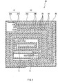
- Fig. 1 shows an exploded view of a secondary battery using the high molecular weight electrolyte according to this embodiment.
- This secondary battery has a construction, in which a battery device 20 on which a cathode terminal 11 and an anode terminal 12 are attached is enclosed inside film exterior members 30A and 30B.
- the cathode terminal 11 and the anode terminal 12 are directed from inside to outside of the exterior members 30A and 30B, and, for example, are derived in the same direction, respectively.
- the cathode terminal 11 and the anode terminal 12 are respectively made of a metal material such as aluminum (Al), copper (Cu), nickel (Ni), and stainless.
- the exterior members 30A and 30B are made of a laminated film in the shape of a rectangle, in which, for example, a nylon film, an aluminum foil, and a polyethylene film are bonded together in this order.
- the exterior members 30A and 30B are, for example, arranged so that a polyethylene film side and the battery device 20 are opposed, and respective outer edge parts are contacted to each other by fusion bonding or an adhesive.
- Adhesive films 31 to protect from outside air intrusion are inserted between the exterior members 30A, 30B and the cathode terminal 11, the anode terminal 12.
- the adhesive film 31 is made of a material having contact characteristics to the cathode terminal 11 and the anode terminal 12.
- the adhesive film 31 is preferably made of a polyolefin resin such as polyethylene, polypropylene, modified polyethylene, and modified polypropylene.
- the exterior members 30A and 30B can be made of a laminated film having other structure, a high molecular weight film such as polypropylene, or a metal film, instead of the foregoing laminated film.
- Fig. 2 is a view showing a cross section structure taken along line I-I of the battery device 20 shown in Fig. 1.
- a cathode 21 and an anode 22 are located oppositely with a high molecular weight electrolyte 23 according to this embodiment and a separator 24 inbetween, and are wound.
- An outermost periphery part thereof is protected by a protective tape 25.
- the cathode 21 has, for example, a structure, in which a cathode active material layer 21B is provided on both faces or one face of a cathode current collector 21A having a pair of opposed faces. At one end of the cathode current collector 21A in the longitudinal direction, there is an exposed part on which no cathode active material layer 21B is provided. The cathode terminal 11 is attached on this exposed part.
- the cathode current collector 21A is made of, for example, a metal foil such as an aluminum foil, a nickel foil, and a stainless foil.
- the cathode active material layer 21B includes, for example, one or more cathode materials capable of inserting and extracting lithium (Li) as a cathode active material, and can include a conductive agent and a binder if necessary.
- a cathode material capable of inserting and extracting lithium for example, metal sulfides or metal oxides not containing lithium such as titanium sulfide (TiS 2 ), molybdenum sulfide (MoS 2 ), niobium selenide (NbSe 2 ), and vanadium oxide (V 2 O 5 ); lithium complex oxides containing lithium; lithium-containing phosphoric acid compounds; and high molecular weight compounds such as polyacetylene and polypyrrole can be cited.
- the lithium complex oxide and the lithium-containing phosphoric acid compound are preferable, since a high voltage and a high energy density can be thereby obtained.
- a material expressed by a chemical formula of Li x MIO 2 or a chemical formula of Li y MIIPO 4 can be cited.
- MI and MII represent one or more of transition metals, and in particular, preferably include at least one of cobalt (Co), nickel, manganese (Mn), and iron (Fe).
- Values of x and y vary according to charge and discharge conditions of the battery, and are generally in the range of 0.05 ⁇ x ⁇ 1.10, and 0.05 ⁇ y ⁇ 1.10.
- lithium complex oxides expressed by the chemical formula of Li x MIO 2 include lithium cobalt complex oxides (LiCoO 2 ), lithium nickel complex oxides (LiNiO 2 ), lithium nickel cobalt complex oxides (LiNi z Co 1-Z O 2 (0 ⁇ z ⁇ 1)), and lithium manganese complex oxides (LiMn 2 O 4 ).
- the anode 22 has a structure, in which an anode active material layer 22B is provided on both faces or one face of an anode current collector 22A having a pair of opposed faces.
- the anode current collector 22A is made of, for example, a metal foil such as a copper foil, a nickel foil, and a stainless foil.
- the anode active material layer 22B includes, for example, one or more of an anode material capable of inserting and extracting lithium and metal lithium, and can include a conductive agent and a binder if necessary.
- an anode material capable of inserting and extracting lithium for example, carbon materials, metal oxides, and high molecular weight compounds can be cited.
- carbon materials, metal oxides, and high molecular weight compounds can be cited.
- carbon material non-graphitizable carbon materials, graphite materials and the like can be cited. More specifically, pyrolytic carbons, cokes, graphites, glassy carbons, organic high molecular weight compound fired body, carbon fiber, activated carbon and the like can be cited.
- cokes include pitch coke, needle coke, and petroleum coke.
- the organic high molecular weight compound fired body is a material, which is carbonized by firing a high molecular weight material such as phenol resins and furan resins at appropriate temperatures.
- a metal oxide iron oxide, ruthenium oxide, molybdenum oxide and the like can be cited.
- polyacetylene, polypyrrole and the like can be cited.
- alloys include alloys consisting of two or more metal elements and, in addition, alloys consisting of one or more metal elements and one or more metalloid elements. Structures thereof include a solid solution structure, an eutectic (eutectic mixture) structure, an intermetallic compound structure, and a structure, in which two or more of the foregoing structures coexist.
- metal elements or metalloid elements include, for example, tin (Sn), lead (Pb), aluminum, indium (In), silicon (Si), zinc (Zn), antimony (Sb), bismuth (Bi), gallium (Ga), germanium (Ge), arsenic (As), silver (Ag), hafnium (Hf), zirconium (Zr), and yttrium (Y).
- alloys or compounds thereof include, for example, alloys or compounds which are expressed by a chemical formula of Ma s Mb t .
- Ma represents at least one of metal elements and metalloid elements capable of forming an alloy with lithium
- Mb represents at least one of elements other than Ma. Values of s and t are s>0 and t ⁇ 0, respectively.
- Such alloys and compounds include LiAl, AlSb, CuMgSb, SiB 4 , SiB 6 , Mg 2 Si, Mg 2 Sn, Ni 2 Si, TiSi 2 , MoSi 2 , CoSi 2 , NiSi 2 , CaSi 2 , CrSi 2 , Cu 5 Si, FeSi 2 , MnSi 2 , NbSi 2 , TaSi 2 , VSi 2 , WSi 2 , ZnSi 2 , SiC, Si 3 N 4 ) Si 2 N 2 O, SiO v (0 ⁇ v ⁇ 2), SnO w (0 ⁇ w ⁇ 2), SnSiO 3 , LiSiO, and LiSnO.
- the separator 24 is constructed from, for example, a porous film made of a polyolefin material such as polypropylene and polyethylene, or a porous film made of an inorganic material such as a ceramics nonwoven cloth. They are insulative thin films having large ion permeability and given mechanical strength.
- the separator 24 can have a structure, in which two or more of the foregoing porous films are layered.
- This secondary battery can be, for example, manufactured as follows.
- the cathode 21 is fabricated.
- the cathode active material when a particulate cathode active material is used, the cathode active material, and if necessary, a conductive agent, and a binder are mixed to prepare a cathode mixture.
- the cathode mixture is dispersed in a dispersion medium such as N-methyl-2-pyrrolidone to obtain a cathode mixture slurry.
- the cathode current collector 21A is coated with this cathode mixture slurry, dried, and compression-molded to form the cathode active material layer 21B.
- the anode 22 is fabricated.
- the anode active material when a particulate anode active material is used, the anode active material, and if necessary, a conductive agent, and a binder are mixed to prepare an anode mixture.
- the anode mixture is dispersed in a dispersion medium such as N-methyl-2-pyrrolidone to obtain an anode mixture slurry.
- the anode current collector 22A is coated with this anode mixture slurry, dried, and compression-molded to form the anode active material layer 22B.
- the cathode terminal 11 is attached on the cathode 21, and the anode terminal 12 is attached on the anode 22.
- the separator 24, the cathode 21, the separator 24, and the anode 22 are sequentially layered and wound.
- the protective tape 25 is adhered to the outermost periphery part to form the winding electrode body.
- this winding electrode body is sandwiched between the exterior members 30A and 30B, and outer edge parts except for one side of the exterior members 30A and 30B are thermally fusion-bonded to obtain a pouched state.
- the composition for electrolyte including the foregoing electrolytic solution, polymerizable compound, and if necessary, the polymerization initiator is prepared, which is injected through an opening of the exterior members 30A and 30B into inside the winding electrode body, and enclosed by thermal fusion bonding the opening of the exterior members 30A and 30B.
- the winding electrode body, into which the composition for electrolyte is injected is heated from outside the exterior members 30A and 30B to polymerize the polymerizable compound.
- the gelatinous high molecular weight electrolyte 23 is formed.
- heating temperatures are preferably 90°C or less, and are more preferably 75°C or less.
- the secondary battery shown in Figs. 1 and 2 is completed.
- This secondary battery may be manufactured as follows. For example, it is possible that the composition for electrolyte is not injected after fabricating the winding electrode body, but the cathode 21 and the anode 22 are coated with the composition for electrolyte, and then the resultant is wound, enclosed inside the exterior members 30A and 30B, and heated. Otherwise, it is possible that the cathode 21 and the anode 22 are coated with the composition for electrolyte, the resultant is heated to form the high molecular weight electrolyte 23, and then the resultant is wound and enclosed inside the exterior members 30A and 30B. However, it is more preferable that heating is performed after enclosing the resultant inside the exterior members 30A and 30B.
- lithium ions when charged, for example, lithium ions are extracted from the cathode active material layer 21B, and inserted in the anode active material layer 22B through the high molecular weight electrolyte 23.
- lithium ions When discharged, for example, lithium ions are extracted from the anode active material layer 22B, and are inserted in the cathode active material layer 21B through the high molecular weight electrolyte 23.
- the high molecular weight electrolyte 23 includes the compound having P-O-Si bond or B-O-Si bond, the unreacted polymerizable compound or the polymerization initiator are inhibited from reacting in the electrode.
- the high molecular weight electrolyte 23 obtained by heating the composition for electrolyte of this embodiment since the high molecular weight electrolyte 23 includes the compound having P-O-Si bond or B-O-Si bond, for example, in the case of being used for the battery of this embodiment, the unreacted polymerizable compound, the polymerization initiator and the like can be inhibited from reacting in the electrode, increase in resistance can be inhibited, and lowering of the capacity can be inhibited.
- the content of the compound having P-O-Si bond or B-O-Si bond in the electrolytic solution is in the range from 0.1 wt% to 5 wt%, higher effects can be obtained.
- the compound having an acrylate group or a methacrylate group, and not including an ether group is used, in particular, the compound having the respective structures expressed by Chemical formulas 8, 9, and 10 is used, battery characteristics such as a capacity and cycle characteristics can be further improved.
- lithium carbonate (Li 2 CO 3 ) and 1 mol of cobalt carbonate (CoCo 3 ) were mixed, and the mixture was fired for 5 hours at 900°C in the air to obtain lithium cobalt complex oxide (LiCoO 2 ) as a cathode active material.
- LiCoO 2 lithium cobalt complex oxide
- 85 parts by mass of the obtained lithium cobalt complex oxide, 5 parts by mass of graphite as a conductive agent, and 10 parts by mass of polyvinylidene fluoride as a binder were mixed to prepare a cathode mixture.
- the cathode mixture was dispersed in N-methyl-2-pyrrolidone, which is a dispersion medium, to obtain a cathode mixture slurry.
- both faces of the cathode current collector 21A made of an aluminum foil being 20 ⁇ m thick were uniformly coated with this cathode mixture slurry, dried, and compression-molded by a roll pressing machine to form the cathode active material layer 21B. Consequently, the cathode 21 was fabricated. After that, the cathode terminal 11 was attached on the cathode 21.
- pulverized graphite powders were prepared as an anode active material. 90 parts by mass of the graphite powders and 10 parts by mass of polyvinylidene fluoride as a binder were mixed to prepare an anode mixture. The anode mixture was dispersed in N-methyl-2-pyrrolidone, which is a dispersion medium, to obtain an anode mixture slurry. Next, both faces of the anode current collector 22A made of a copper foil being 15 ⁇ m thick were uniformly coated with this anode mixture slurry, dried, and compression-molded by a roll pressing machine to form the anode active material layer 22B. Consequently, the anode 22 was fabricated. Subsequently, the anode terminal 12 was attached on the anode 22.
- the cathode 21 and the anode 22 were fabricated, the cathode 21 and the anode 22 were contacted with the separator 24 made of a micro-porous polyethylene film being 25 ⁇ m thick inbetween, wound in the longitudinal direction, and the protective tape 25 was adhered to the outermost periphery part. Thereby, the winding electrode was fabricated.
- an electrolytic solution 100 parts by mass of an electrolytic solution, 5 parts by mass of a polymerizable compound solution, and 0.1 parts by mass of t-butyl peroxyneodecanoate as a peroxyester polymerization initiator were mixed to prepare a composition for electrolyte.
- tris (trimethylsilyl) phosphate expressed by Chemical formula 4 was used in Example 1
- tris (triethylsilyl) phosphate expressed by Chemical formula 5 was used in Example 2
- tris (trimethylsilyl) borate expressed by Chemical formula 6 was used in Example 3.
- a content of all the additive in the electrolytic solution was 1 wt%.
- the fabricated winding electrode body was loaded between the exterior members 30A and 30B, and three sides of the exterior members 30A and 30B were thermally fusion-bonded.
- a dampproof aluminum laminated film in which a nylon film being 25 ⁇ m thick, an aluminum foil being 40 ⁇ m thick, and a polypropylene film being 30 ⁇ m thick were sequentially layered from the outermost layer was used.
- the composition for electrolyte was injected inside the exterior members 30A and 30B, the remaining one side of the exterior members 30A and 30B was thermally fusion-bonded under the reduced pressure, and hermetically sealed. After that, the resultant was sandwiched between glass plates, heated for 15 minutes at 70 °C to polymerize the polymerizable compound. Thereby, the composition for electrolyte was gelated to obtain the high molecular weight electrolyte 23. Thereby, the secondary battery shown in Figs. 1 and 2 was obtained.
- Comparative example 1 a secondary battery was fabricated as in Example 1, except that the additive was not used; in Comparative example 2, the secondary battery was fabricated as in Example 1, except that the polymerizable compound solution and the polymerization initiator were not used, and heating treatment was not performed; and in Comparative example 3, the secondary battery was fabricated as in Example 1, except that the polymerizable compound solution, the polymerization initiator, and the additive were not used, and heating treatment was not performed.
- a resistance increase ratio before and after storage was calculated by [(resistance after storage - resistance before storage)/resistance before storage] ⁇ 100. Further, a discharge capacity retention ratio at low temperatures was calculated by (discharge capacity after storage/discharge capacity before storage) ⁇ 100.
- Example 2 Secondary batteries were fabricated as in Example 1, except that contents of tris (trimethylsilyl) phosphate in the electrolytic solution were changed as shown in Table 2. Regarding these secondary batteries, resistance increase ratios and discharge capacity retention ratios before and after storage were obtained similarly to in Example 1. Results thereof are shown in Table 2 together with the results of Example 1 and Comparative example 1. Content of additive (tris (trimethylsilyl) phosphate) (wt°/) Resistance increase ratio (%) Discharge capacity retention ratio (%) Example 4 0.05 +20% 83% Example 5 0.1 +13% 90% Example 1 1 +10% 93% Example 6 5 +12% 91% Example 7 6 +15% 86% Comparative example 1 0 +29% 80%
- Example 2 results similar to in Example 1 were obtained. Further, according to Examples 1, 5, and 6, improvement effects of the charge capacity retention ratio were larger than in Example 4, in which the content of the additive was less than 0.1 wt%, or in Example 7, in which the content of the additive was over 5 wt%. That is, when the content of the compound having P-O-Si bond or B-O-Si bond in the electrolytic solution is from 0.1 wt% to 5 wt%, increase in battery resistance can be more inhibited, and lowering of the capacity can be more inhibited.
- the composition for electrolyte includes the electrolytic solution, the polymerizable compound, and if necessary, the polymerization initiator has been described.
- the composition for electrolyte can include other materials, additives and the like.
- the composition for electrolyte is heated to fabricate the high molecular weight electrolyte 23.
- the composition for electrolyte can be heated while being pressurized, or can be pressurized after being heated.
- the construction of the secondary battery has been described with reference to one example.
- the invention can be applied to batteries having other construction.
- the invention can be similarly applied to a monolayer laminated type secondary battery, or a multilayer laminated type secondary battery.
- the invention can be applied to secondary batteries such as a so-called cylinder type, square type, coin type, button type and the like. Further, the invention is not only applied to the secondary batteries, but also applied to primary batteries.
- the secondary battery using lithium as an electrode reaction substance has been described.
- the invention can be applied to the case, in which as an electrode reaction substance, other alkali metal such as sodium and potassium, or an alkali earth metal such as magnesium and calcium, or other light metal such as aluminum is used.
- the cathode active material, the anode active material, the nonaqueous solvent and the like are selected according to the electrolyte salt.
Landscapes
- Chemical & Material Sciences (AREA)
- Engineering & Computer Science (AREA)
- Manufacturing & Machinery (AREA)
- General Chemical & Material Sciences (AREA)
- Electrochemistry (AREA)
- Physics & Mathematics (AREA)
- Chemical Kinetics & Catalysis (AREA)
- General Physics & Mathematics (AREA)
- Inorganic Chemistry (AREA)
- Condensed Matter Physics & Semiconductors (AREA)
- Dispersion Chemistry (AREA)
- Civil Engineering (AREA)
- Structural Engineering (AREA)
- Spectroscopy & Molecular Physics (AREA)
- Mechanical Engineering (AREA)
- Secondary Cells (AREA)
Applications Claiming Priority (2)
| Application Number | Priority Date | Filing Date | Title |
|---|---|---|---|
| JP2004105653A JP2005293962A (ja) | 2004-03-31 | 2004-03-31 | 電解質用組成物、高分子電解質およびそれを用いた電池 |
| JP2004105653 | 2004-03-31 |
Publications (1)
| Publication Number | Publication Date |
|---|---|
| EP1585142A1 true EP1585142A1 (de) | 2005-10-12 |
Family
ID=34909450
Family Applications (1)
| Application Number | Title | Priority Date | Filing Date |
|---|---|---|---|
| EP05006915A Withdrawn EP1585142A1 (de) | 2004-03-31 | 2005-03-30 | Elektrolytzusammensetzung, Elektrolyt mit hohem Molekularbgewicht und dieses enthaltende Batterien. |
Country Status (6)
| Country | Link |
|---|---|
| US (1) | US20050221195A1 (de) |
| EP (1) | EP1585142A1 (de) |
| JP (1) | JP2005293962A (de) |
| KR (1) | KR20060044982A (de) |
| CN (1) | CN1840550A (de) |
| TW (1) | TWI279935B (de) |
Cited By (3)
| Publication number | Priority date | Publication date | Assignee | Title |
|---|---|---|---|---|
| EP1926172A1 (de) * | 2006-11-20 | 2008-05-28 | Samsung SDI Co., Ltd. | Elektrolyt für eine wiederaufladbare Lithiumbatterie und wiederaufladbare Lithiumbatterie damit |
| EP2219258A1 (de) * | 2009-01-22 | 2010-08-18 | Samsung SDI Co., Ltd. | Elektrolyt für wiederaufladbare Lithiumbatterie und wiederaufladbare Lithiumbatterie denselben enthaltend |
| WO2018021746A1 (ko) * | 2016-07-25 | 2018-02-01 | 삼성에스디아이주식회사 | 리튬 전지 전해질용 첨가제, 이를 포함하는 리튬 전지용 전해질 및 상기 전해질을 채용한 리튬 전지 |
Families Citing this family (22)
| Publication number | Priority date | Publication date | Assignee | Title |
|---|---|---|---|---|
| KR100745732B1 (ko) * | 2005-06-14 | 2007-08-02 | 삼성에스디아이 주식회사 | 유기 전해액 및 이를 채용한 리튬 전지 |
| KR100873632B1 (ko) * | 2005-08-24 | 2008-12-12 | 삼성에스디아이 주식회사 | 유기전해액 및 이를 채용한 리튬 전지 |
| KR101340031B1 (ko) | 2007-03-23 | 2013-12-10 | 삼성에스디아이 주식회사 | 리튬 이차 전지용 전해액 및 이를 포함하는 리튬 이차 전지 |
| US7732546B2 (en) * | 2007-10-03 | 2010-06-08 | Bausch & Lomb Incorporated | Use of silylated sulfonate monomers to improve contact lens wettability |
| US20110136018A1 (en) * | 2008-08-06 | 2011-06-09 | Mitsui Chemicals, Inc. | Non-aqueous electrolytic solution, lithium secondary battery and method for producing same, and mixed-type non-aqueous electrolytic solution |
| JP5598867B2 (ja) * | 2009-02-26 | 2014-10-01 | エルジー・ケム・リミテッド | リチウム二次電池用非水電解質及びそれを備えたリチウム二次電池 |
| JP5487297B2 (ja) * | 2010-04-06 | 2014-05-07 | 株式会社東芝 | 非水電解質電池 |
| JP5427101B2 (ja) * | 2010-04-27 | 2014-02-26 | 株式会社日立製作所 | 非水電解液及びそれを用いた非水電解液二次電池 |
| JP5664773B2 (ja) * | 2011-05-19 | 2015-02-04 | トヨタ自動車株式会社 | リチウム固体電池 |
| KR101537142B1 (ko) * | 2012-04-30 | 2015-07-15 | 주식회사 엘지화학 | 전해액 첨가제, 상기 첨가제를 포함하는 비수성 전해액 및 리튬 이차 전지 |
| KR101994262B1 (ko) * | 2012-11-09 | 2019-06-28 | 삼성에스디아이 주식회사 | 리튬 이차 전지용 전해질 및 이를 포함하는 리튬 이차 전지 |
| EP2908375B1 (de) | 2013-10-28 | 2018-09-19 | LG Chem, Ltd. | Lithiumsekundärbatterie |
| KR102310478B1 (ko) * | 2014-09-16 | 2021-10-08 | 에스케이이노베이션 주식회사 | 리튬 이차전지 전해액 및 이를 포함하는 리튬 이차전지 |
| CN106033824B (zh) * | 2015-03-18 | 2018-12-04 | 宁德时代新能源科技股份有限公司 | 高电压锂离子电池及其电解液 |
| JP2016189327A (ja) * | 2015-03-27 | 2016-11-04 | 旭化成株式会社 | 非水蓄電デバイス用電解液の添加剤 |
| CN104701571B (zh) * | 2015-03-30 | 2018-04-10 | 中国科学院福建物质结构研究所 | 一种锂离子电池用耐高温耐高压电解液 |
| HUE060241T2 (hu) * | 2016-07-22 | 2023-02-28 | Daikin Ind Ltd | Elektrolitoldat, elektrokémiai eszköz, másodlagos akkumulátor és modul |
| US11322780B2 (en) | 2016-07-22 | 2022-05-03 | Daikin Industries, Ltd. | Electrolyte solution, electrochemical device, secondary battery, and module |
| CN107634261B (zh) * | 2017-08-18 | 2019-12-13 | 清华大学 | 一种用于聚合物电池的聚合物电解质及其制备方法 |
| CN109786824B (zh) | 2019-01-25 | 2021-09-24 | 宁德新能源科技有限公司 | 电解液和使用其的电化学装置 |
| CN109802180B (zh) | 2019-01-25 | 2021-08-03 | 宁德新能源科技有限公司 | 电解液及电化学装置 |
| CN113451649B (zh) * | 2020-03-27 | 2025-01-21 | 河北圣泰材料股份有限公司 | 硼酸锂类化合物于电池电解液中的应用 |
Citations (1)
| Publication number | Priority date | Publication date | Assignee | Title |
|---|---|---|---|---|
| US6562513B1 (en) * | 1998-09-17 | 2003-05-13 | Showa Denki Kabushiki Kaisha | Thermopolymerizable composition for battery use |
-
2004
- 2004-03-31 JP JP2004105653A patent/JP2005293962A/ja not_active Abandoned
-
2005
- 2005-03-21 US US11/084,956 patent/US20050221195A1/en not_active Abandoned
- 2005-03-22 TW TW094108785A patent/TWI279935B/zh not_active IP Right Cessation
- 2005-03-30 EP EP05006915A patent/EP1585142A1/de not_active Withdrawn
- 2005-03-30 KR KR1020050026360A patent/KR20060044982A/ko not_active Withdrawn
- 2005-03-31 CN CNA2005100697346A patent/CN1840550A/zh active Pending
Patent Citations (1)
| Publication number | Priority date | Publication date | Assignee | Title |
|---|---|---|---|---|
| US6562513B1 (en) * | 1998-09-17 | 2003-05-13 | Showa Denki Kabushiki Kaisha | Thermopolymerizable composition for battery use |
Cited By (6)
| Publication number | Priority date | Publication date | Assignee | Title |
|---|---|---|---|---|
| EP1926172A1 (de) * | 2006-11-20 | 2008-05-28 | Samsung SDI Co., Ltd. | Elektrolyt für eine wiederaufladbare Lithiumbatterie und wiederaufladbare Lithiumbatterie damit |
| US7494746B2 (en) | 2006-11-20 | 2009-02-24 | Samsung Sdi Co., Ltd. | Electrolyte for rechargeable lithium battery, and rechargeable lithium battery including same |
| EP2219258A1 (de) * | 2009-01-22 | 2010-08-18 | Samsung SDI Co., Ltd. | Elektrolyt für wiederaufladbare Lithiumbatterie und wiederaufladbare Lithiumbatterie denselben enthaltend |
| US8945776B2 (en) | 2009-01-22 | 2015-02-03 | Samsung Sdi Co., Ltd. | Electrolyte for rechargeable lithium battery and rechargeable lithium battery including the same |
| WO2018021746A1 (ko) * | 2016-07-25 | 2018-02-01 | 삼성에스디아이주식회사 | 리튬 전지 전해질용 첨가제, 이를 포함하는 리튬 전지용 전해질 및 상기 전해질을 채용한 리튬 전지 |
| US11031627B2 (en) | 2016-07-25 | 2021-06-08 | Samsung Sdi Co., Ltd. | Additive for electrolyte of lithium battery, electrolyte for lithium battery including same, and lithium battery employing same electrolyte |
Also Published As
| Publication number | Publication date |
|---|---|
| CN1840550A (zh) | 2006-10-04 |
| TWI279935B (en) | 2007-04-21 |
| JP2005293962A (ja) | 2005-10-20 |
| KR20060044982A (ko) | 2006-05-16 |
| US20050221195A1 (en) | 2005-10-06 |
| TW200605424A (en) | 2006-02-01 |
Similar Documents
| Publication | Publication Date | Title |
|---|---|---|
| US20050221195A1 (en) | Composition for electrolyte, high molecular weight electrolyte, and battery using it | |
| US7718314B2 (en) | Cathode material and battery | |
| US20070224510A1 (en) | Anode and battery | |
| US20060019170A1 (en) | Battery | |
| KR101047270B1 (ko) | 전지 | |
| JPWO2006088002A1 (ja) | 電解液および電池 | |
| US7074522B2 (en) | Battery | |
| US7919208B2 (en) | Anode active material and battery | |
| JP4013036B2 (ja) | 電池およびその製造方法 | |
| KR101315549B1 (ko) | 고분자 전해질 및 그것을 이용한 전지 | |
| CN100568608C (zh) | 聚合物电解质和电池 | |
| US8216724B2 (en) | Polymer electrolyte and battery | |
| JP4609707B2 (ja) | 電池 | |
| JP2006059710A (ja) | 電解質および電池 | |
| JP2004311114A (ja) | 電解質用組成物、高分子電解質およびそれを用いた電池 | |
| JP2006253086A (ja) | 高分子電解質、電池および電池の製造方法 | |
| JP2004342376A (ja) | 電池の製造方法 | |
| JP2004311140A (ja) | 電解質用組成物、高分子電解質およびそれを用いた電池 | |
| JP2004139823A (ja) | 電解質用組成物、高分子電解質およびそれを用いた電池 | |
| JP2004311115A (ja) | 電解質用組成物、高分子電解質およびそれを用いた電池 | |
| JP2008066004A (ja) | 非水電解質組成物及び非水電解質二次電池 | |
| JP4117674B2 (ja) | 電池の製造方法および電池 | |
| JP5195838B2 (ja) | 電池の製造方法 | |
| JP2007141494A (ja) | 電解質,負極および電池 | |
| JP2007123099A (ja) | 高分子電解質、電池およびそれらの製造方法 |
Legal Events
| Date | Code | Title | Description |
|---|---|---|---|
| PUAI | Public reference made under article 153(3) epc to a published international application that has entered the european phase |
Free format text: ORIGINAL CODE: 0009012 |
|
| AK | Designated contracting states |
Kind code of ref document: A1 Designated state(s): AT BE BG CH CY CZ DE DK EE ES FI FR GB GR HU IE IS IT LI LT LU MC NL PL PT RO SE SI SK TR |
|
| AX | Request for extension of the european patent |
Extension state: AL BA HR LV MK YU |
|
| 17P | Request for examination filed |
Effective date: 20060130 |
|
| AKX | Designation fees paid |
Designated state(s): DE FR GB |
|
| STAA | Information on the status of an ep patent application or granted ep patent |
Free format text: STATUS: THE APPLICATION HAS BEEN WITHDRAWN |
|
| 18W | Application withdrawn |
Effective date: 20071121 |