EP1583620B1 - Verfahren zum ausformen eines blechdeckels - Google Patents
Verfahren zum ausformen eines blechdeckels Download PDFInfo
- Publication number
- EP1583620B1 EP1583620B1 EP03808249A EP03808249A EP1583620B1 EP 1583620 B1 EP1583620 B1 EP 1583620B1 EP 03808249 A EP03808249 A EP 03808249A EP 03808249 A EP03808249 A EP 03808249A EP 1583620 B1 EP1583620 B1 EP 1583620B1
- Authority
- EP
- European Patent Office
- Prior art keywords
- projection
- panel
- preform
- score
- postforming
- Prior art date
- Legal status (The legal status is an assumption and is not a legal conclusion. Google has not performed a legal analysis and makes no representation as to the accuracy of the status listed.)
- Expired - Lifetime
Links
- 238000000034 method Methods 0.000 title claims abstract description 18
- 239000002184 metal Substances 0.000 title claims description 20
- 230000008569 process Effects 0.000 claims abstract description 6
- 238000004049 embossing Methods 0.000 claims description 4
- 238000002407 reforming Methods 0.000 claims description 3
- 238000011144 upstream manufacturing Methods 0.000 claims 2
- 230000000903 blocking effect Effects 0.000 abstract description 4
- 238000007493 shaping process Methods 0.000 abstract 1
- 239000011324 bead Substances 0.000 description 13
- 230000015572 biosynthetic process Effects 0.000 description 7
- 238000004519 manufacturing process Methods 0.000 description 5
- 230000003313 weakening effect Effects 0.000 description 4
- 230000009466 transformation Effects 0.000 description 3
- 238000013461 design Methods 0.000 description 2
- 238000007711 solidification Methods 0.000 description 2
- 230000008023 solidification Effects 0.000 description 2
- 238000012549 training Methods 0.000 description 2
- 238000000844 transformation Methods 0.000 description 2
- KJLPSBMDOIVXSN-UHFFFAOYSA-N 4-[4-[2-[4-(3,4-dicarboxyphenoxy)phenyl]propan-2-yl]phenoxy]phthalic acid Chemical compound C=1C=C(OC=2C=C(C(C(O)=O)=CC=2)C(O)=O)C=CC=1C(C)(C)C(C=C1)=CC=C1OC1=CC=C(C(O)=O)C(C(O)=O)=C1 KJLPSBMDOIVXSN-UHFFFAOYSA-N 0.000 description 1
- 230000009471 action Effects 0.000 description 1
- 230000001174 ascending effect Effects 0.000 description 1
- 230000004888 barrier function Effects 0.000 description 1
- 238000005452 bending Methods 0.000 description 1
- 235000013361 beverage Nutrition 0.000 description 1
- 238000004891 communication Methods 0.000 description 1
- 238000005056 compaction Methods 0.000 description 1
- 238000011161 development Methods 0.000 description 1
- 230000000694 effects Effects 0.000 description 1
- 230000002349 favourable effect Effects 0.000 description 1
- 230000006872 improvement Effects 0.000 description 1
- 238000010348 incorporation Methods 0.000 description 1
- 238000003780 insertion Methods 0.000 description 1
- 230000037431 insertion Effects 0.000 description 1
- 230000000670 limiting effect Effects 0.000 description 1
- 239000002243 precursor Substances 0.000 description 1
- 230000002265 prevention Effects 0.000 description 1
- 238000012545 processing Methods 0.000 description 1
- 230000009467 reduction Effects 0.000 description 1
- 230000000630 rising effect Effects 0.000 description 1
- 239000013589 supplement Substances 0.000 description 1
- 230000007704 transition Effects 0.000 description 1
Images

Classifications
-
- B—PERFORMING OPERATIONS; TRANSPORTING
- B21—MECHANICAL METAL-WORKING WITHOUT ESSENTIALLY REMOVING MATERIAL; PUNCHING METAL
- B21D—WORKING OR PROCESSING OF SHEET METAL OR METAL TUBES, RODS OR PROFILES WITHOUT ESSENTIALLY REMOVING MATERIAL; PUNCHING METAL
- B21D51/00—Making hollow objects
- B21D51/16—Making hollow objects characterised by the use of the objects
- B21D51/38—Making inlet or outlet arrangements of cans, tins, baths, bottles, or other vessels; Making can ends; Making closures
- B21D51/383—Making inlet or outlet arrangements of cans, tins, baths, bottles, or other vessels; Making can ends; Making closures scoring lines, tear strips or pulling tabs
-
- B—PERFORMING OPERATIONS; TRANSPORTING
- B65—CONVEYING; PACKING; STORING; HANDLING THIN OR FILAMENTARY MATERIAL
- B65D—CONTAINERS FOR STORAGE OR TRANSPORT OF ARTICLES OR MATERIALS, e.g. BAGS, BARRELS, BOTTLES, BOXES, CANS, CARTONS, CRATES, DRUMS, JARS, TANKS, HOPPERS, FORWARDING CONTAINERS; ACCESSORIES, CLOSURES, OR FITTINGS THEREFOR; PACKAGING ELEMENTS; PACKAGES
- B65D17/00—Rigid or semi-rigid containers specially constructed to be opened by cutting or piercing, or by tearing of frangible members or portions
- B65D17/28—Rigid or semi-rigid containers specially constructed to be opened by cutting or piercing, or by tearing of frangible members or portions at lines or points of weakness
- B65D17/401—Rigid or semi-rigid containers specially constructed to be opened by cutting or piercing, or by tearing of frangible members or portions at lines or points of weakness characterised by having the line of weakness provided in an end wall
- B65D17/4012—Rigid or semi-rigid containers specially constructed to be opened by cutting or piercing, or by tearing of frangible members or portions at lines or points of weakness characterised by having the line of weakness provided in an end wall for opening partially by means of a tearing tab
-
- B—PERFORMING OPERATIONS; TRANSPORTING
- B65—CONVEYING; PACKING; STORING; HANDLING THIN OR FILAMENTARY MATERIAL
- B65D—CONTAINERS FOR STORAGE OR TRANSPORT OF ARTICLES OR MATERIALS, e.g. BAGS, BARRELS, BOTTLES, BOXES, CANS, CARTONS, CRATES, DRUMS, JARS, TANKS, HOPPERS, FORWARDING CONTAINERS; ACCESSORIES, CLOSURES, OR FITTINGS THEREFOR; PACKAGING ELEMENTS; PACKAGES
- B65D2517/00—Containers specially constructed to be opened by cutting, piercing or tearing of wall portions, e.g. preserving cans or tins
- B65D2517/0001—Details
- B65D2517/001—Action for opening container
- B65D2517/0014—Action for opening container pivot tab and push-down tear panel
-
- B—PERFORMING OPERATIONS; TRANSPORTING
- B65—CONVEYING; PACKING; STORING; HANDLING THIN OR FILAMENTARY MATERIAL
- B65D—CONTAINERS FOR STORAGE OR TRANSPORT OF ARTICLES OR MATERIALS, e.g. BAGS, BARRELS, BOTTLES, BOXES, CANS, CARTONS, CRATES, DRUMS, JARS, TANKS, HOPPERS, FORWARDING CONTAINERS; ACCESSORIES, CLOSURES, OR FITTINGS THEREFOR; PACKAGING ELEMENTS; PACKAGES
- B65D2517/00—Containers specially constructed to be opened by cutting, piercing or tearing of wall portions, e.g. preserving cans or tins
- B65D2517/0001—Details
- B65D2517/0058—Other details of container end panel
- B65D2517/0068—Ribs or projections in container end panel
- B65D2517/0071—Ribs or projections in container end panel located externally of tear-out/push-in panel or preformed opening
Definitions
- the invention is concerned with a further improvement or further development of the position fixation of a grip tab on a metal lid according to the coparticulated co-pending PCT application, which is the same inventor and assignee, the disclosure of which is incorporated herein by reference.
- the invention faces the technical problem of achieving a similar effect, but to improve the production and reliability of the turnstile or a positional alignment of the mounted grip tab. For this purpose, a method should be proposed.
- the already existing marginal edge is used on a conventional grip tab, which does not have to be specifically designed in addition to obtain the turnstile after attaching the grip tab on the panel ("staking").
- the only influence takes place on the metal lid itself, which receives a shape, as it is the rivet in the pre-stage, which preferably preformed during the formation of the rivet in parallel with and later formed in a further operation of the resulting sheet metal lid or formed more accurate (“reformed ”) can (claim 1).
- the projection can thus be formed integrally with the sheet metal lid, as it is also the attachment point by integral formation for the attachment tab (the attachment portion) of the grip tab.
- the protrusion does not protrude through an opening of the attachment portion, and the attachment portion is not previously provided with an opening, but the attachment portion remains intact, and a barrier externally applied to the attachment portion is provided.
- At least one unbalanced in cross-section projection which is formed steeper at its flank pointing to the mounting portion than the flank remote there (there claim 17, 18, 19 and 23 or 24 of the co-filed WO application).
- Such a design can also be selected with punctiform or oval projections.
- the post-deformation is preferably a reduction in thickness of a top of the (strip-shaped) projection (here claim 3 or 4). This results in solidification of this portion and the entire projection as such as well. This also concerns the procedure.
- the score line can also be inserted, in staggered steps. The same applies to the preforming of the bead, which is not formed at the same time as the score line is introduced (claim 1, claim 5).
- the blocking effect which may also be a limiting effect, that is, to be understood as a complete prevention of rotational movement to a significant restriction of rotational movement, there is a striking an outer edge of the flat mounting portion (rivet island) on the molded from the sheet metal lid Head Start.
- the projection may be strip-shaped (line-shaped) and preferably oriented transversely and / or parallel to a longitudinal extension of the grip tab (longitudinal axis or longitudinal plane), wherein it engages on a correspondingly aligned edge edge of the attachment portion for its blocking effect or is formed very closely adjacent , In a longitudinal extent, the projection may extend over more than 30%, preferably over more than 50% to more than 80% of the width of the attachment lug.
- the provision of a plurality of projections is possible, wherein not all projections must be assigned to the same outer edge portion of the mounting portion.
- the projections can also be designed differently, so strip-shaped, round to oval or combined. If a straight-line outer edge section of the attachment section is provided, a straight-line (strip-shaped) projection configuration can be advantageous.
- the linear strip design can also be achieved by juxtaposing at least two punctiform projections, which then form a group which is assigned to the same outer edge of the attachment section.
- a plurality of projections provided in the aforementioned sense, they need not attack on the same edge line of the attachment portion at the beginning of a rotational movement, but may be associated with different marginal edges. If a strip shape is provided as a projection, it can be made larger in its length than the diameter of the finished rivet head.
- the attachment portion is formed from one piece of the center region of the grip tab, there are only slight visible gaps between the mounted over a double fold line down to a lower level mounting portion and the slightly above parallel plane of the remaining grip tab.
- the attachment of the projections on at least one of the free, from the attachment portion facing outward marginal edges is therefore difficult or difficult to see from the outside, so that the rotation block is almost invisible to the viewer.
- a possibly color-coded grip tab is not changed further in its colored form.
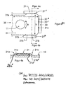
- Figures 4 / 4a are included here for the sake of clarity. Some reference numbers refer to this.
- the sheet-metal lid which is produced here in the method of FIGS . 1a to 3a can be seen to have a marginal portion 12 as a folded edge, which is suitable for folding onto a beverage can body.
- the sheet metal lid itself is made of a sheet of small thickness, usually below 0.24 mm, and has already preceding Workstations go through before Figure 1a shows him. It has an inner lid mirror (panel) 10, which is surrounded by the seam edge 12. Within the lid 10, a line of weakness 16 is to be introduced around an opening area which is surrounded by a substantially U-shaped bead 18.
- a substantially oval weakening line 16 should be designed as a score which has a transition portion which is not notched and thus serves as a connecting portion to the remaining panel 10 when an opening portion is broken through the action of a later mentioned grip tab along the score line 16. This is illustrated in FIG. 2a.
- an attachment point 11 is provided, which can be seen more clearly in the detail enlargements of the co-filed WO application. It is assigned a mounting portion as a sheet metal tabs 31 schematically, which is part of the grip tab of Figure 3 of the co-filed WO application, where it is integrally formed via a joint line as a bending line 38.
- This grip tab has a handle portion, here provided with a circular opening at which the grip tab is actuated by the user, for breaking the score line 16 of Figure 2a.
- the gripping tab also has, in front of the attachment section 31, an opening nose which is located as a nose for breaking over the opening section 17, for which purpose in FIG.
- an additional bead 18a is provided in one step, which reinforces the transverse LOE opening area by the opening forces to be able to apply to the burglary starting section (loop-shaped end of the score line 16).
- the arranged gripping tab lies substantially parallel to the panel, which itself need not be formed exactly in one plane, but may be slightly curved, but the area around the attachment point 11 is substantially planar and allows a substantially parallel arrangement of the attachment portion 31 the pull tab.
- At least one, preferably three strip-shaped projections 20 are formed as beads projecting upwards about this attachment point 11 (ie, to the outside of the sheet metal cover).
- the bead 20 lying transversely to the center plane 100 is longer than the two adjacent beads, which run parallel to the center plane 100. They are illustrated in FIGS. 3 and 4 of the co-filed WO application 21 a, 21 b, in which the longer bead 20 is shown more precisely in relation to the attachment tab 31 (FIG. 4 is also applicable here).
- the formation of the three beads 20 is improved or made more accurate.
- This "reforming” leads to a Forming the beads (protrusions), as used later for the positional fixing of Figure 3 and the remaining figures of the co-filed WO application.
- the at least one projection receives its correct profile geometry after at least one piece has been molded out of the cover sheet (the panel) according to FIG. 1a .
- the reshaping involves sculpting the preform 20 * with a coining (embossing process) to flatten the surface more.
- the tool is used equally from above and from below for training. It can be recognized by the left in the rising edge of the preform 20 * recognizable slight kink of Figure 8a of the co-filed WO application in the lower final form again, which also shows how the sharp leading edge 20 "in the first flat ascending left slope of the formed wall 20 *, to the right of the transverse plane 101, the second slope of the wall is formed from below to above to form, starting approximately with the slope of the wall 20 *, a flat upper surface 20c that slopes smoothly in the region 20b in the rest of the cover plate 10 passes.
- the tab lies with its intermediate web between the left opening and the handle opening substantially above the transverse projection 20.
- the two openings of the tab are shown in Figure 3, an opening is formed by the formation of the attachment portion 31, which continues on the joint line 38 is in communication with the grip tab, while the opening for the engagement of a finger is specially formed.
- This opening is part of the handle portion 32, wherein the web lying between the two openings is slightly curved in said figure 8a, with a front edge, which was related to the free edge of the mounting portion 31 in the manufacture. A large part of the projection 20 is thus below the bridge and is hardly noticeable from the outside.
- the two-stage training in addition to the order of processing according to Figures 1 to 3 of the co-filed WO application also a modified order be made, so first introducing the at least one preform, as they are based on the preform 20 * of the upper Field of said figure 8a is explained, in a first operation, still without introduction of score or score lines (as lines of weakness), as the line of weakness 16 is one.
- the wall thickness on the top side of the projection is reduced by approximately 10% to 15%, with concomitant compaction and solidification of this area, which is achieved by the embossing process (the coining) from above and below is achieved equally.
Landscapes
- Engineering & Computer Science (AREA)
- Mechanical Engineering (AREA)
- Containers Opened By Tearing Frangible Portions (AREA)
- Wire Bonding (AREA)
- Connection Of Plates (AREA)
- Blow-Moulding Or Thermoforming Of Plastics Or The Like (AREA)
- Closures For Containers (AREA)
- Orthopedics, Nursing, And Contraception (AREA)
- Lining Or Joining Of Plastics Or The Like (AREA)
- Microscoopes, Condenser (AREA)
- Diaphragms For Electromechanical Transducers (AREA)
- Insulating Bodies (AREA)
Description
- Die Erfindung befasst sich mit einer weiteren Verbesserung oder noch weiteren Ausbildung der Lagefixierung einer Grifflasche an einem Blechdeckel nach der parallel eingereichten (co-pending) PCT-Anmeldung, die von denselben Erfindern und derselben Rechtsnachfolgerin stammen, welche Offenbarung hier einbezogen wird.
- Das Aktenzeichen der co-pending PCT-Anmeldung lautet PCT/DE03/04283 vom 23. Dezember 2003, veröffentlicht unter WO-A 2004/065034 vom 5. August 2004, im folgenden auch als co-filed WO benannt.
- Im angebrachten Zustand der Grifflasche an dem Blechdeckel spricht der Fachmann von einem SOT (Stay on Tab), der zum Öffnen eines Öffnungsbereiches im Deckelspiegel (zumeist "Panel" genannt) vorgesehen ist. Dazu wird mit einer vertikal orientierten Kippbewegung, angefasst an einem Griffende, die Grifflasche angehoben, um mit ihrem Öffnungsende den Öffnungsbereich entlang einer Schwächungslinie (zumeist score-line genannt) aufzubrechen.
- Besonderes bei großen Öffnungen (LOE, large opening ends) als Öffnungsbereich ergeben sich im Stand der Technik Schwierigkeiten, die Positionen der Grifflasche im am Blechdeckel angebrachten Zustand zu fixieren. Dazu sind bereits Vorschläge gemacht worden, bspw. aus der US-A 5,799,816 (Schubert). Dort wird eine Durchbrechung eines Anbringungs-Abschnitts der Grifflasche vorgeschlagen, welcher Anbringungsabschnitt zumeist "rivet island" genannt wird. Dieser Anbringungsabschnitt wird über einen ausgeformten Niet an dem Panel des Blechdeckels befestigt und übergreift dabei mit einer ausgebildeten Öffnung im Anbringungsabschnitt eine rund bis länglich ausgeformte Sicke, die auch nach dem Anbringen der Grifflasche eingeformt werden kann, vgl. dort Spalte 3, Zeilen 63-67, Spalte 5, Zeilen 37 bis 44, dortiger Anspruch 3 und die zugehörige grafische Darstellung in der dortigen Figur 2 und 4.
- Aus der US-A 3,868,918 (Smith) ist ein Blechdeckel dem Fachmann zugänglich, der einen aufwärts eingeprägten Haken aufweist, vgl. dort Abstract, letztes Drittel. Mit dieser hakenförmigen Ausbildung aus dem Deckelblech soll die Grifflasche gehalten werden, was in der dortigen Figur 4 veranschaulicht wird. Die Ausbildung einer solchen hakenförmigen Nase, die ein Übergreifen über den Griffabschnitt des Griffrings verursacht, ist in der dortigen Figurenfolge 5 bis 10 erläutert, wobei nach den dortigen Figuren 11 und 14 ein Haken mit dem übergreifenden Ende (dort 40) erst durch einen weiteren Prägevorgang ausgebildet wird. Eine Kerblinie ist dort ebenfalls zu sehen, aber der Zeitpunkt ihrer Einbringung bleibt in der genannten Schrift offen. Gleichwohl ist ein mehrstufiges Verfahren zur Ausformung des Hakens dort beschrieben, bestehend aus einem ersten Schritt (dort Figur 5), einem zweiten Schritt (dort Figur 6), einem weiteren zweiten Schritt (dort Figur 10) und einem dritten Schritt (dort Figur 11) sowie einem weiteren dritten Schritt (dort Figur 14). Aus der Anzahl der Schritte mag ermessen werden, welch umfangreiche Umformungen aus dem 1975 noch sehr starken Deckelblech dort vorgenommen werden, welche große Höhen ausgeformt werden und welch hakenförmiges Gebilde durch viele Vorstufen von Umformungen erst mit der letzten Umformung nach der dortigen Figur 14 erreicht wird. Mit diesem Haken wird eine vertikale Sperrung der Grifflasche gegen Anheben erhalten, was dort durch den Begriff "lock down hook" plakativ erläutert wird, vgl. dortige Spalte 5, Zeilen 19 bis 25 und dortige Spalte 3, Zeilen 10 bis 25.
- Die Erfindung steht vor der technischen Problemstellung, eine ebensolche Wirkung zu erzielen, aber die Fertigung und die Zuverlässigkeit der Drehsperre bzw. eine Lageausrichtung der montierten Grifflasche zu verbessern. Dazu soll ein Verfahren vorgeschlagen werden.
- Vorteilhaft wird die schon vorliegende Randkante an einer üblichen Grifflasche verwendet, die nicht spezifisch zusätzlich ausgebildet werden muss, um die Drehsperre nach einem Anbringen der Grifflasche am Panel ("staking") zu erhalten. Die einzige Beeinflussung findet am Blechdeckel selbst statt, der eine Ausformung erhält, wie sie der Niet im Vorstadium auch ist, die bevorzugt auch während der Ausbildung des Nietes parallel mit vorausgeformt und später in einem weiteren Arbeitsvorgang des entstehenden Blechdeckels umgeformt oder genauer ausgeformt ("reformed") werden kann (Anspruch 1). Der Vorsprung kann also einstückig mit dem Blechdeckel ausgebildet werden, wie es auch die Befestigungsstelle durch einstückige Ausbildung für den Anbringungslappen (dem Anbringungsabschnitt) der Grifflasche ist.
- Der Vorsprung ragt nicht durch eine Öffnung des Anbringungsabschnitts hindurch und der Anbringungsabschnitt wird nicht zuvor mit einer Öffnung versehen, sondern der Anbringungsabschnitt bleibt unversehrt und eine von außen auf den Anbringungsabschnitt einwirkende Sperre wird vorgesehen, vgl. die co-filed WO-Anmeldung, die hier einbezogen ist.
- Besonders günstig ist die Ausbildung zumindest eines im Querschnitt unsymmetrischen Vorsprungs, der an seiner zum Anbringungsabschnitt weisenden Flanke steiler ausgebildet ist als die davon entferntere Flanke (dort Anspruch 17, 18, 19 und 23 oder 24 der co-filed WO-Anmeldung). Eine solche Ausbildung kann auch bei punktförmigen oder ovalen Vorsprüngen gewählt werden.
- Bei dem Nachverformen erfolgt bevorzugt eine Dickenreduzierung einer Oberseite des (streifenförmigen) Vorsprungs (hier Anspruch 3 oder 4). Dadurch entsteht eine Verfestigung dieses Abschnitts und des gesamten Vorsprungs als solches ebenso. Das betrifft auch das Verfahren. Nicht zeitgleich mit dem Nachformen kann auch die Kerblinie eingebracht werden, in zeitlich versetzten Arbeitsgängen. Gleiches gilt für das Vorformen der Sicke, die nicht zu gleicher Zeit geformt wird wie die Kerblinie eingebracht wird (Anspruch 1, Anspruch 5).
- Um die Sperrwirkung zu erhalten, die auch eine Begrenzungswirkung sein kann, also von einer völligen Verhinderung einer Drehbewegung bis zu einer wesentlichen Einschränkung der Drehbewegung verstanden werden soll, gibt es ein Anschlagen eines Außenrandes des flächigen Anbringungsabschnitts (rivet island) an dem aus dem Blechdeckel ausgeformten Vorsprung.
- Der Vorsprung kann streifenförmig (linienförmig) ausgebildet sein und bevorzugt quer und/oder parallel zu einer Längserstreckung der Grifflasche (Längsachse bzw. Längsebene) orientiert sein, wobei er an einer entsprechend ausgerichteten Randkante des Anbringungsabschnitts für seine Sperrwirkung angreift oder ihr ganz eng benachbart ausgebildet ist. In einer Längserstreckung kann sich der Vorsprung über mehr als 30 %, bevorzugt über mehr als 50 % bis mehr als 80 % der Breite des Anbringungslappens erstrecken.
- Das Vorsehen mehrerer Vorsprünge ist möglich, wobei nicht alle Vorsprünge demselben Außenrandabschnitt des Befestigungs-Abschnitts zugeordnet sein müssen. Die Vorsprünge können auch unterschiedlich ausgestaltet sein, so streifenförmig, rund bis oval oder kombiniert. Ist ein geradliniger Außenrandabschnitt des Anbringungsabschnitts vorgesehen, kann eine geradlinige (streifenförmige) Vorsprunggestaltung vorteilhaft sein. Die geradlinige Streifengestaltung kann auch durch Aneinanderreihen von zumindest zwei punktförmigen Vorsprüngen erreicht werden, die dann eine Gruppe bilden, die demselben Außenrand des Anbringungsabschnitts zugeordnet ist.
- Sind mehrere Vorsprünge im vorgenannten Sinne vorgesehen, müssen sie nicht an derselben Randlinie des Anbringungsabschnitts bei Beginn einer Drehbewegung angreifen, sondern können unterschiedlichen Randkanten zugeordnet sein. Ist eine Streifenform als Vorsprung vorgesehen, kann sie in ihrer Länge größer als der Durchmesser des fertigen Nietkopfs ausgebildet werden.
- Nachdem der Anbringungsabschnitt aus einem Stück des Mittenbereichs der Grifflasche ausgebildet ist, bestehen nur geringe sichtbare Zwischenräume zwischen dem über eine doppelte Knicklinie nach unten in eine tiefer liegende Ebene verlagerten Anbringungsabschnitt und der etwas darüber liegenden parallelen Ebene der übrigen Grifflasche. Die Anbringung der Vorsprünge an zumindest einer der freien, von dem Anbringungsabschnitt nach außen weisenden Randkanten ist deshalb von außen kaum oder nur schwer einsehbar, so dass die Drehblockade für den Betrachter nahezu unsichtbar ist. Eine ggf. farbig eingefärbte Grifflasche wird in ihrer farbigen Gestalt nicht weiter verändert.
- Ausführungsbeispiele erläutern und ergänzen die Erfindung. Auf die Offenbarung der co-filed WO-Anmeldung (wie einleitend angegeben) wird inhaltlich Bezug genommen.
- Figur 1a, Figur 2a, Figur 3a
- zeigen drei Stufen in einem Herstellungsprozess eines Blechdeckels mit einer Station der Einbringung der Schwächungslinie 16, einer Station zum Einbringen einer Fingermulde 13 und zusätzlicher Sicken 18a im Öffnungsbereich innerhalb der Schwächungslinie und einer ersten Station, bei der eine Vorform 20* der Sicke 20 ausformt wird, die eine Sperre des Drehverhaltens der Grifflasche 30 erreicht.
- Figur 3 und Figuren 4,4a der parallelen PCT-Anmeldung PCT/DE03/04283 vom 23. Dezember 2003, bzw. WO2004/065034 vom 5. August 2004, auf die inhaltlich voll Bezug genommen wird, symbolisieren eine nachgelagerte Fertigungsstation, bei der die Grifflasche über einen einstückig am Deckelblech angeformten Niet 11 angebracht wird, dies über einen Anbringungsabschnitt 31, der als flächiger Anbringungslappen (rivet island) der Montage ("staking") dient. Figuren 4/4a liegen der Übersicht halber hier bei. Einige Bezugszeichen beziehen sich darauf.
- Der hier in dem Verfahren von Figuren 1a bis 3a entstehende Blechdeckel weist ersichtlich einen Randabschnitt 12 als Falzrand auf, der zum Falzen an einen Getränkedosenrumpf geeignet ist. Der Blechdeckel selbst ist aus einem Blech geringer Stärke, meist unter 0.24 mm, hergestellt und hat bereits vorhergehende Arbeitsstationen durchlaufen, bevor Figur 1a ihn darstellt. Er weist einen inneren Deckelspiegel (Panel) 10 auf, der vom Falzrand 12 umgeben ist. Innerhalb des Deckelspiegels 10 soll eine Schwächungslinie 16 um einen Öffnungsbereich herum eingebracht werden, der von einer im wesentlichen U-förmigen Sicke 18 umgeben wird. Innerhalb dieser Sicke, die sich im Mittenbereich des Panels öffnet, soll eine im wesentlichen ovale Schwächungslinie 16 als eine Kerblinie (score) gestaltet werden, die einen Übergangsabschnitt besitzt, der nicht gekerbt ist und damit als Verbindungsabschnitt zum übrigen Panel 10 dient, wenn ein Öffnungsabschnitt durch Wirkung einer später erläuterten Grifflasche eingebrochen wird, entlang der Kerblinie 16. Das veranschaulicht Figur 2a.
- Etwa mittig im Panel ist eine Befestigungsstelle 11 vorgesehen, die in den Ausschnittsvergrößerungen der co-filed WO-Anmeldung deutlicher zu erkennen ist. Ihr wird ein Anbringungsabschnitt als Blechlappen 31 schematisch zugeordnet, der Teil der Grifflasche nach Figur 3 der co-filed WO-Anmeldung ist, an der er über eine Gelenklinie als Knicklinie 38 einstückig angeformt ist. Diese Grifflasche besitzt einen Griffabschnitt, hier mit einer kreisförmigen Öffnung versehen, an der die Grifflasche vom Benutzer betätigt wird, zum Aufbrechen der Kerblinie 16 nach Figur 2a. Die Grifflasche weist vor dem Anbringungsabschnitt 31 auch eine Öffnungsnase auf, die als Nase zum Einbrechen über dem Öffnungsabschnitt 17 gelegen ist, wozu bei Figur 3a in einem Arbeitsschritt eine zusätzliche Sicke 18a vorgesehen ist, die den quer liegenden LOE-Öffnungsbereich verstärkt, um die Öffnungskräfte auf den Einbrech-Startabschnitt (schlaufenförmig ausgebildetes Ende der Kerblinie 16) aufbringen zu können. Die angeordnete Grifflasche liegt im wesentlichen parallel zum Panel, der selbst nicht genau in einer Ebene ausgebildet sein muss, sondern leicht aufgewölbt sein kann, aber der Bereich um die Befestigungsstelle 11 ist im wesentlichen eben gestaltet und erlaubt hier eine im wesentlichen parallele Anordnung des Anbringungsabschnitts 31 der Grifflasche.
- Um diese Befestigungsstelle 11 herum werden gemäß den Figuren zumindest eine, bevorzugt drei streifenförmige Vorsprünge 20 als Sicken nach oben ragend ausgeformt (also zur Außenseite des Blechdeckels). Die quer zur Mittelebene 100 liegende Sicke 20 ist länger als die beiden benachbarten Sicken, die parallel zur Mittelebene 100 verlaufen. Sie sind in Figuren 3 und 4 der co-filed WO-Anmeldung mit 21 a, 21 b verdeutlichend dargestellt, wie dort auch die längere Sicke 20 genauer in Bezug auf den Anbringungslappen 31 dargestellt ist (Figur 4 liegt auch hier an).
- In einer Station der Fertigung wird die Ausformung der drei Sicken 20 (oder auch 21a, 21b) verbessert oder genauer gestaltet. Dieses "Reforming" führt zu einer Ausbildung der Sicken (Vorsprünge), wie sie später für die Lagefixierung nach Figur 3 und die übrigen Figuren der co-filed WO-Anmeldung verwendet wird. In dieser Station erhält der zumindest eine Vorsprung seine korrekte Profilgeometrie, nachdem zumindest eine einstückig aus dem Deckelblech (dem Panel) nach Figur 1a herausgeformt wurde.
- Die Nachformung umfasst eine gestaltende Umformung der Vorform 20* mit einem Coining (einem Prägevorgang), um die Oberfläche stärker abzuflachen. Bei diesem Nachformen wird das Werkzeug von oben und von unten gleichermaßen zur Ausbildung eingesetzt. Dabei kann anhand der links in der ansteigenden Flanke der Vorform 20* erkennbare leichte Knick nach Figur 8a der co-filed WO-Anmeldung in der unteren endgültigen Form wieder erkannt werden, woraus auch ersichtlich ist, wie die scharfe Vorderkante 20" in die zunächst flach ansteigende linke Schräge des eingeformten Walls 20* eingebracht wird. Rechts von der Querebene 101 wird die zweite Schräge des Walls von unterhalb nach oberhalb ausgeformt, um etwa beginnend mit dem Rist des Walls 20* eine flache Oberseite 20c zu bilden, die sanft im Bereich 20b in das übrige Deckelblech 10 überleitet.
- Zusätzlich ist in der fertigen Form schon der am Niet 11 montierte Anbringungsabschnitt 31 und auch der angebrachte Tab nach Figur 3 angeordnet, ebenfalls in Schnittdarstellung. Dabei liegt der Tab mit seinem Zwischensteg zwischen der linken Öffnung und der Grifföffnung im wesentlichen oberhalb des quer verlaufenden Vorsprungs 20. Die beiden Öffnungen des Tabs sind aus Figur 3 ersichtlich, eine Öffnung entsteht durch das Ausbilden des Anbringungsabschnitts 31, der über die Gelenklinie 38 weiterhin mit der Grifflasche in Verbindung steht, während die Öffnung für das Eingreifen eines Fingers besonders ausgebildet wird. Diese Öffnung ist Bestandteil des Griffabschnitts 32, wobei der zwischen den beiden Öffnungen liegende Steg in der genannten Figur 8a leicht gewölbt dargestellt ist, mit einer vorderen Kante, die in Beziehung zu der freien Kante des Anbringungsabschnitts 31 bei der Herstellung stand. Ein Großteil des Vorsprungs 20 liegt damit unterhalb des Steges und ist von außen kaum wahrzunehmen.
- In diesem Zusammenhang der zweistufigen Ausbildung kann neben der Reihenfolge der Bearbeitung nach den Figuren 1 bis 3 der co-filed WO-Anmeldung auch eine modifizierte Reihenfolge vorgenommen werden, so zunächst das Einbringen der zumindest einen Vorform, wie sie anhand der Vorform 20* des oberen Halbbildes der genannten Figur 8a erläutert ist, in einem ersten Arbeitsgang, noch ohne Einbringen von Ritz- oder Kerblinien (als Schwächungslinien), wie die Schwächungslinie 16 eine ist.
- Das veranschaulicht für einen Vorsprung 20 mit zugehöriger Vorform 20* die Figurenfolge Figur 1a, 2a, 3a, wobei die folgende Montage dieselbe sein kann, wie in Figur 3 der co-filed WO-Anmeldung dargestellt.
- Es werden - sofern eine Mehrzahl von Vorsprüngen zum Sperren von Drehbewegungen der Grifflasche eingesetzt werden - alle Vorformen 20* nach Figur 1a ausgebildet. Hier ist nur eine dargestellt. Das Einbringen der ersten Kerblinie findet erst später in einem gesonderten Arbeitsgang statt, bspw. nach dem Nachformen (weiteren Ausbilden) des vorgeformten Vorsprungs 20*. Hier erhält der eine Vorsprung das korrekte, ihm zugewiesene Profil, wie am unteren Halbbild der Figur 8a der co-filed WO-Anmeldung erläutert. Damit kann erreicht werden, dass ein das Blech stark beanspruchender Kerbvorgang nicht schon dann erfolgt, wenn die das Deckelblech stark belastende Ausbildung der Vorform im ersten Arbeitsgang erfolgt. Vor oder nach dem ebenfalls das Blech beanspruchenden Nachformen kann das Einbringen der Kerblinie vorgenommen werden. Bei der Nachformung wird - was aus der genannten Figur 8a ersichtlich ist - die Wandstärke auf der Oberseite des Vorsprungs um etwa 10% bis 15% reduziert, bei gleichzeitig eintretender Verdichtung und Verfestigung dieses Bereiches, was durch den Prägevorgang (das Coining) von oben und unten gleichermaßen erreicht wird.
Claims (7)
- Verfahren zum Ausformen eines Blechdeckels für bevorzugt eine Getränkedose, mit einem Panel (10) und einem darin mit einer Kerblinie (16) definierten Öffnungsbereich sowie einer Anbringungsstelle (11) für eine Grifflasche zum Einbrechen des Öffnungsbereichs (17), wobei(i) zumindest ein nicht hakenförmiger Vorsprung (20) als horizontale Drehsperre auf dem Panel (10) zweimal geformt wird,(a) einmal zum Ausformen einer Vorform (20*) des Vorsprungs aus einem Panel (10) des Blechdeckels, welche Vorform nahe einem Anbringungsabschnitt einer Grifflasche (30), aber entfernt von der Befestigungsstelle (11) gelegen ist,(b) einmal zur Nachformung zumindest eines vorderen Randes der Vorform (20*) des zumindest einen Vorsprungs zur Bildung der Drehsperre;(ii) wobei weder beim Ausformen noch beim Nachformen eine Kerblinie (16) in den Panel eingebracht wird;(iii) um eine bessere horizontale Sperre für einen - dem nachgeformten vorderen Rand zugeordneten - Außenrandabsclinitt eines Anbringungsabschnitts der Grifflasche zu erhalten.
- Verfahren nach Anspruch 1, wobei ein Einformen der Kerblinie (16) in den Panel (10) zeitlich nach dem Ausformen der Vorform (20*) des zumindest einen Vorsprungs (20), insbesondere in einer Folgestation, erfolgt.
- Verfahren nach Anspruch 1, wobei das Nachformen eine Prägung umfasst, mit welcher eine Oberseite des Vorsprungs (20) abgeflacht und versteift wird.
- Verfahren nach Anspruch 3, wobei die Versteifung eine Reduzierung der Blechdicke um mindestens 10% ist.
- Verfahren nach Anspruch 1 oder 2, wobei ein Einformen der Kerblinie (16) in den Panel (10) zeitlich nach dem Nachformen der Vorform (20*) des zumindest einen Vorsprungs (20), insbesondere in einer Folgestation, erfolgt.
- Verfahren nach Anspruch 1, wobei ein Einformen der Kerblinie (16) in den Panel (10) zeitlich nach dem Vorformen der Vorform (20*) des zumindest einen Vorsprungs (20) im selben Panel, insbesondere in einer Folgestation, und zeitlich vor dem Nachformen der Vorform (20*) des zumindest einen Vorsprungs (20) im selben Panel, insbesondere in einer vorgelagerten Station, erfolgt.
- Verfahren nach Anspruch 6, wobei die Folgestation und die vorgelagerte Station dieselbe sind.
Applications Claiming Priority (7)
| Application Number | Priority Date | Filing Date | Title |
|---|---|---|---|
| DE10300914 | 2003-01-13 | ||
| DE10300914A DE10300914B4 (de) | 2003-01-13 | 2003-01-13 | Lagefixierung einer Grifflasche an einem Getränkedosen-Blechdeckel und Verfahren zum Ausformen dieses Deckels |
| DE10319971A DE10319971A1 (de) | 2003-01-13 | 2003-05-05 | Lagefixierung einer Grifflasche mit einer aus dem Panel ausgeformten Sperrsicke |
| DE10319971 | 2003-05-05 | ||
| DE10325561 | 2003-05-21 | ||
| DE10325561A DE10325561A1 (de) | 2003-01-13 | 2003-05-21 | Lagefixierung einer Grifflasche mit einer aus dem Panel ausgeformten Sperrsicke (anti rotation bead) |
| PCT/DE2003/004282 WO2004065033A2 (de) | 2003-01-13 | 2003-12-23 | Verfahren zur lagefixierung einer grifflasche mit einer - aus dem panel eines blechdeckels - ausgeformten rotationssperrsicke (steep anti rotation device) |
Publications (3)
| Publication Number | Publication Date |
|---|---|
| EP1583620A2 EP1583620A2 (de) | 2005-10-12 |
| EP1583620B1 true EP1583620B1 (de) | 2007-03-28 |
| EP1583620B2 EP1583620B2 (de) | 2010-10-27 |
Family
ID=32776460
Family Applications (1)
| Application Number | Title | Priority Date | Filing Date |
|---|---|---|---|
| EP03808249A Expired - Lifetime EP1583620B2 (de) | 2003-01-13 | 2003-12-23 | Verfahren zum ausformen eines blechdeckels |
Country Status (9)
| Country | Link |
|---|---|
| US (1) | US7384227B2 (de) |
| EP (1) | EP1583620B2 (de) |
| AT (1) | ATE357982T1 (de) |
| AU (1) | AU2003303754A1 (de) |
| BR (1) | BR0317991B1 (de) |
| DE (3) | DE10300914B4 (de) |
| PL (1) | PL202693B1 (de) |
| RU (1) | RU2340522C2 (de) |
| WO (1) | WO2004065033A2 (de) |
Cited By (1)
| Publication number | Priority date | Publication date | Assignee | Title |
|---|---|---|---|---|
| CN110666036A (zh) * | 2019-09-30 | 2020-01-10 | 汕头市英联金属科技有限公司 | 一种全自动易开盖冲压卷边注胶生产线 |
Families Citing this family (4)
| Publication number | Priority date | Publication date | Assignee | Title |
|---|---|---|---|---|
| DE10319971A1 (de) * | 2003-01-13 | 2005-01-27 | Ball Packaging Europe Gmbh | Lagefixierung einer Grifflasche mit einer aus dem Panel ausgeformten Sperrsicke |
| US20060016815A1 (en) * | 2003-11-03 | 2006-01-26 | Hajo Rieck | Anti rotation bead |
| EP2557050B1 (de) * | 2011-08-10 | 2015-10-14 | Red Bull GmbH | Gebindedeckel und Gebinde, insbesondere Getränkedose, enthaltend diesen Gebindedeckel |
| US9181007B2 (en) | 2013-03-12 | 2015-11-10 | Rexam Beverage Can Company | Beverage can end with vent port |
Family Cites Families (35)
| Publication number | Priority date | Publication date | Assignee | Title |
|---|---|---|---|---|
| DE7127606U (de) | 1971-10-21 | Wehrstedt F & Soehne | Voll-Aufreißdeckel für Konservendosen | |
| DE7212780U (de) * | 1972-08-31 | Wehrstedt & Soehne | Voll-Aufreißdeckel aus Blech für Dosen | |
| DE7227762U (de) * | 1972-11-02 | Wehrstedt & Soehne | Voll-Aufreißdeckel für Konservendosen | |
| US3191564A (en) | 1963-05-15 | 1965-06-29 | Ermal C Fraze | Method of fabricating a sheet metal joint |
| US3812803A (en) * | 1963-06-17 | 1974-05-28 | Fraze Ermal C | Metal forming |
| US3416700A (en) * | 1967-10-25 | 1968-12-17 | Continental Can Co | Safety device for easy opening container ends |
| US3494500A (en) * | 1968-04-26 | 1970-02-10 | Clark Mfg Co J L | Tear-type plastic closure with plastic pull ring |
| FR2074598A1 (de) | 1970-01-08 | 1971-10-08 | Cebal Gp | |
| DE2008138A1 (de) | 1970-02-21 | 1971-09-16 | Reichert, Werner Dipl Ing , 5334 Ittenbach | Behälterdeckel mit Öffnungsvorrichtung |
| US3750606A (en) * | 1970-03-18 | 1973-08-07 | Aluminum Co Of America | Rivet fabrication |
| DE2024535A1 (de) | 1970-05-20 | 1971-12-02 | Vereinigte Aluminium-Werke Ag, 5300 Bonn | Behälterdeckel |
| DE7018731U (de) * | 1970-05-20 | 1970-08-13 | Vaw Ver Aluminium Werke Ag | Behaelterdeckel. |
| US3782586A (en) | 1971-10-28 | 1974-01-01 | Fraze Ermal C | Easy opening container wall |
| US3749275A (en) | 1971-12-27 | 1973-07-31 | Aluminum Co Of America | Lock-down for a pull tab on a container wall |
| US3868918A (en) * | 1971-12-27 | 1975-03-04 | Aluminum Co Of America | Lock-down for a pull tab on a container wall |
| US3780902A (en) | 1972-04-17 | 1973-12-25 | American Can Co | Container end closure |
| US3871314A (en) † | 1972-10-20 | 1975-03-18 | Dorn Co V | Method of making folded can ends and folded can end product |
| DE2260375C3 (de) | 1972-12-09 | 1978-12-14 | Fr. Wehrstedt & Soehne, 3300 Braunschweig | Vollaufreißdeckel für Konservendosen und ähnliche Behälter |
| US3967754A (en) | 1975-05-12 | 1976-07-06 | Continental Can Company, Inc. | Pull tab anti-rotation mounting |
| US4455114A (en) | 1981-09-14 | 1984-06-19 | General Can Company, Inc. | Method for making a metallic-convenience closure |
| US4416389A (en) | 1982-10-26 | 1983-11-22 | American Can Company | Retained tab easy open end (small pour hole) |
| US4596342A (en) | 1984-03-23 | 1986-06-24 | Automated Container Corporation | Rivet holes for easy opening containers |
| US4535909A (en) | 1984-03-23 | 1985-08-20 | Automated Container Corporation | Easy opening container system |
| US4826037A (en) | 1987-12-01 | 1989-05-02 | American National Can Company | Full open end |
| US5119664A (en) † | 1990-11-19 | 1992-06-09 | Dayton Reliable Tool & Mfg. Co. | All purpose integral rivet and method of forming same |
| US5129541A (en) | 1991-06-04 | 1992-07-14 | Buhrke Industries, Inc. | Easy open ecology end for cans |
| JP3468548B2 (ja) | 1993-06-30 | 2003-11-17 | 三菱マテリアル株式会社 | ステイオンタブ式缶蓋 |
| JPH0853131A (ja) | 1994-08-09 | 1996-02-27 | Mitsubishi Materials Corp | 缶蓋および缶容器 |
| FR2734182B1 (fr) † | 1995-05-19 | 1997-07-25 | Metal Box Plc | Procede de fabrication d'un corps de rivet dans une plaque de metal |
| JP3683023B2 (ja) * | 1996-02-27 | 2005-08-17 | 北海製罐株式会社 | イージーオープン缶蓋 |
| US5799816A (en) * | 1997-01-31 | 1998-09-01 | Dayton Systems Group, Inc. | Tabs for easy-open can end |
| JP4428797B2 (ja) † | 1999-05-18 | 2010-03-10 | 昭和製器株式会社 | 缶蓋の製造装置 |
| RU2164887C1 (ru) * | 2000-03-24 | 2001-04-10 | Общество с ограниченной ответственностью "Водолей 2001" | Банка для продуктов и способ ее изготовления |
| DE10319971A1 (de) | 2003-01-13 | 2005-01-27 | Ball Packaging Europe Gmbh | Lagefixierung einer Grifflasche mit einer aus dem Panel ausgeformten Sperrsicke |
| US20060016815A1 (en) | 2003-11-03 | 2006-01-26 | Hajo Rieck | Anti rotation bead |
-
2003
- 2003-01-13 DE DE10300914A patent/DE10300914B4/de not_active Expired - Fee Related
- 2003-05-21 DE DE10325561A patent/DE10325561A1/de not_active Ceased
- 2003-12-23 BR BRPI0317991-5A patent/BR0317991B1/pt not_active IP Right Cessation
- 2003-12-23 US US10/541,846 patent/US7384227B2/en not_active Expired - Fee Related
- 2003-12-23 EP EP03808249A patent/EP1583620B2/de not_active Expired - Lifetime
- 2003-12-23 WO PCT/DE2003/004282 patent/WO2004065033A2/de not_active Ceased
- 2003-12-23 AU AU2003303754A patent/AU2003303754A1/en not_active Abandoned
- 2003-12-23 RU RU2005125722/12A patent/RU2340522C2/ru not_active IP Right Cessation
- 2003-12-23 DE DE50306935T patent/DE50306935D1/de not_active Expired - Lifetime
- 2003-12-23 AT AT03808249T patent/ATE357982T1/de not_active IP Right Cessation
- 2003-12-23 PL PL376209A patent/PL202693B1/pl unknown
Cited By (1)
| Publication number | Priority date | Publication date | Assignee | Title |
|---|---|---|---|---|
| CN110666036A (zh) * | 2019-09-30 | 2020-01-10 | 汕头市英联金属科技有限公司 | 一种全自动易开盖冲压卷边注胶生产线 |
Also Published As
| Publication number | Publication date |
|---|---|
| WO2004065033A2 (de) | 2004-08-05 |
| RU2340522C2 (ru) | 2008-12-10 |
| EP1583620B2 (de) | 2010-10-27 |
| DE10300914A1 (de) | 2004-07-29 |
| US20060277966A1 (en) | 2006-12-14 |
| WO2004065033A3 (de) | 2004-09-16 |
| DE10325561A1 (de) | 2005-04-14 |
| EP1583620A2 (de) | 2005-10-12 |
| PL376209A1 (en) | 2005-12-27 |
| AU2003303754A1 (en) | 2004-08-13 |
| PL202693B1 (pl) | 2009-07-31 |
| BR0317991A (pt) | 2005-12-06 |
| DE10300914B4 (de) | 2010-03-04 |
| ATE357982T1 (de) | 2007-04-15 |
| DE50306935D1 (de) | 2007-05-10 |
| US7384227B2 (en) | 2008-06-10 |
| AU2003303754A8 (en) | 2004-08-13 |
| BR0317991B1 (pt) | 2014-07-22 |
| RU2005125722A (ru) | 2006-01-10 |
Similar Documents
| Publication | Publication Date | Title |
|---|---|---|
| DE2306810C3 (de) | Dosendeckel aus Metall mit einer eindriickbaren Aufreißlasche | |
| DE3737467C2 (de) | ||
| DE69924159T2 (de) | Sicher zu öffnendes dosenende und verfahren zu seiner herstellung | |
| DE69804496T2 (de) | Lasche für behälterdeckel und verfahren zu seiner herstellung | |
| CH664539A5 (de) | Dose mit deckel und verfahren zu deren herstellung. | |
| DE2553835B2 (de) | Endwand für eine Dose | |
| DE2341077C3 (de) | Blechbehälterdeckel mit mindestens einem in den Behälter bewegbaren biegesteifen Verschlußteil | |
| DE3501386A1 (de) | Dosenstirnwand mit unverlierbarem reissband | |
| EP2396233A1 (de) | Deckel zum öffnen und schliessen von dosen | |
| DE2908149C2 (de) | Leicht zu öffnender Behälterverschluß und Verfahren zum Herstellen desselben | |
| DE3510105A1 (de) | Behaelter mit zugaufreisslasche fuer ein leichtes oeffnen sowie verfahren zu seiner herstellung | |
| EP1583621B2 (de) | Lagefixierung einer grifflasche mit einer aus dem panel ausgeformten sperrsicke | |
| EP1583620B2 (de) | Verfahren zum ausformen eines blechdeckels | |
| DE60133635T2 (de) | Verfahren zur Herstellung eines leicht zu öffnenden Deckels für Behälter | |
| DE1935777A1 (de) | Vorrichtung zum OEffnen von Kapselverschluessen | |
| EP2243650B1 (de) | Blendenanordnung für ein KFZ-Fenster | |
| DE1586449A1 (de) | Verfahren zum Vorkerben eines metallenen Behaelterdeckels | |
| EP2625346A2 (de) | Metallische deckenunterkonstruktion | |
| WO2013020706A1 (de) | Gebindedeckel und gebinde, sowie ein verfahren zur herstellung eines gebindedeckels | |
| EP1712307B1 (de) | Verfahren zum Herstellen eines Werkstückes in Form eines Bleches mit zumindest einer zumindest teilweise gerollten Kante, sowie derartig hergestelltes Werkstück | |
| EP0167855B1 (de) | Aufreissbarer Dosenrumpf | |
| EP2019157A1 (de) | Schmale gekröpfte Weblitze | |
| EP1084961B1 (de) | Verschlusseinrichtung mit einbringbarer Sicherung | |
| EP1580490A2 (de) | Verkleidungsplatte für die Frontseite eines Heizkörpers sowie Verfahren zur Herstellung der Verkleidungsplatte | |
| DE102022209973A1 (de) | Türgehäuse für einen Kühlschrank, Türkörper für einen Kühlschrank und Kühlschrank |
Legal Events
| Date | Code | Title | Description |
|---|---|---|---|
| PUAI | Public reference made under article 153(3) epc to a published international application that has entered the european phase |
Free format text: ORIGINAL CODE: 0009012 |
|
| 17P | Request for examination filed |
Effective date: 20050629 |
|
| AK | Designated contracting states |
Kind code of ref document: A2 Designated state(s): AT BE BG CH CY CZ DK EE ES FI FR GB GR HU IE IT LI LU MC NL PT RO SE SI SK TR |
|
| AX | Request for extension of the european patent |
Extension state: AL LT LV MK |
|
| DAX | Request for extension of the european patent (deleted) | ||
| RTI1 | Title (correction) |
Free format text: METHOD FOR FORMING A SHEET METAL COVER |
|
| GRAP | Despatch of communication of intention to grant a patent |
Free format text: ORIGINAL CODE: EPIDOSNIGR1 |
|
| RBV | Designated contracting states (corrected) |
Designated state(s): AT BE BG CH CY CZ DE DK EE ES FI FR GB GR HU IE IT LI LU MC NL PT RO SE SI SK TR |
|
| GRAS | Grant fee paid |
Free format text: ORIGINAL CODE: EPIDOSNIGR3 |
|
| GRAA | (expected) grant |
Free format text: ORIGINAL CODE: 0009210 |
|
| AK | Designated contracting states |
Kind code of ref document: B1 Designated state(s): AT BE BG CH CY CZ DE DK EE ES FI FR GB GR HU IE IT LI LU MC NL PT RO SE SI SK TR |
|
| PG25 | Lapsed in a contracting state [announced via postgrant information from national office to epo] |
Ref country code: SI Free format text: LAPSE BECAUSE OF FAILURE TO SUBMIT A TRANSLATION OF THE DESCRIPTION OR TO PAY THE FEE WITHIN THE PRESCRIBED TIME-LIMIT Effective date: 20070328 Ref country code: FI Free format text: LAPSE BECAUSE OF FAILURE TO SUBMIT A TRANSLATION OF THE DESCRIPTION OR TO PAY THE FEE WITHIN THE PRESCRIBED TIME-LIMIT Effective date: 20070328 |
|
| REG | Reference to a national code |
Ref country code: GB Ref legal event code: FG4D Free format text: NOT ENGLISH |
|
| REG | Reference to a national code |
Ref country code: CH Ref legal event code: EP |
|
| REF | Corresponds to: |
Ref document number: 50306935 Country of ref document: DE Date of ref document: 20070510 Kind code of ref document: P |
|
| REG | Reference to a national code |
Ref country code: IE Ref legal event code: FG4D Free format text: LANGUAGE OF EP DOCUMENT: GERMAN |
|
| GBT | Gb: translation of ep patent filed (gb section 77(6)(a)/1977) |
Effective date: 20070516 |
|
| REG | Reference to a national code |
Ref country code: GR Ref legal event code: EP Ref document number: 20070401692 Country of ref document: GR |
|
| PG25 | Lapsed in a contracting state [announced via postgrant information from national office to epo] |
Ref country code: ES Free format text: LAPSE BECAUSE OF FAILURE TO SUBMIT A TRANSLATION OF THE DESCRIPTION OR TO PAY THE FEE WITHIN THE PRESCRIBED TIME-LIMIT Effective date: 20070709 |
|
| REG | Reference to a national code |
Ref country code: SE Ref legal event code: TRGR |
|
| PG25 | Lapsed in a contracting state [announced via postgrant information from national office to epo] |
Ref country code: PT Free format text: LAPSE BECAUSE OF FAILURE TO SUBMIT A TRANSLATION OF THE DESCRIPTION OR TO PAY THE FEE WITHIN THE PRESCRIBED TIME-LIMIT Effective date: 20070828 |
|
| ET | Fr: translation filed | ||
| PG25 | Lapsed in a contracting state [announced via postgrant information from national office to epo] |
Ref country code: SK Free format text: LAPSE BECAUSE OF FAILURE TO SUBMIT A TRANSLATION OF THE DESCRIPTION OR TO PAY THE FEE WITHIN THE PRESCRIBED TIME-LIMIT Effective date: 20070328 |
|
| PG25 | Lapsed in a contracting state [announced via postgrant information from national office to epo] |
Ref country code: CZ Free format text: LAPSE BECAUSE OF FAILURE TO SUBMIT A TRANSLATION OF THE DESCRIPTION OR TO PAY THE FEE WITHIN THE PRESCRIBED TIME-LIMIT Effective date: 20070328 Ref country code: RO Free format text: LAPSE BECAUSE OF FAILURE TO SUBMIT A TRANSLATION OF THE DESCRIPTION OR TO PAY THE FEE WITHIN THE PRESCRIBED TIME-LIMIT Effective date: 20070328 |
|
| PLBI | Opposition filed |
Free format text: ORIGINAL CODE: 0009260 |
|
| PLAX | Notice of opposition and request to file observation + time limit sent |
Free format text: ORIGINAL CODE: EPIDOSNOBS2 |
|
| PG25 | Lapsed in a contracting state [announced via postgrant information from national office to epo] |
Ref country code: DK Free format text: LAPSE BECAUSE OF FAILURE TO SUBMIT A TRANSLATION OF THE DESCRIPTION OR TO PAY THE FEE WITHIN THE PRESCRIBED TIME-LIMIT Effective date: 20070328 |
|
| 26 | Opposition filed |
Opponent name: CROWN PACKAGING UK PLC Effective date: 20071221 |
|
| PGFP | Annual fee paid to national office [announced via postgrant information from national office to epo] |
Ref country code: IT Payment date: 20071221 Year of fee payment: 5 |
|
| PGFP | Annual fee paid to national office [announced via postgrant information from national office to epo] |
Ref country code: BE Payment date: 20071219 Year of fee payment: 5 Ref country code: SE Payment date: 20071220 Year of fee payment: 5 |
|
| NLR1 | Nl: opposition has been filed with the epo |
Opponent name: CROWN PACKAGING UK PLC |
|
| PLAF | Information modified related to communication of a notice of opposition and request to file observations + time limit |
Free format text: ORIGINAL CODE: EPIDOSCOBS2 |
|
| PG25 | Lapsed in a contracting state [announced via postgrant information from national office to epo] |
Ref country code: MC Free format text: LAPSE BECAUSE OF NON-PAYMENT OF DUE FEES Effective date: 20071231 |
|
| REG | Reference to a national code |
Ref country code: CH Ref legal event code: PL |
|
| PLBB | Reply of patent proprietor to notice(s) of opposition received |
Free format text: ORIGINAL CODE: EPIDOSNOBS3 |
|
| PG25 | Lapsed in a contracting state [announced via postgrant information from national office to epo] |
Ref country code: LI Free format text: LAPSE BECAUSE OF NON-PAYMENT OF DUE FEES Effective date: 20071231 Ref country code: CH Free format text: LAPSE BECAUSE OF NON-PAYMENT OF DUE FEES Effective date: 20071231 |
|
| PG25 | Lapsed in a contracting state [announced via postgrant information from national office to epo] |
Ref country code: EE Free format text: LAPSE BECAUSE OF FAILURE TO SUBMIT A TRANSLATION OF THE DESCRIPTION OR TO PAY THE FEE WITHIN THE PRESCRIBED TIME-LIMIT Effective date: 20070328 |
|
| PG25 | Lapsed in a contracting state [announced via postgrant information from national office to epo] |
Ref country code: AT Free format text: LAPSE BECAUSE OF NON-PAYMENT OF DUE FEES Effective date: 20071223 |
|
| BERE | Be: lapsed |
Owner name: BALL PACKAGING EUROPE G.M.B.H. Effective date: 20081231 |
|
| PG25 | Lapsed in a contracting state [announced via postgrant information from national office to epo] |
Ref country code: CY Free format text: LAPSE BECAUSE OF FAILURE TO SUBMIT A TRANSLATION OF THE DESCRIPTION OR TO PAY THE FEE WITHIN THE PRESCRIBED TIME-LIMIT Effective date: 20070328 |
|
| EUG | Se: european patent has lapsed | ||
| PG25 | Lapsed in a contracting state [announced via postgrant information from national office to epo] |
Ref country code: BG Free format text: LAPSE BECAUSE OF FAILURE TO SUBMIT A TRANSLATION OF THE DESCRIPTION OR TO PAY THE FEE WITHIN THE PRESCRIBED TIME-LIMIT Effective date: 20070628 Ref country code: LU Free format text: LAPSE BECAUSE OF NON-PAYMENT OF DUE FEES Effective date: 20071223 |
|
| PG25 | Lapsed in a contracting state [announced via postgrant information from national office to epo] |
Ref country code: BE Free format text: LAPSE BECAUSE OF NON-PAYMENT OF DUE FEES Effective date: 20081231 Ref country code: TR Free format text: LAPSE BECAUSE OF FAILURE TO SUBMIT A TRANSLATION OF THE DESCRIPTION OR TO PAY THE FEE WITHIN THE PRESCRIBED TIME-LIMIT Effective date: 20070328 Ref country code: HU Free format text: LAPSE BECAUSE OF FAILURE TO SUBMIT A TRANSLATION OF THE DESCRIPTION OR TO PAY THE FEE WITHIN THE PRESCRIBED TIME-LIMIT Effective date: 20070929 |
|
| PG25 | Lapsed in a contracting state [announced via postgrant information from national office to epo] |
Ref country code: SE Free format text: LAPSE BECAUSE OF NON-PAYMENT OF DUE FEES Effective date: 20081224 |
|
| PUAH | Patent maintained in amended form |
Free format text: ORIGINAL CODE: 0009272 |
|
| STAA | Information on the status of an ep patent application or granted ep patent |
Free format text: STATUS: PATENT MAINTAINED AS AMENDED |
|
| 27A | Patent maintained in amended form |
Effective date: 20101027 |
|
| AK | Designated contracting states |
Kind code of ref document: B2 Designated state(s): AT BE BG CH CY CZ DE DK EE ES FI FR GB GR HU IE IT LI LU MC NL PT RO SE SI SK TR |
|
| REG | Reference to a national code |
Ref country code: GR Ref legal event code: EP Ref document number: 20100402797 Country of ref document: GR |
|
| REG | Reference to a national code |
Ref country code: NL Ref legal event code: T3 |
|
| PG25 | Lapsed in a contracting state [announced via postgrant information from national office to epo] |
Ref country code: IT Free format text: LAPSE BECAUSE OF NON-PAYMENT OF DUE FEES Effective date: 20081223 |
|
| REG | Reference to a national code |
Ref country code: FR Ref legal event code: PLFP Year of fee payment: 13 |
|
| REG | Reference to a national code |
Ref country code: DE Ref legal event code: R082 Ref document number: 50306935 Country of ref document: DE Representative=s name: EISENFUEHR SPEISER PATENTANWAELTE RECHTSANWAEL, DE Ref country code: DE Ref legal event code: R081 Ref document number: 50306935 Country of ref document: DE Owner name: BALL EUROPE GMBH, CH Free format text: FORMER OWNER: BALL PACKAGING EUROPE GMBH, 40880 RATINGEN, DE |
|
| REG | Reference to a national code |
Ref country code: GB Ref legal event code: 732E Free format text: REGISTERED BETWEEN 20160310 AND 20160316 |
|
| REG | Reference to a national code |
Ref country code: FR Ref legal event code: TP Owner name: BALL EUROPE GMBH, CH Effective date: 20160323 |
|
| REG | Reference to a national code |
Ref country code: NL Ref legal event code: PD Owner name: BALL EUROPE GMBH; CH Free format text: DETAILS ASSIGNMENT: VERANDERING VAN EIGENAAR(S), OVERDRACHT; FORMER OWNER NAME: BALL PACKAGING EUROPE GMBH Effective date: 20160217 |
|
| REG | Reference to a national code |
Ref country code: FR Ref legal event code: PLFP Year of fee payment: 14 |
|
| REG | Reference to a national code |
Ref country code: FR Ref legal event code: PLFP Year of fee payment: 15 |
|
| PGFP | Annual fee paid to national office [announced via postgrant information from national office to epo] |
Ref country code: FR Payment date: 20171113 Year of fee payment: 15 Ref country code: NL Payment date: 20171213 Year of fee payment: 15 |
|
| PGFP | Annual fee paid to national office [announced via postgrant information from national office to epo] |
Ref country code: GB Payment date: 20171220 Year of fee payment: 15 Ref country code: IE Payment date: 20171211 Year of fee payment: 15 Ref country code: GR Payment date: 20171113 Year of fee payment: 15 |
|
| PGFP | Annual fee paid to national office [announced via postgrant information from national office to epo] |
Ref country code: DE Payment date: 20171220 Year of fee payment: 15 |
|
| REG | Reference to a national code |
Ref country code: DE Ref legal event code: R119 Ref document number: 50306935 Country of ref document: DE |
|
| REG | Reference to a national code |
Ref country code: NL Ref legal event code: MM Effective date: 20190101 |
|
| GBPC | Gb: european patent ceased through non-payment of renewal fee |
Effective date: 20181223 |
|
| REG | Reference to a national code |
Ref country code: IE Ref legal event code: MM4A |
|
| PG25 | Lapsed in a contracting state [announced via postgrant information from national office to epo] |
Ref country code: NL Free format text: LAPSE BECAUSE OF NON-PAYMENT OF DUE FEES Effective date: 20190101 |
|
| PG25 | Lapsed in a contracting state [announced via postgrant information from national office to epo] |
Ref country code: DE Free format text: LAPSE BECAUSE OF NON-PAYMENT OF DUE FEES Effective date: 20190702 Ref country code: IE Free format text: LAPSE BECAUSE OF NON-PAYMENT OF DUE FEES Effective date: 20181223 Ref country code: FR Free format text: LAPSE BECAUSE OF NON-PAYMENT OF DUE FEES Effective date: 20181231 |
|
| PG25 | Lapsed in a contracting state [announced via postgrant information from national office to epo] |
Ref country code: GR Free format text: LAPSE BECAUSE OF NON-PAYMENT OF DUE FEES Effective date: 20190702 |
|
| PG25 | Lapsed in a contracting state [announced via postgrant information from national office to epo] |
Ref country code: GB Free format text: LAPSE BECAUSE OF NON-PAYMENT OF DUE FEES Effective date: 20181223 |