EP2243650B1 - Blendenanordnung für ein KFZ-Fenster - Google Patents
Blendenanordnung für ein KFZ-Fenster Download PDFInfo
- Publication number
- EP2243650B1 EP2243650B1 EP10004222.5A EP10004222A EP2243650B1 EP 2243650 B1 EP2243650 B1 EP 2243650B1 EP 10004222 A EP10004222 A EP 10004222A EP 2243650 B1 EP2243650 B1 EP 2243650B1
- Authority
- EP
- European Patent Office
- Prior art keywords
- window
- window frame
- holding part
- frame panel
- trim
- Prior art date
- Legal status (The legal status is an assumption and is not a legal conclusion. Google has not performed a legal analysis and makes no representation as to the accuracy of the status listed.)
- Not-in-force
Links
- 238000005034 decoration Methods 0.000 title 1
- 238000007789 sealing Methods 0.000 description 5
- 230000000007 visual effect Effects 0.000 description 2
- 208000031872 Body Remains Diseases 0.000 description 1
- 238000011161 development Methods 0.000 description 1
- 230000018109 developmental process Effects 0.000 description 1
- 230000003287 optical effect Effects 0.000 description 1
Images


Classifications
-
- B—PERFORMING OPERATIONS; TRANSPORTING
- B60—VEHICLES IN GENERAL
- B60J—WINDOWS, WINDSCREENS, NON-FIXED ROOFS, DOORS, OR SIMILAR DEVICES FOR VEHICLES; REMOVABLE EXTERNAL PROTECTIVE COVERINGS SPECIALLY ADAPTED FOR VEHICLES
- B60J10/00—Sealing arrangements
- B60J10/80—Sealing arrangements specially adapted for opening panels, e.g. doors
- B60J10/86—Sealing arrangements specially adapted for opening panels, e.g. doors arranged on the opening panel
- B60J10/88—Sealing arrangements specially adapted for opening panels, e.g. doors arranged on the opening panel mounted on, or integral with, the glass-run seals
-
- B—PERFORMING OPERATIONS; TRANSPORTING
- B60—VEHICLES IN GENERAL
- B60J—WINDOWS, WINDSCREENS, NON-FIXED ROOFS, DOORS, OR SIMILAR DEVICES FOR VEHICLES; REMOVABLE EXTERNAL PROTECTIVE COVERINGS SPECIALLY ADAPTED FOR VEHICLES
- B60J10/00—Sealing arrangements
- B60J10/20—Sealing arrangements characterised by the shape
- B60J10/26—Sealing arrangements characterised by the shape characterised by the surface shape
- B60J10/265—Sealing arrangements characterised by the shape characterised by the surface shape the surface being primarily decorative
-
- B—PERFORMING OPERATIONS; TRANSPORTING
- B60—VEHICLES IN GENERAL
- B60J—WINDOWS, WINDSCREENS, NON-FIXED ROOFS, DOORS, OR SIMILAR DEVICES FOR VEHICLES; REMOVABLE EXTERNAL PROTECTIVE COVERINGS SPECIALLY ADAPTED FOR VEHICLES
- B60J10/00—Sealing arrangements
- B60J10/30—Sealing arrangements characterised by the fastening means
Definitions
- the invention relates to a panel arrangement for a window of a vehicle, in particular of a motor vehicle, with a window frame panel and with a window guide, which is held by the window frame panel.
- the invention is suitable for movable windows, in particular for retractable windows of vehicles or motor vehicles.
- the window can be located in the door or in the body of the vehicle or motor vehicle.
- the window guide assumes a guide function and a sealing function for the particular movable window.
- the window guide follows the course of the associated edge of the particularly movable window.
- the window guide is in turn held and guided by the window frame panel.
- the window frame panel also takes over the leadership of the particular movable window and is bound in this way to the course of the preferably movable window or its edge.
- the design of the window frame aperture is given within certain limits.
- the DE-10134465 discloses an aperture assembly according to the preamble of claim 1.
- the DE-19222749 shows a further aperture arrangement for a window pane of a vehicle.
- the object of the invention is to reduce the distance between the window frame panel and the window frame or an adjacent door or an adjacent body with a panel arrangement of the type specified and to improve the visual appearance.
- this object is solved by the features of claim 1.
- a holding part is arranged between the window frame panel and the window guide.
- the shape of the window frame panel can be made more free.
- the window frame panel is no longer strictly bound to the shape of the window guide or the edge of the particular movable window.
- a design can be selected in which the course of the window frame panel follows the course of the adjacent side wall or the adjacent window frame of the vehicle or motor vehicle, in particular the vehicle body or the vehicle door. It is particularly possible, the course of the window frame panel to design such that the distance between one or the visible surface of the window frame panel and one or the visible surface of the adjacent door or the adjacent body remains the same over the entire length of the window frame panel.
- the holding part is wedge-shaped over its length.
- the holding part can be continuous, ie over its entire length, wedge-shaped.
- wedge-shaped areas may also alternate with non-wedge-shaped, planar areas and / or wedge-shaped areas in an opposite sense.
- the wedge angle can be the same size over the entire length of the holding part.
- the holding part has a nose.
- the nose can engage in a provided on the window guide groove.
- the window guide has a nose and the holding part has a corresponding groove.
- the holding part has a groove.
- the groove is preferably located on that side of the holding part, which is opposite to the nose.
- a nose or a projection which is provided on the window frame panel, engage.
- a step may be provided by which a further holding function in the longitudinal direction of the groove or the holding part can be effected.
- the invention further relates to a vehicle, in particular a motor vehicle, which is characterized by one or more diaphragm arrangements according to the invention.
- Partially illustrated vehicle door comprises a window frame 1, a window frame panel 2, a shaft cover 3 and a mirror triangle 4, on which a rearview mirror can be fastened.
- the window pane 5 fills the window opening 6 when the window is closed.
- the window pane 5 penetrates the slot cover 3.
- the top edge 7 of the window pane 5 lies in the window frame panel 2.
- the window frame panel 2 follows the course of the top edge 7 of the window pane 2.
- the window pane 5 moved down through the manhole cover 3 therethrough. The window pane 5 can be lowered in this way in the door.
- a window guide 8 is arranged.
- the window guide 8 has a U-shaped cross section. Its base 9 is the upper edge 7 of the window pane 5 opposite.
- the inner leg 10 of the window guide 8 is parallel to a corresponding portion of the door panel 11.
- At the end of the inner leg 10 is provided an inwardly facing, obliquely extending sealing strip 10a, in particular formed, in the closed state of the window in which the window pane. 5 in the window guide 8, as in 3 and 4 shown, rests against the inside of the window pane 5.
- the outer leg 10b of the window guide 8 also has an inwardly directed sealing strip 10c, which rests against the outside of the window pane 5 in the closed state of the window.
- the outer leg 10b of the window guide 8 also has a groove 12 into which a nose 13 of the window frame panel 2 engages.
- the inner leg 10 of the window guide 8 has a further groove 14 into which the U-shaped bent end 15 of a leg of the window frame panel 2 engages. In this way, the window guide 8 is held by the window frame panel 2.
- the window frame panel 2 is in turn attached to the two legs of the door panel 11. It is in cross-section U-shaped or L-shaped, as in 3 and 4 shown with an extension at which a seal 2a for sealing the window frame panel 2 is preferably releasably attached to a body part or a window frame.
- Fig. 1 how out Fig. 1 the distance between the visible surface 16 of the window frame panel 2 and the visible surface 17 of the window frame 1 is with increasing approach to the lower end of the window frame panel 2 in the region of Mirror triangle 4 larger. In Fig. 1 this distance H is located in the end region of the window frame aperture 2 in the region of the mirror aperture 4. At a distance from the mirror aperture 4, this distance has been reduced to the dimension h.
- a holding part 18 is arranged.
- the holding part 18 is wedge-shaped.
- the strength of the holding part 18 increases continuously in the longitudinal direction, ie over the entire length of the holding part 18. This thickness is at the end remote from the mirror triangle 4 end of the holding part 18 only d. At the end lying in the region of the mirror triangle 4 is the thickness D.
- the course of the strength of the holding part 18 is selected such that the distance h between the visible surface 16 of the window frame panel 2 and the visible surface 17 of the window frame 1 over the entire course of Window frame 2 constantly assumes the value h, as in Fig. 2 shown.
- the holding part 18 on its side facing the window guide 8 a nose 19, which engages in the groove 12 on the outer side of the outer leg 10b of the window guide 8.
- the holding part 18 On its opposite side facing away from the window guide 8 and the window frame panel 2 facing side, the holding part 18 has a groove 20 into which a nose of the window frame panel 2 engages.
- Groove 20 includes a first portion 21 having a smaller groove depth and a second portion 22 having a larger groove depth Groove depth, which are separated from each other by a step 23.
- the step 23 can take over a further holding function in the longitudinal direction of the holding part 18.
- the invention can be used with a retractable window in the body or door of a vehicle or motor vehicle.
- the retractable window is sealed and guided by the window guide 8.
- the window guide 8 is held and guided by the window frame panel 2.
- the holding part is provided, changed by the course of the window frame panel and to the side wall of the vehicle or can be adapted to the window frame.
- the wedge-shaped holding part 18 includes a nose 19 to maintain the guiding function of the window frame panel 2.
- the holding member 18 is wedge-shaped over its length, so that the course of the window frame panel 2 acts harmoniously.
- the window frame panel 2 follows the window frame or the side frame or the trim strip of the side frame, as is desirable for optical reasons.
- the holding part the holding function and sealing function can be maintained.
- the invention gives the design new possibilities.
- the window frame panel can compensate for the offset between the side wall or the window frame and the retractable window.
Landscapes
- Engineering & Computer Science (AREA)
- Mechanical Engineering (AREA)
- Window Of Vehicle (AREA)
Description
- Die Erfindung betrifft eine Blendenanordnung für ein Fenster eines Fahrzeugs, insbesondere eines Kraftfahrzeugs, mit einer Fensterrahmen-Blende und mit einer Fensterführung, die von der Fensterrahmen-Blende gehalten wird. Die Erfindung ist für bewegliche Fenster geeignet, insbesondere für versenkbare Fenster von Fahrzeugen bzw. Kraftfahrzeugen. Das Fenster kann sich in der Türe oder in der Karosserie des Fahrzeugs bzw. Kraftfahrzeugs befinden.
- Die Fensterführung übernimmt für das insbesondere bewegliche Fenster eine Führungsfunktion und eine Dichtungsfunktion. Um diese Funktionen erfüllen zu können folgt die Fensterführung dem Verlauf der zugehörigen Kante des insbesondere beweglichen Fensters. Die Fensterführung wird ihrerseits von der Fensterrahmen-Blende gehalten und geführt. Damit übernimmt die Fensterrahmen-Blende ebenfalls die Führung des insbesondere beweglichen Fensters und ist auf diese Weise an den Verlauf des vorzugsweise beweglichen Fensters bzw. dessen Kante gebunden. Hierdurch ist das Design der Fensterrahmen-Blende in bestimmten Grenzen vorgegeben.
- Die
DE-10134465 offenbart eine Blendenanordnung nach dem Oberbegriff des Anspruchs 1. - Die
DE-19222749 zeigt eine weitere Blendenanordnung für eine Fensterscheibe eines Fahrzeugs. - Aufgabe der Erfindung ist es, bei einer Blendenanordnung der eingangs angegebenen Art den Abstand zwischen der Fensterrahmen-Blende und dem Fensterrahmen oder einer angrenzenden Türe oder einer angrenzenden Karosserie zu verringern und das optische Erscheinungsbild zu verbessern.
- Erfindungsgemäß wird diese Aufgabe durch die Merkmale des Anspruchs 1 gelöst. Zwischen der Fensterrahmen-Blende und der Fensterführung ist ein Halteteil angeordnet. Durch dieses Halteteil kann die Form der Fensterrahmen-Blende freier gestaltet werden. Die Fensterrahmen-Blende ist nicht mehr streng an die Form der Fensterführung bzw. der Kante des insbesondere beweglichen Fensters gebunden. Damit besteht beim Design der Fensterrahmen-Blende eine größere Freiheit, wodurch das optische Erscheinungsbild der Blendenanordnung und/oder des Fahrzeugs bzw. Kraftfahrzeugs verbessert werden kann. Insbesondere kann ein Design gewählt werden, bei dem der Verlauf der Fensterrahmen-Blende dem Verlauf der angrenzenden Seitenwand bzw. des angrenzenden Fensterrahmens des Fahrzeugs bzw. Kraftfahrzeugs, insbesondere der Fahrzeugkarosserie oder der Fahrzeugtüre, folgt. Es ist insbesondere möglich, den Verlauf der Fensterrahmen-Blende derart auszugestalten, daß der Abstand zwischen einer oder der Sichtfläche der Fensterrahmen-Blende und einer oder der Sichtfläche der angrenzenden Türe oder der angrenzenden Karosserie über die gesamte Länge der Fensterrahmen-Blende gleich bleibt.
- Das Halteteil ist über seine Länge keilförmig. Je nach dem Verlauf der Kontur des Fensters bzw. der von der Fensterführung aufgenommenen Kante des Fensters kann das Halteteil durchgehend, also über seine gesamte Länge, keilförmig sein. Es können sich allerdings auch keilförmige Bereiche mit nicht-keilförmigen, ebenen Bereichen und/oder in einem entgegengesetzten Sinn keilförmigen Bereichen abwechseln. Der Keilwinkel kann über die gesamte Länge des Halteteils gleich groß sein.
- Vorteilhafte Weiterbildungen sind in den Unteransprüchen beschrieben.
- Vorteilhaft ist es, wenn das Halteteil eine Nase aufweist. Die Nase kann in eine an der Fensterführung vorgesehene Nut eingreifen. Es ist allerdings auch die umgekehrte Anordnung möglich, bei der die Fensterführung eine Nase und das Halteteil eine entsprechende Nut aufweist.
- Vorteilhaft ist es, wenn das Halteteil eine Nut aufweist. Die Nut befindet sich vorzugsweise auf derjenigen Seite des Halteteils, die der Nase gegenüberliegt. In die Nut kann eine Nase oder ein Vorsprung, die oder der an der Fensterrahmen-Blende vorgesehen ist, eingreifen. In der Nut kann eine Stufe vorgesehen sein, durch die eine weitere Haltefunktion in der Längsrichtung der Nut bzw. des Halteteils bewirkt werden kann.
- Die Erfindung betrifft ferner ein Fahrzeug, insbesondere ein Kraftfahrzeug, das durch eine oder mehrere erfindungsgemäße Blendenanordnungen gekennzeichnet ist.
- Ein Ausführungsbeispiel der Erfindung wird nachstehend anhand der beigefügten Zeichnung im Einzelnen erläutert. In der Zeichnung zeigt
- Fig. 1
- einen Teil eines Fensters eines Kraftfahrzeugs mit einer vorbekannten Blendenanordnung in einer perspektivischen Ansicht,
- Fig. 2
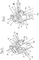
- einen Teil eines Fensters eines Kraftfahrzeugs mit einem Ausführungsbeispiel einer erfindungsgemäßen Blendenanordnung in einer perspektivischen Ansicht,
- Fig. 3
- einen Schnitt durch die Blendenanordnung gemäß
Fig. 1 , - Fig. 4
- einen Schnitt durch die Blendenanordnung gemäß
Fig. 2 und - Fig. 5
- das keilförmige Halteteil gemäß
Fig. 2 und4 in einer perspektivischen Darstellung. - Die in
Fig. 1 und3 teilweise dargestellte Fahrzeugtüre umfaßt einen Fensterrahmen 1, eine Fensterrahmen-Blende 2, eine Schachtblende 3 und ein Spiegeldreieck 4, an dem ein Rückspiegel befestigbar ist. Die Fensterscheibe 5 füllt bei geschlossenem Fenster die Fensteröffnung 6 aus. Die Fensterscheibe 5 durchdringt die Schachtblende 3. Bei geschlossenem Fenster liegt die Oberkante 7 der Fensterscheibe 5 in der Fensterrahmen-Blende 2. Die Fensterrahmen-Blende 2 folgt dem Verlauf der Oberkante 7 der Fensterscheibe 2. Wenn das Fenster geöffnet wird, wird die Fensterscheibe 5 nach unten durch die Schachtblende 3 hindurch bewegt. Die Fensterscheibe 5 ist auf diese Weise in der Türe versenkbar. - Wie aus
Fig. 3 ersichtlich ist innerhalb der Fensterrahmen-Blende 2 eine Fensterführung 8 angeordnet. Die Fensterführung 8 hat einen U-förmigen Querschnitt. Ihre Basis 9 liegt der Oberkante 7 der Fensterscheibe 5 gegenüber. Der innere Schenkel 10 der Fensterführung 8 verläuft parallel zu einem entsprechenden Abschnitt des Türblechs 11. Am Ende des inneren Schenkels 10 ist eine nach innen weisende, schräg verlaufende Dichtungsleiste 10a vorgesehen, insbesondere angeformt, die im geschlossenen Zustand des Fensters, in dem die Fensterscheibe 5 in der Fensterführung 8 liegt, wie inFig. 3 und 4 gezeigt, an der Innenseite der Fensterscheibe 5 anliegt. Der äußere Schenkel 10b der Fensterführung 8 weist ebenfalls eine nach innen gerichtete Dichtungsleiste 10c auf, die im geschlossenen Zustand des Fensters an der Außenseite der Fensterscheibe 5 anliegt. - Der äußere Schenkel 10b der Fensterführung 8 weist ferner eine Nut 12 auf, in die eine Nase 13 der Fensterrahmen-Blende 2 eingreift. Der innere Schenkel 10 der Fensterführung 8 weist eine weitere Nut 14 auf, in die das U-förmig abgebogene Ende 15 eines Schenkels der Fensterrahmen-Blende 2 eingreift. Auf diese Weise wird die Fensterführung 8 von der Fensterrahmen-Blende 2 gehalten. Die Fensterrahmen-Blende 2 ist ihrerseits an den beiden Schenkeln des Türblechs 11 befestigt. Sie ist im Querschnitt U-förmig oder L-förmig, wie in
Fig. 3 und 4 gezeigt, mit einer Verlängerung, an der eine Dichtung 2a zur Abdichtung der Fensterrahmen-Blende 2 gegenüber einem Karosserieteil oder einem Fensterrahmen vorzugsweise lösbar befestigt ist. - Wie aus
Fig. 1 ersichtlich folgt die Fensterrahmen-Blende 2 dem Verlauf der Oberkante 7 der Fensterscheibe 5. Der Abstand zwischen der Sichtfläche 16 der Fensterrahmen-Blende 2 und der Sichtfläche 17 des Fensterrahmens 1 wird mit zunehmender Annäherung an das untere Ende der Fensterrahmen-Blende 2 im Bereich des Spiegeldreiecks 4 größer. InFig. 1 ist dieser Abstand H im Endbereich der Fensterrahmen-Blende 2 im Bereich der Spiegelblende 4 eingezeichnet. In einem Abstand von der Spiegelblende 4 hat sich dieser Abstand auf das Maß h vermindert. - Um diesen Abstand zu vergleichmäßigen und auf diese Weise ein harmonischeres Design zu erreichen ist zwischen der Fensterrahmen-Blende 2 und der Fensterführung 8 gemäß
Fig. 2 ,4 und5 ein Halteteil 18 angeordnet. Das Halteteil 18 ist keilförmig. Die Stärke des Halteteils 18 nimmt in Längsrichtung durchgehend, also über die gesamte Länge des Halteteils 18 zu. Diese Stärke beträgt an dem dem Spiegeldreieck 4 abgewandten Ende des Halteteils 18 lediglich d. An dem im Bereich des Spiegeldreiecks 4 liegenden Ende beträgt die Stärke D. Der Verlauf der Stärke des Halteteils 18 ist derart gewählt, daß der Abstand h zwischen der Sichtfläche 16 der Fensterrahmen-Blende 2 und der Sichtfläche 17 des Fensterrahmens 1 über den gesamten Verlauf der Fensterrahmen-Blende 2 konstant den Wert h einnimmt, wie inFig. 2 gezeigt. - Wie insbesondere aus
Fig. 4 und5 ersichtlich weist das Halteteil 18 auf seiner der Fensterführung 8 zugewandten Seite eine Nase 19 auf, die in die Nut 12 an der Außenseite des äußeren Schenkels 10b der Fensterführung 8 eingreift. Auf seiner gegenüberliegenden, der Fensterführung 8 abgewandten und der Fensterrahmen-Blende 2 zugewandten Seite weist das Halteteil 18 eine Nut 20 auf, in die eine Nase der Fensterrahmen-Blende 2 eingreift. Die Nut 20 umfaßt einen ersten Abschnitt 21 mit einer geringeren Nuttiefe und einen zweiten Abschnitt 22 mit einer größeren Nuttiefe, die voneinander durch eine Stufe 23 getrennt sind. Die Stufe 23 kann eine weitere Haltefunktion in der Längsrichtung des Halteteils 18 übernehmen. - Die Erfindung kann bei einem versenkbaren Fenster in der Karosserie oder Türe eines Fahrzeugs oder Kraftfahrzeugs verwendet werden. Das versenkbare Fenster wird durch die Fensterführung 8 abgedichtet und geführt. Die Fensterführung 8 wird von der Fensterrahmen-Blende 2 gehalten und geführt. Um einen vom Design her gewünschten, harmonischen Verlauf zwischen der Seitenwand des Fahrzeugs bzw. dem Fensterrahmen einerseits und der Fensterrahmen-Blende andererseits zu erreichen, ist das Halteteil vorgesehen, durch das der Verlauf der Fensterrahmen-Blende geändert und an die Seitenwand des Fahrzeugs bzw. den Fensterrahmen angepaßt werden kann. Das keilförmige Halteteil 18 umfaßt eine Nase 19, um die Führungsfunktion der Fensterrahmen-Blende 2 aufrechtzuerhalten. Das Halteteil 18 ist über seine Länge keilförmig gestaltet, so daß der Verlauf der Fensterrahmen-Blende 2 harmonisch wirkt. Auf diese Weise ist es möglich, daß die Fensterrahmen-Blende 2 dem Fensterrahmen bzw. dem Seitenrahmen bzw. der Zierleiste des Seitenrahmens folgt, wie dies aus optischen Gründen erwünscht ist. Durch das Halteteil kann die Haltefunktion und Dichtungsfunktion aufrechterhalten werden. Durch die Erfindung werden dem Design neue Möglichkeiten gegeben. Die Fensterrahmen-Blende kann den Versatz zwischen der Seitenwand bzw. dem Fensterrahmen und dem versenkbaren Fenster ausgleichen.
Claims (4)
- Blendenanordnung für ein Fenster eines Fahrzeugs, insbesondere eines Kraftfahrzeugs, mit einem Fensterrahmen (1), mit einer Fensterrahmen-Blende (2), die eine Sichtfläche (16) aufweist, und mit einer Fensterführung (8), die von der Fensterrahmen-Blende (2) gehalten wird, wobei zwischen der Fensterrahmen-Blende (2) und der Fensterführung (8) ein Halteteil (18) angeordnet ist,
dadurch gekennzeichnet,
dass das Halteteil (18) über seine Länge keilförmig ist, wobei der Verlauf der Stärke des Halteteils (18) derart gewählt ist, dass der Abstand (h) zwischen der Sichtfläche (16) der Fensterrahmen-Blende (2) und der Sichtfläche (17) des Fensterrahmens (1) oder einer Sichtfläche der angrenzenden Türe oder einer Sichtfläche der angrenzenden Karosserie über den gesamten Verlauf der Fensterrahmen-Blende (2) einen konstanten Wert (h) einnimmt. - Blendenanordnung nach Anspruch 1, dadurch gekennzeichnet, dass das Halteteil (18) eine Nase (19) aufweist.
- Blendenanordnung nach einem der vorhergehenden Ansprüche, dadurch gekennzeichnet, daß das Halteteil (18) eine Nut (20) aufweist.
- Fahrzeug, insbesondere Kraftfahrzeug, gekennzeichnet durch eine oder mehrere Blendenanordnungen nach einem oder mehreren der Ansprüche 1 bis 3.
Applications Claiming Priority (1)
| Application Number | Priority Date | Filing Date | Title |
|---|---|---|---|
| DE102009018830A DE102009018830A1 (de) | 2009-04-24 | 2009-04-24 | Blendenanordnung für ein Fenster eines Kraftfahrzeugs |
Publications (3)
| Publication Number | Publication Date |
|---|---|
| EP2243650A2 EP2243650A2 (de) | 2010-10-27 |
| EP2243650A3 EP2243650A3 (de) | 2012-06-27 |
| EP2243650B1 true EP2243650B1 (de) | 2016-07-20 |
Family
ID=42352282
Family Applications (1)
| Application Number | Title | Priority Date | Filing Date |
|---|---|---|---|
| EP10004222.5A Not-in-force EP2243650B1 (de) | 2009-04-24 | 2010-04-21 | Blendenanordnung für ein KFZ-Fenster |
Country Status (2)
| Country | Link |
|---|---|
| EP (1) | EP2243650B1 (de) |
| DE (1) | DE102009018830A1 (de) |
Families Citing this family (4)
| Publication number | Priority date | Publication date | Assignee | Title |
|---|---|---|---|---|
| CN103273828B (zh) * | 2013-06-18 | 2015-06-24 | 四川中邦模具有限公司 | 一种专用于汽车前风窗装饰条的骨架 |
| KR101518912B1 (ko) * | 2013-11-08 | 2015-05-11 | 현대자동차 주식회사 | 자동차의 도어 프레임 |
| DE102020116448A1 (de) | 2020-06-23 | 2021-12-23 | Bayerische Motoren Werke Aktiengesellschaft | Fensterrahmenblendenanordnung für einen Fensterrahmen eines beweglichen Fahrzeugfensters |
| DE102021129689A1 (de) | 2021-11-15 | 2023-05-17 | Cqlt Saargummi Technologies S.À.R.L. | Dichtungsanordnung für ein Kraftfahrzeug, Dichtungsprofil und Montageverfahren |
Family Cites Families (9)
| Publication number | Priority date | Publication date | Assignee | Title |
|---|---|---|---|---|
| DE2847404A1 (de) * | 1978-11-02 | 1980-05-14 | Happich Gmbh Gebr | Fenster an fahrzeugen, insbesondere seitenfenster |
| DE3312473A1 (de) * | 1983-04-07 | 1984-10-18 | Adam Opel AG, 6090 Rüsselsheim | Anordnung fuer eine in der hoehe verstellbare fensterscheibe |
| DE19727010B4 (de) * | 1997-06-25 | 2006-03-09 | Wagon Automotive Gmbh | Fensterrahmenmodul zur Herstellung von Kraftfahrzeugtüren |
| DE19922749B4 (de) | 1999-05-18 | 2004-11-11 | Bayerische Motoren Werke Ag | Dichtung für eine Fensterscheibe |
| DE10134465C1 (de) | 2001-07-16 | 2002-12-05 | Metzeler Automotive Profile | Dichtung, insbesondere zum Abdichten einer in einer Kraftfahrzeugtür verschiebbar angeordneten Fensterscheibe |
| DE10335942A1 (de) * | 2003-08-04 | 2005-03-10 | Volkswagen Ag | Türdichtungsanordnung |
| DE102004063509A1 (de) * | 2004-12-27 | 2006-07-06 | Brose Fahrzeugteile Gmbh & Co. Kommanditgesellschaft, Coburg | Fensterbaugruppe für ein Kraftfahrzeug |
| DE102005042123A1 (de) * | 2005-09-06 | 2007-03-08 | Bayerische Motoren Werke Ag | Tür für ein Kraftfahrzeug |
| DE102006053094A1 (de) * | 2006-11-10 | 2008-05-15 | Metzeler Automotive Profile Systems Gmbh | Dichtung und Dichtungsanordnung zum Abdichten von Fensterscheiben eines Kraftfahrzeugs |
-
2009
- 2009-04-24 DE DE102009018830A patent/DE102009018830A1/de not_active Ceased
-
2010
- 2010-04-21 EP EP10004222.5A patent/EP2243650B1/de not_active Not-in-force
Also Published As
| Publication number | Publication date |
|---|---|
| DE102009018830A1 (de) | 2010-11-11 |
| EP2243650A2 (de) | 2010-10-27 |
| EP2243650A3 (de) | 2012-06-27 |
Similar Documents
| Publication | Publication Date | Title |
|---|---|---|
| EP2352658B1 (de) | Scheibenfassung | |
| DE202007003837U1 (de) | Dichtungsprofil und dieses einbeziehende Dichtungsanordnung | |
| DE102014010420B4 (de) | Fahrzeugdach mit einem Dachmodul | |
| DE102019213427A1 (de) | Fensterführung für eine Fensterscheibe eines Kraftfahrzeugs | |
| EP2243650B1 (de) | Blendenanordnung für ein KFZ-Fenster | |
| DE3210468A1 (de) | Tuer- und fensterrahmen | |
| DE10122637B4 (de) | Dichtungsanordnung für eine Kraftfahrzeugtüre und/oder ein Kraftfahrzeugfenster | |
| DE102019208772B4 (de) | Befestigungsanordnung für eine Fensterschachtleiste | |
| EP1087092B1 (de) | Profilelement | |
| EP3168085A1 (de) | Überbrückungsbauteil und bordkantenzierleiste sowie system hieraus | |
| EP2784262B1 (de) | Schrank mit Rollo | |
| WO2021069463A1 (de) | Verschlussanordnung sowie schrank- oder kastenmöbel | |
| DE68903575T2 (de) | Sonnendach fuer ein fahrzeug. | |
| DE19744907B4 (de) | Verfahren zum Herstellen von Führungsschienen für einen verschiebbaren Dachteil und ein Sonnenschutzrollo für ein Fahrzeugdach | |
| DE102010044596A1 (de) | Rollladenpanzer | |
| DE202004016232U1 (de) | Profilelement | |
| DE102019208927B4 (de) | Flexibles Andruckelement | |
| LU101158B1 (de) | Verbindungselement mit zwei unabhängigen Haltevorrichtungen | |
| DE20218156U1 (de) | Fensterschacht-Abdeckvorrichtung | |
| DE20118295U1 (de) | Schiebefenster | |
| DE102005029301B3 (de) | Heckscheibe in einem hinteren Dachabschnitt eines öffnungsfähigen Fahrzeugdaches | |
| DE10205960B4 (de) | Deckel für eine Dachöffnung eines Kraftwagens | |
| EP1944452A2 (de) | Sektionaltor mit Schlupftür im Torblatt | |
| DE1888081U (de) | Abdichtungsprofil, insbesondere zur Abdichtung von beweglichen Teilen bei Kraftfahrzeugen | |
| DE29511692U1 (de) | Vorrichtung zum Begrenzen der Öffnungsbewegung, Verhindern des Zuschlagens und/oder Feststellen des Flügels eines Fensters oder einer Tür in wenigstens einer Offenstellung |
Legal Events
| Date | Code | Title | Description |
|---|---|---|---|
| PUAI | Public reference made under article 153(3) epc to a published international application that has entered the european phase |
Free format text: ORIGINAL CODE: 0009012 |
|
| AK | Designated contracting states |
Kind code of ref document: A2 Designated state(s): AT BE BG CH CY CZ DE DK EE ES FI FR GB GR HR HU IE IS IT LI LT LU LV MC MK MT NL NO PL PT RO SE SI SK SM TR |
|
| AX | Request for extension of the european patent |
Extension state: AL BA ME RS |
|
| PUAL | Search report despatched |
Free format text: ORIGINAL CODE: 0009013 |
|
| AK | Designated contracting states |
Kind code of ref document: A3 Designated state(s): AT BE BG CH CY CZ DE DK EE ES FI FR GB GR HR HU IE IS IT LI LT LU LV MC MK MT NL NO PL PT RO SE SI SK SM TR |
|
| AX | Request for extension of the european patent |
Extension state: AL BA ME RS |
|
| RIC1 | Information provided on ipc code assigned before grant |
Ipc: B60J 10/04 20060101ALI20120522BHEP Ipc: B60J 10/00 20060101AFI20120522BHEP |
|
| 17P | Request for examination filed |
Effective date: 20121212 |
|
| 17Q | First examination report despatched |
Effective date: 20140218 |
|
| GRAP | Despatch of communication of intention to grant a patent |
Free format text: ORIGINAL CODE: EPIDOSNIGR1 |
|
| RIC1 | Information provided on ipc code assigned before grant |
Ipc: B60J 10/00 20160101AFI20160215BHEP |
|
| INTG | Intention to grant announced |
Effective date: 20160317 |
|
| GRAS | Grant fee paid |
Free format text: ORIGINAL CODE: EPIDOSNIGR3 |
|
| GRAA | (expected) grant |
Free format text: ORIGINAL CODE: 0009210 |
|
| RAP1 | Party data changed (applicant data changed or rights of an application transferred) |
Owner name: DURA AUTOMOTIVE BODY AND GLASS SYSTEMS GMBH |
|
| AK | Designated contracting states |
Kind code of ref document: B1 Designated state(s): AT BE BG CH CY CZ DE DK EE ES FI FR GB GR HR HU IE IS IT LI LT LU LV MC MK MT NL NO PL PT RO SE SI SK SM TR |
|
| REG | Reference to a national code |
Ref country code: GB Ref legal event code: FG4D Free format text: NOT ENGLISH |
|
| REG | Reference to a national code |
Ref country code: CH Ref legal event code: EP |
|
| REG | Reference to a national code |
Ref country code: IE Ref legal event code: FG4D Free format text: LANGUAGE OF EP DOCUMENT: GERMAN |
|
| REG | Reference to a national code |
Ref country code: AT Ref legal event code: REF Ref document number: 813762 Country of ref document: AT Kind code of ref document: T Effective date: 20160815 |
|
| REG | Reference to a national code |
Ref country code: DE Ref legal event code: R096 Ref document number: 502010012033 Country of ref document: DE |
|
| REG | Reference to a national code |
Ref country code: LT Ref legal event code: MG4D |
|
| REG | Reference to a national code |
Ref country code: NL Ref legal event code: MP Effective date: 20160720 |
|
| REG | Reference to a national code |
Ref country code: DE Ref legal event code: R081 Ref document number: 502010012033 Country of ref document: DE Owner name: PLASMAN EUROPE AB, SE Free format text: FORMER OWNER: DURA AUTOMOTIVE BODY AND GLASS SYSTEMS GMBH, 58840 PLETTENBERG, DE Ref country code: DE Ref legal event code: R082 Ref document number: 502010012033 Country of ref document: DE Representative=s name: LORENZ SEIDLER GOSSEL RECHTSANWAELTE PATENTANW, DE Ref country code: DE Ref legal event code: R081 Ref document number: 502010012033 Country of ref document: DE Owner name: DURA AUTOMOTIVE HOLDINGS U.K., LTD., CASTLE VA, GB Free format text: FORMER OWNER: DURA AUTOMOTIVE BODY AND GLASS SYSTEMS GMBH, 58840 PLETTENBERG, DE |
|
| PG25 | Lapsed in a contracting state [announced via postgrant information from national office to epo] |
Ref country code: FI Free format text: LAPSE BECAUSE OF FAILURE TO SUBMIT A TRANSLATION OF THE DESCRIPTION OR TO PAY THE FEE WITHIN THE PRESCRIBED TIME-LIMIT Effective date: 20160720 Ref country code: NL Free format text: LAPSE BECAUSE OF FAILURE TO SUBMIT A TRANSLATION OF THE DESCRIPTION OR TO PAY THE FEE WITHIN THE PRESCRIBED TIME-LIMIT Effective date: 20160720 Ref country code: IS Free format text: LAPSE BECAUSE OF FAILURE TO SUBMIT A TRANSLATION OF THE DESCRIPTION OR TO PAY THE FEE WITHIN THE PRESCRIBED TIME-LIMIT Effective date: 20161120 Ref country code: NO Free format text: LAPSE BECAUSE OF FAILURE TO SUBMIT A TRANSLATION OF THE DESCRIPTION OR TO PAY THE FEE WITHIN THE PRESCRIBED TIME-LIMIT Effective date: 20161020 Ref country code: LT Free format text: LAPSE BECAUSE OF FAILURE TO SUBMIT A TRANSLATION OF THE DESCRIPTION OR TO PAY THE FEE WITHIN THE PRESCRIBED TIME-LIMIT Effective date: 20160720 Ref country code: HR Free format text: LAPSE BECAUSE OF FAILURE TO SUBMIT A TRANSLATION OF THE DESCRIPTION OR TO PAY THE FEE WITHIN THE PRESCRIBED TIME-LIMIT Effective date: 20160720 Ref country code: IT Free format text: LAPSE BECAUSE OF FAILURE TO SUBMIT A TRANSLATION OF THE DESCRIPTION OR TO PAY THE FEE WITHIN THE PRESCRIBED TIME-LIMIT Effective date: 20160720 |
|
| PG25 | Lapsed in a contracting state [announced via postgrant information from national office to epo] |
Ref country code: LV Free format text: LAPSE BECAUSE OF FAILURE TO SUBMIT A TRANSLATION OF THE DESCRIPTION OR TO PAY THE FEE WITHIN THE PRESCRIBED TIME-LIMIT Effective date: 20160720 Ref country code: ES Free format text: LAPSE BECAUSE OF FAILURE TO SUBMIT A TRANSLATION OF THE DESCRIPTION OR TO PAY THE FEE WITHIN THE PRESCRIBED TIME-LIMIT Effective date: 20160720 Ref country code: SE Free format text: LAPSE BECAUSE OF FAILURE TO SUBMIT A TRANSLATION OF THE DESCRIPTION OR TO PAY THE FEE WITHIN THE PRESCRIBED TIME-LIMIT Effective date: 20160720 Ref country code: PL Free format text: LAPSE BECAUSE OF FAILURE TO SUBMIT A TRANSLATION OF THE DESCRIPTION OR TO PAY THE FEE WITHIN THE PRESCRIBED TIME-LIMIT Effective date: 20160720 Ref country code: GR Free format text: LAPSE BECAUSE OF FAILURE TO SUBMIT A TRANSLATION OF THE DESCRIPTION OR TO PAY THE FEE WITHIN THE PRESCRIBED TIME-LIMIT Effective date: 20161021 Ref country code: PT Free format text: LAPSE BECAUSE OF FAILURE TO SUBMIT A TRANSLATION OF THE DESCRIPTION OR TO PAY THE FEE WITHIN THE PRESCRIBED TIME-LIMIT Effective date: 20161121 |
|
| REG | Reference to a national code |
Ref country code: DE Ref legal event code: R097 Ref document number: 502010012033 Country of ref document: DE |
|
| PG25 | Lapsed in a contracting state [announced via postgrant information from national office to epo] |
Ref country code: RO Free format text: LAPSE BECAUSE OF FAILURE TO SUBMIT A TRANSLATION OF THE DESCRIPTION OR TO PAY THE FEE WITHIN THE PRESCRIBED TIME-LIMIT Effective date: 20160720 Ref country code: EE Free format text: LAPSE BECAUSE OF FAILURE TO SUBMIT A TRANSLATION OF THE DESCRIPTION OR TO PAY THE FEE WITHIN THE PRESCRIBED TIME-LIMIT Effective date: 20160720 |
|
| REG | Reference to a national code |
Ref country code: FR Ref legal event code: PLFP Year of fee payment: 8 |
|
| PLBE | No opposition filed within time limit |
Free format text: ORIGINAL CODE: 0009261 |
|
| STAA | Information on the status of an ep patent application or granted ep patent |
Free format text: STATUS: NO OPPOSITION FILED WITHIN TIME LIMIT |
|
| PG25 | Lapsed in a contracting state [announced via postgrant information from national office to epo] |
Ref country code: CZ Free format text: LAPSE BECAUSE OF FAILURE TO SUBMIT A TRANSLATION OF THE DESCRIPTION OR TO PAY THE FEE WITHIN THE PRESCRIBED TIME-LIMIT Effective date: 20160720 Ref country code: SK Free format text: LAPSE BECAUSE OF FAILURE TO SUBMIT A TRANSLATION OF THE DESCRIPTION OR TO PAY THE FEE WITHIN THE PRESCRIBED TIME-LIMIT Effective date: 20160720 Ref country code: SM Free format text: LAPSE BECAUSE OF FAILURE TO SUBMIT A TRANSLATION OF THE DESCRIPTION OR TO PAY THE FEE WITHIN THE PRESCRIBED TIME-LIMIT Effective date: 20160720 Ref country code: BG Free format text: LAPSE BECAUSE OF FAILURE TO SUBMIT A TRANSLATION OF THE DESCRIPTION OR TO PAY THE FEE WITHIN THE PRESCRIBED TIME-LIMIT Effective date: 20161020 Ref country code: DK Free format text: LAPSE BECAUSE OF FAILURE TO SUBMIT A TRANSLATION OF THE DESCRIPTION OR TO PAY THE FEE WITHIN THE PRESCRIBED TIME-LIMIT Effective date: 20160720 |
|
| 26N | No opposition filed |
Effective date: 20170421 |
|
| REG | Reference to a national code |
Ref country code: FR Ref legal event code: TP Owner name: DURA AUTOMOTIVE BODY AND GLASS SYSTEMS GMBH, DE Effective date: 20170629 |
|
| REG | Reference to a national code |
Ref country code: GB Ref legal event code: 732E Free format text: REGISTERED BETWEEN 20170727 AND 20170802 |
|
| PG25 | Lapsed in a contracting state [announced via postgrant information from national office to epo] |
Ref country code: SI Free format text: LAPSE BECAUSE OF FAILURE TO SUBMIT A TRANSLATION OF THE DESCRIPTION OR TO PAY THE FEE WITHIN THE PRESCRIBED TIME-LIMIT Effective date: 20160720 |
|
| REG | Reference to a national code |
Ref country code: CH Ref legal event code: PL |
|
| REG | Reference to a national code |
Ref country code: IE Ref legal event code: MM4A |
|
| PG25 | Lapsed in a contracting state [announced via postgrant information from national office to epo] |
Ref country code: MC Free format text: LAPSE BECAUSE OF FAILURE TO SUBMIT A TRANSLATION OF THE DESCRIPTION OR TO PAY THE FEE WITHIN THE PRESCRIBED TIME-LIMIT Effective date: 20160720 |
|
| PG25 | Lapsed in a contracting state [announced via postgrant information from national office to epo] |
Ref country code: LU Free format text: LAPSE BECAUSE OF NON-PAYMENT OF DUE FEES Effective date: 20170421 Ref country code: LI Free format text: LAPSE BECAUSE OF NON-PAYMENT OF DUE FEES Effective date: 20170430 Ref country code: CH Free format text: LAPSE BECAUSE OF NON-PAYMENT OF DUE FEES Effective date: 20170430 |
|
| REG | Reference to a national code |
Ref country code: BE Ref legal event code: MM Effective date: 20170430 |
|
| REG | Reference to a national code |
Ref country code: FR Ref legal event code: PLFP Year of fee payment: 9 |
|
| PG25 | Lapsed in a contracting state [announced via postgrant information from national office to epo] |
Ref country code: IE Free format text: LAPSE BECAUSE OF NON-PAYMENT OF DUE FEES Effective date: 20170421 |
|
| PG25 | Lapsed in a contracting state [announced via postgrant information from national office to epo] |
Ref country code: BE Free format text: LAPSE BECAUSE OF NON-PAYMENT OF DUE FEES Effective date: 20170430 |
|
| REG | Reference to a national code |
Ref country code: AT Ref legal event code: MM01 Ref document number: 813762 Country of ref document: AT Kind code of ref document: T Effective date: 20170421 |
|
| PG25 | Lapsed in a contracting state [announced via postgrant information from national office to epo] |
Ref country code: AT Free format text: LAPSE BECAUSE OF NON-PAYMENT OF DUE FEES Effective date: 20170421 |
|
| PG25 | Lapsed in a contracting state [announced via postgrant information from national office to epo] |
Ref country code: MT Free format text: LAPSE BECAUSE OF FAILURE TO SUBMIT A TRANSLATION OF THE DESCRIPTION OR TO PAY THE FEE WITHIN THE PRESCRIBED TIME-LIMIT Effective date: 20160720 |
|
| PG25 | Lapsed in a contracting state [announced via postgrant information from national office to epo] |
Ref country code: HU Free format text: LAPSE BECAUSE OF FAILURE TO SUBMIT A TRANSLATION OF THE DESCRIPTION OR TO PAY THE FEE WITHIN THE PRESCRIBED TIME-LIMIT; INVALID AB INITIO Effective date: 20100421 |
|
| PG25 | Lapsed in a contracting state [announced via postgrant information from national office to epo] |
Ref country code: CY Free format text: LAPSE BECAUSE OF NON-PAYMENT OF DUE FEES Effective date: 20160720 |
|
| PG25 | Lapsed in a contracting state [announced via postgrant information from national office to epo] |
Ref country code: MK Free format text: LAPSE BECAUSE OF FAILURE TO SUBMIT A TRANSLATION OF THE DESCRIPTION OR TO PAY THE FEE WITHIN THE PRESCRIBED TIME-LIMIT Effective date: 20160720 |
|
| PG25 | Lapsed in a contracting state [announced via postgrant information from national office to epo] |
Ref country code: TR Free format text: LAPSE BECAUSE OF FAILURE TO SUBMIT A TRANSLATION OF THE DESCRIPTION OR TO PAY THE FEE WITHIN THE PRESCRIBED TIME-LIMIT Effective date: 20160720 |
|
| REG | Reference to a national code |
Ref country code: DE Ref legal event code: R081 Ref document number: 502010012033 Country of ref document: DE Owner name: PLASMAN EUROPE AB, SE Free format text: FORMER OWNER: DURA AUTOMOTIVE HOLDINGS U.K., LTD., CASTLE VALE, BIRMINGHAM, GB Ref country code: DE Ref legal event code: R082 Ref document number: 502010012033 Country of ref document: DE Representative=s name: BTB IP BUNGARTZ BALTZER PARTNERSCHAFT MBB PATE, DE |
|
| REG | Reference to a national code |
Ref country code: GB Ref legal event code: 732E Free format text: REGISTERED BETWEEN 20220623 AND 20220629 |
|
| PGFP | Annual fee paid to national office [announced via postgrant information from national office to epo] |
Ref country code: GB Payment date: 20220427 Year of fee payment: 13 Ref country code: FR Payment date: 20220425 Year of fee payment: 13 Ref country code: DE Payment date: 20220427 Year of fee payment: 13 |
|
| REG | Reference to a national code |
Ref country code: DE Ref legal event code: R119 Ref document number: 502010012033 Country of ref document: DE |
|
| GBPC | Gb: european patent ceased through non-payment of renewal fee |
Effective date: 20230421 |
|
| PG25 | Lapsed in a contracting state [announced via postgrant information from national office to epo] |
Ref country code: GB Free format text: LAPSE BECAUSE OF NON-PAYMENT OF DUE FEES Effective date: 20230421 |
|
| PG25 | Lapsed in a contracting state [announced via postgrant information from national office to epo] |
Ref country code: GB Free format text: LAPSE BECAUSE OF NON-PAYMENT OF DUE FEES Effective date: 20230421 Ref country code: FR Free format text: LAPSE BECAUSE OF NON-PAYMENT OF DUE FEES Effective date: 20230430 Ref country code: DE Free format text: LAPSE BECAUSE OF NON-PAYMENT OF DUE FEES Effective date: 20231103 |