EP1583226A2 - Funk-Kommunikationsgerät - Google Patents
Funk-Kommunikationsgerät Download PDFInfo
- Publication number
- EP1583226A2 EP1583226A2 EP05252039A EP05252039A EP1583226A2 EP 1583226 A2 EP1583226 A2 EP 1583226A2 EP 05252039 A EP05252039 A EP 05252039A EP 05252039 A EP05252039 A EP 05252039A EP 1583226 A2 EP1583226 A2 EP 1583226A2
- Authority
- EP
- European Patent Office
- Prior art keywords
- signal
- output
- harmonic
- amplifier
- communication device
- Prior art date
- Legal status (The legal status is an assumption and is not a legal conclusion. Google has not performed a legal analysis and makes no representation as to the accuracy of the status listed.)
- Granted
Links
- 238000004891 communication Methods 0.000 title claims abstract description 41
- 230000010355 oscillation Effects 0.000 claims abstract description 37
- 229920006395 saturated elastomer Polymers 0.000 claims description 4
- 238000010586 diagram Methods 0.000 description 13
- 238000005516 engineering process Methods 0.000 description 4
- 230000005540 biological transmission Effects 0.000 description 3
- 238000001228 spectrum Methods 0.000 description 3
- 239000003990 capacitor Substances 0.000 description 2
- 230000000694 effects Effects 0.000 description 2
- 230000007613 environmental effect Effects 0.000 description 2
- 238000000034 method Methods 0.000 description 2
- 238000012986 modification Methods 0.000 description 1
- 230000004048 modification Effects 0.000 description 1
- 238000012827 research and development Methods 0.000 description 1
Images


Classifications
-
- H—ELECTRICITY
- H03—ELECTRONIC CIRCUITRY
- H03D—DEMODULATION OR TRANSFERENCE OF MODULATION FROM ONE CARRIER TO ANOTHER
- H03D9/00—Demodulation or transference of modulation of modulated electromagnetic waves
- H03D9/06—Transference of modulation using distributed inductance and capacitance
- H03D9/0608—Transference of modulation using distributed inductance and capacitance by means of diodes
- H03D9/0633—Transference of modulation using distributed inductance and capacitance by means of diodes mounted on a stripline circuit
-
- H—ELECTRICITY
- H04—ELECTRIC COMMUNICATION TECHNIQUE
- H04B—TRANSMISSION
- H04B1/00—Details of transmission systems, not covered by a single one of groups H04B3/00 - H04B13/00; Details of transmission systems not characterised by the medium used for transmission
- H04B1/02—Transmitters
- H04B1/04—Circuits
Definitions
- This invention generally relates to radio communication devices, and more particularly, to a transmission technology suitable for a high frequency range as high as at least 30 GHz.
- Japanese Patent Application Publication No. 2001-53640 (hereinafter referred to as Document 1) describes a technique for transmitting an unmodulated carrier having a local oscillation frequency together with a modulated radio signal.
- the received unmodulated carrier is used as the local oscillation frequency to demodulate the modulated radio signal. It is not necessary to provide a high-accuracy local oscillator on the receiver. It is thus possible to simplify the structure of the receiver.
- the unmodulated carrier and the modulated radio carrier are affected by the same environmental factor such as temperature change, the affect of the environmental factor (fluctuations due to the temperature change) can be cancelled by demodulating with the received unmodulated carrier, and an excellent communication quality can be thus provided.
- the invention disclosed in Document 1 employs a local oscillator that generates the oscillation frequency identical to that of the unmodulated carrier to be output from an antenna.
- the stable modulated radio carrier cannot be generated.
- the local oscillator capable of stably generating the oscillation frequency of at least 30 GHz there are still drawbacks to be solved even with the use of current technology.
- an extremely advanced technology and a considerable cost are required for producing the local oscillator having a frequency range as high as 60 GHz in order to realize the millimeter-wave radio communication with a frequency range of 60 GHz, which is considered attractive these days.
- a radio communication device comprising: a local oscillator; an amplifier amplifying an output signal of the local oscillator and outputting a local oscillation frequency and a harmonic wave component thereof; and a harmonic mixer receiving an output signal of the amplifier and an information signal, and generating an up-converted signal of the information signal with the harmonic wave component based on the local oscillation frequency, while allowing the harmonic wave component to pass through.
- the harmonic wave component is generated by the amplifier and is caused to pass through the harmonic mixer. It is thus possible to transmit the harmonic wave component of the oscillation signal of the local oscillator together with the up-converted signal.
- the local oscillator may be enough to oscillate a comparatively low frequency, so that the radio communications using the frequency range as high as 30 GHz or higher can be realized by a simple structure at a low cost.
- a radio communication device comprising: a local oscillator; an amplifier amplifying an output signal of the local oscillator and outputting an amplified signal including a harmonic wave component of the output signal of the local oscillator; and a harmonic mixer mixing the output signal of the local oscillator with an information signal to output an up-converted signal of the information signal.
- Fig. 1 is a block diagram of a ratio communication device 100 in accordance with a first embodiment of the present invention.
- the radio communication device 100 includes a harmonic mixer 20, a local oscillator 22, an amplifier 24, a power amplifier 26, and an external connection terminal 29.
- the local oscillator 22 generates a local oscillation signal of a frequency f LO .
- the amplifier 24 is configured so as to have a linear gain region and a saturated gain region over which region the frequency range of the oscillation output signal of the local oscillator 22 is located.
- Fig. 2 is a graph showing input-output characteristics of the amplifier 24.
- the amplifier 24 amplifies the oscillation output signal generated by the local oscillator 22 with the use of both the linear region and the saturated gain region shown in Fig. 2. As shown in Fig.
- the amplified oscillation output signal is not a linearly amplified signal S1 but a distorted signal S2 .
- the distorted signal S2 includes harmonic wave components such as a second harmonic wave and a third harmonic wave, in addition to a fundamental harmonic wave of a frequency f LO .
- n•f LO denotes the frequency components of the output signal of the amplifier 24 where n is a positive integer.
- the output signal of the amplifier 24 is applied to a first terminal of the harmonic mixer 20.
- An information signal IF of a frequency f IF is applied to a second terminal of the harmonic mixer 20.
- the harmonic mixer 20 generates n-time waves n•f LO of the frequency component f LO included in the output signal of the amplifier 24, mixes the harmonic wave components with the information signal IF, and makes the harmonic wave components n•f LO pass through, the harmonic wave components being included in the output signal of the amplifier 24.
- a description will be directed to only the fundamental harmonic wave of the frequency f LO (the local oscillation signal) and the second harmonic wave (the frequency 2f LO ) among the output waves of the amplifier 24, and will be given of a case where the harmonic mixer 20 generates only the second harmonic of the frequency 2f LO of the fundamental harmonic wave f LO .
- the harmonic mixer 20 generates the double wave 2f LO of the fundamental harmonic wave f LO output from the amplifier 24, and mixes the double wave 2f LO with the information signal IF to output up-converted frequencies 2f LO ⁇ f IF , while allowing the second harmonic wave 2f LO from the amplifier 24 to pass through without change.
- the harmonic mixer 20 results in combined signals of the frequency 2f LO and the frequencies 2f LO ⁇ f IF .
- the output from the harmonic mixer 20 includes the signal component of the frequency 2f LO and the signal components of the frequencies 2f LO ⁇ f IF .
- the output of the harmonic mixer 20 includes the frequency component of n•f LO and the frequency components of n ⁇ f LO ⁇ f IF .
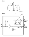
- Fig. 4 shows a frequency spectrum of the output signal of the harmonic mixer 20.
- the signal in the center of Fig. 4 has the frequency n•f LO , which has passed through the harmonic mixer 20 from the amplifier 24.
- the side band on the right has the center frequency n•f LO + f IF
- the side band on the left has the center frequency n•f LO - f IF .
- f LO is 30 GHz
- f IF is 5 GHz
- n is 2
- the harmonic mixer 20 has the signal of 60 GHz and modulated radio signals of 65 GHz and 55 GHz.
- the signal of 60 GHz is the local oscillation signal for antenna transmission, and is transmitted into the air together with the two modulated signals through the amplifier 26, the external connection terminal 29, and the antenna 40.
- the harmonic wave components generated on the amplifier 24 are applied to the harmonic mixer 20.
- the harmonic wave components generate higher frequencies due to the function of the harmonic mixer 20, and then the higher frequencies are mixed with the information signal IF.
- the intensity or power of the harmonic wave components applied to the harmonic mixer 20 is weakened, as the harmonic wave components have higher orders. These harmonic wave components cannot drive the harmonic mixer 20 sufficiently. Therefore, the harmonic wave components of high orders do not substantially affect the harmonic mixer 20.
- the harmonic wave component of interest generated on the amplifier 24 passes through the harmonic mixer 20.
- the frequency of the double wave is close to the mixing frequency (target frequency) output from the harmonic mixer 20. Therefore, the frequency of the double wave is finally output to the outside.
- the triple wave and higher-order waves have originally weak intensities, and are located outside of the allowable frequency range of a circuit arranged at a rear stage. Therefore, these waves do not substantially affect the operation of the harmonic mixer 20.
- the radio communication device 100 employs the single local oscillator 22 is included, nevertheless the device 100 is capable of generating and outputting the local oscillation signal transmitted through the antenna having the frequency of n•f LO equal to n times the local oscillation frequency f LO .
- the local oscillator 22 may have the oscillation frequency of 1/n of a desired local oscillation signal transmitted through the antenna.
- the local oscillator 22 of 30 GHz may be prepared. It is thus possible to realize the simple, less-expensive radio communication device 100 suitable for a high frequency range of 30 GHz or higher.
- both the local oscillation signal transmitted through the antenna and the modulated radio signals pass through the harmonic mixer 20, and are affected by fluctuations of the harmonic mixer 20 in the same manner.
- the fluctuations on the harmonic mixer 20 can be cancelled by a demodulation process on the receiver with the use of the local oscillation signal transmitted through the antenna.
- the power amplifier 26 is not involved in the operation of generating the frequency n•f LO equal to n times of the oscillation frequency f LO . and may be omitted as necessary.
- Fig. 5 is a circuit diagram of the harmonic mixer 20 in which circuit components are connected by ideal lines for the sake of simplicity.
- the harmonic mixer 20 includes an anti-parallel diode (hereinafter, referred to as APDP) 202.
- the APDP 202 includes two diodes D1 and D2 connected in parallel in the reverse directions between two ends.
- Fig. 6 is a graph showing a current-voltage characteristic of the APDP 202.
- An input signal is fed to one end of the APDP 202, which generates the harmonic waves of the input signal by utilizing the nonlinear regions in the current-voltage characteristic.
- the output signal of the amplifier 24 is fed to one end of the APDP 202 through the external connection terminal 214.
- the information signal IF is applied to the other end of the APDP 202 through an external connection terminal 210, a decoupling capacitor C3, and a lowpass filter 208.
- the information signal IF has a frequencies of ⁇ 5 GHz.
- the lowpass filter 208 includes two capacitors C1 and C2 and an inductor L1 An open stub 204 and a short stub 206 are provided, as necessary, for suppressing the signal loss and improving the efficiency.
- the APDP 202 utilizes the nonlinear regions of the input-output characteristics shown in Fig. 6, and generates the second harmonic wave of 60 GHz of the local oscillation frequency of 30 GHz, which is applied to one end of the APDP 202.
- the second harmonic wave of 60 GHz is mixed with the information signal IF of ⁇ 5 GHz at the other end of the APDP 202.
- the modulated radio signals of 55 GHz and 65 GHz are output to the outside through the external connection terminal 29.
- the signal of 60 GHz and the signals of 65 GHz and 55 GHz are available at the external connection terminal 29.
- the signal of 60 GHz is transmitted into the air as the local oscillation signal transmitted, together with the modulated radio signals of 55 GHz and 65 GHz via the antenna 40 shown in Fig. 1.
- the open stub 204 and the short stub 206 are provided for suppressing the signal loss and improving the efficiency.
- the open stub 204 is connected to the output side of the APDP 202, and has a length equal to 1/4 of the wavelength corresponding to the local oscillation frequency f LO generated by the local oscillator 22.
- the open end of the open stub 204 serves as ground, with respect to the signal of the local oscillation frequency f LO (30 GHz in the above-mentioned example). It is thus possible to apply the signal of 30 GHz effectively across the APDP 202.
- the open stub 204 does not function with respect to the signal of 60 GHz at all.
- the short stub 206 is connected to the input side of the APDP 202, and has a length equal to 1/4 of the wavelength corresponding to either one of the modulated radio signals 2•f LO ⁇ f IF (one of 55 GHz and 65 GHz in the above-mentioned example).
- the modulated radio signal of 65 GHz is effectively applied between the input side of the APDP 202 and the ground.
- the modulated radio signal of 65 GHz can be returned to the APDP 202.
- the short stub 206 may have a length equal to 1/4 of the wavelength corresponding to the modulated radio signal of 55 GHz.
- the modulated radio signal may transmit both sidebands or either sideband. In the case where only one of the sidebands is transmitted, one short stub 206 may be provided. In the case where both sidebands are transmitted, preferably, another short stub 208 is provided as shown in Fig. 7, so that the two short stubs 206 and 208 are respectively provided to the modulated radio signals of 55 GHz and 65 GHz.
- the harmonic mixer 20 is capable of allowing the local oscillation frequency transmitted through the antenna to pass through and generating the modulated radio signal effectively.
- the harmonic mixer 20 may be followed by a bandpass filter 28, which can eliminate unnecessary frequency components.
- a bandpass filter 28 which can eliminate unnecessary frequency components.
- an amplifier 24A may follow the amplifier 24.
- the amplifier 24A linearly amplifies the second harmonic wave.
- the gain of the amplifier 24A may be changeable.
- a bandpass filter may follow the amplifier 24 to supply the harmonic mixer 20 with only the local oscillation frequency f LO and the second harmonic wave 2•f LO .
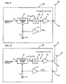
- Fig. 9 is a block diagram of a radio communication device 200 according to a second embodiment of the present invention.
- the radio communication device 200 includes the harmonic mixer 20, the local oscillator 22, the amplifier 24, the bandpass filter 28, the power amplifier 26, and the external connection terminal 29.
- the output signal of the local oscillator 22 is applied to the harmonic mixer 20 and the amplifier 24.
- the harmonic mixer 20 generates n-time waves equal to n times of the frequency component n•f LO included in the output signal of the amplifier 24, and combines the n-time waves with the information signal IF.
- n•f LO ⁇ f IF are different from those of the harmonic mixer 20 in Fig. 1.
- the output signal of the harmonic mixer 20 passes through the bandpass filter 28, and is fed to the power amplifier 26.
- the amplifier 24 has a configuration in which the frequency range of the oscillation output signal of the local oscillator 22 are located in both the linear gain region and the saturated gain region.
- the output signal of the amplifier 24 is combined with the output signal of the harmonic mixer 20 that passes through the bandpass filter 28. Therefore, the power amplifier 26 electrically amplifies the signals of the local oscillation frequency n•f LO and the frequencies f LO ⁇ f IF , and transmits the output signals through the antenna 40, which is connected to the external connection terminal 29.
- the radio communication device 200 includes the local oscillator 22, the amplifier 24, and the harmonic mixer 20, and brings about the same effect as that of the first embodiment of the present invention.
- the amplifier 24 amplifies the output signal of the local oscillator 22 and outputs the signal having the harmonic wave components.
- the harmonic mixer 20 combines the output signal of the local oscillator 24 with the information signal IF to output the up-converted signals of the information signal.
- the output signal of the amplifier 24 may be transmitted from another antenna 50 rather than the antenna 40.
- This configuration is different from that in Fig. 9.
- the oscillation signal for antenna transmission may be transmitted from another antenna, which is different from the antenna for the modulated radio signal(s).
- the antenna 50 is connected to the external connection terminal 39.
- an amplifier 24B is included for linearly amplifying the output of the local oscillator 22.
- the amplifier 24B may amplify the output to a desired level and output the amplified signal to the harmonic mixer 20.
- a bandpass filter may be arranged so as to follow the amplifier 24B to apply only the local oscillation frequency f LO to the harmonic mixer 20.
- the amplifier 24 may be followed by a bandpass filter 36 to eliminate an undesired wave.
- the bandpass filter 36 lets only 2f LO pass through.
Landscapes
- Engineering & Computer Science (AREA)
- Computer Networks & Wireless Communication (AREA)
- Signal Processing (AREA)
- Physics & Mathematics (AREA)
- Electromagnetism (AREA)
- Power Engineering (AREA)
- Transmitters (AREA)
- Transceivers (AREA)
Applications Claiming Priority (2)
| Application Number | Priority Date | Filing Date | Title |
|---|---|---|---|
| JP2004105685A JP4391291B2 (ja) | 2004-03-31 | 2004-03-31 | 無線装置 |
| JP2004105685 | 2004-03-31 |
Publications (3)
| Publication Number | Publication Date |
|---|---|
| EP1583226A2 true EP1583226A2 (de) | 2005-10-05 |
| EP1583226A3 EP1583226A3 (de) | 2006-05-24 |
| EP1583226B1 EP1583226B1 (de) | 2014-02-12 |
Family
ID=34880074
Family Applications (1)
| Application Number | Title | Priority Date | Filing Date |
|---|---|---|---|
| EP05252039.2A Active EP1583226B1 (de) | 2004-03-31 | 2005-03-31 | Funk-kommunikationsgerät |
Country Status (3)
| Country | Link |
|---|---|
| US (1) | US7738844B2 (de) |
| EP (1) | EP1583226B1 (de) |
| JP (1) | JP4391291B2 (de) |
Families Citing this family (3)
| Publication number | Priority date | Publication date | Assignee | Title |
|---|---|---|---|---|
| JP4630990B2 (ja) * | 2005-12-06 | 2011-02-09 | 独立行政法人情報通信研究機構 | 双方向無線通信装置 |
| US7933576B2 (en) * | 2006-12-05 | 2011-04-26 | Electronics And Telecommunications Research Institute | Sub-harmonic mixer |
| US9331632B2 (en) * | 2012-04-18 | 2016-05-03 | Qualcomm Incorporated | Integrated circuit for mixing millimeter-wavelength signals |
Citations (2)
| Publication number | Priority date | Publication date | Assignee | Title |
|---|---|---|---|---|
| JP2001053640A (ja) | 1999-08-11 | 2001-02-23 | Communication Research Laboratory Mpt | 無線通信装置および無線通信方法 |
| JP2004105685A (ja) | 2002-09-18 | 2004-04-08 | Hideo Odagiri | 握り部ワンクッチ操作型収納式滑り止め具および杖 |
Family Cites Families (35)
| Publication number | Priority date | Publication date | Assignee | Title |
|---|---|---|---|---|
| US4083004A (en) * | 1976-06-08 | 1978-04-04 | Westinghouse Electric Corporation | Expendable repeater employing harmonic mixing |
| US4206421A (en) * | 1976-09-17 | 1980-06-03 | Siemens Aktiengesellschaft | Arrangement for synchronizing a free-swinging oscillator |
| US6677882B1 (en) * | 1977-02-24 | 2004-01-13 | The United States Of America As Represented By The Secretary Of The Navy | Multi-octave high-resolution receiver for instantaneous frequency measurements |
| US5101505A (en) * | 1990-02-09 | 1992-03-31 | Rose Communications, Inc. | Method and apparatus for selective sideband signal correction in a proximal cable-less communication system |
| US5121407A (en) * | 1990-09-27 | 1992-06-09 | Pittway Corporation | Spread spectrum communications system |
| US5150078A (en) * | 1991-11-29 | 1992-09-22 | Hughes Aircraft Company | Low noise fine frequency step synthesizer |
| JP3022032B2 (ja) * | 1993-03-12 | 2000-03-15 | 三菱電機株式会社 | 平衡形ミクサおよび180度分配回路および帯域阻止フィルタ |
| US6133795A (en) * | 1994-06-24 | 2000-10-17 | Williams; Roscoe Charles | Oscillator circuit |
| US5867794A (en) * | 1996-09-20 | 1999-02-02 | Ericsson Inc. | Audio-output for a portable radio telephone utilizing a vehicle's AM/FM radio |
| US6317590B1 (en) * | 1997-12-23 | 2001-11-13 | Nokia Mobile Phones, Ltd. | Mixer for a receiver |
| US6057740A (en) * | 1998-04-06 | 2000-05-02 | Northrop Grumman Corporation | Local oscillator system using harmonic derived from phase locked loop |
| JP2001085951A (ja) * | 1999-09-10 | 2001-03-30 | Toshiba Corp | 半導体装置 |
| US6473598B1 (en) * | 2000-02-15 | 2002-10-29 | Fareed Sepehry-Fard | Most cost-effective asmmic-based universal microwave and millimeter wave transceiver |
| JP2002009655A (ja) * | 2000-06-23 | 2002-01-11 | Communication Research Laboratory | 双方向無線通信システム及び双方向無線通信方法 |
| JP3788921B2 (ja) * | 2000-12-13 | 2006-06-21 | ユーディナデバイス株式会社 | 無線通信システム、受信装置、無線通信装置及び無線通信方法 |
| US6636171B2 (en) * | 2001-01-16 | 2003-10-21 | Chen-Ping Chang | Automobile bi-direction remote control transmission circuitry |
| US7035617B2 (en) * | 2001-01-29 | 2006-04-25 | U.S. Monolithics, L.L.C. | High power block upconverter |
| US6714800B2 (en) * | 2001-05-02 | 2004-03-30 | Trex Enterprises Corporation | Cellular telephone system with free space millimeter wave trunk line |
| JP3721144B2 (ja) * | 2001-05-11 | 2005-11-30 | 株式会社東芝 | 周波数変換器、直交復調器及び直交変調器 |
| JP4004018B2 (ja) * | 2001-06-29 | 2007-11-07 | 株式会社東芝 | 周波数変換器及びこれを用いた無線通信装置 |
| US7164902B2 (en) * | 2001-11-01 | 2007-01-16 | Sharp Kabushiki Kaisha | Filter-integrated even-harmonic mixer and hi-frequency radio communication device using the same |
| JP3876154B2 (ja) * | 2001-11-27 | 2007-01-31 | シャープ株式会社 | ミリ波帯無線送信装置およびミリ波帯無線受信装置およびミリ波帯通信システム |
| JP2003179516A (ja) * | 2001-12-11 | 2003-06-27 | Communication Research Laboratory | 無線通信システム及び、無線送信機、無線受信機 |
| JP3564480B2 (ja) * | 2002-02-18 | 2004-09-08 | 独立行政法人情報通信研究機構 | 複数の無線通信端末間で通信を行う無線通信方法及びシステム |
| US6847808B2 (en) * | 2002-02-28 | 2005-01-25 | G-Plus, Inc. | Ultra-high linearity RF passive mixer |
| JP3996902B2 (ja) * | 2002-02-28 | 2007-10-24 | シャープ株式会社 | マイクロ波帯無線受信装置およびマイクロ波帯無線通信システム |
| JP2003298442A (ja) * | 2002-03-29 | 2003-10-17 | Communication Research Laboratory | 無線通信方法及びシステム |
| JP2003318732A (ja) * | 2002-04-26 | 2003-11-07 | Hitachi Ltd | 通信用半導体集積回路および無線通信システム |
| US20040014446A1 (en) * | 2002-05-08 | 2004-01-22 | Sudipto Chakraborty | Methods and systems for odd-order LO compensation for even-harmonic mixers |
| US20050176398A1 (en) * | 2002-08-23 | 2005-08-11 | Kenichi Maeda | Mixer circuit |
| JP2004129076A (ja) * | 2002-10-04 | 2004-04-22 | Sharp Corp | 周波数変換回路ならびにそれを用いるチューナおよびcatv受信用セットトップボックス |
| US20050164662A1 (en) * | 2004-01-23 | 2005-07-28 | Chaowen Tseng | Frequency conversion in a receiver |
| US7146136B2 (en) * | 2004-02-04 | 2006-12-05 | Northrop Grumman Corporation | E-band radio transceiver architecture and chip set |
| US20050191985A1 (en) * | 2004-02-27 | 2005-09-01 | Bos Thomas A. | Diode ring configuration for harmonic diode mixers |
| JP2005337988A (ja) * | 2004-05-28 | 2005-12-08 | Furuno Electric Co Ltd | レーダ |
-
2004
- 2004-03-31 JP JP2004105685A patent/JP4391291B2/ja not_active Expired - Lifetime
-
2005
- 2005-03-31 US US11/094,532 patent/US7738844B2/en active Active
- 2005-03-31 EP EP05252039.2A patent/EP1583226B1/de active Active
Patent Citations (2)
| Publication number | Priority date | Publication date | Assignee | Title |
|---|---|---|---|---|
| JP2001053640A (ja) | 1999-08-11 | 2001-02-23 | Communication Research Laboratory Mpt | 無線通信装置および無線通信方法 |
| JP2004105685A (ja) | 2002-09-18 | 2004-04-08 | Hideo Odagiri | 握り部ワンクッチ操作型収納式滑り止め具および杖 |
Also Published As
| Publication number | Publication date |
|---|---|
| EP1583226B1 (de) | 2014-02-12 |
| US20050221786A1 (en) | 2005-10-06 |
| US7738844B2 (en) | 2010-06-15 |
| JP2005295098A (ja) | 2005-10-20 |
| EP1583226A3 (de) | 2006-05-24 |
| JP4391291B2 (ja) | 2009-12-24 |
Similar Documents
| Publication | Publication Date | Title |
|---|---|---|
| KR100214365B1 (ko) | 호모다인 수신기의 방법 및 장치 | |
| KR100756041B1 (ko) | 믹서를 이용한 도허티 증폭장치 및 송신기 | |
| JP3252639B2 (ja) | 検波器及び受信装置並びに送信装置 | |
| KR101287318B1 (ko) | 부고조파 믹서를 갖는 직접 변환 수신기 | |
| US20050221772A1 (en) | Harmonic mixer and radio communication device having the same | |
| US6704558B1 (en) | Image-reject down-converter and embodiments thereof, such as the family radio service | |
| KR20060136227A (ko) | 믹서를 이용한 도허티 증폭장치 및 송신기 | |
| CA2303459C (en) | Transmitter-receiver for use in broadband wireless access communications systems | |
| US6094571A (en) | Differential class AB mixer circuit | |
| US7738844B2 (en) | Radio communication device | |
| JP4699336B2 (ja) | 無線受信装置、および電子機器 | |
| US8180313B2 (en) | Mixer and transceiver having the mixer | |
| JP2007180621A (ja) | 周波数変換器及び周波数変換方法 | |
| JP2008022045A (ja) | 受信機、送信機及びデータ通信システム | |
| KR20150095076A (ko) | 초고주파 송수신 장치 | |
| JP4164570B2 (ja) | 無線光融合通信システムおよび無線光融合通信方法 | |
| RU2818226C2 (ru) | Приемопередающее устройство 6g | |
| WO2024031169A1 (en) | Quadrature harmonic self-oscillating mixer for multi-function wireless communication and sensing systems and methods thereof | |
| CN114978331B (zh) | 基于光外差的微波毫米波信号发射系统 | |
| WO2024021203A1 (zh) | 具有高镜像抑制度的5g双频双向收发机 | |
| KR100700311B1 (ko) | 무선 통신 방법 및 시스템 | |
| KR20010097032A (ko) | 마이크로파 통신용 무선 송수신 회로 장치 | |
| JPH09191264A (ja) | 送受信装置、受信装置、通信システムおよび受信部評価装置 | |
| JP2000068886A (ja) | 受信装置および送受信装置 | |
| JP2005020439A (ja) | 送信歪み補償を行う無線送信装置、及びその歪み補償方法 |
Legal Events
| Date | Code | Title | Description |
|---|---|---|---|
| PUAI | Public reference made under article 153(3) epc to a published international application that has entered the european phase |
Free format text: ORIGINAL CODE: 0009012 |
|
| AK | Designated contracting states |
Kind code of ref document: A2 Designated state(s): AT BE BG CH CY CZ DE DK EE ES FI FR GB GR HU IE IS IT LI LT LU MC NL PL PT RO SE SI SK TR |
|
| AX | Request for extension of the european patent |
Extension state: AL BA HR LV MK YU |
|
| PUAL | Search report despatched |
Free format text: ORIGINAL CODE: 0009013 |
|
| AK | Designated contracting states |
Kind code of ref document: A3 Designated state(s): AT BE BG CH CY CZ DE DK EE ES FI FR GB GR HU IE IS IT LI LT LU MC NL PL PT RO SE SI SK TR |
|
| AX | Request for extension of the european patent |
Extension state: AL BA HR LV MK YU |
|
| RIC1 | Information provided on ipc code assigned before grant |
Ipc: H04B 1/04 20060101AFI20060403BHEP |
|
| 17P | Request for examination filed |
Effective date: 20061122 |
|
| AKX | Designation fees paid |
Designated state(s): DE FR GB |
|
| 17Q | First examination report despatched |
Effective date: 20080613 |
|
| GRAP | Despatch of communication of intention to grant a patent |
Free format text: ORIGINAL CODE: EPIDOSNIGR1 |
|
| RAP1 | Party data changed (applicant data changed or rights of an application transferred) |
Owner name: SUMITOMO ELECTRIC DEVICE INNOVATIONS, INC. |
|
| GRAS | Grant fee paid |
Free format text: ORIGINAL CODE: EPIDOSNIGR3 |
|
| GRAP | Despatch of communication of intention to grant a patent |
Free format text: ORIGINAL CODE: EPIDOSNIGR1 |
|
| INTG | Intention to grant announced |
Effective date: 20131106 |
|
| GRAA | (expected) grant |
Free format text: ORIGINAL CODE: 0009210 |
|
| AK | Designated contracting states |
Kind code of ref document: B1 Designated state(s): DE FR GB |
|
| REG | Reference to a national code |
Ref country code: GB Ref legal event code: FG4D |
|
| REG | Reference to a national code |
Ref country code: DE Ref legal event code: R096 Ref document number: 602005042655 Country of ref document: DE Effective date: 20140320 |
|
| REG | Reference to a national code |
Ref country code: DE Ref legal event code: R097 Ref document number: 602005042655 Country of ref document: DE |
|
| PLBE | No opposition filed within time limit |
Free format text: ORIGINAL CODE: 0009261 |
|
| STAA | Information on the status of an ep patent application or granted ep patent |
Free format text: STATUS: NO OPPOSITION FILED WITHIN TIME LIMIT |
|
| 26N | No opposition filed |
Effective date: 20141113 |
|
| REG | Reference to a national code |
Ref country code: DE Ref legal event code: R097 Ref document number: 602005042655 Country of ref document: DE Effective date: 20141113 |
|
| REG | Reference to a national code |
Ref country code: FR Ref legal event code: PLFP Year of fee payment: 12 |
|
| REG | Reference to a national code |
Ref country code: FR Ref legal event code: PLFP Year of fee payment: 13 |
|
| REG | Reference to a national code |
Ref country code: FR Ref legal event code: PLFP Year of fee payment: 14 |
|
| REG | Reference to a national code |
Ref country code: DE Ref legal event code: R082 Ref document number: 602005042655 Country of ref document: DE Representative=s name: HL KEMPNER PATENTANWAELTE, SOLICITORS (ENGLAND, DE Ref country code: DE Ref legal event code: R082 Ref document number: 602005042655 Country of ref document: DE Representative=s name: HL KEMPNER PATENTANWALT, RECHTSANWALT, SOLICIT, DE |
|
| PGFP | Annual fee paid to national office [announced via postgrant information from national office to epo] |
Ref country code: FR Payment date: 20230208 Year of fee payment: 19 |
|
| P01 | Opt-out of the competence of the unified patent court (upc) registered |
Effective date: 20230515 |
|
| PGFP | Annual fee paid to national office [announced via postgrant information from national office to epo] |
Ref country code: DE Payment date: 20240206 Year of fee payment: 20 Ref country code: GB Payment date: 20240208 Year of fee payment: 20 |