EP1583201B1 - Stator de moteur et son procédé de fabrication - Google Patents
Stator de moteur et son procédé de fabrication Download PDFInfo
- Publication number
- EP1583201B1 EP1583201B1 EP05290669A EP05290669A EP1583201B1 EP 1583201 B1 EP1583201 B1 EP 1583201B1 EP 05290669 A EP05290669 A EP 05290669A EP 05290669 A EP05290669 A EP 05290669A EP 1583201 B1 EP1583201 B1 EP 1583201B1
- Authority
- EP
- European Patent Office
- Prior art keywords
- stator
- bobbins
- yoke
- hinge
- sheets
- Prior art date
- Legal status (The legal status is an assumption and is not a legal conclusion. Google has not performed a legal analysis and makes no representation as to the accuracy of the status listed.)
- Ceased
Links
- 238000004519 manufacturing process Methods 0.000 title claims description 17
- 238000000034 method Methods 0.000 title claims description 17
- 238000004804 winding Methods 0.000 claims description 12
- IUTPYMGCWINGEY-UHFFFAOYSA-N 2,3',4,4',5-Pentachlorobiphenyl Chemical compound C1=C(Cl)C(Cl)=CC=C1C1=CC(Cl)=C(Cl)C=C1Cl IUTPYMGCWINGEY-UHFFFAOYSA-N 0.000 description 5
- 239000000463 material Substances 0.000 description 2
- 238000005476 soldering Methods 0.000 description 2
- 239000012212 insulator Substances 0.000 description 1
- 238000012986 modification Methods 0.000 description 1
- 230000004048 modification Effects 0.000 description 1
- 230000003014 reinforcing effect Effects 0.000 description 1
- 238000000926 separation method Methods 0.000 description 1
- 239000010409 thin film Substances 0.000 description 1
- 239000002699 waste material Substances 0.000 description 1
Images


Classifications
-
- H—ELECTRICITY
- H02—GENERATION; CONVERSION OR DISTRIBUTION OF ELECTRIC POWER
- H02K—DYNAMO-ELECTRIC MACHINES
- H02K1/00—Details of the magnetic circuit
- H02K1/06—Details of the magnetic circuit characterised by the shape, form or construction
- H02K1/12—Stationary parts of the magnetic circuit
- H02K1/14—Stator cores with salient poles
- H02K1/146—Stator cores with salient poles consisting of a generally annular yoke with salient poles
- H02K1/148—Sectional cores
-
- H—ELECTRICITY
- H02—GENERATION; CONVERSION OR DISTRIBUTION OF ELECTRIC POWER
- H02K—DYNAMO-ELECTRIC MACHINES
- H02K1/00—Details of the magnetic circuit
- H02K1/06—Details of the magnetic circuit characterised by the shape, form or construction
- H02K1/12—Stationary parts of the magnetic circuit
- H02K1/18—Means for mounting or fastening magnetic stationary parts on to, or to, the stator structures
- H02K1/187—Means for mounting or fastening magnetic stationary parts on to, or to, the stator structures to inner stators
-
- H—ELECTRICITY
- H02—GENERATION; CONVERSION OR DISTRIBUTION OF ELECTRIC POWER
- H02K—DYNAMO-ELECTRIC MACHINES
- H02K15/00—Processes or apparatus specially adapted for manufacturing, assembling, maintaining or repairing of dynamo-electric machines
- H02K15/02—Processes or apparatus specially adapted for manufacturing, assembling, maintaining or repairing of dynamo-electric machines of stator or rotor bodies
- H02K15/021—Magnetic cores
- H02K15/022—Magnetic cores with salient poles
-
- H—ELECTRICITY
- H02—GENERATION; CONVERSION OR DISTRIBUTION OF ELECTRIC POWER
- H02K—DYNAMO-ELECTRIC MACHINES
- H02K3/00—Details of windings
- H02K3/46—Fastening of windings on the stator or rotor structure
- H02K3/52—Fastening salient pole windings or connections thereto
- H02K3/521—Fastening salient pole windings or connections thereto applicable to stators only
- H02K3/522—Fastening salient pole windings or connections thereto applicable to stators only for generally annular cores with salient poles
-
- H—ELECTRICITY
- H02—GENERATION; CONVERSION OR DISTRIBUTION OF ELECTRIC POWER
- H02K—DYNAMO-ELECTRIC MACHINES
- H02K2203/00—Specific aspects not provided for in the other groups of this subclass relating to the windings
- H02K2203/03—Machines characterised by the wiring boards, i.e. printed circuit boards or similar structures for connecting the winding terminations
-
- H—ELECTRICITY
- H02—GENERATION; CONVERSION OR DISTRIBUTION OF ELECTRIC POWER
- H02K—DYNAMO-ELECTRIC MACHINES
- H02K2203/00—Specific aspects not provided for in the other groups of this subclass relating to the windings
- H02K2203/12—Machines characterised by the bobbins for supporting the windings
Definitions
- the present invention relates to a motor of a stator and a method for manufacturing the same, and more particularly to, a stator of a motor which can reduce manufacturing expenses and simplify a manufacturing process, by omitting a wiring process after a winding process, and a method for manufacturing the same.
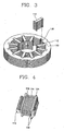
- Fig. 1 is a perspective view illustrating a conventional stator of a motor
- Fig. 2 is a perspective view illustrating the conventional stator on which a wiring PCB has been mounted.
- the conventional stator of the motor includes a stator core 110 and 112 formed by stacking a plurality of circular sheets to be insulated, a plurality of stator coils 114 mounted on the inner circumferential surface of the stator core 110 and 112 at predetermined intervals, and a wiring PCB 118 for wiring the stator coils 114.
- stator core 110 and 112 consists of a yoke 110 formed by stacking the circular ring-shaped sheets to be insulated, and teeth 112 mounted on the inner circumferential surface of the yoke 110 in the radial direction at predetermined intervals.
- Fig. 3 is a perspective view illustrating the conventional stator core
- Fig. 4 is a perspective view illustrating a conventional bobbin around which the stator coil has been wound.
- Fastening grooves 120 to which the teeth 112 are fastened are formed on the inner circumferential surface of the yoke 110 at predetermined intervals.
- the teeth 112 are formed by stacking a plurality of sheets, and fixed to the yoke 110, by inserting their one-side portions into the fastening grooves 120 of the yoke 110.
- Bobbins 124 around which the stator coils 114 are wound are fixed to the outer circumferential surfaces of the teeth 112.
- the bobbins 124 are made of insulators.
- the stator coils 114 are wound around the outer circumferential surfaces of the bobbins 124, and through holes 126 into which the teeth 112 are inserted are formed on the inner circumferential surfaces thereof.
- two connection pins to which both ends of the stator coil 114 are connected respectively are mounted on each of the bobbins 124.
- the wiring PCB 118 is disposed on one-side surface of the yoke 110.
- the connection pins 128 mounted on each bobbin 124 are connected to the wiring PCB 118 by soldering.
- the stator coils 114 are electrically connected by circuit patterns 130 formed on the wiring PCB 118.
- the stator coils 114 are wound around the plurality of bobbins 124, respectively.
- the teeth 112 are inserted into the through holes 126 of the bobbins 124 around which the stator coils 114 have been wound.
- the teeth 112 inserted into the bobbins 124 are fastened to the fastening holes 120 of the circular yoke 110 formed by stacking the plurality of sheets.
- the connection pins 128 of the bobbins 124 to which the stator coils 114 are connected are connected to the wiring PCB 118 by soldering.
- the stator coils must be wired after mounted on the stator core.
- the conventional stator of the motor requires the wiring PCB for wiring the stator coils, which increases a number of components, an assembly time and manufacturing expenses.
- JP-A-11 089 128 discloses a stator assembly having bobbins fixed to the inner circumferential surface of the stator core and connected to each other, and stator coils wound around the outer circumferential surfaces of the bobbins to be connected to each other.
- An object of the present invention is to provide a stator of a motor which can reduce an assembly time by omitting a process for wiring stator coils by rotatably connecting bobbins, so that the stator coils can be wound around the bobbins to connect the bobbins, and which can reduce a number of components and manufacturing expenses by omitting a wiring PCB, and a method for manufacturing the same.
- Another object of the present invention is to provide a stator of a motor which can cut down manufacturing expenses by reducing a waste amount of sheets composing a circular yoke, by forming a plurality of segments and assembling the segments into the circular yoke, and a method for manufacturing the same
- the present invention provides a stator of a motor as set out in claim 1. Embodiments of such stator are set out in claims 2-7.
- a method for manufacturing a stator of a motor is defined in claims 8-11.
- Fig. 5 is a perspective view illustrating a stator of a motor in accordance with the present invention.
- the stator of the motor includes a stator core 14 and 16 consisting of a yoke 14 formed by stacking a plurality of sheets 10 and 12, and a plurality of teeth 16 mounted on the inner circumferential surface of the yoke 14 in the radial direction, bobbins 18 fixed to the teeth 16 respectively and rotatably connected to each other, and stator coils 20 wound around the outer circumferential surfaces of the bobbins 18 to be connected to each other.
- fastening grooves 22 to which the teeth 16 are fastened are formed on the inner circumferential surface of the yoke 14 at predetermined intervals.
- the sheets 10 and 12 of the yoke 14 are comprised of a few segments assembled into a circular ring shape. That is, for example, the sheets 10 and 12 of the yoke 14 are comprised of semicircular first segments 10 and second segments 12, and both ends of the first and second segments 10 and 12 are fastened to compose circular rings.
- protrusions 24 and grooves 26 are formed at both ends of the first and second segments 10 and 12.
- the first and second segments 10 and 12 are connected to each other by inserting the protrusions 24 into the grooves 26.
- the yoke 14 consists of the plurality of segments, more yokes 14 can be formed with the same material than when the circular yokes are formed in a single body, which reduces the unit cost of production.
- fastening protrusions 30 inserted into the fastening grooves 22 formed on the inner circumferential surface of the yoke 14 are formed at one side portions of the teeth 16, and pole shoes 32 extended in the circumferential direction of the yoke 14 are formed at the other side portions of the teeth 16.
- neck units 34 reduced in width are formed on the teeth 16, for preventing the fastening protrusions 30 from being disconnected from the fastening grooves 22.
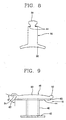
- each of the bobbins 18 includes a coil winding unit 40 around which the stator coil 20 is wound, an inside rib 42 formed inside the coil winding unit 40 to contact the pole shoe 32 of the tooth 16, an outside rib 44 formed outside the coil winding unit 40 to contact the inner circumferential surface of the yoke 14, and a hinge connection unit 46 formed at the upper portion of the outside rib 44, for rotatably connecting the bobbins 18.
- Each of the hinge connection units 46 includes a support unit 50 formed at the upper portion of the outside rib 44 and protruded by a predetermined width, a hinge groove 54 formed at one side end of the support unit 50, and a hinge protrusion 52 formed at the other side end of the support unit 50, and rotatably inserted into the hinge groove 54.
- the support units 50 are protruded from the upper portions of the outside ribs 44 in the forward direction by a predetermined width, for reinforcing rigidity.
- the hinge grooves 54 are circular grooves having their one-side portions opened.
- the hinge protrusions 52 are rotatably inserted into the hinge grooves 54.
- an open angle ⁇ of the hinge grooves 54 is equal to or smaller than 180° in order to prevent separation of the hinge protrusions 52.
- the hinge protrusions 52 are formed in a circular shape, inserted into the hinge grooves 54, and rotated within a predetermined range.
- the rotation range of the hinge protrusions 52 inserted into the hinge grooves 54 is set between 160 and 200°.
- contact surfaces 60 and 62 having a predetermined inclination angle are formed at both ends of the support units 50, so that the bobbins 18 can contact and support each other when forming a circular shape.
- the hinge connection units 46 are formed in a multiple number in order to reinforce connection rigidity of the bobbins 18. Most preferably, three hinge connection units 46 are provided.
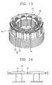
- the plurality of segments of Figs. 6 and 7 are assembled and stacked to compose the circular yoke 14. That is, the yoke 14 is formed by inserting the protrusions 24 formed on the first segments 10 into the grooves 26 formed on the second segments 12 to compose the circular sheets, and stacking the plurality of sheets.
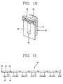
- the plurality of bobbins 18 are connected to each other and arranged in a straight line shape. That is, the bobbins 18 are arranged in a straight line shape by inserting the hinge protrusions 52 into the hinge grooves 54, and the stator coils 20 are wound around the bobbins 18, respectively. Since the bobbins 18 are arranged in a straight line shape, the stator coils 20 are wound around the bobbins 18 in the arrangement order and connected to each other.
- the teeth 16 are inserted into the bobbins 18, and the bobbins 18 are rotated to compose a circular shape.
- the fastening protrusions 30 of the teeth 16 are inserted into the fastening grooves 22 formed on the inner circumferential surface of the yoke 14.
- assembly of the stator is finished.
- Fig. 14 is a partial side view illustrating another example of the hinge connection units of the bobbins in accordance with the present invention.
- connection ribs 72 are formed between the bobbins 70, for connecting the bobbins 70. That is, the connection ribs 72 are formed in a thin film shape and connected between outside ribs 74 of the bobbins 70, for wholly connecting the bobbins 70.
- the bobbins are rotatably connected to each other and arranged in a straight line shape, and the stator coils are sequentially wound around the bobbins.
- stator coils are wound around the bobbins to be connected to each other between the bobbins.
- stator coils wound around the bobbins need not be wired, which simplifies the assembly process.
- special components for wiring the stator coils are not necessary, thereby reducing a number of components and cutting down manufacturing expenses.
- the plurality of segments are assembled into the yoke, and thus scraps of the material are minimized in production, to cut down manufacturing expenses.
Landscapes
- Engineering & Computer Science (AREA)
- Power Engineering (AREA)
- Manufacturing & Machinery (AREA)
- Iron Core Of Rotating Electric Machines (AREA)
- Insulation, Fastening Of Motor, Generator Windings (AREA)
- Manufacture Of Motors, Generators (AREA)
Claims (11)
- Stator d'un moteur, comprenant :un noyau de stator (14, 16) formé par empilage d'une pluralité de feuilles (10, 12) ;une pluralité de bobines (18) fixées sur la surface circonférentielle intérieure du noyau de stator à des intervalles prédéterminés, et ayant des unités de raccordement à charnière (46) pour raccorder de manière rotative les bobines les unes aux autres ; etdes bobinages de stator (20) enroulés autour des surfaces circonférentielles extérieures des bobines à raccorder les unes aux autres,dans lequel chaque bobine comporte une unité d'enroulement de bobinage (40) autour de laquelle le bobinage de stator est enroulé et une nervure extérieure (44) formée à l'extérieur de l'unité d'enroulement de bobinage pour être en contact avec la surface circonférentielle intérieure du noyau de stator, et en ce que chaque unité de raccordement à charnière (46) comprend :- une unité de support (50) formée au niveau d'une partie axialement supérieure d'une nervure extérieure (44) et faisant saillie axialement d'une largeur prédéterminée ;- une rainure de charnière (54) formée au niveau d'une extrémité latérale de l'unité de support (50) ; et- une saillie de charnière (52) formée au niveau de l'autre extrémité latérale de l'unité de support, et insérée de manière à pouvoir tourner dans la rainure de charnière (54) d'une autre bobine (18).
- Stator selon la revendication 1, dans lequel le noyau de stator se compose d'une culasse en forme d'anneau circulaire (14) formée en empilant une pluralité de feuilles (10, 12), et de dents (16) montées sur la surface circonférentielle intérieure de la culasse dans la direction radiale, les bobines (18) étant respectivement montées sur les dents.
- Stator selon la revendication 2, dans lequel chaque feuille de la culasse (14) est divisée en une pluralité de feuilles (10, 12), et la pluralité de feuilles sont raccordées les unes aux autres en forme d'anneau circulaire.
- Stator selon la revendication 3, dans lequel chacune des feuilles est divisée en des premiers segments semi-circulaires (10) et des seconds segments (12), des saillies (24) et des rainures (26) sont formées aux deux extrémités des premiers et seconds segments, et les premiers et seconds segments sont attachés les uns aux autres en insérant les saillies dans les rainures.
- Stator selon la revendication 1, dans lequel chacune des bobines (18) comprend en outre une nervure intérieure (42) formée à l'intérieur de l'unité d'enroulement de bobinage.
- Stator selon la revendication 5, dans lequel les unités de raccordement à charnière (46) comprennent des nervures de raccordement raccordées entre les nervures extérieures (44) pour former un corps unique.
- Stator selon la revendication 6, dans lequel les nervures de raccordement sont flexibles pour que les bobines (18) puissent être mises en rotation réciproque.
- Procédé de fabrication d'un stator d'un moteur, comprenant les étapes consistant à :former une culasse circulaire (14) par empilage d'une pluralité de feuilles (10, 12) ;raccorder et agencer des bobines (18) dans une rangée, chaque bobine étant formée pour être fixée sur la surface intérieure de la culasse circulaire, et comportant une unité d'enroulement de bobinage (40) autour de laquelle un bobinage de stator (20) est enroulé, une nervure extérieure (44) formée à l'extérieur de l'unité d'enroulement de bobinage pour être en contact avec la surface circonférentielle intérieure de la culasse circulaire, et une unité de raccordement à charnière (46) pour raccorder de manière rotative les bobines les unes aux autres comprend :- une unité de support (50) formée au niveau d'une partie axialement supérieure de la nervure extérieure et faisant saillie axialement d'une largeur prédéterminée ;- une rainure de charnière (54) formée au niveau d'une extrémité latérale de l'unité de support ; et- une saillie de charnière (52) formée au niveau de l'autre extrémité latérale de l'unité de support, et insérée de manière à pouvoir tourner dans la rainure de charnière d'une autre bobine ;enrouler les bobinages de stator (20) autour des bobines agencées dans une rangée à raccorder les unes aux autres,faire tourner les bobines autour desquelles les bobinages de stator ont été enroulés pour former une forme circulaire, et insérer les dents (16), etmonter les dents sur la culasse.
- Procédé selon la revendication 8, dans lequel l'étape de formation de la culasse (14) comprend la formation de feuilles circulaires en assemblant une pluralité de segments (10, 12) et en empilant les feuilles.
- Procédé selon la revendication 8, dans lequel l'étape de raccordement des bobines (18) comprend l'agencement des bobines dans une forme en ligne droite en insérant des saillies de charnière (52) dans des nervures de charnière (54), et en enroulant les bobinages de stator (20) autour des bobines à raccorder les unes aux autres.
- Procédé selon la revendication 8, dans lequel l'étape de montage des dents (16) sur la culasse (14) comprend l'insertion des saillies de fixation (30) des dents dans des rainures de fixation (22) formées sur la surface circonférentielle intérieure de la culasse.
Applications Claiming Priority (2)
| Application Number | Priority Date | Filing Date | Title |
|---|---|---|---|
| KR2004022389 | 2004-03-31 | ||
| KR1020040022389A KR100595552B1 (ko) | 2004-03-31 | 2004-03-31 | 연결형 보빈, 이를 구비한 모터의 고정자 및 그 제조방법 |
Publications (3)
| Publication Number | Publication Date |
|---|---|
| EP1583201A2 EP1583201A2 (fr) | 2005-10-05 |
| EP1583201A3 EP1583201A3 (fr) | 2006-03-15 |
| EP1583201B1 true EP1583201B1 (fr) | 2011-03-09 |
Family
ID=34880353
Family Applications (1)
| Application Number | Title | Priority Date | Filing Date |
|---|---|---|---|
| EP05290669A Ceased EP1583201B1 (fr) | 2004-03-31 | 2005-03-25 | Stator de moteur et son procédé de fabrication |
Country Status (6)
| Country | Link |
|---|---|
| US (1) | US7253547B2 (fr) |
| EP (1) | EP1583201B1 (fr) |
| JP (1) | JP2005295784A (fr) |
| KR (1) | KR100595552B1 (fr) |
| CN (1) | CN100442634C (fr) |
| DE (1) | DE602005026742D1 (fr) |
Families Citing this family (37)
| Publication number | Priority date | Publication date | Assignee | Title |
|---|---|---|---|---|
| KR100600758B1 (ko) * | 2004-09-15 | 2006-07-19 | 엘지전자 주식회사 | 모터의 스테이터 및 그 제조방법 |
| US7518269B2 (en) * | 2005-03-18 | 2009-04-14 | Ls Industrial Systems Co., Ltd. | Actuator using permanent magnet |
| KR100677281B1 (ko) * | 2005-06-16 | 2007-02-02 | 엘지전자 주식회사 | 토로이달 권선 방식을 적용한 하이브리드 유도전동기 |
| KR101143994B1 (ko) * | 2006-03-09 | 2012-05-09 | 주식회사 동서전자 | 모터의 스테이터 |
| WO2008069360A2 (fr) * | 2006-12-06 | 2008-06-12 | Lg Electronics Inc. | Moteur |
| WO2008069361A2 (fr) * | 2006-12-06 | 2008-06-12 | Lg Electronics Inc. | Moteur |
| DE202006019091U1 (de) * | 2006-12-19 | 2008-04-24 | Ebm-Papst Mulfingen Gmbh & Co. Kg | Stator und Rotor zum Aufbau eines elektrischen Motors |
| DE102007038848A1 (de) * | 2007-08-16 | 2009-02-19 | Dorma Gmbh + Co. Kg | Spulenkörper für einen Linearmotor-Stator für eine automatische Tür |
| JP5021443B2 (ja) * | 2007-12-14 | 2012-09-05 | 日立オートモティブシステムズ株式会社 | 回転電機 |
| JP5215737B2 (ja) * | 2008-06-04 | 2013-06-19 | アスモ株式会社 | インシュレータ、ステータ及びステータの製造方法 |
| JP5237049B2 (ja) * | 2008-10-28 | 2013-07-17 | アスモ株式会社 | インシュレータ、ステータ及びステータの製造方法 |
| DE102008054520A1 (de) * | 2008-12-11 | 2010-06-17 | Robert Bosch Gmbh | Stator in einem Elektromotor |
| DE102008054523A1 (de) * | 2008-12-11 | 2010-06-17 | Robert Bosch Gmbh | Stator in einem Elektromotor |
| TWI396362B (zh) * | 2009-06-09 | 2013-05-11 | Sunonwealth Electr Mach Ind Co | 馬達定子及其製造方法 |
| BE1019030A5 (nl) * | 2009-08-03 | 2012-01-10 | Atlas Copco Airpower Nv | Turbocompressorsysteem. |
| US8319464B2 (en) * | 2009-08-18 | 2012-11-27 | U.S. Department Of Energy | Flux control and one-hundred and eighty degree core systems |
| KR101134969B1 (ko) * | 2009-11-19 | 2012-04-09 | 현대자동차주식회사 | 전기식 워터 펌프의 고정자 제작 방법 |
| US20110273041A1 (en) * | 2010-05-10 | 2011-11-10 | Huan-Ching Tseng | Electricity-generating device |
| KR101133922B1 (ko) * | 2010-09-08 | 2012-04-13 | 주식회사 아모텍 | 세그먼트형 스테이터의 제조방법 및 그를 이용한 스테이터 |
| US9762095B2 (en) * | 2010-12-13 | 2017-09-12 | Radam Motors, Llc | Stator used in an electrical motor or generator with low loss magnetic material and method of manufacturing a stator |
| US8847457B2 (en) * | 2011-04-22 | 2014-09-30 | Honda Motor Co., Ltd. | Rotary electric machine and method of manufacturing same |
| JP5733050B2 (ja) * | 2011-06-24 | 2015-06-10 | アイシン精機株式会社 | 回転電機のステータおよび回転電機 |
| US8587424B2 (en) | 2011-12-05 | 2013-11-19 | David Aberizk | Vehicle regenerative deceleration actuator and indicator system and method |
| EP2672609B1 (fr) * | 2012-06-04 | 2021-11-03 | Herng Shan Electronics Co., Ltd. | Structure de moteur triphasée |
| DE102012211468A1 (de) * | 2012-07-03 | 2014-01-09 | Robert Bosch Gmbh | Spulenträger mit integrierten Haltern für das Phasenisolationspapier |
| CN103587565B (zh) * | 2013-11-18 | 2015-11-25 | 南车株洲电机有限公司 | 一种嵌线滚盘装卸装置及安装拆卸方法 |
| JP2016059208A (ja) * | 2014-09-11 | 2016-04-21 | 日立オートモティブシステムズ株式会社 | 電動流体ポンプ |
| JP6672638B2 (ja) * | 2015-08-24 | 2020-03-25 | スズキ株式会社 | モータ |
| CN105141047B (zh) * | 2015-09-10 | 2018-02-16 | 孝感市元达新材料科技有限公司 | 包覆式定子铁芯及其加工方法 |
| KR101947872B1 (ko) | 2016-10-21 | 2019-02-13 | 현대자동차주식회사 | 고효율 모터 고정자 및 그 제조방법 |
| FR3064835B1 (fr) * | 2017-03-31 | 2020-01-17 | Moving Magnet Technologies | Stator pour machine electrique |
| DE102017206597A1 (de) * | 2017-04-19 | 2018-10-25 | Continental Automotive Gmbh | Polzahnmodul für eine elektrische Maschine, Aktivteil mit einem Polzahnmodul und elektrische Maschine |
| FR3069118B1 (fr) * | 2017-07-17 | 2020-10-02 | Liebherr Aerospace Toulouse | Moteur couple comprenant un support de bobinage des bobines statoriques et procede d'assemblage d'un tel moteur couple |
| KR102607118B1 (ko) * | 2017-10-10 | 2023-11-29 | 제로 이 테크놀로지스 엘엘씨 | 전기 기계의 냉각 및 안정화 시스템 및 방법 |
| DE102019125862A1 (de) * | 2019-09-25 | 2021-03-25 | Vacuumschmelze Gmbh & Co. Kg | Mehrteiliger Stator, elektrische Maschine sowie Verfahren zur Herstellung eines mehrteiligen Stators und einer elektrischen Maschine |
| DE102020212922B4 (de) | 2020-10-14 | 2022-08-25 | Vitesco Technologies Germany Gmbh | Stator für eine elektrische Maschine, Verfahren zur Herstellung eines Stators und elektrische Maschine |
| DE102021206643A1 (de) * | 2021-06-28 | 2022-12-29 | Robert Bosch Gesellschaft mit beschränkter Haftung | Isoliermaske für einen Stator, Stator, elektrische Maschine und Herstellungsverfahren für einen Stator |
Family Cites Families (19)
| Publication number | Priority date | Publication date | Assignee | Title |
|---|---|---|---|---|
| US4182026A (en) * | 1977-08-17 | 1980-01-08 | Vibrac Corporation | Electric motor manufacture |
| JP3171303B2 (ja) * | 1995-01-12 | 2001-05-28 | 株式会社三井ハイテック | 固定子用積層鉄心 |
| JP3680482B2 (ja) * | 1997-03-28 | 2005-08-10 | 松下電器産業株式会社 | 電動機の固定子構成部材、電動機の固定子、電動機の製造方法 |
| JP4005169B2 (ja) * | 1997-04-11 | 2007-11-07 | 東芝キヤリア株式会社 | 圧縮機 |
| JPH1189128A (ja) | 1997-09-12 | 1999-03-30 | Toshiba Corp | 電動機の固定子およびその製造方法 |
| JPH11178259A (ja) * | 1997-12-09 | 1999-07-02 | Matsushita Seiko Co Ltd | 電動機固定子とその製造方法 |
| JP3421251B2 (ja) * | 1998-08-21 | 2003-06-30 | ミネベア株式会社 | 回転電機及びそのボビン |
| US6081059A (en) * | 1999-04-21 | 2000-06-27 | Hsu; Chun-Pu | Outer-rotor electric motor having inner-stator formed by concentrically wrapping flattened stator elements on stator core |
| JP2000317861A (ja) | 1999-05-13 | 2000-11-21 | Asuka:Kk | 簡易型電動ステープラ |
| TW508891B (en) * | 2000-02-21 | 2002-11-01 | Misubishi Electric Corp | Stator iron core of electric motor, manufacturing method thereof, electric motor, and compresor |
| TW490916B (en) | 2000-05-26 | 2002-06-11 | Jiun-Fu Shiu | Assembly-type external motor stator |
| JP3704029B2 (ja) | 2000-07-24 | 2005-10-05 | 三菱電機株式会社 | 始動用電動機の固定子 |
| JP2002176753A (ja) * | 2000-12-07 | 2002-06-21 | Matsushita Electric Ind Co Ltd | 電動機固定子の製造方法及びその固定子 |
| EP1276206A1 (fr) | 2001-07-10 | 2003-01-15 | Chun-Pu Hsu | Bobine d'enroulement de stator pour constituer une structure de stator fermée annulairement du coté de l'entrefer |
| JP2003244883A (ja) * | 2002-02-19 | 2003-08-29 | Hitachi Ltd | 外転型モータ及びそのモータ固定子の組立方法 |
| KR100454556B1 (ko) * | 2002-05-09 | 2004-11-05 | 주식회사 미크로닉 | 세그먼트형 스테이터 코어를 이용한 비엘디씨 모터용스테이터 및 그의 제조방법과 비엘디씨 모터 |
| US6555942B1 (en) * | 2002-05-10 | 2003-04-29 | Chun-Pu Hsu | Assembly type stator structure having flat wire wound coils |
| US7111380B2 (en) * | 2002-10-31 | 2006-09-26 | Emerson Electric Co. | Method for forming an annular stator assembly |
| US7414347B2 (en) * | 2004-03-23 | 2008-08-19 | Emerson Electric Co. | End cap for segmented stator |
-
2004
- 2004-03-31 KR KR1020040022389A patent/KR100595552B1/ko not_active Expired - Fee Related
- 2004-11-12 US US10/985,936 patent/US7253547B2/en not_active Expired - Fee Related
- 2004-11-26 JP JP2004342344A patent/JP2005295784A/ja active Pending
- 2004-12-06 CN CNB2004101006590A patent/CN100442634C/zh not_active Expired - Fee Related
-
2005
- 2005-03-25 EP EP05290669A patent/EP1583201B1/fr not_active Ceased
- 2005-03-25 DE DE602005026742T patent/DE602005026742D1/de not_active Expired - Lifetime
Also Published As
| Publication number | Publication date |
|---|---|
| CN1677792A (zh) | 2005-10-05 |
| JP2005295784A (ja) | 2005-10-20 |
| US20050218749A1 (en) | 2005-10-06 |
| US7253547B2 (en) | 2007-08-07 |
| KR100595552B1 (ko) | 2006-07-03 |
| KR20050096723A (ko) | 2005-10-06 |
| CN100442634C (zh) | 2008-12-10 |
| EP1583201A3 (fr) | 2006-03-15 |
| EP1583201A2 (fr) | 2005-10-05 |
| DE602005026742D1 (de) | 2011-04-21 |
Similar Documents
| Publication | Publication Date | Title |
|---|---|---|
| EP1583201B1 (fr) | Stator de moteur et son procédé de fabrication | |
| JP5333996B2 (ja) | 固定子およびこれを用いた回転電機 | |
| US6580193B2 (en) | Rotary electric machine and manufacturing method therefor | |
| US6700295B2 (en) | Rotor of electric motor and manufacturing method thereof | |
| US20120080976A1 (en) | Stator for electrical rotating machine | |
| US20050073211A1 (en) | Laminated body of motor and manufacturing method thereof | |
| JP4444639B2 (ja) | 回転電機のステータ及びその製造方法 | |
| JP2007068310A (ja) | 回転機の積層巻きコア | |
| JP2010154701A (ja) | 回転電機用ターミナル | |
| CN101728887A (zh) | 用于电机线圈的配线部件 | |
| JP6979464B2 (ja) | 回転電機の固定子 | |
| US7098565B2 (en) | Core-coil assembly of motor and manufacturing method thereof | |
| JPH06311675A (ja) | 分割形環状コア | |
| JP4076837B2 (ja) | インシュレータ及び回転磁界型電動機 | |
| JPWO2016208629A1 (ja) | 回転電機の固定子、回転電機、回転電機の固定子の製造方法、回転電機の製造方法 | |
| JP3913713B2 (ja) | インシュレータ及びその製造方法 | |
| WO2022249525A1 (fr) | Isolateur, stator, machine dynamoélectrique, procédé de fabrication d'un stator et procédé de fabrication d'une machine dynamoélectrique | |
| JP4297929B2 (ja) | モータ及びモータの製造方法 | |
| JP4321144B2 (ja) | コンデンサ電動機の固定子およびその製造方法 | |
| WO2019235071A1 (fr) | Stator de machine électrique rotative et machine électrique rotative | |
| EP4044402B1 (fr) | Moteur | |
| JP2021100290A (ja) | 回転電機のステータ、回転電機、及び巻枠の製造方法 | |
| JP4018474B2 (ja) | ステータ及び回転電動機 | |
| WO2017217271A1 (fr) | Stator pour machine électrique rotative | |
| JP2009100625A (ja) | ステータおよび回転電機 |
Legal Events
| Date | Code | Title | Description |
|---|---|---|---|
| PUAI | Public reference made under article 153(3) epc to a published international application that has entered the european phase |
Free format text: ORIGINAL CODE: 0009012 |
|
| 17P | Request for examination filed |
Effective date: 20050405 |
|
| AK | Designated contracting states |
Kind code of ref document: A2 Designated state(s): AT BE BG CH CY CZ DE DK EE ES FI FR GB GR HU IE IS IT LI LT LU MC NL PL PT RO SE SI SK TR |
|
| AX | Request for extension of the european patent |
Extension state: AL BA HR LV MK YU |
|
| PUAL | Search report despatched |
Free format text: ORIGINAL CODE: 0009013 |
|
| AK | Designated contracting states |
Kind code of ref document: A3 Designated state(s): AT BE BG CH CY CZ DE DK EE ES FI FR GB GR HU IE IS IT LI LT LU MC NL PL PT RO SE SI SK TR |
|
| AX | Request for extension of the european patent |
Extension state: AL BA HR LV MK YU |
|
| AKX | Designation fees paid |
Designated state(s): DE FR GB IT |
|
| 17Q | First examination report despatched |
Effective date: 20070312 |
|
| GRAP | Despatch of communication of intention to grant a patent |
Free format text: ORIGINAL CODE: EPIDOSNIGR1 |
|
| GRAS | Grant fee paid |
Free format text: ORIGINAL CODE: EPIDOSNIGR3 |
|
| GRAA | (expected) grant |
Free format text: ORIGINAL CODE: 0009210 |
|
| AK | Designated contracting states |
Kind code of ref document: B1 Designated state(s): DE FR GB IT |
|
| REG | Reference to a national code |
Ref country code: GB Ref legal event code: FG4D |
|
| REF | Corresponds to: |
Ref document number: 602005026742 Country of ref document: DE Date of ref document: 20110421 Kind code of ref document: P |
|
| REG | Reference to a national code |
Ref country code: DE Ref legal event code: R096 Ref document number: 602005026742 Country of ref document: DE Effective date: 20110421 |
|
| PLBE | No opposition filed within time limit |
Free format text: ORIGINAL CODE: 0009261 |
|
| STAA | Information on the status of an ep patent application or granted ep patent |
Free format text: STATUS: NO OPPOSITION FILED WITHIN TIME LIMIT |
|
| 26N | No opposition filed |
Effective date: 20111212 |
|
| REG | Reference to a national code |
Ref country code: DE Ref legal event code: R097 Ref document number: 602005026742 Country of ref document: DE Effective date: 20111212 |
|
| REG | Reference to a national code |
Ref country code: FR Ref legal event code: PLFP Year of fee payment: 11 |
|
| REG | Reference to a national code |
Ref country code: FR Ref legal event code: PLFP Year of fee payment: 12 |
|
| REG | Reference to a national code |
Ref country code: FR Ref legal event code: PLFP Year of fee payment: 13 |
|
| REG | Reference to a national code |
Ref country code: FR Ref legal event code: PLFP Year of fee payment: 14 |
|
| PGFP | Annual fee paid to national office [announced via postgrant information from national office to epo] |
Ref country code: DE Payment date: 20200211 Year of fee payment: 16 Ref country code: GB Payment date: 20200213 Year of fee payment: 16 Ref country code: IT Payment date: 20200312 Year of fee payment: 16 |
|
| PGFP | Annual fee paid to national office [announced via postgrant information from national office to epo] |
Ref country code: FR Payment date: 20200213 Year of fee payment: 16 |
|
| REG | Reference to a national code |
Ref country code: DE Ref legal event code: R119 Ref document number: 602005026742 Country of ref document: DE |
|
| GBPC | Gb: european patent ceased through non-payment of renewal fee |
Effective date: 20210325 |
|
| PG25 | Lapsed in a contracting state [announced via postgrant information from national office to epo] |
Ref country code: FR Free format text: LAPSE BECAUSE OF NON-PAYMENT OF DUE FEES Effective date: 20210331 Ref country code: GB Free format text: LAPSE BECAUSE OF NON-PAYMENT OF DUE FEES Effective date: 20210325 Ref country code: DE Free format text: LAPSE BECAUSE OF NON-PAYMENT OF DUE FEES Effective date: 20211001 |
|
| PG25 | Lapsed in a contracting state [announced via postgrant information from national office to epo] |
Ref country code: IT Free format text: LAPSE BECAUSE OF NON-PAYMENT OF DUE FEES Effective date: 20210325 |