EP1580380A2 - Treibstangenbeschlag - Google Patents
Treibstangenbeschlag Download PDFInfo
- Publication number
- EP1580380A2 EP1580380A2 EP05101647A EP05101647A EP1580380A2 EP 1580380 A2 EP1580380 A2 EP 1580380A2 EP 05101647 A EP05101647 A EP 05101647A EP 05101647 A EP05101647 A EP 05101647A EP 1580380 A2 EP1580380 A2 EP 1580380A2
- Authority
- EP
- European Patent Office
- Prior art keywords
- control
- drive rod
- section
- locking pin
- wing
- Prior art date
- Legal status (The legal status is an assumption and is not a legal conclusion. Google has not performed a legal analysis and makes no representation as to the accuracy of the status listed.)
- Withdrawn
Links
- 238000009423 ventilation Methods 0.000 claims description 24
- 235000003332 Ilex aquifolium Nutrition 0.000 description 1
- 241000209027 Ilex aquifolium Species 0.000 description 1
- 238000010276 construction Methods 0.000 description 1
Images


Classifications
-
- E—FIXED CONSTRUCTIONS
- E05—LOCKS; KEYS; WINDOW OR DOOR FITTINGS; SAFES
- E05C—BOLTS OR FASTENING DEVICES FOR WINGS, SPECIALLY FOR DOORS OR WINDOWS
- E05C9/00—Arrangements of simultaneously actuated bolts or other securing devices at well-separated positions on the same wing
- E05C9/18—Details of fastening means or of fixed retaining means for the ends of bars
- E05C9/1825—Fastening means
- E05C9/1875—Fastening means performing pivoting movements
- E05C9/1883—Fastening means performing pivoting movements pivotally mounted on the actuation bar
-
- E—FIXED CONSTRUCTIONS
- E05—LOCKS; KEYS; WINDOW OR DOOR FITTINGS; SAFES
- E05C—BOLTS OR FASTENING DEVICES FOR WINGS, SPECIALLY FOR DOORS OR WINDOWS
- E05C9/00—Arrangements of simultaneously actuated bolts or other securing devices at well-separated positions on the same wing
- E05C9/06—Arrangements of simultaneously actuated bolts or other securing devices at well-separated positions on the same wing with three or more sliding bars
- E05C9/063—Arrangements of simultaneously actuated bolts or other securing devices at well-separated positions on the same wing with three or more sliding bars extending along three or more sides of the wing or frame
- E05C9/066—Locks for windows or doors specially adapted for tilt and turn
-
- E—FIXED CONSTRUCTIONS
- E05—LOCKS; KEYS; WINDOW OR DOOR FITTINGS; SAFES
- E05D—HINGES OR SUSPENSION DEVICES FOR DOORS, WINDOWS OR WINGS
- E05D15/00—Suspension arrangements for wings
- E05D15/48—Suspension arrangements for wings allowing alternative movements
- E05D15/52—Suspension arrangements for wings allowing alternative movements for opening about a vertical as well as a horizontal axis
- E05D15/5205—Suspension arrangements for wings allowing alternative movements for opening about a vertical as well as a horizontal axis with horizontally-extending checks
-
- E—FIXED CONSTRUCTIONS
- E05—LOCKS; KEYS; WINDOW OR DOOR FITTINGS; SAFES
- E05D—HINGES OR SUSPENSION DEVICES FOR DOORS, WINDOWS OR WINGS
- E05D15/00—Suspension arrangements for wings
- E05D15/48—Suspension arrangements for wings allowing alternative movements
- E05D15/52—Suspension arrangements for wings allowing alternative movements for opening about a vertical as well as a horizontal axis
- E05D15/5214—Corner supports
-
- E—FIXED CONSTRUCTIONS
- E05—LOCKS; KEYS; WINDOW OR DOOR FITTINGS; SAFES
- E05C—BOLTS OR FASTENING DEVICES FOR WINGS, SPECIALLY FOR DOORS OR WINDOWS
- E05C17/00—Devices for holding wings open; Devices for limiting opening of wings or for holding wings open by a movable member extending between frame and wing; Braking devices, stops or buffers, combined therewith
-
- E—FIXED CONSTRUCTIONS
- E05—LOCKS; KEYS; WINDOW OR DOOR FITTINGS; SAFES
- E05D—HINGES OR SUSPENSION DEVICES FOR DOORS, WINDOWS OR WINGS
- E05D3/00—Hinges with pins
- E05D3/02—Hinges with pins with one pin
- E05D3/022—Hinges with pins with one pin allowing an additional lateral movement, e.g. for sealing
-
- E—FIXED CONSTRUCTIONS
- E05—LOCKS; KEYS; WINDOW OR DOOR FITTINGS; SAFES
- E05Y—INDEXING SCHEME ASSOCIATED WITH SUBCLASSES E05D AND E05F, RELATING TO CONSTRUCTION ELEMENTS, ELECTRIC CONTROL, POWER SUPPLY, POWER SIGNAL OR TRANSMISSION, USER INTERFACES, MOUNTING OR COUPLING, DETAILS, ACCESSORIES, AUXILIARY OPERATIONS NOT OTHERWISE PROVIDED FOR, APPLICATION THEREOF
- E05Y2900/00—Application of doors, windows, wings or fittings thereof
- E05Y2900/10—Application of doors, windows, wings or fittings thereof for buildings or parts thereof
- E05Y2900/13—Type of wing
- E05Y2900/132—Doors
-
- E—FIXED CONSTRUCTIONS
- E05—LOCKS; KEYS; WINDOW OR DOOR FITTINGS; SAFES
- E05Y—INDEXING SCHEME ASSOCIATED WITH SUBCLASSES E05D AND E05F, RELATING TO CONSTRUCTION ELEMENTS, ELECTRIC CONTROL, POWER SUPPLY, POWER SIGNAL OR TRANSMISSION, USER INTERFACES, MOUNTING OR COUPLING, DETAILS, ACCESSORIES, AUXILIARY OPERATIONS NOT OTHERWISE PROVIDED FOR, APPLICATION THEREOF
- E05Y2900/00—Application of doors, windows, wings or fittings thereof
- E05Y2900/10—Application of doors, windows, wings or fittings thereof for buildings or parts thereof
- E05Y2900/13—Type of wing
- E05Y2900/148—Windows
Definitions
- the invention relates to a drive rod fitting for Opening and closing a pivotable against a frame Wing of a window, a French window or the like with a driven, on the wing or the Frame to be arranged drive rod, with one on each opposing component to be arranged strike plate, with a drive arm driven by the drive rod, with a locking pin arranged on the control arm, arranged with at least one in the strike plate Bag for holding and behind the lock pin in a night ventilation position and with a in a Control plate arranged control groove for receiving two with the control arm connected control pin, one of which is connected to the drive rod, wherein the control groove a pointing in the direction of movement of the drive rod first section and join the first section adjoining, slanted towards the first section second section has and where is the strike plate a recess for taking out the locking pin in having a rotational position and / or a tilted position.
- Such a drive rod fitting is for example off DE 1 259 222 A is known.
- the striking plate of the espagnolette fitting has one of a recess to the Pocket guided groove in which the on the control arm arranged arranged locking pin to move along. Of the Control arm is over in the first section of the control groove driven by the drive rod control pin guided longitudinally displaceable. If the second control pin enters the second section of the control groove is by the inclination of the second section of the control arm pivoted and the wing pushed away from the frame. Is the second control pin at the end of second section, the locking pin enters the pocket of the striking plate. In this night ventilation position the wing is slightly away from the frame. In a closed position is the locking pin for example, in the middle of the groove.
- the espagnolette fitting therefore requires more locking pins and Strike plates to lock the wing in the frame.
- the disadvantage here is that a reliable Locking of the wing in the closed position particularly high construction effort requires.
- Farther is the switching sequence with which the closed position, the Rotary position and the night ventilation position activated are determined by the shape of the groove of the strike plate.
- the invention is based on the problem, a drive rod fitting of the type mentioned at the beginning, that he in the night ventilation position a large Distance of the sash from the frame allows and in Night ventilation position and closed position opposite the wing Reliably locked to the frame.
- control groove one in the direction of movement of the drive rod pointing and offset to the first section arranged third section has and that in the night ventilation position one of the control pins in the first and the second control pin is guided in the third section, and that the strike plate a the locking pin in Having closed position receiving pocket.
- the equipped with the espagnolette invention Wing is reliable in the night ventilation position locked in the frame when the second section Seen in the direction of movement of the drive rod between the first section and the third section is.
- this has the strike plate put two bags on each other, taking in one of the pockets Locking pin in the night ventilation position and in the other pocket of the locking pin in the closed position located. Is the locking pin between The two pockets, he lets himself from the strike plate remove.
- the drive rod fitting according to the invention can in this position of the locking pin the rotational position and / or allow the tilting position of the wing.
- control plate with the control groove points according to another advantageous development of the invention a particularly high stability on when the third section from the first and second sections through a bridge is disconnected.
- the device according to the invention requires very few components to be mounted when the control panel part a cover plate covering the drive rod is.
- a further enlargement of the of the control groove and the Length of the control arm fixed distance of the wing from the frame in the night ventilation position can be according to another advantageous embodiment of the invention Easy to reach when the pockets of the strike plate against each other transversely to the direction of movement of Locking pin are offset.
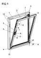
- Figure 1 shows a window with a mounted on a frame 1 Wing 2 and with a drive rod fitting 3 in a tilted position, wherein the wing 1 to a horizontal Tilting axis 4 is shown tilted.
- the espagnolette fitting 3 is driven by a handle 5.
- the Wing 2 can be about a vertical axis of rotation 6 in one Turn the rotary position.
- the wing 2 can be in lock a closed position lying in the frame 1 and move to a night ventilation position, in the the plane of the wing 2 a gap far from the frame. 1 is removed.
- the handle 5 has several positions, where Z is the closed position, D is the rotational position, with K the tilted position and with L the night ventilation position of the espagnolette fitting 3 is marked.
- the wing 2 of a Ausstellschere 7 held. At the intersection of the axes 4, 6, the window has a corner bearing 8.
- the Ausstellschere 7 is articulated via a pivot bearing 9 on the frame 1, while the wing 2 at its lower horizontal Holm has a tilting bearing 10.
- the espagnolette fitting 3 has a drivable by the handle 5 and in Figure 2 shown drive rod 11. About the drive rod 11 are several locking pins 12 drivable.
- the locking pin 12th are frame-mounted strike plates 13 opposite, which the Locking pin 12 in the closed position and the night ventilation position engage positively behind.
- Figure 2 shows in a sectional view through the Espagnolette fitting 3 in the region of one of the locking pins 12, that the locking pin 12 is arranged on a control arm 14 is.
- the control arm 14 is provided with two control pins 15, 16, which in a control groove 17 of a control plate 18 penetrate.
- the control plate 18 is part of a the drive rod 11 covering cuff rail 19.
- a first control pin 15 is exclusively in the control groove 17 guided while the second control pin 16 the Control plate 18 penetrates through the control groove 17 and is connected to the drive rod 11. This will be at a Drive the drive rod 11 of the lock pin 12 is moved and the control arm 14 via the control pins 15, 16 guided in the control groove 17.
- Figure 3 shows in a view from above on the espagnolette fitting 3 of Figure 2, that the control groove 17 a pointing in the direction of movement of the drive rod 11 first section 20 and join the first section 20 subsequent and opposite to the direction of movement the drive rod 11 inclined second section 21 for guiding the first control pin 15 has. Furthermore, the cam 17 has an offset to the first Section 20 arranged third section 22 to Guide the second, connected to the drive rod 11 Control pin 16. Between the second section 21 and the third section 22 is the control groove 17 of a Bridge 23 interrupted. The control pins 15, 16 are located each at the left-hand end of the first and third Section 20, 22 of the cam 17.
- FIG. 4 shows the drive rod fitting 3 in the region of Locking pin 12 in the tilt or the rotational position. It can be seen that the first control pin 15th in the second section 21 of the cam 17 is moved. Compared to the gap ventilation position shown in FIG is the control arm 14 to the direction of movement of Driving rod 11 inclined towards. The locking pin 12 is located in the region of the recess 26 of the striking plate 13. Thus, the wing 2 can be removed from the frame 1.
- the espagnolette fitting 3 preferably has several Holmen of the window distributed strike plates arranged 13th and locking pin 12, as described in Figures 2 to 5 are. Furthermore, the espagnolette fitting has 3 well-known and not shown control means for controlling the Ausstellschere 7 for selecting the tilt position and the rotational position.
- FIG. 6 shows the corner bearing 8 from FIG. 1 in one Sectional view along the line VI - VI.
- the corner warehouse 8 has on the axis of rotation 6 a pivot pin 27, on one mounted on the wing 2 sleeve 28 rotatably mounted is. Furthermore, the corner bearing 8 has a vertical pointing to the plane axis 29 which a tilting of the Wing 2 allows the tilting axis 4 shown in Figure 1.
- the Longitudinal guide 31 allows movement of the wing second away from the frame 1 by the distance a in the night ventilation position.
Landscapes
- Engineering & Computer Science (AREA)
- Mechanical Engineering (AREA)
- Specific Sealing Or Ventilating Devices For Doors And Windows (AREA)
- Window Of Vehicle (AREA)
- Power-Operated Mechanisms For Wings (AREA)
Abstract
Description
- Fig. 1
- ein Fenster mit einem erfindungsgemäßen Treibstangenbeschlag,
- Fig. 2
- eine Schnittdarstellung durch den Treibstangenbeschlag aus Figur 1 entlang der Linie II - II im Bereich eines auf einem Steuerarm angeordneten Schließzapfens,
- Fig. 3
- eine Draufsicht auf den Schließzapfen mit dem Steuerarm in einer Spaltlüftungsstellung,
- Fig. 4
- eine Draufsicht auf den Schließzapfen mit dem Steuerarm in einer Dreh- oder Kippstellung,
- Fig. 5
- eine Draufsicht auf den Schließzapfen mit dem Steuerarm in einer Schließstellung,
- Fig. 6
- eine Schnittdarstellung durch ein Ecklager des Treibstangenbeschlages aus Figur 1 entlang der Linie VI - VI.
Claims (6)
- Treibstangenbeschlag zum Öffnen und Schließen eines gegen einen Rahmen schwenkbaren Flügels eines Fensters, einer Fenstertür oder dergleichen mit einer angetriebenen, an dem Flügel oder dem Rahmen anzuordnenden Treibstange, mit einem auf dem jeweils gegenüberliegenden Bauteil anzuordnenden Schließblech, mit einem von der Treibstange antreibbaren Steuerarm, mit einem auf dem Steuerarm angeordneten Schließzapfen, mit zumindest einer in dem Schließblech angeordneten Tasche zur Aufnahme und Hintergreifung des Schließzapfens in einer Spaltlüftungsstellung und mit einer in einer Steuerplatte angeordneten Steuernut zur Aufnahme zweier mit dem Steuerarm verbundener Steuerzapfen, von denen einer mit der Treibstange verbunden ist, wobei die Steuernut einen in Bewegungsrichtung der Treibstange weisenden ersten Abschnitt und einen sich an den ersten Abschnitt anschließenden, gegenüber dem ersten Abschnitt schräg gestellten zweiten Abschnitt hat und wobei das Schließblech eine Ausnehmung zur Herausführung des Schließzapfens in einer Drehstellung und/oder einer Kippstellung aufweist, dadurch gekennzeichnet, dass die Steuernut (17) einen in Bewegungsrichtung der Treibstange (11) weisenden und versetzt zu dem ersten Abschnitt (20) angeordneten dritten Abschnitt (22) hat und dass in der Spaltlüftungsstellung einer der Steuerzapfen (15) in dem ersten Abschnitt (20) und der zweite Steuerzapfen (16) in dem dritten Abschnitt (22) geführt ist, und dass das Schließblech (13) eine den Schließzapfen (12) in Schließstellung aufnehmende Tasche (24) aufweist.
- Treibstangenbeschlag nach Anspruch 1, dadurch gekennzeichnet, dass der zweite Abschnitt (21) in Bewegungsrichtung der Treibstange (11) gesehen zwischen dem ersten Abschnitt (20) und dem dritten Abschnitt (22) angeordnet ist.
- Treibstangenbeschlag nach Anspruch 1 oder 2, dadurch gekennzeichnet, dass der dritte Abschnitt (22) von dem ersten und dem zweiten Abschnitt (20, 21) durch einen Steg (23) getrennt ist.
- Treibstangenbeschlag nach zumindest einem der vorhergehenden Ansprüche, dadurch gekennzeichnet, dass die Steuerplatte (18) Teil einer die Treibstange (11) abdeckenden Stulpschiene (19) ist.
- Treibstangenbeschlag nach zumindest einem der vorhergehenden Ansprüche, dadurch gekennzeichnet, dass die Taschen (24, 25) des Schließblechs (23) gegeneinander quer zur Bewegungsrichtung des Schließzapfens (12) versetzt sind.
- Treibstangenbeschlag nach zumindest einem der vorhergehenden Ansprüche, dadurch gekennzeichnet, dass ein im Schnittpunkt einer Drehachse (6) und einer Kippachse (4) angeordnetes Ecklager (8) senkrecht zu der Drehachse (6) und der Kippachse (4) eine Längsführung (31) für ein zur Halterung des Flügels (2) vorgesehenes Bauteil hat.
Applications Claiming Priority (2)
| Application Number | Priority Date | Filing Date | Title |
|---|---|---|---|
| DE200410014509 DE102004014509A1 (de) | 2004-03-25 | 2004-03-25 | Treibstangenbeschlag |
| DE102004014509 | 2004-03-25 |
Publications (2)
| Publication Number | Publication Date |
|---|---|
| EP1580380A2 true EP1580380A2 (de) | 2005-09-28 |
| EP1580380A3 EP1580380A3 (de) | 2009-11-18 |
Family
ID=34854034
Family Applications (1)
| Application Number | Title | Priority Date | Filing Date |
|---|---|---|---|
| EP05101647A Withdrawn EP1580380A3 (de) | 2004-03-25 | 2005-03-03 | Treibstangenbeschlag |
Country Status (2)
| Country | Link |
|---|---|
| EP (1) | EP1580380A3 (de) |
| DE (1) | DE102004014509A1 (de) |
Cited By (4)
| Publication number | Priority date | Publication date | Assignee | Title |
|---|---|---|---|---|
| EP1939387A3 (de) * | 2006-12-29 | 2010-10-06 | GSG INTERNATIONAL S.p.A. | Kippfenstereinheit |
| CN105569473A (zh) * | 2016-01-06 | 2016-05-11 | 立兴杨氏实业(深圳)有限公司 | 锁扣装置 |
| CN105649443A (zh) * | 2016-01-06 | 2016-06-08 | 立兴杨氏实业(深圳)有限公司 | 锁扣装置 |
| WO2017117760A1 (zh) * | 2016-01-06 | 2017-07-13 | 立兴杨氏实业(深圳)有限公司 | 锁扣装置 |
Citations (3)
| Publication number | Priority date | Publication date | Assignee | Title |
|---|---|---|---|---|
| DE1259222B (de) | 1964-01-18 | 1968-01-18 | Jaeger Frank K G | Betaetigungsvorrichtung zum OEffnen und Schliessen eines um eine waagerechte Achse kippbaren oder klappbaren Fluegels, insbesondere von Kipp-Schwenkfluegelfenstern, -tueren od. dgl. |
| FR2220658A1 (en) | 1973-03-05 | 1974-10-04 | Ferco | Tightening device to give firm closure of windows - uses rollers moving in inclined grooves to apply required closing force |
| DE3043925C2 (de) | 1980-11-03 | 1994-09-29 | Winkhaus Fa August | Vorrichtung an einem Fenster zur Einstellung des Flügelrahmens in eine Spaltöffnungsstellung |
Family Cites Families (3)
| Publication number | Priority date | Publication date | Assignee | Title |
|---|---|---|---|---|
| DE1086146B (de) * | 1956-05-14 | 1960-07-28 | Otto Pregitzer & Co | Seitenverriegelung fuer Fenster- oder Tuerfluegel |
| DE1708412A1 (de) * | 1967-05-02 | 1971-05-13 | Hautau Baubeschlag | Ausstellvorrichtung fuer Dreh-Kippfluegel von Fenstern od. dgl. |
| DE10254537A1 (de) * | 2002-11-21 | 2004-06-03 | Aug. Winkhaus Gmbh & Co. Kg | Fenster oder Tür |
-
2004
- 2004-03-25 DE DE200410014509 patent/DE102004014509A1/de not_active Withdrawn
-
2005
- 2005-03-03 EP EP05101647A patent/EP1580380A3/de not_active Withdrawn
Patent Citations (3)
| Publication number | Priority date | Publication date | Assignee | Title |
|---|---|---|---|---|
| DE1259222B (de) | 1964-01-18 | 1968-01-18 | Jaeger Frank K G | Betaetigungsvorrichtung zum OEffnen und Schliessen eines um eine waagerechte Achse kippbaren oder klappbaren Fluegels, insbesondere von Kipp-Schwenkfluegelfenstern, -tueren od. dgl. |
| FR2220658A1 (en) | 1973-03-05 | 1974-10-04 | Ferco | Tightening device to give firm closure of windows - uses rollers moving in inclined grooves to apply required closing force |
| DE3043925C2 (de) | 1980-11-03 | 1994-09-29 | Winkhaus Fa August | Vorrichtung an einem Fenster zur Einstellung des Flügelrahmens in eine Spaltöffnungsstellung |
Cited By (5)
| Publication number | Priority date | Publication date | Assignee | Title |
|---|---|---|---|---|
| EP1939387A3 (de) * | 2006-12-29 | 2010-10-06 | GSG INTERNATIONAL S.p.A. | Kippfenstereinheit |
| CN105569473A (zh) * | 2016-01-06 | 2016-05-11 | 立兴杨氏实业(深圳)有限公司 | 锁扣装置 |
| CN105649443A (zh) * | 2016-01-06 | 2016-06-08 | 立兴杨氏实业(深圳)有限公司 | 锁扣装置 |
| WO2017117760A1 (zh) * | 2016-01-06 | 2017-07-13 | 立兴杨氏实业(深圳)有限公司 | 锁扣装置 |
| CN105649443B (zh) * | 2016-01-06 | 2017-09-22 | 立兴杨氏实业(深圳)有限公司 | 锁扣装置 |
Also Published As
| Publication number | Publication date |
|---|---|
| EP1580380A3 (de) | 2009-11-18 |
| DE102004014509A1 (de) | 2005-12-15 |
Similar Documents
| Publication | Publication Date | Title |
|---|---|---|
| EP1312742A2 (de) | Austellvorrichtung für einen Kipp-Flügel, insbesondere Dreh-Kipp-Flügel eines Fensters, einer Tür oder dergleichen, entsprechende Fenstereinrichtung und entsprechendes Verfahren zum motorischen und manuellen Kippen | |
| EP1580381B1 (de) | Treibstangenbeschlag | |
| EP1580380A2 (de) | Treibstangenbeschlag | |
| DE1816581B2 (de) | Fluegelverschlussvorrichtung fuer fenster, tueren o.dgl. | |
| EP1614844A2 (de) | Drehlagervorrichtung | |
| EP0531626B1 (de) | Beschlag für insb. zwangsweise kipp- und parallel abstellbare Flügel | |
| EP0246431B1 (de) | Ausstellvorrichtung für Kippflügel, insbesondere Drehkipp- oder auch Schiebekippflügel, von Fenstern, Türen od. dgl. | |
| DE2658626B2 (de) | Schaltsperre für Treibstangenbeschläge | |
| EP1321615B1 (de) | Drehkippfenster | |
| EP1715125A2 (de) | Drehkipp- bzw. Kippdrehfensterbeschlag mit Spaltlüftungsstellung | |
| EP0980951A2 (de) | Abstell-Schiebebeschlag für Fenster, Türen od. dgl. | |
| DE2116144B2 (de) | Riegelbeschlag fuer fenster und tueren o.dgl. | |
| EP1422372A1 (de) | Fenster oder Tür | |
| DE2037496C3 (de) | Schaltsperre fur Treibstangenbe-' schlage an Fenstern oder Türen | |
| EP0811741B1 (de) | Schiebetür, Schiebefenster od.dgl. | |
| EP0222067B1 (de) | Riegelvorrichtung an Treibstangenbeschlägen von Fenstern, Türen od. dgl. | |
| DE10222462B4 (de) | Vorrichtung mit einem Griff für Fenster, Türen oder dergleichen | |
| DE2929382A1 (de) | Kippriegel-verschlussbeschlag fuer kipp-schwenk-fenster, -tueren o.dgl. | |
| EP1503013A2 (de) | Fenster | |
| EP3279419B1 (de) | Ausstellschere für einen treibstangenbeschlag | |
| DE3142928C2 (de) | ||
| EP1568839A2 (de) | Fenster oder Tür | |
| EP0765986B1 (de) | Kippriegel- und Verschlussvorrichtung für Drehkippflügel-Fenster und -Türen od. dgl. | |
| DE2552939C2 (de) | ||
| DE3139574A1 (de) | Betaetigungsgetriebe fuer treibstangenbeschlaege od.dgl. |
Legal Events
| Date | Code | Title | Description |
|---|---|---|---|
| PUAI | Public reference made under article 153(3) epc to a published international application that has entered the european phase |
Free format text: ORIGINAL CODE: 0009012 |
|
| AK | Designated contracting states |
Kind code of ref document: A2 Designated state(s): AT BE BG CH CY CZ DE DK EE ES FI FR GB GR HU IE IS IT LI LT LU MC NL PL PT RO SE SI SK TR |
|
| AX | Request for extension of the european patent |
Extension state: AL BA HR LV MK YU |
|
| PUAL | Search report despatched |
Free format text: ORIGINAL CODE: 0009013 |
|
| AK | Designated contracting states |
Kind code of ref document: A3 Designated state(s): AT BE BG CH CY CZ DE DK EE ES FI FR GB GR HU IE IS IT LI LT LU MC NL PL PT RO SE SI SK TR |
|
| AX | Request for extension of the european patent |
Extension state: AL BA HR LV MK YU |
|
| RIC1 | Information provided on ipc code assigned before grant |
Ipc: E05C 9/18 20060101ALI20091013BHEP Ipc: E05C 9/06 20060101ALI20091013BHEP Ipc: E05B 15/02 20060101ALI20091013BHEP Ipc: E05C 17/04 20060101ALI20091013BHEP Ipc: E05D 15/52 20060101AFI20050705BHEP |
|
| 17P | Request for examination filed |
Effective date: 20091218 |
|
| AKX | Designation fees paid |
Designated state(s): AT BE BG CH CY CZ DE DK EE ES FI FR GB GR HU IE IS IT LI LT LU MC NL PL PT RO SE SI SK TR |
|
| GRAP | Despatch of communication of intention to grant a patent |
Free format text: ORIGINAL CODE: EPIDOSNIGR1 |
|
| STAA | Information on the status of an ep patent application or granted ep patent |
Free format text: STATUS: THE APPLICATION IS DEEMED TO BE WITHDRAWN |
|
| 18D | Application deemed to be withdrawn |
Effective date: 20121002 |