EP1568839A2 - Fenster oder Tür - Google Patents
Fenster oder Tür Download PDFInfo
- Publication number
- EP1568839A2 EP1568839A2 EP05100377A EP05100377A EP1568839A2 EP 1568839 A2 EP1568839 A2 EP 1568839A2 EP 05100377 A EP05100377 A EP 05100377A EP 05100377 A EP05100377 A EP 05100377A EP 1568839 A2 EP1568839 A2 EP 1568839A2
- Authority
- EP
- European Patent Office
- Prior art keywords
- frame
- window
- sash
- bearing
- corner bearing
- Prior art date
- Legal status (The legal status is an assumption and is not a legal conclusion. Google has not performed a legal analysis and makes no representation as to the accuracy of the status listed.)
- Withdrawn
Links
Images


Classifications
-
- E—FIXED CONSTRUCTIONS
- E05—LOCKS; KEYS; WINDOW OR DOOR FITTINGS; SAFES
- E05D—HINGES OR SUSPENSION DEVICES FOR DOORS, WINDOWS OR WINGS
- E05D15/00—Suspension arrangements for wings
- E05D15/48—Suspension arrangements for wings allowing alternative movements
- E05D15/52—Suspension arrangements for wings allowing alternative movements for opening about a vertical as well as a horizontal axis
- E05D15/5211—Concealed suspension fittings
-
- E—FIXED CONSTRUCTIONS
- E05—LOCKS; KEYS; WINDOW OR DOOR FITTINGS; SAFES
- E05D—HINGES OR SUSPENSION DEVICES FOR DOORS, WINDOWS OR WINGS
- E05D15/00—Suspension arrangements for wings
- E05D15/48—Suspension arrangements for wings allowing alternative movements
- E05D15/52—Suspension arrangements for wings allowing alternative movements for opening about a vertical as well as a horizontal axis
- E05D15/5214—Corner supports
-
- E—FIXED CONSTRUCTIONS
- E05—LOCKS; KEYS; WINDOW OR DOOR FITTINGS; SAFES
- E05D—HINGES OR SUSPENSION DEVICES FOR DOORS, WINDOWS OR WINGS
- E05D3/00—Hinges with pins
- E05D3/02—Hinges with pins with one pin
- E05D3/022—Hinges with pins with one pin allowing an additional lateral movement, e.g. for sealing
-
- E—FIXED CONSTRUCTIONS
- E05—LOCKS; KEYS; WINDOW OR DOOR FITTINGS; SAFES
- E05Y—INDEXING SCHEME ASSOCIATED WITH SUBCLASSES E05D AND E05F, RELATING TO CONSTRUCTION ELEMENTS, ELECTRIC CONTROL, POWER SUPPLY, POWER SIGNAL OR TRANSMISSION, USER INTERFACES, MOUNTING OR COUPLING, DETAILS, ACCESSORIES, AUXILIARY OPERATIONS NOT OTHERWISE PROVIDED FOR, APPLICATION THEREOF
- E05Y2900/00—Application of doors, windows, wings or fittings thereof
- E05Y2900/10—Application of doors, windows, wings or fittings thereof for buildings or parts thereof
- E05Y2900/13—Type of wing
- E05Y2900/148—Windows
Definitions
- the invention relates to a window or a door, with a Frame and one opposite this to a vertical Turning axis rotatable and about a horizontal tilt axis tiltable sash, as well as one in the intersection the pivot axis and the tilt axis located corner bearing, wherein the sash in the area of a wing flap a pocket-like area for at least partial Receiving the Ecklagers, and wherein the pocket-like Area in closed position of the sash opposite the frame in the direction of the frame has an opening through which the corner bearing protrude can, causing the corner bearing in the closed state the window or door covered by the wing flap is, and wherein the corner bearing a bezel side first bearing part and a wing frame side second bearing part having, with connecting means of a Connecting pin and a connection opening connectable are and where the corner bearing first Abstellstoff to facilitate the installation of the sash frame on the frame having a degree of freedom perpendicular to through the Have axis of rotation and the tilt axis formed plane
- Such a window or door is from the DE 101 28 453 A1 known. It is a window or a door in which the fitting and its components, especially the corner bearing, from the interior of the room are not visible. This is achieved by a Part of the corner bearing in a pocket of the sash and thus arranged concealed by the sash is.
- the corner bearing is designed as a pure turn-tilt bearing. Only in the case of mounting the sash on the frame, the corner bearing first Abstellstoff on, which is a temporary stopping movement of the sash opposite the glare frame perpendicular to the window plane allow in the direction of the room interior Swing out an auxiliary lever.
- a window or a door known by the / the sash parked parallel to the frame can be.
- the night ventilation position is provided with guide plates provided with sliding guides, a scissors provided with a slotted guide and a provided with an additional degree of freedom Ecklager reached.
- the slide guides have a plane offset on, through which generates the Abstell Gay becomes.
- the disadvantage of this type of corner bearing is that Parts of it from inside the room is visible and thus one uniform visual impression at the transition between disturb the sash and the frame.
- From DE 199 29 818 A1 is a fitting for a window or a door with a night ventilation position known. It is also opposite by moving the sash the frame around the entire wing circumference Night ventilation position possible. In the area of the corner warehouse is a parking movement by a tiltable Lever arm possible. A disadvantage of such a corner bearing is also that parts of it visible from inside the room is.
- the invention is based on the object, a window or to further develop a door of the type mentioned at the outset, that the function of the concealed corner bearing and ensuring a parking movement in the area of Ecklagers be agreed with each other.
- the corner bearing second parking means having a shutdown of the sash against the frame in the area corner store during regular use of the window allow, with the Abstellraum substantially perpendicular to the axis of rotation and the tilt axis formed Level takes place.
- the perpendicular to the Wing frame plane aligned storage direction is for the operation of the window an additional degree of freedom given against a normal turn-tilt window.
- abuts In order to It allows the sash frame in a particular To switch off the distance interval with respect to the frame, until it stops at an end stop, which is part of the second stop means is, abuts.
- the second parking means in the second bearing part Sliding guides have, with the slotted guides by at least two bolts on the sash facing side and at least two of these Bolt associated parallel, rectilinear recesses are formed on the side facing away from the sash, the bolts being constrained in the recesses, and wherein the bolts have a mushroom-like shape.
- the second parking means can be particularly good the large Weighing forces acting on the second shutdown of the Sash frames must be transferred to the frame, be recorded. This is still supported by the arrangement of two parallel sliding guides, the one hand, for a clear forced guidance in the required Abstellraum and on the other hand for ensure a better distribution of the loads.
- the second parking means a coupling element for connecting the first bearing part and the second bearing part, wherein the coupling element around a first pivot axis located on the frame as well as a second pivot axis located on the sash frame is pivotable, and wherein the coupling element on a Support surface of the frame side first bearing part is supportable.
- the coupling element by two superimposed lying coupling plates is formed or alternatively in one piece, preferably as a sintered workpiece is.
- the two superposed coupling plates have the advantage that they are structurally simple can be produced, wherein the one-piece solution of a Sintered metal material has the advantage of greater stability and deformation under load.
- the sash frame faces the frame through a circumferential, continuous seal that too the corner bearing includes, is sealed.
- the seal in the area of the corner bearing is not interrupted is, is a particularly reliable seal between the interior and the outside atmosphere possible.
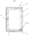
- Fig. 1 shows a window 10, the one with a not shown wall-mounted fixed frame 12th having. Connected to this frame 12 is a Sash frame 14, which is movable relative to the frame 12 is stored, and that about a vertical axis of rotation 16 and tiltable about a horizontal tilting axis 18.
- the window 10 is not shown on a wing frame side Espagnolette fitting and also not shown frame-side strike plates closed. The operation of the espagnolette is done via a Operating handle 20.
- the espagnolette fitting and the Striker plates are coordinated in this way, that the sash frame 14 relative to the frame 12 in a parallel position to ensure a Night ventilation can be brought.
- This corner warehouse takes a part the weight forces of the sash 14 and guaranteed a mobility about the axes of rotation 16, 18.
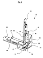
- Figs. 2 and 3 show a first embodiment of the corner bearing 22.
- the corner bearing 22 in Fig. 2 in a closed Position represented by the closed Window position in Fig. 1 corresponds.
- Fig. 3 is in contrast shown a rotationally open position, the a revolving sash, rotated about the axis of rotation 16, corresponds.
- the corner bearing 22 is composed from a first bearing part 28, with the frame 12th is connectable, and a second bearing part 30, with the sash 14 is connectable. Connected are first and second bearing part 28, 30 via connecting means, the from a first bearing member 28 associated connecting pin 32 and a second bearing part 30 associated Connection opening 34 exist.
- the first bearing part 28 consists of an angled Base plate 35, on the various auxiliary components, indirectly also the connecting pin 32, are attached and the can be connected to the frame 12.
- the second bearing part 30 consists of a support bracket 36, at the bottom the connection opening 34 is arranged, for example. This Carrying angle 36 can be inserted into a groove of the casement 14 and connectable with them.
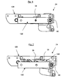
- Figs. 4 and 5 also show illustrations of the same Embodiment as shown in FIGS. 2 and 3 Corner bearing 22.
- corner bearing 22 with respect to the schematically indicated frame 12 and sash 14 is located.
- sash 14 a wing flap 38, in which a pocket-like area 40 is provided is received in the portions of the corner bearing 22 are.
- the pocket-like area 40 is closed Position of the window, as shown in Fig. 4th is shown, open in the direction of the frame 12 executed. Through this opening 42, the corner bearing 22 or parts of which protrude, wherein from the perspective of Interior space, as seen in Fig. 4 from the left, the corner bearing 22 is covered by the wing flap 38.
- the corner bearing 22 has second parking means 44, through the sash frame 14 relative to the frame 12 in a parked position can be brought, as shown in FIG. 5 can be seen.
- the parked position is in the Comparison of Figs. 4 and 5 recognizable, since the sash 14 relative to the frame 12 in Fig. 5 shifted to the left is and thereby results in a ventilation gap 46. In Fig. 4, such a ventilation gap is not present. It should be noted that this is about schematic representations in which the otherwise still needed seals of clarity half are not drawn.
- the second parking means 44 are in the second bearing part 30 arranged and each consist of a first and second slide guide 48, 50, in each of which a first and second bolt 52, 54 can be performed.
- the Bolts 52, 54 have a mushroom-like shape, wherein in Figs. 2, 4 and 5, only the heads recognizable are, compared to the bolt hulls a much larger Have diameter.
- the bolts 52, 54 are there within the slide guides 48, 50 forcibly guided.
- the corner bearing 22 has by the second parking means 44 an extra degree of freedom that it allows the sash frame 14 in the region of Corner bearing against the frame 12 in the required Move direction in a certain distance interval can.
- the distance is determined by the length of the slotted guides 48, 50 limited.
- the actual parking movement is from the espagnolette fitting and the Striking plates introduced, the corner bearing serves as a drive merely as a passive element and poses only the possibility of movement and of course the readiness ready to absorb the weight forces.
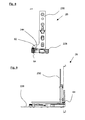
- FIGS. 6 and 7 show a corner bearing 24 of a second, alternative Embodiment, their installation situation opposite the sash and frame 14, 12 with the corner bearing 22nd matches. Also, the structural design of the corner bearing 24 is essentially the same as previously described Corner bearing 22 match, with the difference in the second Abstellstoff are executed differently.
- the corner warehouse 24 consists of a first bearing part 128 and a second Bearing part 130, the function of their bearing parts 28 and 30 of the corner bearing 22 correspond.
- a second Abstellstoff serves here a coupling element 56, the in Fig. 7 can be seen and in Fig. 6 by the second bearing part 130 is covered.
- the coupling element 56 connects the first bearing part 128 with the second bearing part 130, where it is one on the frame 12 and on the frame 12 associated first bearing part side 128 located first pivot axis 58 and about a second pivot axis 60 is pivotally mounted on the sash 14 and is located on the associated second bearing part 130.
- This mobility of the coupling element 56 is also a Abstellschulsdorfkeit created as this can be seen in the comparison of FIGS. 6 and 7.
- Fig. 6 is the corner bearing of the window in a closed position whereas in FIG. 7 it is paralleled is what offset by the down in Fig. 7 Position of the second bearing part 130 relative to the representation can be seen in Fig. 6.
- Figs. 8 and 9 show a third alternative embodiment of the corner bearing 26. It is true of its basic structure also with the two already described Corner bearings 22 and 24 match, again the second Abstellstoff constructively designed differently.
- the Corner bearing 26 consists of a first bearing part 228 and a second bearing part 230.
- the second parking means is thereby by a constructive change of the connection opening 62 formed with a slot-like Shape is provided. In this case, the longitudinal axis extends of the slot perpendicular to the window plane.
- this connection opening 62 along this slot movable Connecting pin 64 is also a degree of freedom to ensure a Abstellschul in the given form.
- corner bearings 22, 24, 26 are therefore suitable, a concealed corner bearing a additional degree of freedom to achieve a parallel job between casement 14 and frame 12th to give.
Landscapes
- Engineering & Computer Science (AREA)
- Mechanical Engineering (AREA)
- Wing Frames And Configurations (AREA)
- Hinges (AREA)
Abstract
Description
- Fig. 1
- Eine Draufsicht auf ein Fenster;
- Fig. 2
- eine räumliche Ansicht eines Ecklagers in geschlossenem Zustand;
- Fig. 3
- eine räumliche Ansicht eines Ecklagers in drehgeöffnetem Zustand;
- Fig. 4
- eine Seitenansicht eines Ecklagers mit einem Teilbereich des Fensters;
- Fig. 5
- ein Ecklager nach Fig. 4 in einem ausgelenkten Zustand;
- Fig. 6
- eine Draufsicht auf eine weitere Ausführungsform des Ecklagers;
- Fig. 7
- ein Ecklager nach Fig. 6 in einem ausgelenkten Zustand;
- Fig. 8
- eine Seitenansicht einer weiteren Ausführungsform des Ecklagers;
- Fig. 9
- eine Draufsicht auf ein Ecklager nach Fig. 8.
Claims (10)
- Fenster oder Tür, mit einem Blendrahmen (12) und einem gegenüber diesem um eine vertikale Drehachse (16) drehbaren und um eine horizontale Kippachse (18) kippbaren Flügelrahmen (14), sowie mit einem im Schnittpunkt der Drehachse (16) und der Kippachse (18) gelegenen Ecklager (22, 24, 26), wobei der Flügelrahmen (14) im Bereich eines Flügelüberschlags (38) einen taschenartigen Bereich (40) zur wenigstens teilweisen Aufnahme des Ecklagers (22, 24, 26) aufweist, und wobei der taschenartige Bereich (40) in geschlossener Stellung des Flügelrahmens (14) gegenüber dem Blendrahmen (12) in Richtung des Blendrahmens (12) eine Öffnung (42) aufweist, durch die das Ecklager (22, 24, 26) hindurchragen kann, wodurch das Ecklager (22, 24, 26) im geschlossenen Zustand des Fensters oder der Tür von dem Flügelüberschlag (38) abgedeckt ist, und wobei das Ecklager (22, 24, 26) ein blendrahmenseitiges erstes Lagerteil (28, 128, 228) und ein flügelrahmenseitiges zweites Lagerteil (30, 130, 230) aufweist, die mit Verbindungsmitteln aus einem Verbindungszapfen (32) und einer Verbindungsöffnung (34) verbindbar sind, und wobei das Ecklager (22, 24, 26) erste Abstellmittel (39) zur Erleichterung der Montage des Flügelrahmens (14) am Blendrahmen (12) aufweist, die einen Freiheitsgrad senkrecht zur durch die Drehachse (16) und die Kippachse (18) gebildeten Ebene besitzen, dadurch gekennzeichnet, dass das Ecklager (22, 24, 26) zweite Abstellmittel (44, 144, 244) aufweist, die eine Abstellung des Flügelrahmens (14) gegenüber dem Blendrahmen (12) im Bereich des Ecklagers (22, 24, 26) während der regelmäßigen Benutzung des Fensters erlauben, wobei die Abstellrichtung im wesentlichen senkrecht zur durch die Drehachse (16) und die Kippachse (18) gebildeten Ebene erfolgt.
- Fenster oder Tür nach Anspruch 1, dadurch gekennzeichnet, dass der Flügelrahmen (14) gegenüber dem Blendrahmen (12) auf der gesamten Kontaktfläche zwischen Flügelrahmen (14) und Blendrahmen (12) im wesentlichen parallel abstellbar ist.
- Fenster oder Tür nach einem der Ansprüche 1 oder 2, dadurch gekennzeichnet, dass die zweiten Abstellmittel (44) im zweiten Lagerteil (30) Kulissenführungen (48, 50) aufweisen, wobei die Kulissenführungen (48, 50) durch wenigstens zwei Bolzen (52, 54) auf der dem Flügelrahmen (14) zugewandten Seite und wenigstens zwei diesen Bolzen (52, 54) zugeordneten parallelen, geradlinigen Aussparungen (48, 50) auf der dem Flügelrahmen (14) abgewandten Seite gebildet sind, wobei die Bolzen (52, 54) in den Aussparungen (48, 50) zwangsgeführt sind.
- Fenster oder Tür nach Anspruch 3, dadurch gekennzeichnet, dass die Bolzen (52, 54) eine pilzkopfartige Form aufweisen.
- Fenster oder Tür nach einem der Ansprüche 1 oder 2, dadurch gekennzeichnet, dass die zweiten Abstellmittel (144) ein Koppelelement (56) zur Verbindung des ersten Lagerteils (128) und des zweiten Lagerteils 230) aufweisen, wobei das Koppelelement (56) um eine am Blendrahmen (12) gelegene erste Schwenkachse (58) sowie um eine am Flügelrahmen (14) gelegene zweite Schwenkachse (60) schwenkbar ist.
- Fenster oder Tür nach Anspruch 5, dadurch gekennzeichnet, dass das Koppelelement (56) auf einer Abstützfläche des blendrahmenseitigen ersten Lagerteils (128) abstützbar ist.
- Fenster oder Tür nach Anspruch 5 oder 6, dadurch gekennzeichnet, dass das Koppelelement (56) durch zwei übereinander liegende Koppelplatten gebildet ist.
- Fenster oder Tür nach Anspruch 5 oder 6, dadurch gekennzeichnet, dass das Koppelelement (56) einstückig, vorzugsweise als ein Sinterwerkstück, ausgeführt ist.
- Fenster oder Tür nach einem der Ansprüche 1 oder 2, dadurch gekennzeichnet, dass die zweiten Abstellmittel (244) durch die Verbindungsmittel gebildet sind, wobei die Verbindungsöffnung (62) eine senkrecht zur durch die Drehachse (16) und die Kippachse (18) gebildeten Ebene orientierte Langlochführung (62) aufweist.
- Fenster oder Tür nach einem der vorhergehenden Ansprüche, dadurch gekennzeichnet, dass der Flügelrahmen (14) gegenüber dem Blendrahmen (12) durch eine umlaufende, durchgängige Dichtung, die auch das Ecklager (22, 24, 26) mit einschließt, abgedichtet ist.
Applications Claiming Priority (2)
| Application Number | Priority Date | Filing Date | Title |
|---|---|---|---|
| DE102004009167 | 2004-02-25 | ||
| DE200410009167 DE102004009167A1 (de) | 2004-02-25 | 2004-02-25 | Fenster oder Tür |
Publications (2)
| Publication Number | Publication Date |
|---|---|
| EP1568839A2 true EP1568839A2 (de) | 2005-08-31 |
| EP1568839A3 EP1568839A3 (de) | 2013-04-10 |
Family
ID=34745272
Family Applications (1)
| Application Number | Title | Priority Date | Filing Date |
|---|---|---|---|
| EP05100377.0A Withdrawn EP1568839A3 (de) | 2004-02-25 | 2005-01-21 | Fenster oder Tür |
Country Status (2)
| Country | Link |
|---|---|
| EP (1) | EP1568839A3 (de) |
| DE (1) | DE102004009167A1 (de) |
Cited By (2)
| Publication number | Priority date | Publication date | Assignee | Title |
|---|---|---|---|---|
| EP1936086A1 (de) | 2006-12-23 | 2008-06-25 | ROTO FRANK Aktiengesellschaft | Ecklagerbeschlag für Fenster, Türen oder dgl. |
| DE202009006565U1 (de) | 2009-05-07 | 2010-09-23 | Siegenia-Aubi Kg | Beschlag |
Family Cites Families (8)
| Publication number | Priority date | Publication date | Assignee | Title |
|---|---|---|---|---|
| DE1933557A1 (de) * | 1969-07-02 | 1971-01-14 | Ver Fuer Tech Holzfragen E V | Fensterbeschlag |
| DE3043925C2 (de) * | 1980-11-03 | 1994-09-29 | Winkhaus Fa August | Vorrichtung an einem Fenster zur Einstellung des Flügelrahmens in eine Spaltöffnungsstellung |
| EP0419687B1 (de) * | 1989-09-20 | 1993-08-04 | Mila Beslag A/S | Verdeckt im Falz angeordnete Ausstellvorrichtung für Kipp-Schwenk-Flügel von Fenstern oder Türen |
| PL201187B1 (pl) * | 2000-03-22 | 2009-03-31 | Schueco Int Kg | Zestaw okuć do okna lub drzwi oraz okno lub drzwi |
| DE10128453A1 (de) * | 2001-06-12 | 2002-12-19 | Winkhaus Fa August | Fenster oder Fenstertür |
| DE10205009C2 (de) * | 2002-02-07 | 2003-12-04 | Roto Frank Ag | Verdeckt angeordneter Beschlag zwischen einem Flügel und einem festen Rahmen eines Fensters, einer Tür oder dergleichen |
| DE10326878A1 (de) * | 2003-06-14 | 2005-03-10 | Winkhaus Fa August | Fenster |
| ATE335114T1 (de) * | 2003-11-22 | 2006-08-15 | Roto Frank Ag | Fenster oder tür mit wenigstens einer verdeckt angeordneten beschlagschere zwischen einem festen rahmen und einem flügel |
-
2004
- 2004-02-25 DE DE200410009167 patent/DE102004009167A1/de not_active Withdrawn
-
2005
- 2005-01-21 EP EP05100377.0A patent/EP1568839A3/de not_active Withdrawn
Cited By (5)
| Publication number | Priority date | Publication date | Assignee | Title |
|---|---|---|---|---|
| EP1936086A1 (de) | 2006-12-23 | 2008-06-25 | ROTO FRANK Aktiengesellschaft | Ecklagerbeschlag für Fenster, Türen oder dgl. |
| DE202009006565U1 (de) | 2009-05-07 | 2010-09-23 | Siegenia-Aubi Kg | Beschlag |
| WO2010127718A1 (de) * | 2009-05-07 | 2010-11-11 | Siegenia-Aubi Kg | Beschlag |
| CN102421974A (zh) * | 2009-05-07 | 2012-04-18 | 丝吉利娅-奥彼两合责任公司 | 配件 |
| CN102421974B (zh) * | 2009-05-07 | 2014-04-30 | 丝吉利娅-奥彼两合责任公司 | 窗或门的翼扇与固定框架之间的配件 |
Also Published As
| Publication number | Publication date |
|---|---|
| EP1568839A3 (de) | 2013-04-10 |
| DE102004009167A1 (de) | 2005-09-15 |
Similar Documents
| Publication | Publication Date | Title |
|---|---|---|
| EP0515931B2 (de) | Drehkippbeschlag | |
| EP4180601B1 (de) | Türband mit länglichem führungsschlitten | |
| EP2130997B1 (de) | Tür mit einem Türband | |
| DE102008028598B4 (de) | Insektenschutztür | |
| EP0874102B1 (de) | Dachfenster, insbesondere Schwingflügel-Dachfenster | |
| EP1568839A2 (de) | Fenster oder Tür | |
| CH690451A5 (de) | Scharnier. | |
| DE4221083C2 (de) | Karusselltür | |
| DE10301046B4 (de) | Drehbeschlag für die verdeckte Anordnung an Türen oder Fenstern | |
| DE3249809C2 (de) | Beschlag zum schwenkbaren Befestigen einer Klappe an einem Schrank | |
| EP1245177B1 (de) | Drehlagerung einer Tür | |
| EP1422372A1 (de) | Fenster oder Tür | |
| EP3278693B1 (de) | Beschlag für eine schiebetüre | |
| DE10047978A1 (de) | Scharnier zum Anschlagen einer Möbeltür | |
| WO1990001099A1 (de) | Falttür mit mehreren flügelpaaren | |
| DE102009006847B4 (de) | Verkaufswagen | |
| DE2443036A1 (de) | Ausstellvorrichtung | |
| EP2287427B1 (de) | Einachsscharnier | |
| DE1708443A1 (de) | Beschlag fuer Kipp-Schwenkfluegel von Fenstern | |
| EP1019604B1 (de) | Verschlussvorrichtung mit horizontaler handhabe | |
| DE19825071A1 (de) | Parallelausstellfenster mit Drehfunktion | |
| DE2033018C3 (de) | Ausstellvorrichtung für Schwenk-Kipp-Flügel von Fenstern oder Türen | |
| DE1962906C3 (de) | Beschlag fur Dreh-Kipp- oder Dreh-Klappfenster | |
| DE10141115B4 (de) | Scharnier | |
| DE19961264A1 (de) | Haltebeschlag zum Halten eines Spiegels |
Legal Events
| Date | Code | Title | Description |
|---|---|---|---|
| PUAI | Public reference made under article 153(3) epc to a published international application that has entered the european phase |
Free format text: ORIGINAL CODE: 0009012 |
|
| AK | Designated contracting states |
Kind code of ref document: A2 Designated state(s): AT BE BG CH CY CZ DE DK EE ES FI FR GB GR HU IE IS IT LI LT LU MC NL PL PT RO SE SI SK TR |
|
| AX | Request for extension of the european patent |
Extension state: AL BA HR LV MK YU |
|
| PUAL | Search report despatched |
Free format text: ORIGINAL CODE: 0009013 |
|
| AK | Designated contracting states |
Kind code of ref document: A3 Designated state(s): AT BE BG CH CY CZ DE DK EE ES FI FR GB GR HU IE IS IT LI LT LU MC NL PL PT RO SE SI SK TR |
|
| AX | Request for extension of the european patent |
Extension state: AL BA HR LV MK YU |
|
| RIC1 | Information provided on ipc code assigned before grant |
Ipc: E05D 15/32 20060101ALI20130305BHEP Ipc: E05D 3/02 20060101ALI20130305BHEP Ipc: E05D 15/52 20060101AFI20130305BHEP |
|
| AKX | Designation fees paid |
Designated state(s): AT BE BG CH CY CZ DE DK EE ES FI FR GB GR HU IE IS IT LI LT LU MC NL PL PT RO SE SI SK TR |
|
| STAA | Information on the status of an ep patent application or granted ep patent |
Free format text: STATUS: THE APPLICATION IS DEEMED TO BE WITHDRAWN |
|
| 18D | Application deemed to be withdrawn |
Effective date: 20131011 |