EP1568839A2 - Window or door - Google Patents
Window or door Download PDFInfo
- Publication number
- EP1568839A2 EP1568839A2 EP05100377A EP05100377A EP1568839A2 EP 1568839 A2 EP1568839 A2 EP 1568839A2 EP 05100377 A EP05100377 A EP 05100377A EP 05100377 A EP05100377 A EP 05100377A EP 1568839 A2 EP1568839 A2 EP 1568839A2
- Authority
- EP
- European Patent Office
- Prior art keywords
- frame
- window
- corner
- axis
- bearing
- Prior art date
- Legal status (The legal status is an assumption and is not a legal conclusion. Google has not performed a legal analysis and makes no representation as to the accuracy of the status listed.)
- Withdrawn
Links
Images


Classifications
-
- E—FIXED CONSTRUCTIONS
- E05—LOCKS; KEYS; WINDOW OR DOOR FITTINGS; SAFES
- E05D—HINGES OR SUSPENSION DEVICES FOR DOORS, WINDOWS OR WINGS
- E05D15/00—Suspension arrangements for wings
- E05D15/48—Suspension arrangements for wings allowing alternative movements
- E05D15/52—Suspension arrangements for wings allowing alternative movements for opening about a vertical as well as a horizontal axis
- E05D15/5211—Concealed suspension fittings
-
- E—FIXED CONSTRUCTIONS
- E05—LOCKS; KEYS; WINDOW OR DOOR FITTINGS; SAFES
- E05D—HINGES OR SUSPENSION DEVICES FOR DOORS, WINDOWS OR WINGS
- E05D15/00—Suspension arrangements for wings
- E05D15/48—Suspension arrangements for wings allowing alternative movements
- E05D15/52—Suspension arrangements for wings allowing alternative movements for opening about a vertical as well as a horizontal axis
- E05D15/5214—Corner supports
-
- E—FIXED CONSTRUCTIONS
- E05—LOCKS; KEYS; WINDOW OR DOOR FITTINGS; SAFES
- E05D—HINGES OR SUSPENSION DEVICES FOR DOORS, WINDOWS OR WINGS
- E05D3/00—Hinges with pins
- E05D3/02—Hinges with pins with one pin
- E05D3/022—Hinges with pins with one pin allowing an additional lateral movement, e.g. for sealing
-
- E—FIXED CONSTRUCTIONS
- E05—LOCKS; KEYS; WINDOW OR DOOR FITTINGS; SAFES
- E05Y—INDEXING SCHEME RELATING TO HINGES OR OTHER SUSPENSION DEVICES FOR DOORS, WINDOWS OR WINGS AND DEVICES FOR MOVING WINGS INTO OPEN OR CLOSED POSITION, CHECKS FOR WINGS AND WING FITTINGS NOT OTHERWISE PROVIDED FOR, CONCERNED WITH THE FUNCTIONING OF THE WING
- E05Y2900/00—Application of doors, windows, wings or fittings thereof
- E05Y2900/10—Application of doors, windows, wings or fittings thereof for buildings or parts thereof
- E05Y2900/13—Application of doors, windows, wings or fittings thereof for buildings or parts thereof characterised by the type of wing
- E05Y2900/148—Windows
Definitions
- the invention relates to a window or a door, with a Frame and one opposite this to a vertical Turning axis rotatable and about a horizontal tilt axis tiltable sash, as well as one in the intersection the pivot axis and the tilt axis located corner bearing, wherein the sash in the area of a wing flap a pocket-like area for at least partial Receiving the Ecklagers, and wherein the pocket-like Area in closed position of the sash opposite the frame in the direction of the frame has an opening through which the corner bearing protrude can, causing the corner bearing in the closed state the window or door covered by the wing flap is, and wherein the corner bearing a bezel side first bearing part and a wing frame side second bearing part having, with connecting means of a Connecting pin and a connection opening connectable are and where the corner bearing first Abstellstoff to facilitate the installation of the sash frame on the frame having a degree of freedom perpendicular to through the Have axis of rotation and the tilt axis formed plane
- Such a window or door is from the DE 101 28 453 A1 known. It is a window or a door in which the fitting and its components, especially the corner bearing, from the interior of the room are not visible. This is achieved by a Part of the corner bearing in a pocket of the sash and thus arranged concealed by the sash is.
- the corner bearing is designed as a pure turn-tilt bearing. Only in the case of mounting the sash on the frame, the corner bearing first Abstellstoff on, which is a temporary stopping movement of the sash opposite the glare frame perpendicular to the window plane allow in the direction of the room interior Swing out an auxiliary lever.
- a window or a door known by the / the sash parked parallel to the frame can be.
- the night ventilation position is provided with guide plates provided with sliding guides, a scissors provided with a slotted guide and a provided with an additional degree of freedom Ecklager reached.
- the slide guides have a plane offset on, through which generates the Abstell Gay becomes.
- the disadvantage of this type of corner bearing is that Parts of it from inside the room is visible and thus one uniform visual impression at the transition between disturb the sash and the frame.
- From DE 199 29 818 A1 is a fitting for a window or a door with a night ventilation position known. It is also opposite by moving the sash the frame around the entire wing circumference Night ventilation position possible. In the area of the corner warehouse is a parking movement by a tiltable Lever arm possible. A disadvantage of such a corner bearing is also that parts of it visible from inside the room is.
- the invention is based on the object, a window or to further develop a door of the type mentioned at the outset, that the function of the concealed corner bearing and ensuring a parking movement in the area of Ecklagers be agreed with each other.
- the corner bearing second parking means having a shutdown of the sash against the frame in the area corner store during regular use of the window allow, with the Abstellraum substantially perpendicular to the axis of rotation and the tilt axis formed Level takes place.
- the perpendicular to the Wing frame plane aligned storage direction is for the operation of the window an additional degree of freedom given against a normal turn-tilt window.
- abuts In order to It allows the sash frame in a particular To switch off the distance interval with respect to the frame, until it stops at an end stop, which is part of the second stop means is, abuts.
- the second parking means in the second bearing part Sliding guides have, with the slotted guides by at least two bolts on the sash facing side and at least two of these Bolt associated parallel, rectilinear recesses are formed on the side facing away from the sash, the bolts being constrained in the recesses, and wherein the bolts have a mushroom-like shape.
- the second parking means can be particularly good the large Weighing forces acting on the second shutdown of the Sash frames must be transferred to the frame, be recorded. This is still supported by the arrangement of two parallel sliding guides, the one hand, for a clear forced guidance in the required Abstellraum and on the other hand for ensure a better distribution of the loads.
- the second parking means a coupling element for connecting the first bearing part and the second bearing part, wherein the coupling element around a first pivot axis located on the frame as well as a second pivot axis located on the sash frame is pivotable, and wherein the coupling element on a Support surface of the frame side first bearing part is supportable.
- the coupling element by two superimposed lying coupling plates is formed or alternatively in one piece, preferably as a sintered workpiece is.
- the two superposed coupling plates have the advantage that they are structurally simple can be produced, wherein the one-piece solution of a Sintered metal material has the advantage of greater stability and deformation under load.
- the sash frame faces the frame through a circumferential, continuous seal that too the corner bearing includes, is sealed.
- the seal in the area of the corner bearing is not interrupted is, is a particularly reliable seal between the interior and the outside atmosphere possible.
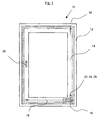
- Fig. 1 shows a window 10, the one with a not shown wall-mounted fixed frame 12th having. Connected to this frame 12 is a Sash frame 14, which is movable relative to the frame 12 is stored, and that about a vertical axis of rotation 16 and tiltable about a horizontal tilting axis 18.
- the window 10 is not shown on a wing frame side Espagnolette fitting and also not shown frame-side strike plates closed. The operation of the espagnolette is done via a Operating handle 20.
- the espagnolette fitting and the Striker plates are coordinated in this way, that the sash frame 14 relative to the frame 12 in a parallel position to ensure a Night ventilation can be brought.
- This corner warehouse takes a part the weight forces of the sash 14 and guaranteed a mobility about the axes of rotation 16, 18.
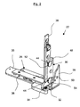
- Figs. 2 and 3 show a first embodiment of the corner bearing 22.
- the corner bearing 22 in Fig. 2 in a closed Position represented by the closed Window position in Fig. 1 corresponds.
- Fig. 3 is in contrast shown a rotationally open position, the a revolving sash, rotated about the axis of rotation 16, corresponds.
- the corner bearing 22 is composed from a first bearing part 28, with the frame 12th is connectable, and a second bearing part 30, with the sash 14 is connectable. Connected are first and second bearing part 28, 30 via connecting means, the from a first bearing member 28 associated connecting pin 32 and a second bearing part 30 associated Connection opening 34 exist.
- the first bearing part 28 consists of an angled Base plate 35, on the various auxiliary components, indirectly also the connecting pin 32, are attached and the can be connected to the frame 12.
- the second bearing part 30 consists of a support bracket 36, at the bottom the connection opening 34 is arranged, for example. This Carrying angle 36 can be inserted into a groove of the casement 14 and connectable with them.
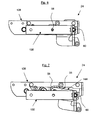
- Figs. 4 and 5 also show illustrations of the same Embodiment as shown in FIGS. 2 and 3 Corner bearing 22.
- corner bearing 22 with respect to the schematically indicated frame 12 and sash 14 is located.
- sash 14 a wing flap 38, in which a pocket-like area 40 is provided is received in the portions of the corner bearing 22 are.
- the pocket-like area 40 is closed Position of the window, as shown in Fig. 4th is shown, open in the direction of the frame 12 executed. Through this opening 42, the corner bearing 22 or parts of which protrude, wherein from the perspective of Interior space, as seen in Fig. 4 from the left, the corner bearing 22 is covered by the wing flap 38.
- the corner bearing 22 has second parking means 44, through the sash frame 14 relative to the frame 12 in a parked position can be brought, as shown in FIG. 5 can be seen.
- the parked position is in the Comparison of Figs. 4 and 5 recognizable, since the sash 14 relative to the frame 12 in Fig. 5 shifted to the left is and thereby results in a ventilation gap 46. In Fig. 4, such a ventilation gap is not present. It should be noted that this is about schematic representations in which the otherwise still needed seals of clarity half are not drawn.
- the second parking means 44 are in the second bearing part 30 arranged and each consist of a first and second slide guide 48, 50, in each of which a first and second bolt 52, 54 can be performed.
- the Bolts 52, 54 have a mushroom-like shape, wherein in Figs. 2, 4 and 5, only the heads recognizable are, compared to the bolt hulls a much larger Have diameter.
- the bolts 52, 54 are there within the slide guides 48, 50 forcibly guided.
- the corner bearing 22 has by the second parking means 44 an extra degree of freedom that it allows the sash frame 14 in the region of Corner bearing against the frame 12 in the required Move direction in a certain distance interval can.
- the distance is determined by the length of the slotted guides 48, 50 limited.
- the actual parking movement is from the espagnolette fitting and the Striking plates introduced, the corner bearing serves as a drive merely as a passive element and poses only the possibility of movement and of course the readiness ready to absorb the weight forces.
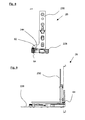
- FIGS. 6 and 7 show a corner bearing 24 of a second, alternative Embodiment, their installation situation opposite the sash and frame 14, 12 with the corner bearing 22nd matches. Also, the structural design of the corner bearing 24 is essentially the same as previously described Corner bearing 22 match, with the difference in the second Abstellstoff are executed differently.
- the corner warehouse 24 consists of a first bearing part 128 and a second Bearing part 130, the function of their bearing parts 28 and 30 of the corner bearing 22 correspond.
- a second Abstellstoff serves here a coupling element 56, the in Fig. 7 can be seen and in Fig. 6 by the second bearing part 130 is covered.
- the coupling element 56 connects the first bearing part 128 with the second bearing part 130, where it is one on the frame 12 and on the frame 12 associated first bearing part side 128 located first pivot axis 58 and about a second pivot axis 60 is pivotally mounted on the sash 14 and is located on the associated second bearing part 130.
- This mobility of the coupling element 56 is also a Abstellschulsdorfkeit created as this can be seen in the comparison of FIGS. 6 and 7.
- Fig. 6 is the corner bearing of the window in a closed position whereas in FIG. 7 it is paralleled is what offset by the down in Fig. 7 Position of the second bearing part 130 relative to the representation can be seen in Fig. 6.
- Figs. 8 and 9 show a third alternative embodiment of the corner bearing 26. It is true of its basic structure also with the two already described Corner bearings 22 and 24 match, again the second Abstellstoff constructively designed differently.
- the Corner bearing 26 consists of a first bearing part 228 and a second bearing part 230.
- the second parking means is thereby by a constructive change of the connection opening 62 formed with a slot-like Shape is provided. In this case, the longitudinal axis extends of the slot perpendicular to the window plane.
- this connection opening 62 along this slot movable Connecting pin 64 is also a degree of freedom to ensure a Abstellschul in the given form.
- corner bearings 22, 24, 26 are therefore suitable, a concealed corner bearing a additional degree of freedom to achieve a parallel job between casement 14 and frame 12th to give.
Abstract
Description
Die Erfindung betrifft ein Fenster oder eine Tür, mit einem Blendrahmen und einem gegenüber diesem um eine vertikale Drehachse drehbaren und um eine horizontale Kippachse kippbaren Flügelrahmen, sowie mit einem im Schnittpunkt der Drehachse und der Kippachse gelegenen Ecklager, wobei der Flügelrahmen im Bereich eines Flügelüberschlags einen taschenartigen Bereich zur wenigstens teilweisen Aufnahme des Ecklagers aufweist, und wobei der taschenartige Bereich in geschlossener Stellung des Flügelrahmens gegenüber dem Blendrahmen in Richtung des Blendrahmens eine Öffnung aufweist, durch die das Ecklager hindurchragen kann, wodurch das Ecklager im geschlossenen Zustand des Fensters oder der Tür von dem Flügelüberschlag abgedeckt ist, und wobei das Ecklager ein blendrahmenseitiges erstes Lagerteil und ein flügelrahmenseitiges zweites Lagerteil aufweist, die mit Verbindungsmitteln aus einem Verbindungszapfen und einer Verbindungsöffnung verbindbar sind und wobei das Ecklager erste Abstellmittel zur Erleichterung der Montage des Flügelrahmens am Blendrahmen aufweist, die einen Freiheitsgrad senkrecht zur durch die Drehachse und die Kippachse gebildeten Ebene besitzen.The invention relates to a window or a door, with a Frame and one opposite this to a vertical Turning axis rotatable and about a horizontal tilt axis tiltable sash, as well as one in the intersection the pivot axis and the tilt axis located corner bearing, wherein the sash in the area of a wing flap a pocket-like area for at least partial Receiving the Ecklagers, and wherein the pocket-like Area in closed position of the sash opposite the frame in the direction of the frame has an opening through which the corner bearing protrude can, causing the corner bearing in the closed state the window or door covered by the wing flap is, and wherein the corner bearing a bezel side first bearing part and a wing frame side second bearing part having, with connecting means of a Connecting pin and a connection opening connectable are and where the corner bearing first Abstellmittel to facilitate the installation of the sash frame on the frame having a degree of freedom perpendicular to through the Have axis of rotation and the tilt axis formed plane.
Ein solches Fenster oder eine solche Tür ist aus der DE 101 28 453 A1 bekannt. Es handelt sich dabei um ein Fenster oder eine Tür, bei dem der Beschlag und seine Komponenten, insbesondere das Ecklager, vom Rauminnern her nicht sichtbar sind. Dieses wird erreicht, indem ein Teilbereich des Ecklagers in einer Tasche des Flügelrahmens und damit durch den Flügelrahmen verdeckt angeordnet ist. Das Ecklager ist als reines Dreh-Kipp-Lager ausgeführt. Lediglich für den Fall der Montage des Flügelrahmens am Blendrahmen weist das Ecklager erste Abstellmittel auf, die eine vorübergehende Abstellbewegung des Flügelrahmens gegenüber dem Blendrahme senkrecht zur Fensterebene in Richtung des Rauminnern ermöglichen durch Ausschwenken eines Hilfshebels.Such a window or door is from the DE 101 28 453 A1 known. It is a window or a door in which the fitting and its components, especially the corner bearing, from the interior of the room are not visible. This is achieved by a Part of the corner bearing in a pocket of the sash and thus arranged concealed by the sash is. The corner bearing is designed as a pure turn-tilt bearing. Only in the case of mounting the sash on the frame, the corner bearing first Abstellmittel on, which is a temporary stopping movement of the sash opposite the glare frame perpendicular to the window plane allow in the direction of the room interior Swing out an auxiliary lever.
Aus der nicht vorveröffentlichten DE 102 54 537 A1 ist ein Fenster oder eine Tür bekannt, bei dem/der der Flügelrahmen gegenüber dem Blendrahmen parallel abgestellt werden kann. Dadurch wird eine Spaltlüftungsfunktion gewährleistet, die gegenüber einer Kippstellung eine erhöhte Einbruchsicherheit aufweist. Die Spaltlüftungsstellung wird über mit Kulissenführungen versehenen Schließbleche, eine mit einer Kulissenführung versehene Schere sowie ein mit einem zusätzlichen Freiheitsgrad versehenen Ecklager erreicht. Die Kulissenführungen weisen dabei einen Ebenenversatz auf, durch den die Abstellbewegung erzeugt wird. Nachteilig an dieser Art des Ecklagers ist, dass Teile davon vom Rauminnern her sichtbar ist und damit einen einheitlichen optischen Eindruck am Übergang zwischen dem Flügelrahmen und dem Blendrahmen stören.From the unpublished DE 102 54 537 A1 a window or a door known by the / the sash parked parallel to the frame can be. This ensures a night ventilation function, which increased compared to a tilted position Burglar resistance. The night ventilation position is provided with guide plates provided with sliding guides, a scissors provided with a slotted guide and a provided with an additional degree of freedom Ecklager reached. The slide guides have a plane offset on, through which generates the Abstellbewegung becomes. The disadvantage of this type of corner bearing is that Parts of it from inside the room is visible and thus one uniform visual impression at the transition between disturb the sash and the frame.
Aus der DE 199 29 818 A1 ist ein Beschlag für ein Fenster oder eine Tür mit einer Spaltlüftungsstellung bekannt. Dabei ist ebenfalls durch Abrücken des Flügelrahmens gegenüber dem Blendrahmen um den gesamten Flügelumfang eine Spaltlüftungsstellung ermöglicht. Im Bereich des Ecklagers ist eine Abstellbewegung durch einen verkippbaren Hebelarm möglich. Nachteilig an einem solchen Ecklager ist ebenfalls, dass Teile davon vom Rauminnern her sichtbar ist. From DE 199 29 818 A1 is a fitting for a window or a door with a night ventilation position known. It is also opposite by moving the sash the frame around the entire wing circumference Night ventilation position possible. In the area of the corner warehouse is a parking movement by a tiltable Lever arm possible. A disadvantage of such a corner bearing is also that parts of it visible from inside the room is.
Aus der DE 198 25 071 C2 ist ein Parallelausstellfenster mit Drehfunktion bekannt. Dabei ist ebenfalls eine parallele Abstellung des Flügelrahmens gegenüber dem Blendrahmen möglich, wobei im Bereich des Ecklagers eine geradlinige Kulissenführung zum Ausgleich des Abstellabstandes eingesetzt wird. Nachteilig an einem solchen Ecklager ist ebenfalls, dass Teile davon vom Rauminnern her sichtbar ist.From DE 198 25 071 C2 is a Parallelausstellfenster known with rotary function. Here is also a parallel Shutdown of the casement with respect to the frame possible, wherein in the area of the corner bearing a rectilinear Slotted guide to compensate for the parking distance is used. The disadvantage of such a corner bearing also that parts of it visible from inside the room is.
Aus der DE 30 43 926 A1 ist ein Fenster mit einer Spaltkipp- oder Spaltdrehfunktion bekannt. Dabei liegt der Schwerpunkt ebenfalls in der Umsetzung einer Spaltlüftungsfunktion, wobei die Abstellung ebenfalls durch ebenenversetzte Kulissenführungen in den Schließblechen erfolgt. Im Bereich des Ecklagers wird auf eine Abstellung verzichtet und eine gewisse Verwindung des Flügelrahmens in Kauf genommen. Nachteilig ist ebenfalls, dass Teilbereiche des Ecklagers vom Rauminnern her sichtbar sind.From DE 30 43 926 A1 a window with a Spaltschwipp- or gap rotation function known. It lies the Emphasis also on the implementation of a night ventilation function, the shutdown also by plane offset Slotted guides are in the strike plates. In the area of the corner warehouse is on a parking waived and a certain twist of the sash accepted. Another disadvantage is that subregions of the corner bearing are visible from inside the room.
Aus der DE 30 43 925 C2 ist eine Vorrichtung an einem Fenster zur Einstellung einer Spaltlüftungsstellung bekannt. Die Spaltlüftungsstellung wird dabei ebenfalls durch ebenenversetzte Kulissenführungen in den Schließblechen ermöglicht. Nachteilig ist dabei ebenfalls die Sichtbarkeit vom Rauminnern her.From DE 30 43 925 C2 is a device on a Window for setting a night ventilation position known. The night ventilation position is also here by plane offset slide guides in the striking plates allows. The disadvantage is also the Visibility from inside the room.
Der Erfindung liegt die Aufgabe zugrunde, ein Fenster oder eine Tür der eingangs genannten Art derart weiterzubilden, dass die Funktion des verdeckten Ecklagers und die Gewährleistung einer Abstellbewegung im Bereich des Ecklagers miteinander vereinbart werden. The invention is based on the object, a window or to further develop a door of the type mentioned at the outset, that the function of the concealed corner bearing and ensuring a parking movement in the area of Ecklagers be agreed with each other.
Zur Lösung dieser Aufgabe ist vorgesehen, dass das Ecklager zweite Abstellmittel aufweist, die eine Abstellung des Flügelrahmens gegenüber dem Blendrahmen im Bereich des Ecklagers während der regelmäßigen Benutzung des Fensters erlauben, wobei die Abstellrichtung im wesentlichen senkrecht zur durch die Drehachse und die Kippachse gebildeten Ebene erfolgt. Durch die senkrecht gegenüber der Flügelrahmenebene ausgerichtete Abstellrichtung ist für die Bedienung des Fensters ein zusätzlicher Freiheitsgrad gegenüber einem normalen Dreh-Kipp-Fenster gegeben. Damit ist es ermöglicht, den Flügelrahmen in einem bestimmten Distanz-Intervall gegenüber dem Blendrahmen abzustellen, bis er an einen Endanschlag, der Teil der zweiten Abstellmittel ist, anstößt. Dadurch ist ein an sich bekannter verdeckt liegender Beschlag mit einem verdeckt liegenden Ecklager mit einer weiteren Funktion versehen, nämlich der Gewährleistung einer Abstellbewegung im Bereich des Ecklagers. Diese Abstellbewegung wird durch die zweiten Abstellmittel bewirkt.To solve this problem, it is provided that the corner bearing second parking means having a shutdown of the sash against the frame in the area corner store during regular use of the window allow, with the Abstellrichtung substantially perpendicular to the axis of rotation and the tilt axis formed Level takes place. By the perpendicular to the Wing frame plane aligned storage direction is for the operation of the window an additional degree of freedom given against a normal turn-tilt window. In order to It allows the sash frame in a particular To switch off the distance interval with respect to the frame, until it stops at an end stop, which is part of the second stop means is, abuts. This is a known per se concealed fitting with a concealed Corner bearing provided with another function, namely the guarantee of a Abstellbewegung in the area the corner warehouse. This Abstellbewegung is through the second shutdown causes.
In weiterer Ausgestaltung der Erfindung ist gemäß Anspruch 2 vorgesehen, dass der Flügelrahmen gegenüber dem Blendrahmen auf der gesamten Kontaktfläche zwischen Flügelrahmen und Blendrahmen im wesentlichen parallel abstellbar ist. Es ist somit auch möglich, dieses der Erfindung zugrunde liegende Ecklager mit anderen an sich bekannten Beschlagskomponenten, beispielsweise Schließblechen, zu kombinieren, die ebenfalls eine Abstellbewegung ermöglichen. Damit ist es möglich, einen vollständig verdeckt liegenden Beschlag mit integrierter Abstellfunktion herzustellen.In a further embodiment of the invention is according to claim 2 provided that the sash against the Frame on the entire contact surface between casement frame and frame substantially parallel off is. It is thus also possible, this of the invention underlying corner camp with others in itself known fitting components, such as strike plates, to combine, which is also a parking movement enable. This makes it possible to get a complete one concealed fitting with integrated storage function manufacture.
In Weiterbildung der Erfindung ist gemäß Anspruch 3 und 4 vorgesehen, dass die zweiten Abstellmittel im zweiten Lagerteil Kulissenführungen aufweisen, wobei die Kulissenführungen durch wenigstens zwei Bolzen auf der dem Flügelrahmen zugewandten Seite und wenigstens zwei diesen Bolzen zugeordneten parallelen, geradlinigen Aussparungen auf der dem Flügelrahmen abgewandten Seite gebildet sind, wobei die Bolzen in den Aussparungen zwangsgeführt sind, und wobei die Bolzen eine pilzkopfartige Form aufweisen. Durch diese erste von drei genannten Ausführungsformen der zweiten Abstellmittel können besonders gut die großen Gewichtskräfte, die über die zweiten Abstellmittel vom Flügelrahmen auf den Blendrahmen übertragen werden müssen, aufgenommen werden. Dieses wird noch unterstützt durch die Anordnung von zwei parallelen Kulissenführungen, die einerseits für eine eindeutige Zwangsführung in die erforderliche Abstellrichtung und andererseits für eine bessere Verteilung der Lasten sorgen.In development of the invention according to claim 3 and 4 provided that the second parking means in the second bearing part Sliding guides have, with the slotted guides by at least two bolts on the sash facing side and at least two of these Bolt associated parallel, rectilinear recesses are formed on the side facing away from the sash, the bolts being constrained in the recesses, and wherein the bolts have a mushroom-like shape. Through this first of three mentioned embodiments the second parking means can be particularly good the large Weighing forces acting on the second shutdown of the Sash frames must be transferred to the frame, be recorded. This is still supported by the arrangement of two parallel sliding guides, the one hand, for a clear forced guidance in the required Abstellrichtung and on the other hand for ensure a better distribution of the loads.
In weiterer Ausgestaltung der Erfindung ist gemäß Anspruch 5 und 6 vorgesehen, dass die zweiten Abstellmittel ein Koppelelement zur Verbindung des ersten Lagerteils und des zweiten Lagerteils aufweisen, wobei das Koppelelement um eine am Blendrahmen gelegene erste Schwenkachse sowie um eine am Flügelrahmen gelegene zweite Schwenkachse schwenkbar ist, und wobei das Koppelelement auf einer Abstützfläche des blendrahmenseitigen ersten Lagerteils abstützbar ist. Durch diese zweite von drei genannten Ausführungsformen sind gegenüber dem bekannten Ecklager lediglich auf der dem Blendrahmen zugewandten ersten Lagerteil konstruktive Änderungen durchzuführen. Die hohen einwirkenden Gewichtskräfte können dabei über eine Abstützfläche abgefangen werden, so dass die Lagerungen im Bereich der ersten und zweiten Schwenkachsen entlastet werden. In a further embodiment of the invention is according to claim 5 and 6 provided that the second parking means a coupling element for connecting the first bearing part and the second bearing part, wherein the coupling element around a first pivot axis located on the frame as well as a second pivot axis located on the sash frame is pivotable, and wherein the coupling element on a Support surface of the frame side first bearing part is supportable. By this second of three mentioned Embodiments are compared to the known corner bearing only on the frame facing the first bearing part to carry out constructive changes. The high acting weight forces can have a support surface be intercepted, so that the bearings in the Relieved area of the first and second pivot axes become.
In Weiterbildung der Erfindung ist gemäß Anspruch 7 oder 8 vorgesehen, dass das Koppelelement durch zwei übereinander liegende Koppelplatten gebildet ist oder alternativ einstückig, vorzugsweise als ein Sinterwerkstück, ausgeführt ist. Die zwei übereinander liegenden Koppelplatten haben dabei den Vorteil, dass sie konstruktiv einfach herstellbar sind, wobei die einstückige Lösung aus einem Sintermetallwerkstoff den Vorteil einer größeren Stabilität und Verformung bei Belastung hat.In a further development of the invention is according to claim 7 or 8 provided that the coupling element by two superimposed lying coupling plates is formed or alternatively in one piece, preferably as a sintered workpiece is. The two superposed coupling plates have the advantage that they are structurally simple can be produced, wherein the one-piece solution of a Sintered metal material has the advantage of greater stability and deformation under load.
In weiterer Ausgestaltung der Erfindung ist gemäß Anspruch 9 vorgesehen, dass die zweiten Abstellmittel durch die Verbindungsmittel gebildet sind, wobei die Verbindungsöffnung eine senkrecht zur durch die Drehachse und die Kippachse gebildeten Ebene orientierte Langlochführung aufweist. Durch diese dritte von drei genannten Ausführungsformen ist eine besonders einfache und kostengünstige Lösung erzielt, da lediglich die geometrische Form der Verbindungsöffnung angepasst zu werden braucht.In a further embodiment of the invention is according to claim 9 provided that the second parking means the connecting means are formed, wherein the connecting opening a perpendicular to the axis of rotation and the tilt axis formed plane oriented slot guide having. Through this third of three mentioned embodiments is a particularly simple and inexpensive Solution achieved because only the geometric shape the connection opening needs to be adjusted.
In Weiterbildung der Erfindung ist gemäß Anspruch 10 vorgesehen,
dass der Flügelrahmen gegenüber dem Blendrahmen
durch eine umlaufende, durchgängige Dichtung, die auch
das Ecklager mit einschließt, abgedichtet ist. Dadurch,
dass die Dichtung im Bereich des Ecklagers nicht unterbrochen
ist, ist eine besonders zuverlässige Abdichtung
zwischen dem Innenraum und der Außenatmosphäre möglich.In a further development of the invention is provided according to
Anhand der folgenden Ausführungsbeispiele wird die Erfindung näher erläutert. Dabei zeigt:
- Fig. 1
- Eine Draufsicht auf ein Fenster;
- Fig. 2
- eine räumliche Ansicht eines Ecklagers in geschlossenem Zustand;
- Fig. 3
- eine räumliche Ansicht eines Ecklagers in drehgeöffnetem Zustand;
- Fig. 4
- eine Seitenansicht eines Ecklagers mit einem Teilbereich des Fensters;
- Fig. 5
- ein Ecklager nach Fig. 4 in einem ausgelenkten Zustand;
- Fig. 6
- eine Draufsicht auf eine weitere Ausführungsform des Ecklagers;
- Fig. 7
- ein Ecklager nach Fig. 6 in einem ausgelenkten Zustand;
- Fig. 8
- eine Seitenansicht einer weiteren Ausführungsform des Ecklagers;
- Fig. 9
- eine Draufsicht auf ein Ecklager nach Fig. 8.
- Fig. 1
- A top view of a window;
- Fig. 2
- a spatial view of a corner bearing in the closed state;
- Fig. 3
- a spatial view of a corner bearing in the rotationally open state;
- Fig. 4
- a side view of a corner bearing with a portion of the window;
- Fig. 5
- a corner bearing of Figure 4 in a deflected state.
- Fig. 6
- a plan view of another embodiment of the corner bearing;
- Fig. 7
- a corner bearing of Figure 6 in a deflected state.
- Fig. 8
- a side view of another embodiment of the corner bearing;
- Fig. 9
- a plan view of a corner bearing of FIG .. 8
Fig. 1 zeigt ein Fenster 10, das einen mit einer nicht
dargestellten Wand verbundenen ortsfesten Blendrahmen 12
aufweist. Mit diesem Blendrahmen 12 verbunden ist ein
Flügelrahmen 14, der gegenüber dem Blendrahmen 12 beweglich
gelagert ist, und zwar um eine vertikale Drehachse
16 drehbar und um eine horizontale Kippachse 18 kippbar.
Das Fenster 10 ist über einen nicht dargestellten flügelrahmenseitigen
Treibstangenbeschlag und ebenfalls nicht
dargestellte rahmenseitige Schließbleche verschließbar.
Die Bedienung des Treibstangenbeschlages erfolgt über einen
Bediengriff 20. Der Treibstangenbeschlag und die
Schließbleche sind dabei derart aufeinander abgestimmt,
dass der Flügelrahmen 14 gegenüber dem Blendrahmen 12 in
eine parallel abgerückte Stellung zur Gewährleistung einer
Spaltlüftung gebracht werden kann.Fig. 1 shows a
Im Schnittpunkt der Drehachsen 16, 18 ist ein Ecklager
22, 24, 26 angeordnet. Diese Ecklager nimmt einen Teil
der Gewichtskräfte des Flügelrahmens 14 auf und gewährleistet
eine Beweglichkeit um die Drehachsen 16, 18. At the intersection of the axes of
Fig. 2 und 3 zeigen eine erste Ausführungsform des Ecklagers
22. Dabei ist das Ecklager 22 in Fig. 2 in einer geschlossenen
Position dargestellt, die der geschlossenen
Fensterposition in Fig. 1 entspricht. In Fig. 3 ist demgegenüber
eine drehgeöffnete Position dargestellt, die
einem drehgeöffneten Flügelrahmen, gedreht um die Drehachse
16, entspricht. Das Ecklager 22 setzt sich zusammen
aus einem ersten Lagerteil 28, das mit dem Blendrahmen 12
verbindbar ist, sowie einem zweiten Lagerteil 30, das mit
dem Flügelrahmen 14 verbindbar ist. Verbunden sind das
erste und zweite Lagerteil 28, 30 über Verbindungsmittel,
die aus einem dem ersten Lagerteil 28 zugeordneten Verbindungszapfen
32 und einer dem zweiten Lagerteil 30 zugeordneten
Verbindungsöffnung 34 bestehen.Figs. 2 and 3 show a first embodiment of the
Das erste Lagerteil 28 besteht aus einer abgewinkelten
Grundplatte 35, an der diverse Hilfskomponenten, mittelbar
auch der Verbindungszapfen 32, befestigt sind und die
mit dem Blendrahmen 12 verbindbar ist. Das zweite Lagerteil
30 besteht aus einem Tragewinkel 36, an dem unter
anderem die Verbindungsöffnung 34 angeordnet ist. Dieser
Tragewinkel 36 ist in eine Nut des Flügelrahmen 14 einlegbar
und mit diesen verbindbar.The
Fig. 4 und 5 zeigen ebenfalls Darstellungen des zur gleichen
Ausführungsform wie in den Fig. 2 und 3 dargestellten
Ecklagers 22. Hier ist auch erkennbar, wie das Ecklager
22 gegenüber den schematisch angedeuteten Blendrahmen
12 und Flügelrahmen 14 gelegen ist. Dabei ist auch erkennbar,
dass der Flügelrahmen 14 einen Flügelüberschlag
38 aufweist, in dem ein taschenartiger Bereich 40 vorgesehen
ist, in dem Teilbereiche des Ecklagers 22 aufgenommen
sind. Der taschenartige Bereich 40 ist dabei in geschlossener
Stellung des Fensters, wie dies in Fig. 4
dargestellt ist, in Richtung des Blendrahmens 12 hin offen
ausgeführt. Durch diese Öffnung 42 kann das Ecklager
22 bzw. Teile dessen hindurchragen, wobei aus Sicht des
Rauminnern, als in Fig. 4 von links her gesehen, das Ecklager
22 vom Flügelüberschlag 38 abgedeckt ist.Figs. 4 and 5 also show illustrations of the same
Embodiment as shown in FIGS. 2 and 3
Das Ecklager 22 besitzt zweite Abstellmittel 44, durch
die der Flügelrahmen 14 gegenüber dem Blendrahmen 12 in
eine abgestellte Position bringbar ist, wie dies in Fig.
5 erkennbar ist. Die abgestellte Position ist dabei im
Vergleich der Fig. 4 und 5 erkennbar, da der Flügelrahmen
14 gegenüber dem Blendrahmen 12 in Fig. 5 nach links verschoben
ist und sich dadurch ein Lüftungsspalt 46 ergibt.
In Fig. 4 ist ein solcher Lüftungsspalt nicht vorhanden.
Dabei ist zu berücksichtigen, dass es sich hierbei um
schematische Darstellungen handelt, bei denen die ansonsten
noch benötigten Dichtungen der Übersichtlichkeit
halber nicht eingezeichnet sind.The corner bearing 22 has second parking means 44, through
the
Die zweiten Abstellmittel 44 sind im zweiten Lagerteil 30
angeordnet und bestehen jeweils aus einer ersten und
zweiten Kulissenführung 48, 50, in denen jeweils ein erster
und zweiter Bolzen 52, 54 geführt werden kann. Die
Bolzen 52, 54 besitzen dabei eine pilzartige Gestalt, wobei
in Fig. 2, 4 und 5 lediglich die Köpfe erkennbar
sind, die gegenüber den Bolzenrümpfen einen deutlich größeren
Durchmesser aufweisen. Die Bolzen 52, 54 sind dabei
innerhalb der Kulissenführungen 48, 50 zwangsgeführt.The second parking means 44 are in the
Wird nun der Flügelrahmen 14 gegenüber dem Blendrahmen 12
durch den nicht dargestellten Treibstangenbeschlag und
die nicht dargestellten Schließbleche parallel abgestellt,
so besitzt das Ecklager 22 durch die zweiten Abstellmittel
44 einen zusätzlichen Freiheitsgrad, der es
ermöglicht, dass sich der Flügelrahmen 14 im Bereich des
Ecklagers gegenüber dem Blendrahmen 12 in die erforderliche
Richtung in einem bestimmten Abstandsintervall bewegen
kann. Der Abstand ist dabei durch die Länge der Kulissenführungen
48, 50 begrenzt. Die eigentliche Abstellbewegung
wird dabei vom Treibstangenbeschlag und den
Schließblechen eingeleitet, das Ecklager dient unter antriebsaspekten
lediglich als passives Element und stellt
lediglich die Bewegungsmöglichkeit und natürlich die Bereitschaft
zur Aufnahme der Gewichtskräfte bereit.Will now the
Fig. 6 und 7 zeigen ein Ecklager 24 einer zweiten, alternativen
Ausführungsform, deren Einbausituation gegenüber
dem Flügel- und Blendrahmen 14, 12 mit dem Ecklager 22
übereinstimmt. Auch der konstruktive Aufbau des Ecklagers
24 stimmt im wesentlichen mit dem es zuvor beschriebenen
Ecklagers 22 überein, wobei im Unterschied die zweiten
Abstellmittel andersartig ausgeführt sind. Das Ecklager
24 besteht aus einem ersten Lagerteil 128 und einem zweiten
Lagerteil 130, die von ihrer Funktion her den Lagerteile
28 und 30 des Ecklagers 22 entsprechen. Als zweites
Abstellmittel dient hier ein Koppelelement 56, das in
Fig. 7 erkennbar ist und in Fig. 6 durch das zweite Lagerteil
130 verdeckt ist. Das Koppelelement 56 verbindet
das erste Lagerteil 128 mit dem zweiten Lagerteil 130,
wobei es um eine am Blendrahmen 12 bzw. auf der dem Blendrahmen
12 zugeordneten ersten Lagerteilseite 128 gelegene
erste Schwenkachse 58 sowie um eine zweite Schwenkachse
60 schwenkbar ist, die auf dem Flügelrahmen 14 bzw.
auf dem diesem zugeordneten zweiten Lagerteil 130 liegt.
Durch diese Beweglichkeit des Koppelements 56 ist ebenfalls
eine Abstellbewegungsmöglichkeit geschaffen, wie
dies im Vergleich der Fig. 6 und 7 erkennbar ist. In Fig.
6 ist das Ecklager des Fenster in einer geschlossenen Position
dargestellt, wohingegen es in Fig. 7 parallel abgestellt
ist, was durch die in Fig. 7 nach unten versetzte
Position des zweiten Lagerteils 130 gegenüber der Darstellung
in Fig. 6 erkennbar ist. Der leichte Ebenenversatz
des zweiten Lagerteils 130 in Fig. 7 nach links ist
durch die Hebelanordnung des Koppelements 56 bedingt und
befindet sich innerhalb eines Toleranzbereiches, der
nicht zu Fehlfunktionen des Fensters führt.6 and 7 show a corner bearing 24 of a second, alternative
Embodiment, their installation situation opposite
the sash and
Fig. 8 und 9 zeigen eine dritte alternative Ausgestaltungsform
des Ecklagers 26. Es stimmt von seinem Grundaufbau
ebenfalls mit den beiden bereits beschriebenen
Ecklagern 22 und 24 überein, wobei wiederum die zweiten
Abstellmittel konstruktiv anders ausgeführt sind. Das
Ecklager 26 besteht aus einem ersten Lagerteil 228 und
einem zweiten Lagerteil 230. Das zweite Abstellmittel ist
dabei durch eine konstruktive Änderung der Verbindungsöffnung
62 gebildet, die mit einer langlochartigen
Gestalt versehen ist. Dabei erstreckt sich die Längsachse
des Langlochs senkrecht zu Fensterebene. Durch den in
dieser Verbindungsöffnung 62 entlang dieses Langlochs beweglichen
Verbindungszapfen 64 ist ebenfalls ein Freiheitsgrad
zur Gewährleistung einer Abstellbewegung in der
genannten Form gegeben.Figs. 8 and 9 show a third alternative embodiment
of the
Alle drei Ausführungsformen von Ecklagern 22, 24, 26 sind
daher geeignet, einem verdeckt liegenden Ecklager einen
zusätzlichen Freiheitsgrad zur Erreichung einer Parallelabstellung
zwischen Flügelrahmen 14 und Blendrahmen 12
zu geben.All three embodiments of
Claims (10)
Applications Claiming Priority (2)
| Application Number | Priority Date | Filing Date | Title |
|---|---|---|---|
| DE200410009167 DE102004009167A1 (en) | 2004-02-25 | 2004-02-25 | Window or door |
| DE102004009167 | 2004-02-25 |
Publications (2)
| Publication Number | Publication Date |
|---|---|
| EP1568839A2 true EP1568839A2 (en) | 2005-08-31 |
| EP1568839A3 EP1568839A3 (en) | 2013-04-10 |
Family
ID=34745272
Family Applications (1)
| Application Number | Title | Priority Date | Filing Date |
|---|---|---|---|
| EP05100377.0A Withdrawn EP1568839A3 (en) | 2004-02-25 | 2005-01-21 | Window or door |
Country Status (2)
| Country | Link |
|---|---|
| EP (1) | EP1568839A3 (en) |
| DE (1) | DE102004009167A1 (en) |
Cited By (2)
| Publication number | Priority date | Publication date | Assignee | Title |
|---|---|---|---|---|
| EP1936086A1 (en) | 2006-12-23 | 2008-06-25 | ROTO FRANK Aktiengesellschaft | Corner fitting for windows, doors or similar |
| DE202009006565U1 (en) | 2009-05-07 | 2010-09-23 | Siegenia-Aubi Kg | fitting |
Citations (5)
| Publication number | Priority date | Publication date | Assignee | Title |
|---|---|---|---|---|
| DE1933557A1 (en) * | 1969-07-02 | 1971-01-14 | Ver Fuer Tech Holzfragen E V | Window fitting |
| EP0419687A1 (en) * | 1989-09-20 | 1991-04-03 | Mila Beslag A/S | Concealed stay for turning and tiltable windows or doors |
| WO2001071140A1 (en) * | 2000-03-22 | 2001-09-27 | SCHÜCO International KG | Fitting for a window or door |
| DE10128453A1 (en) * | 2001-06-12 | 2002-12-19 | Winkhaus Fa August | Window or french window |
| EP1533457A1 (en) * | 2003-11-22 | 2005-05-25 | ROTO FRANK Aktiengesellschaft | Window or door with at least a concealed scissor-type fitting between a fixed frame and a wing |
Family Cites Families (3)
| Publication number | Priority date | Publication date | Assignee | Title |
|---|---|---|---|---|
| DE3043925C2 (en) * | 1980-11-03 | 1994-09-29 | Winkhaus Fa August | Device on a window for setting the casement in a gap opening position |
| DE10205009C2 (en) * | 2002-02-07 | 2003-12-04 | Roto Frank Ag | Concealed fitting between a wing and a fixed frame of a window, door or the like |
| DE10326878A1 (en) * | 2003-06-14 | 2005-03-10 | Winkhaus Fa August | window |
-
2004
- 2004-02-25 DE DE200410009167 patent/DE102004009167A1/en not_active Withdrawn
-
2005
- 2005-01-21 EP EP05100377.0A patent/EP1568839A3/en not_active Withdrawn
Patent Citations (5)
| Publication number | Priority date | Publication date | Assignee | Title |
|---|---|---|---|---|
| DE1933557A1 (en) * | 1969-07-02 | 1971-01-14 | Ver Fuer Tech Holzfragen E V | Window fitting |
| EP0419687A1 (en) * | 1989-09-20 | 1991-04-03 | Mila Beslag A/S | Concealed stay for turning and tiltable windows or doors |
| WO2001071140A1 (en) * | 2000-03-22 | 2001-09-27 | SCHÜCO International KG | Fitting for a window or door |
| DE10128453A1 (en) * | 2001-06-12 | 2002-12-19 | Winkhaus Fa August | Window or french window |
| EP1533457A1 (en) * | 2003-11-22 | 2005-05-25 | ROTO FRANK Aktiengesellschaft | Window or door with at least a concealed scissor-type fitting between a fixed frame and a wing |
Cited By (5)
| Publication number | Priority date | Publication date | Assignee | Title |
|---|---|---|---|---|
| EP1936086A1 (en) | 2006-12-23 | 2008-06-25 | ROTO FRANK Aktiengesellschaft | Corner fitting for windows, doors or similar |
| DE202009006565U1 (en) | 2009-05-07 | 2010-09-23 | Siegenia-Aubi Kg | fitting |
| WO2010127718A1 (en) * | 2009-05-07 | 2010-11-11 | Siegenia-Aubi Kg | Fitting |
| CN102421974A (en) * | 2009-05-07 | 2012-04-18 | 丝吉利娅-奥彼两合责任公司 | Fitting |
| CN102421974B (en) * | 2009-05-07 | 2014-04-30 | 丝吉利娅-奥彼两合责任公司 | Fitting between the sash of window or door and the fixed frame |
Also Published As
| Publication number | Publication date |
|---|---|
| DE102004009167A1 (en) | 2005-09-15 |
| EP1568839A3 (en) | 2013-04-10 |
Similar Documents
| Publication | Publication Date | Title |
|---|---|---|
| EP1308592B1 (en) | Door hinge for hidden assembly between door frame and door hinge | |
| EP0360024B1 (en) | Pivot fitting or pivot-tilting fitting for windows, doors or the like | |
| EP0065109B1 (en) | Hinge | |
| EP0515931B2 (en) | Fitting for pivoting and tiltable wings | |
| EP2130997B1 (en) | Door with a hinge | |
| EP0276678B1 (en) | Fitting for an at least pivoting door, window or the like | |
| WO1999015749A1 (en) | Brace for pivotally mounting a wing of a window or door | |
| EP1568839A2 (en) | Window or door | |
| CH690451A5 (en) | Hinge. | |
| EP0874102B1 (en) | Roof window, in particular tilting window | |
| EP3278693B1 (en) | Fitting for a sliding door | |
| DE4221083C2 (en) | Revolving door | |
| DE10301046B4 (en) | Swivel fitting for concealed arrangement on doors or windows | |
| EP0460422B1 (en) | Pivot bearing, especially for wings of windows, doors or similar | |
| EP1422372A1 (en) | Window or door | |
| EP2287427B1 (en) | Single-axis hinge | |
| DE10047978A1 (en) | Hinge for furniture door has link support on door leaf, support arms linked to vertical axles, and cog wheel gear. | |
| WO1990001099A1 (en) | Folding door with several pairs of panels | |
| EP1245177B1 (en) | Pivotally mounting of a door | |
| DE102009006847B4 (en) | mobile shop | |
| EP0223911A2 (en) | Motor vehicle door hinge | |
| EP1747338B1 (en) | Hinge fitting for a car door | |
| DE2443036A1 (en) | EXHIBITION DEVICE | |
| EP0222091B1 (en) | Sliding wing in form of a window, door or the like | |
| EP0429981B1 (en) | Fittings hidden in the groove for tiltable and turning windows or doors, in particular with wooden frames |
Legal Events
| Date | Code | Title | Description |
|---|---|---|---|
| PUAI | Public reference made under article 153(3) epc to a published international application that has entered the european phase |
Free format text: ORIGINAL CODE: 0009012 |
|
| AK | Designated contracting states |
Kind code of ref document: A2 Designated state(s): AT BE BG CH CY CZ DE DK EE ES FI FR GB GR HU IE IS IT LI LT LU MC NL PL PT RO SE SI SK TR |
|
| AX | Request for extension of the european patent |
Extension state: AL BA HR LV MK YU |
|
| PUAL | Search report despatched |
Free format text: ORIGINAL CODE: 0009013 |
|
| AK | Designated contracting states |
Kind code of ref document: A3 Designated state(s): AT BE BG CH CY CZ DE DK EE ES FI FR GB GR HU IE IS IT LI LT LU MC NL PL PT RO SE SI SK TR |
|
| AX | Request for extension of the european patent |
Extension state: AL BA HR LV MK YU |
|
| RIC1 | Information provided on ipc code assigned before grant |
Ipc: E05D 15/32 20060101ALI20130305BHEP Ipc: E05D 3/02 20060101ALI20130305BHEP Ipc: E05D 15/52 20060101AFI20130305BHEP |
|
| AKX | Designation fees paid |
Designated state(s): AT BE BG CH CY CZ DE DK EE ES FI FR GB GR HU IE IS IT LI LT LU MC NL PL PT RO SE SI SK TR |
|
| STAA | Information on the status of an ep patent application or granted ep patent |
Free format text: STATUS: THE APPLICATION IS DEEMED TO BE WITHDRAWN |
|
| 18D | Application deemed to be withdrawn |
Effective date: 20131011 |