EP0419687A1 - Concealed stay for turning and tiltable windows or doors - Google Patents
Concealed stay for turning and tiltable windows or doors Download PDFInfo
- Publication number
- EP0419687A1 EP0419687A1 EP89117356A EP89117356A EP0419687A1 EP 0419687 A1 EP0419687 A1 EP 0419687A1 EP 89117356 A EP89117356 A EP 89117356A EP 89117356 A EP89117356 A EP 89117356A EP 0419687 A1 EP0419687 A1 EP 0419687A1
- Authority
- EP
- European Patent Office
- Prior art keywords
- wing
- arm
- support
- fitting according
- arms
- Prior art date
- Legal status (The legal status is an assumption and is not a legal conclusion. Google has not performed a legal analysis and makes no representation as to the accuracy of the status listed.)
- Granted
Links
- 230000007246 mechanism Effects 0.000 abstract 5
- 238000010276 construction Methods 0.000 description 4
- 230000002787 reinforcement Effects 0.000 description 1
- 230000008719 thickening Effects 0.000 description 1
Images


Classifications
-
- E—FIXED CONSTRUCTIONS
- E05—LOCKS; KEYS; WINDOW OR DOOR FITTINGS; SAFES
- E05D—HINGES OR SUSPENSION DEVICES FOR DOORS, WINDOWS OR WINGS
- E05D7/00—Hinges or pivots of special construction
- E05D7/04—Hinges adjustable relative to the wing or the frame
- E05D7/0415—Hinges adjustable relative to the wing or the frame with adjusting drive means
-
- E—FIXED CONSTRUCTIONS
- E05—LOCKS; KEYS; WINDOW OR DOOR FITTINGS; SAFES
- E05D—HINGES OR SUSPENSION DEVICES FOR DOORS, WINDOWS OR WINGS
- E05D15/00—Suspension arrangements for wings
- E05D15/28—Suspension arrangements for wings supported on arms movable in horizontal plane
- E05D15/30—Suspension arrangements for wings supported on arms movable in horizontal plane with pivoted arms and sliding guides
-
- E—FIXED CONSTRUCTIONS
- E05—LOCKS; KEYS; WINDOW OR DOOR FITTINGS; SAFES
- E05D—HINGES OR SUSPENSION DEVICES FOR DOORS, WINDOWS OR WINGS
- E05D15/00—Suspension arrangements for wings
- E05D15/48—Suspension arrangements for wings allowing alternative movements
- E05D15/52—Suspension arrangements for wings allowing alternative movements for opening about a vertical as well as a horizontal axis
- E05D15/5211—Concealed suspension fittings
-
- E—FIXED CONSTRUCTIONS
- E05—LOCKS; KEYS; WINDOW OR DOOR FITTINGS; SAFES
- E05D—HINGES OR SUSPENSION DEVICES FOR DOORS, WINDOWS OR WINGS
- E05D7/00—Hinges or pivots of special construction
- E05D7/04—Hinges adjustable relative to the wing or the frame
- E05D2007/0484—Hinges adjustable relative to the wing or the frame in a radial direction
-
- E—FIXED CONSTRUCTIONS
- E05—LOCKS; KEYS; WINDOW OR DOOR FITTINGS; SAFES
- E05D—HINGES OR SUSPENSION DEVICES FOR DOORS, WINDOWS OR WINGS
- E05D3/00—Hinges with pins
- E05D3/02—Hinges with pins with one pin
- E05D3/022—Hinges with pins with one pin allowing an additional lateral movement, e.g. for sealing
-
- E—FIXED CONSTRUCTIONS
- E05—LOCKS; KEYS; WINDOW OR DOOR FITTINGS; SAFES
- E05Y—INDEXING SCHEME ASSOCIATED WITH SUBCLASSES E05D AND E05F, RELATING TO CONSTRUCTION ELEMENTS, ELECTRIC CONTROL, POWER SUPPLY, POWER SIGNAL OR TRANSMISSION, USER INTERFACES, MOUNTING OR COUPLING, DETAILS, ACCESSORIES, AUXILIARY OPERATIONS NOT OTHERWISE PROVIDED FOR, APPLICATION THEREOF
- E05Y2201/00—Constructional elements; Accessories therefor
- E05Y2201/60—Suspension or transmission members; Accessories therefor
- E05Y2201/622—Suspension or transmission members elements
- E05Y2201/71—Toothed gearing
-
- E—FIXED CONSTRUCTIONS
- E05—LOCKS; KEYS; WINDOW OR DOOR FITTINGS; SAFES
- E05Y—INDEXING SCHEME ASSOCIATED WITH SUBCLASSES E05D AND E05F, RELATING TO CONSTRUCTION ELEMENTS, ELECTRIC CONTROL, POWER SUPPLY, POWER SIGNAL OR TRANSMISSION, USER INTERFACES, MOUNTING OR COUPLING, DETAILS, ACCESSORIES, AUXILIARY OPERATIONS NOT OTHERWISE PROVIDED FOR, APPLICATION THEREOF
- E05Y2900/00—Application of doors, windows, wings or fittings thereof
- E05Y2900/10—Application of doors, windows, wings or fittings thereof for buildings or parts thereof
- E05Y2900/13—Type of wing
- E05Y2900/148—Windows
Definitions
- the invention relates to a fitting, which is concealed in the fold between the frame and the sash of pivoting sashes, in particular for tilt-pivoting sashes of windows and doors, with the features of the preamble of claim 1.
- This scissor construction belonging to the state of the art according to US Pat. No. 3,838,537 has a short support arm and a longer control arm, which are in mutual engagement by means of a toothing.
- Both arms are rotatably mounted on a slider which is displaceably arranged in a C-guide rail.
- the longer control arm is driven by the wing movement via a connecting arm, which is articulated on the one hand on the wing and on the other hand on the frame, so that the slider in the C-guide rail makes a pushing movement and the control arm experiences a rotational movement.
- DE patent application 36 01 278 shows a corner bearing with a locking lug that can only be used with wing profiles that have a deep fitting groove (Euronut).
- the extended axis of the support arm engages in a thickening of the vertical leg, which lies entirely in the deep fitting groove (Euronut).
- the articulation points of the support arms on the sash are arranged in the rebate area between the frame and sash.
- a reinforcement is achieved which can also take higher weights of the wing.
- the support arm can also be kept considerably shorter in size be, since the distance from the bearing point on the frame to the bearing point on the wing is smaller at about 90 ° pivoted wing than in DE patent application 36 01 278.
- the upper and lower support and control arms have toothings on their ends attached to the frame which are in engagement with one another.
- the support arm which is moved by the control arm via the teeth, immediately pushes the sash off the frame.
- the control arm runs through a larger angle than the support arm with the larger ring gear diameter.
- the sash can be swiveled up to 90 ° or more until the support arm and control arm lie against each other and form a fixed stop for the sash.
- the wing Due to the slot guide for the control arm of the lower scissors in the horizontal leg of the corner bracket, the wing is guided precisely with the slightest rotational movement of the wing.
- the dimensions and the toothing of the upper arms correspond to those of the lower arms.
- the upper arms are attached to an extension arm.
- the extension arm also has a slot guide for receiving a guide pin which is attached to the control arm of the upper scissor holder.
- This guide pin penetrates the slot in the extension arm and slides during the pivoting movement of the wing in a guide which is attached to the cover rail on the wing.
- the lower corner bearing preferably has a screw-on plate and a support plate which is tiltably arranged on the screw-on plate. Eccentric screws can be used to regulate this bearing in two directions without affecting the tilting properties. There is also a better way of hanging and unhooking.
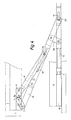
- Fig. 1 of the drawing shows an application example of the invention in tilt-and-turn windows with a frame I and a wing II. Between frame I and wing II, a lower load-bearing scissors 3 and an upper tilt-and-turn scissors 4 are arranged in the air gap 2. The closure 5 in the upper scissors 4 is connected to a central closure, which is shown in Fig. 1 in the closed position.
- the upper scissors 4 is attached to the frame I by the corner bracket 6.
- the support arm 7 and the control arm 8 are rotatably mounted on the corner bracket 6 and have teeth 9, 9a at the ends facing the bracket, which are in engagement with one another.
- the extension arm 10 is rotatably arranged on the support arm 7 and connected to the wing II in a slot 11 of the faceplate or cover rail 12 with the pin 27.
- the extension arm 10 has a slot guide 13 for receiving a guide pin 14 which is arranged on the control arm 8.
- This guide pin 14 penetrates the guide slot 13 in the extension arm 10 and slides during the pivoting movement of the wing II (FIG. 5) in the guide 15, which is also arranged on the cover rail 12 on the wing II.
- the arrangement is such that the guide pin 14 does not engage in the guide 15 when the wing II (FIG. 4) tilts.
- the guide pin 14 is moved into the guide 15 and thus the extension arm 10 is locked with the wing II, so that it is held securely.
- a maloperation lock of the central lock can therefore be dispensed with, since a tilting movement of the wing II is thus excluded from the pivoting position of the wing.
- the guide pin 14 When the wing II tilts, the guide pin 14 does not engage in the guide 15, so that the extension arm 10 around the pin 27 in the guide 11 Rotation and sliding movement experiences, with the result that the upper edge of the wing II moves away from the frame I.
- the extension arm 10 is held by the additional arm 30, which is rotatably arranged on the frame of the wing II and on the extension arm 10.
- the lower scissors 3 has the same kinematics as the upper scissors 4, i. that is, the support arms 7 and 18, the control arms 8 and 19 are of the same length and the teeth 9, 9a and 29, 29a are of the same design.
- the pivot points of the wing on the support arms 7 and 18 are arranged in the rebate area 2 between frame I and wing II such that the connection of these points corresponds to a vertical axis 26 which runs between frame I and wing II.
- the support arm 18 of the lower scissors 3 is mounted on the vertical leg 16 of the angle 17, which is attached to the wing II.
- Such a mounting of the support arm in the case of wing profiles with or without a hardware groove can be used as a supporting corner bearing (FIG. 2).
- the angle 17 has in its horizontal section 24 a guide slot 20, in which a guide pin 25, which is arranged on the control arm 19, engages.
- the support arm 18 and the control arm 19 are rotatably connected to the support plate 22 by the pins 28 and 28a.
- the support arm 18 undergoes a rotational movement in the opposite direction, analogous to the movement of the upper scissors, since the toothings 29 and 29a of the support arm 18 and of the control arm 19 are in engagement with one another.
- Fig. 5 it can be seen that in a pivoting of the wing II in Clockwise direction of the control arm 19 also clockwise, but the support arm 18 is moved in the opposite direction.
- the support plate 22 is tiltably arranged on the screw-on plate 21.
- the support plate 22 can be adjusted in both directions in the horizontal plane by means of two eccentric pins 23.
Landscapes
- Engineering & Computer Science (AREA)
- Mechanical Engineering (AREA)
- Hinges (AREA)
- Extensible Doors And Revolving Doors (AREA)
- Support Devices For Sliding Doors (AREA)
- Wing Frames And Configurations (AREA)
Abstract
Description
Die Erfindung betrifft einen Beschlag, der verdeckt im Falz zwischen Rahmen und Flügel von Schwenkflügeln, insbesondere für Kipp-Schwenkflügel von Fenstern und Türen, angeordnet ist, mit den Merkmalen des Oberbegriffs des Anspruches 1.The invention relates to a fitting, which is concealed in the fold between the frame and the sash of pivoting sashes, in particular for tilt-pivoting sashes of windows and doors, with the features of the preamble of claim 1.
Derartige Beschläge sind in verschiedenen Ausführungen bekannt. Durch die US-Patentschrift 3,838,537 ist ein verdeckt im Falz eingeschraubtes Scherensystem bekannt, welches aber nur bei Schwenkflügeln Anwendung findet, die sehr leicht gebaut sind.Such fittings are known in various designs. US Pat. No. 3,838,537 discloses a scissor system screwed in concealed in the fold, but this system is only used for pivoting wings that are very light in construction.
Diese zum Stand der Technik gehörende Scherenkonstruktion gemäß US-PS 3,838,537 weist einen kurzen Tragarm und einen längeren Steuerarm auf, die mittels einer Verzahnung in gegenseitigem Eingriff stehen.This scissor construction belonging to the state of the art according to US Pat. No. 3,838,537 has a short support arm and a longer control arm, which are in mutual engagement by means of a toothing.
Beide Arme sind auf einem, in einer C-Führungsschiene verschiebbar angeordnetem Gleiter drehbar gelagert. Über einen Verbindungsarm, der einerseits am Flügel und andererseits am Rahmen an der C-Führungsschiene angelenkt ist, wird der längere Steuerarm über die Flügelbewegung angetrieben, so daß der Gleiter in der C-Führungsschiene eine schiebende Bewegung macht und der Steuerarm eine Drehbewegung erfährt.Both arms are rotatably mounted on a slider which is displaceably arranged in a C-guide rail. The longer control arm is driven by the wing movement via a connecting arm, which is articulated on the one hand on the wing and on the other hand on the frame, so that the slider in the C-guide rail makes a pushing movement and the control arm experiences a rotational movement.
Bei dieser Drehbewegung des Steuerarms wird auf den kurzen Tragarm eine gegenläufige Drehbewegung übertragen. Da der kurze Tragarm an der Flügelkante angelenkt ist, wird der Flügel vom Rahmen wegbewegt. Damit wird eine sichere Öffnungs- und Schließbewegung ermöglicht.During this rotational movement of the control arm, an opposite rotational movement is transmitted to the short support arm. Since the short support arm is articulated on the wing edge, the wing is moved away from the frame. This enables a safe opening and closing movement.
Da die Einsatzmöglichkeit des unteren Ecklagers auch für schwere Schwenkflügel erreicht werden soll, die Flügelprofile ohne Beschlagnut aufweisen, müssen alle tragenden Bauteile in der Falzluft zwischen Flügel und Rahmen angeordnet werden.As the lower corner bearing can also be used for heavy pivoting sashes that have sash profiles without a hardware groove, all load-bearing components must be arranged in the rebate clearance between the sash and frame.
Die DE-Patentanmeldung 36 01 278 zeigt ein Ecklager mit einer Riegelnase, daß nur bei Flügelprofilen einsetzbar ist, die eine tiefe Beschlagnut (Euronut) aufweisen. Die verlängerte Achse des Tragarmes greift in eine Verdickung des senkrechten Schenkels ein, die vollständig in der tiefen Beschlagnut (Euronut) liegt.DE patent application 36 01 278 shows a corner bearing with a locking lug that can only be used with wing profiles that have a deep fitting groove (Euronut). The extended axis of the support arm engages in a thickening of the vertical leg, which lies entirely in the deep fitting groove (Euronut).
Es ist Aufgabe der Erfindung, ein verdeckt im Falz eingebautes Ecklager so weiterzuentwickeln, daß es für alle Schwenk- und Schwenk-Kippfenster eingesetzt werden kann. Weiterhin soll eine obere Scherenhalterung so ausgebildet werden, daß, wenn Schwenk-Kippfenster mit Beschlagnut verwendet werden, diese mit dem unteren Ecklager in der Führung des Flügels übereinstimmt.It is an object of the invention to further develop a corner bearing which is concealed in the fold so that it can be used for all pivoting and pivoting-tilting windows. Furthermore, an upper scissor bracket should be designed so that when swivel-tilt windows with hardware groove are used, this matches the lower corner bearing in the guide of the sash.
Diese Aufgabe wird nach den Kennzeichen des Anspruches 1 gelöst. Die Anlenkpunkte der Tragarme am Flügel sind im Falzbereich zwischen Blendrahmen und Flügel angeordnet. Durch die Lagerung des Flügels am senkrechten Schenkel des Winkels in der Falzluft wird eine Verstärkung erreicht, die auch höhere Gewichte des Flügels aufnehmen kann. Auch kann der Tragarm in seiner Abmessung wesentlich kürzer gehalten werden, da der Abstand vom Lagerpunkt am Rahmen zum Lagerpunkt am Flügel bei ca. 90° verschwenktem Flügel kleiner ist, als in der DE-Patentanmeldung 36 01 278.This object is achieved according to the characterizing part of claim 1. The articulation points of the support arms on the sash are arranged in the rebate area between the frame and sash. By mounting the wing on the vertical leg of the angle in the rebate air, a reinforcement is achieved which can also take higher weights of the wing. The support arm can also be kept considerably shorter in size be, since the distance from the bearing point on the frame to the bearing point on the wing is smaller at about 90 ° pivoted wing than in DE patent application 36 01 278.
Die oberen und unteren Trag- und Steuerarme weisen an ihrem am Blendrahmen angebrachten Enden Verzahnungen auf, die miteinander in Eingriff stehen. Der Tragarm, der vom Steuerarm über die Verzahnung bewegt wird, drückt den Flügel sofort vom Rahmen ab.The upper and lower support and control arms have toothings on their ends attached to the frame which are in engagement with one another. The support arm, which is moved by the control arm via the teeth, immediately pushes the sash off the frame.
Durch die unterschiedlichen Zahnkranzdurchmesser der Verzahnungen durchläuft der Steuerarm einen größeren Winkel als der Tragarm mit dem größeren Zahnkranzdurchmesser. Durch diese Konstruktion kann der Flügel bis 90° oder mehr verschwenkt werden, bis Tragarm und Steuerarm aneinanderliegen und einen festen Anschlag für den Flügel bilden.Due to the different ring gear diameter of the gears, the control arm runs through a larger angle than the support arm with the larger ring gear diameter. With this construction, the sash can be swiveled up to 90 ° or more until the support arm and control arm lie against each other and form a fixed stop for the sash.
Durch die Schlitzführung für den Steuerarm der unteren Schere im waagerechten Schenkel des Eckwinkels ist eine genaue Führung des Flügels bei der geringsten Drehbewegung des Flügels gegeben.Due to the slot guide for the control arm of the lower scissors in the horizontal leg of the corner bracket, the wing is guided precisely with the slightest rotational movement of the wing.
Die Abmessungen und die Verzahnungen der oberen Arme entsprechen denen der unteren Arme. Dabei werden die oberen Arme an einem Ausstellarm angebracht. Der Ausstellarm weist ebenfalls eine Schlitzführung für die Aufnahme eines Führungszapfens, der am Steuerarm der oberen Scherenhalterung befestigt ist, auf.The dimensions and the toothing of the upper arms correspond to those of the lower arms. The upper arms are attached to an extension arm. The extension arm also has a slot guide for receiving a guide pin which is attached to the control arm of the upper scissor holder.
Dieser Führungszapfen durchdringt den Schlitz im Ausstellarm und gleitet während der Schwenkbewegung des Flügels in einer Führung, welche auf der Deckschiene am Flügel angebracht ist.This guide pin penetrates the slot in the extension arm and slides during the pivoting movement of the wing in a guide which is attached to the cover rail on the wing.
Durch die Konstruktion wird der Flügel während der Schwenkbewegung sicher gehalten. Sollte durch den Zentralverschluß eine Fehlbedienung geschaltet werden, bleibt diese wirkungslos, da die Ausstellschere durch den Führungszapfen am Flügel gehalten wird, so daß keine Kippbewegung möglich ist. Wird hingegen eine Kippstellung durch den Zentralverschluß bewirkt, ist dieser Führungszapfen nicht im Eingriff mit der Führung, so daß eine Kippbewegung ermöglicht wird.The construction holds the wing securely during the swiveling movement. If incorrect operation is switched by the central lock, this remains ineffective since the stay scissors are held by the guide pin on the wing, so that no tilting movement is possible. If, on the other hand, a tilting position is brought about by the central lock, this guide pin is not in engagement with the guide, so that a tilting movement is made possible.
Das untere Ecklager weist vorzugsweise eine Anschraubplatte und eine Stützplatte auf, die auf der Anschraubplatte kippbar angeordnet ist. Durch Excenterschrauben kann eine Regulierung dieses Lagers in zwei Richtungen vorgenommen werden, ohne die Kippeigenschaft zu beeinträchtigen. Auch ist eine bessere Aus- und Einhängenöglichkeit gegeben.The lower corner bearing preferably has a screw-on plate and a support plate which is tiltably arranged on the screw-on plate. Eccentric screws can be used to regulate this bearing in two directions without affecting the tilting properties. There is also a better way of hanging and unhooking.
Anhand der Zeichnung wird der Gegenstand der Erfindung erläutert. Es zeigen:
- Fig. 1 Seitenansicht des in der Falzluft zwischen Rahmen und Flügel verdeckt angeordneten Scherensystems,
- Fig. 2 Querschnitte von Flügelprofilen mit und ohne Beschlagnut,
- Fig. 3 Draufsicht der Anschraubplatte und der Stützplatte der unteren Schere mit Excenterzapfen,
- Fig. 4 Draufsicht der oberen Schere bei gekipptem Flügel eines Drehkippfensters,
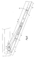
- Fig. 5 Draufsicht der oberen Schere bei geschwenktem Flügel eines Drehkippfensters und
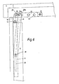
- Fig. 6 Draufsicht der unteren Schere bei geschwenktem Flügel eines Drehkippfensters.
- 1 side view of the scissors system, which is concealed in the rebate air between frame and sash,
- 2 cross sections of wing profiles with and without hardware groove,
- 3 top view of the screw-on plate and the support plate of the lower scissors with eccentric pins,
- 4 top view of the upper scissors with the sash of a tilt and turn window,
- Fig. 5 top view of the upper scissors with pivoted wing of a tilt and turn window
- Fig. 6 top view of the lower scissors with pivoted sash of a tilt and turn window.
Fig. 1 der Zeichnung zeigt als Anwendungsbeispiel die Erfindung bei Drehkippfenstern mit einem Blendrahmen I und einem Flügel II. Zwischen Blendrahmen I und Flügel II ist in der Falzluft 2 eine untere tragende Schere 3 und eine obere Drehkippschere 4 angeordnet. Der Verschluß 5 bei der oberen Schere 4 ist mit einem Zentralverschluß verbunden, der in Fig. 1 in geschlossener Stellung gezeigt ist.Fig. 1 of the drawing shows an application example of the invention in tilt-and-turn windows with a frame I and a wing II. Between frame I and wing II, a lower load-bearing
Die obere Schere 4 ist an dem Blendrahmen I durch den Eckwinkel 6 befestigt. Der Tragarm 7 und der Steuerarm 8 sind auf dem Eckwinkel 6 drehbar angebracht und weisen an den dem Winkel zugekehrten Enden Verzahnungen 9, 9a auf, die miteinander in Eingriff sind. Der Ausstellarm 10 ist an dem Tragarm 7 drehbar angeordnet und mit dem Flügel II in einem Langschlitz 11 der Stulp- oder Deckschiene 12 mit dem Zapfen 27 verbunden. Der Ausstellarm 10 weist eine Schlitzführung 13 für die Aufnahme eines Führungszapfens 14, der an dem Steuerarm 8 angeordnet ist, auf.The upper scissors 4 is attached to the frame I by the
Dieser Führungszapfen 14 durchdringt den Führungsschlitz 13 im Ausstellarm 10 und gleitet während der Schwenkbewegung des Flügels II (Fig. 5) in der Führung 15, die ebenfalls auf der Deckschiene 12 am Flügel II angeordnet ist. Die Anordnung ist dabei so getroffen, daß der Führungszapfen 14 bei einer Kippbewegung des Flügels II (Fig. 4) nicht in die Führung 15 eingreift. Während der Schwenkbewgung des Flügels (Fig. 5) hingegen wird der Führungszapfen 14 in die Führung 15 bewegt und damit der Ausstellarm 10 mit dem Flügel II arretiert, so daß dieser sicher gehalten ist. Auf eine Fehlbedienungssperre des Zentralverschlusses kann daher verzichtet werden, da eine Kippbewegung des Flügels II somit aus der Schwenkstellung des Flügels ausgeschlossen ist. Bei einer Kippbewegung des Flügels II greift der Führungszapfen 14 nicht in die Führung 15 ein, so daß der Ausstellarm 10 um den Zapfen 27 in der Führung 11 eine Dreh- und Schiebebewegung erfährt, mit der Folge, daß sich die obere Kante des Flügels II vom Blendrahmen I wegbewegt. Der Ausstellarm 10 wird dabei durch den Zusatzarm 30, der am Rahmen des Flügels II und am Ausstellarm 10 drehbar angeordnet ist, gehalten.This
Die untere Schere 3 weist die gleiche Kinematik wie die obere Schere 4 auf, d. h., daß die Tragarme 7 und 18, die Steuerarme 8 und 19 gleich lang und Verzahnungen 9, 9a und 29, 29a gleichartig ausgebildet sind. Die Anlenkpunkte des Flügels an die Tragarme 7 und 18 sind im Falzbereich 2 zwischen Blendrahmen I und Flügel II derart angeordnet, daß die Verbindung dieser Punkte einer senkrechten Achse 26 entspricht, die zwischen Blendrahmen I und Flügel II verläuft. In dieser Achse 26 ist der Tragarm 18 der unteren Schere 3 am senkrechten Schenkel 16 des Winkels 17, der am Flügel II angebracht ist, gelagert.The
Als tragendes Ecklager kann eine derartige Lagerung des Tragarms bei Flügelprofilen mit oder ohne Beschlagnut verwendet werden (Fig. 2).Such a mounting of the support arm in the case of wing profiles with or without a hardware groove can be used as a supporting corner bearing (FIG. 2).
Der Winkel 17 weist in seinem waagerechten Abschnitt 24 einen Führungsschlitz 20 auf, in welchem ein Führungszapfen 25, der am Steuerarm 19 angeordnet ist, eingreift. Der Tragarm 18 und der Steuerarm 19 sind mit der Stützplatte 22 durch die Zapfen 28 bzw. 28a drehbar verbunden. Bei einer Schwenkbewegung des Flügels erfährt demnach der Tragarm 18, analog zum Bewegungsablauf der oberen Schere, eine Drehbewegung in entgegengesetzter Richtung, da die Verzahnungen 29 und 29a des Tragarms 18 bzw. des Steuerarms 19 miteinander in Eingriff sind. Insbesondere in Fig. 5 ist ersichtlich, daß bei einer Verschwenkung des Flügels II in Uhrzeigerrichtung der Steuerarm 19 auch in Uhrzeigerrichtung, der Tragarm 18 jedoch entgegengesetzt bewegt wird.The
Die Stützplatte 22 ist auf der Anschraubplatte 21 kippbar angeordnet. Durch zwei Excenterzapfen 23 ist die Stützplatte 22 in beiden Richtungen in horizontaler Ebene verstellbar.The
Claims (8)
Priority Applications (3)
| Application Number | Priority Date | Filing Date | Title |
|---|---|---|---|
| EP89117356A EP0419687B1 (en) | 1989-09-20 | 1989-09-20 | Concealed stay for turning and tiltable windows or doors |
| DE8989117356T DE58905179D1 (en) | 1989-09-20 | 1989-09-20 | HIDDEN IN THE FOLDED EXHIBITION DEVICE FOR Tilt-and-pivot sash of windows or doors. |
| AT89117356T ATE92579T1 (en) | 1989-09-20 | 1989-09-20 | OPENING DEVICE CONCEALED IN THE REBATE FOR TILT-SWIVEL SASHES OF WINDOWS OR DOORS. |
Applications Claiming Priority (1)
| Application Number | Priority Date | Filing Date | Title |
|---|---|---|---|
| EP89117356A EP0419687B1 (en) | 1989-09-20 | 1989-09-20 | Concealed stay for turning and tiltable windows or doors |
Publications (2)
| Publication Number | Publication Date |
|---|---|
| EP0419687A1 true EP0419687A1 (en) | 1991-04-03 |
| EP0419687B1 EP0419687B1 (en) | 1993-08-04 |
Family
ID=8201908
Family Applications (1)
| Application Number | Title | Priority Date | Filing Date |
|---|---|---|---|
| EP89117356A Expired - Lifetime EP0419687B1 (en) | 1989-09-20 | 1989-09-20 | Concealed stay for turning and tiltable windows or doors |
Country Status (3)
| Country | Link |
|---|---|
| EP (1) | EP0419687B1 (en) |
| AT (1) | ATE92579T1 (en) |
| DE (1) | DE58905179D1 (en) |
Cited By (12)
| Publication number | Priority date | Publication date | Assignee | Title |
|---|---|---|---|---|
| GB2276915A (en) * | 1993-03-19 | 1994-10-12 | Ronald Percival Davis | Friction stay with geared pivotal connection |
| GB2279695A (en) * | 1993-07-09 | 1995-01-11 | Peter Winston Lambert | Window stays |
| EP0570945B1 (en) * | 1992-05-20 | 1996-02-28 | W. Hautau Gmbh | Concealed hinge |
| US5775028A (en) * | 1993-07-09 | 1998-07-07 | Lambert; Peter Winston | Window stays |
| DE4129833C2 (en) * | 1991-09-05 | 2000-07-06 | Mila Hardware Ltd | Fitting for tilt and swing casement windows |
| US6374544B1 (en) | 2000-09-18 | 2002-04-23 | Frederick Ellis | Window actuator for casement type window |
| EP1568839A2 (en) * | 2004-02-25 | 2005-08-31 | Aug. Winkhaus GmbH & Co. KG | Window or door |
| DE102010000675A1 (en) * | 2010-01-05 | 2011-07-07 | Aug. Winkhaus GmbH & Co. KG, 48291 | Corner bearing of a wing pivotable against a frame of a window and window with such a corner bearing |
| DE202010014477U1 (en) * | 2010-10-19 | 2012-01-20 | Maco Technologie Gmbh | fitting assembly |
| ITMI20111106A1 (en) * | 2011-06-20 | 2012-12-21 | Masterlab S R L Unipersonale | "RETRACTABLE HINGING SYSTEM FOR EXAMPLE FOR DOORS, WINDOWS OR FLAPS" |
| EP2703587A3 (en) * | 2012-08-28 | 2014-12-10 | Wilh. Schlechtendahl & Söhne GmbH & Co. KG | Fitting for concealed assembly in the rabbet between a wing and a frame of a window, a door or the like |
| WO2016059524A1 (en) * | 2014-10-14 | 2016-04-21 | Ermenegildo Sossai | Window assembly having concealed hinges |
Citations (3)
| Publication number | Priority date | Publication date | Assignee | Title |
|---|---|---|---|---|
| FR1473121A (en) * | 1965-01-07 | 1967-03-17 | Schuermann & Co Heinz | Swivel, tilt-tilt, tilt or bellows frame, for windows or doors |
| US3838537A (en) * | 1973-07-02 | 1974-10-01 | Truth Inc | Window hinge |
| DE8902682U1 (en) * | 1989-03-06 | 1989-05-24 | W. Hautau GmbH, 3068 Helpsen | Concealed fitting with rebate for tilt-and-turn windows or doors etc. |
Family Cites Families (2)
| Publication number | Priority date | Publication date | Assignee | Title |
|---|---|---|---|---|
| DE3601278C3 (en) * | 1986-01-17 | 1997-11-13 | Hautau Gmbh W | Hidden fitting for swivel bearings, especially for tilt-swivel sashes of windows or doors |
| US5081741A (en) * | 1988-10-11 | 1992-01-21 | Ferco International Usine De Ferrures De Batiment | Hinge fittings for pivoting and tiltable doors, windows or the like, situated in rabbets of the opening frame and the fixed frame |
-
1989
- 1989-09-20 AT AT89117356T patent/ATE92579T1/en not_active IP Right Cessation
- 1989-09-20 EP EP89117356A patent/EP0419687B1/en not_active Expired - Lifetime
- 1989-09-20 DE DE8989117356T patent/DE58905179D1/en not_active Expired - Fee Related
Patent Citations (3)
| Publication number | Priority date | Publication date | Assignee | Title |
|---|---|---|---|---|
| FR1473121A (en) * | 1965-01-07 | 1967-03-17 | Schuermann & Co Heinz | Swivel, tilt-tilt, tilt or bellows frame, for windows or doors |
| US3838537A (en) * | 1973-07-02 | 1974-10-01 | Truth Inc | Window hinge |
| DE8902682U1 (en) * | 1989-03-06 | 1989-05-24 | W. Hautau GmbH, 3068 Helpsen | Concealed fitting with rebate for tilt-and-turn windows or doors etc. |
Cited By (15)
| Publication number | Priority date | Publication date | Assignee | Title |
|---|---|---|---|---|
| DE4129833C2 (en) * | 1991-09-05 | 2000-07-06 | Mila Hardware Ltd | Fitting for tilt and swing casement windows |
| EP0570945B1 (en) * | 1992-05-20 | 1996-02-28 | W. Hautau Gmbh | Concealed hinge |
| GB2276915B (en) * | 1993-03-19 | 1996-11-27 | Ronald Percival Davis | A window stay |
| GB2276915A (en) * | 1993-03-19 | 1994-10-12 | Ronald Percival Davis | Friction stay with geared pivotal connection |
| GB2279695B (en) * | 1993-07-09 | 1997-06-04 | Peter Winston Lambert | Window stays |
| US5775028A (en) * | 1993-07-09 | 1998-07-07 | Lambert; Peter Winston | Window stays |
| GB2279695A (en) * | 1993-07-09 | 1995-01-11 | Peter Winston Lambert | Window stays |
| US6374544B1 (en) | 2000-09-18 | 2002-04-23 | Frederick Ellis | Window actuator for casement type window |
| EP1568839A2 (en) * | 2004-02-25 | 2005-08-31 | Aug. Winkhaus GmbH & Co. KG | Window or door |
| EP1568839A3 (en) * | 2004-02-25 | 2013-04-10 | Aug. Winkhaus GmbH & Co. KG | Window or door |
| DE102010000675A1 (en) * | 2010-01-05 | 2011-07-07 | Aug. Winkhaus GmbH & Co. KG, 48291 | Corner bearing of a wing pivotable against a frame of a window and window with such a corner bearing |
| DE202010014477U1 (en) * | 2010-10-19 | 2012-01-20 | Maco Technologie Gmbh | fitting assembly |
| ITMI20111106A1 (en) * | 2011-06-20 | 2012-12-21 | Masterlab S R L Unipersonale | "RETRACTABLE HINGING SYSTEM FOR EXAMPLE FOR DOORS, WINDOWS OR FLAPS" |
| EP2703587A3 (en) * | 2012-08-28 | 2014-12-10 | Wilh. Schlechtendahl & Söhne GmbH & Co. KG | Fitting for concealed assembly in the rabbet between a wing and a frame of a window, a door or the like |
| WO2016059524A1 (en) * | 2014-10-14 | 2016-04-21 | Ermenegildo Sossai | Window assembly having concealed hinges |
Also Published As
| Publication number | Publication date |
|---|---|
| ATE92579T1 (en) | 1993-08-15 |
| EP0419687B1 (en) | 1993-08-04 |
| DE58905179D1 (en) | 1993-09-09 |
Similar Documents
| Publication | Publication Date | Title |
|---|---|---|
| EP0065109B1 (en) | Hinge | |
| EP0419687B1 (en) | Concealed stay for turning and tiltable windows or doors | |
| AT402086B (en) | FITTING FOR DOORS, WINDOWS OR THE LIKE | |
| DE8513538U1 (en) | Fitting for an at least parallel adjustable and displaceable sash of a window, door or the like. | |
| DE3904210C2 (en) | ||
| DE3343366C2 (en) | ||
| DE2443866A1 (en) | DEVICE FOR SECURING THE POSITION OF THE EXTENDING ARM OF EXHIBITION DEVICES FOR WINDOWS, DOORS OR THE LIKE. | |
| EP0542050B1 (en) | Fitting for over 180 degrees towards inside or outside turnable window wings or similar | |
| DE2529084C2 (en) | Door holder connected to a door hinge | |
| DE2534203A1 (en) | Lock for tilting and rotating windows - has hook lever preventing wrong actuation or inadvertent closing | |
| DE2419842B2 (en) | Closing slide for turn-tilt windows | |
| EP0487825A1 (en) | Hidden fittings for pivoting wings, especially for turning and tiltable wings, of windows or doors | |
| DE2505511C3 (en) | Overlying skylight opener | |
| DE1584084A1 (en) | Opening device for tilt and turn windows | |
| DE1784611A1 (en) | Opening device for swivel and tilt windows, doors or the like. | |
| DE3148555C2 (en) | ||
| DE1559736A1 (en) | Pressure and pressure device for the wing of tilt-swivel windows, doors or the like. | |
| EP0495198A1 (en) | Door check, especially for tilt and turn windows | |
| DE2010406B2 (en) | Stay for rotating and tilting window or door - has link to window locking levers provided by projecting locking arm | |
| DE1584081C3 (en) | Opening device for turn-tilt windows, doors or the like | |
| DE9116309U1 (en) | Fitting for tilting and parallel sliding sashes | |
| DE2531084A1 (en) | Tilting window stay mechanism - has swivelling stay arm with set off part fitting into base plate recess | |
| DE69002490T2 (en) | Bearings for swing or swing roof windows. | |
| DE3915796A1 (en) | Opening-out device for side/bottom hung sashes | |
| DE2552939A1 (en) | Lock for rotating and tilting windows - has arm with extension for foolproof operation and open window stabilisation |
Legal Events
| Date | Code | Title | Description |
|---|---|---|---|
| PUAI | Public reference made under article 153(3) epc to a published international application that has entered the european phase |
Free format text: ORIGINAL CODE: 0009012 |
|
| AK | Designated contracting states |
Kind code of ref document: A1 Designated state(s): AT BE CH DE ES FR GB GR IT LI LU NL SE |
|
| 17P | Request for examination filed |
Effective date: 19911001 |
|
| 17Q | First examination report despatched |
Effective date: 19920124 |
|
| GRAA | (expected) grant |
Free format text: ORIGINAL CODE: 0009210 |
|
| AK | Designated contracting states |
Kind code of ref document: B1 Designated state(s): AT BE CH DE ES FR GB GR IT LI LU NL SE |
|
| PG25 | Lapsed in a contracting state [announced via postgrant information from national office to epo] |
Ref country code: SE Effective date: 19930804 Ref country code: NL Effective date: 19930804 Ref country code: GR Free format text: LAPSE BECAUSE OF FAILURE TO SUBMIT A TRANSLATION OF THE DESCRIPTION OR TO PAY THE FEE WITHIN THE PRESCRIBED TIME-LIMIT Effective date: 19930804 Ref country code: FR Effective date: 19930804 Ref country code: ES Free format text: THE PATENT HAS BEEN ANNULLED BY A DECISION OF A NATIONAL AUTHORITY Effective date: 19930804 Ref country code: BE Effective date: 19930804 |
|
| REF | Corresponds to: |
Ref document number: 92579 Country of ref document: AT Date of ref document: 19930815 Kind code of ref document: T |
|
| REF | Corresponds to: |
Ref document number: 58905179 Country of ref document: DE Date of ref document: 19930909 |
|
| GBT | Gb: translation of ep patent filed (gb section 77(6)(a)/1977) |
Effective date: 19930831 |
|
| PG25 | Lapsed in a contracting state [announced via postgrant information from national office to epo] |
Ref country code: LU Free format text: LAPSE BECAUSE OF NON-PAYMENT OF DUE FEES Effective date: 19930930 Ref country code: LI Effective date: 19930930 Ref country code: CH Effective date: 19930930 |
|
| ITF | It: translation for a ep patent filed | ||
| EN | Fr: translation not filed | ||
| NLV1 | Nl: lapsed or annulled due to failure to fulfill the requirements of art. 29p and 29m of the patents act | ||
| REG | Reference to a national code |
Ref country code: CH Ref legal event code: PL |
|
| PLBE | No opposition filed within time limit |
Free format text: ORIGINAL CODE: 0009261 |
|
| STAA | Information on the status of an ep patent application or granted ep patent |
Free format text: STATUS: NO OPPOSITION FILED WITHIN TIME LIMIT |
|
| 26N | No opposition filed | ||
| REG | Reference to a national code |
Ref country code: GB Ref legal event code: IF02 |
|
| PGFP | Annual fee paid to national office [announced via postgrant information from national office to epo] |
Ref country code: AT Payment date: 20020925 Year of fee payment: 14 |
|
| PGFP | Annual fee paid to national office [announced via postgrant information from national office to epo] |
Ref country code: GB Payment date: 20021001 Year of fee payment: 14 |
|
| PGFP | Annual fee paid to national office [announced via postgrant information from national office to epo] |
Ref country code: DE Payment date: 20021125 Year of fee payment: 14 |
|
| PG25 | Lapsed in a contracting state [announced via postgrant information from national office to epo] |
Ref country code: GB Free format text: LAPSE BECAUSE OF NON-PAYMENT OF DUE FEES Effective date: 20030920 Ref country code: AT Free format text: LAPSE BECAUSE OF NON-PAYMENT OF DUE FEES Effective date: 20030920 |
|
| PG25 | Lapsed in a contracting state [announced via postgrant information from national office to epo] |
Ref country code: DE Free format text: LAPSE BECAUSE OF NON-PAYMENT OF DUE FEES Effective date: 20040401 |
|
| GBPC | Gb: european patent ceased through non-payment of renewal fee |
Effective date: 20030920 |
|
| PG25 | Lapsed in a contracting state [announced via postgrant information from national office to epo] |
Ref country code: IT Free format text: LAPSE BECAUSE OF NON-PAYMENT OF DUE FEES Effective date: 20050920 |