EP0460422B1 - Pivot bearing, especially for wings of windows, doors or similar - Google Patents
Pivot bearing, especially for wings of windows, doors or similar Download PDFInfo
- Publication number
- EP0460422B1 EP0460422B1 EP91107606A EP91107606A EP0460422B1 EP 0460422 B1 EP0460422 B1 EP 0460422B1 EP 91107606 A EP91107606 A EP 91107606A EP 91107606 A EP91107606 A EP 91107606A EP 0460422 B1 EP0460422 B1 EP 0460422B1
- Authority
- EP
- European Patent Office
- Prior art keywords
- support arm
- wing
- panel
- pivot
- drive member
- Prior art date
- Legal status (The legal status is an assumption and is not a legal conclusion. Google has not performed a legal analysis and makes no representation as to the accuracy of the status listed.)
- Expired - Lifetime
Links
- 230000002093 peripheral effect Effects 0.000 claims description 11
- 238000006073 displacement reaction Methods 0.000 claims description 5
- 230000000717 retained effect Effects 0.000 claims 1
- 238000007789 sealing Methods 0.000 description 2
- 238000005452 bending Methods 0.000 description 1
- 230000008878 coupling Effects 0.000 description 1
- 238000010168 coupling process Methods 0.000 description 1
- 238000005859 coupling reaction Methods 0.000 description 1
- 230000000694 effects Effects 0.000 description 1
- 238000005516 engineering process Methods 0.000 description 1
- 238000003780 insertion Methods 0.000 description 1
- 230000037431 insertion Effects 0.000 description 1
- 238000004519 manufacturing process Methods 0.000 description 1
- 238000000034 method Methods 0.000 description 1
- 125000006850 spacer group Chemical group 0.000 description 1
Images

Classifications
-
- E—FIXED CONSTRUCTIONS
- E05—LOCKS; KEYS; WINDOW OR DOOR FITTINGS; SAFES
- E05D—HINGES OR SUSPENSION DEVICES FOR DOORS, WINDOWS OR WINGS
- E05D7/00—Hinges or pivots of special construction
- E05D7/08—Hinges or pivots of special construction for use in suspensions comprising two spigots placed at opposite edges of the wing, especially at the top and the bottom, e.g. trunnions
- E05D7/081—Hinges or pivots of special construction for use in suspensions comprising two spigots placed at opposite edges of the wing, especially at the top and the bottom, e.g. trunnions the pivot axis of the wing being situated near one edge of the wing, especially at the top and bottom, e.g. trunnions
-
- E—FIXED CONSTRUCTIONS
- E05—LOCKS; KEYS; WINDOW OR DOOR FITTINGS; SAFES
- E05D—HINGES OR SUSPENSION DEVICES FOR DOORS, WINDOWS OR WINGS
- E05D7/00—Hinges or pivots of special construction
- E05D7/04—Hinges adjustable relative to the wing or the frame
- E05D7/0415—Hinges adjustable relative to the wing or the frame with adjusting drive means
- E05D7/0423—Screw-and-nut mechanisms
-
- E—FIXED CONSTRUCTIONS
- E05—LOCKS; KEYS; WINDOW OR DOOR FITTINGS; SAFES
- E05D—HINGES OR SUSPENSION DEVICES FOR DOORS, WINDOWS OR WINGS
- E05D7/00—Hinges or pivots of special construction
- E05D7/04—Hinges adjustable relative to the wing or the frame
- E05D2007/0469—Hinges adjustable relative to the wing or the frame in an axial direction
-
- E—FIXED CONSTRUCTIONS
- E05—LOCKS; KEYS; WINDOW OR DOOR FITTINGS; SAFES
- E05D—HINGES OR SUSPENSION DEVICES FOR DOORS, WINDOWS OR WINGS
- E05D7/00—Hinges or pivots of special construction
- E05D7/04—Hinges adjustable relative to the wing or the frame
- E05D2007/0484—Hinges adjustable relative to the wing or the frame in a radial direction
-
- E—FIXED CONSTRUCTIONS
- E05—LOCKS; KEYS; WINDOW OR DOOR FITTINGS; SAFES
- E05Y—INDEXING SCHEME ASSOCIATED WITH SUBCLASSES E05D AND E05F, RELATING TO CONSTRUCTION ELEMENTS, ELECTRIC CONTROL, POWER SUPPLY, POWER SIGNAL OR TRANSMISSION, USER INTERFACES, MOUNTING OR COUPLING, DETAILS, ACCESSORIES, AUXILIARY OPERATIONS NOT OTHERWISE PROVIDED FOR, APPLICATION THEREOF
- E05Y2900/00—Application of doors, windows, wings or fittings thereof
- E05Y2900/10—Application of doors, windows, wings or fittings thereof for buildings or parts thereof
- E05Y2900/13—Type of wing
- E05Y2900/132—Doors
-
- E—FIXED CONSTRUCTIONS
- E05—LOCKS; KEYS; WINDOW OR DOOR FITTINGS; SAFES
- E05Y—INDEXING SCHEME ASSOCIATED WITH SUBCLASSES E05D AND E05F, RELATING TO CONSTRUCTION ELEMENTS, ELECTRIC CONTROL, POWER SUPPLY, POWER SIGNAL OR TRANSMISSION, USER INTERFACES, MOUNTING OR COUPLING, DETAILS, ACCESSORIES, AUXILIARY OPERATIONS NOT OTHERWISE PROVIDED FOR, APPLICATION THEREOF
- E05Y2900/00—Application of doors, windows, wings or fittings thereof
- E05Y2900/10—Application of doors, windows, wings or fittings thereof for buildings or parts thereof
- E05Y2900/13—Type of wing
- E05Y2900/148—Windows
Definitions
- the invention relates to a pivot bearing, in particular for the sash of windows, doors or the like, which is installed between the circumferential surfaces directed transversely to the sash and frame level, primarily the sash and frame rebate circumferential surfaces, consisting of one in a plane transverse to the axial direction of a pivot joint extending wing rail and a frame part, between which the pivot joint is provided, wherein, in the assembled state of the bearing, the wing parallel to its plane, relative to the pivot joint, by means of one hand on the wing rail and on the other hand on one Joint part attacking actuator, for example a screw, can be adjusted to a limited extent, the joint part being formed by a support arm which is arranged between the wing rail and the frame part and is adjustable in its longitudinal direction and which extends via a further actuator also transversely to its longitudinal direction in a direction transverse to the axial direction of the pivot joint Level is displaceable in connection with the wing rail.
- a pivot bearing in particular for the sash of windows, doors
- a pivot locator of this type is known from US-A-2 530 331.
- the support arm here is pivotally engaged in the immediate vicinity of the pivot joint with the wing rail and engages at its end remote from the pivot joint with the actuator mounted on the wing.
- the invention aims to create a pivot bearing of the type mentioned at the beginning , which combines at least two different adjustment options for the sash in itself with little additional effort and, in the opening position of the sash, allows simple and reliable actuation, in which the different directions of action of the actuators to influence the relative position of the sash rail and frame part relative to one another are of a sufficient magnitude lets use.
- a pivot bearing which takes these demands and wishes into account, but nevertheless has a simple design in terms of production technology, is characterized according to the invention essentially by that the support arm arranged on the frame part, which consists of a frame rail, on the one hand, with its end remote from the pivot joint, engages in a pivotable manner on an axis which - via a slide or the like - can be moved longitudinally along the wing rail by means of the actuator, for example a screw, while it on the other hand, is supported at a point located between the pivot joint and the swivel bearing axis via the further actuator on the wing rail.
- the actuator for example a screw
- the frame part of the pivot bearing can be formed, for example, by a frame rail.
- the invention provides on the one hand that the further actuator is provided between the wing rail and the support arm with direction of action transversely to the pivot bearing axis or parallel to the pivot plane of the support arm, so that it enables the position adjustment of the wing relative to the support arm normal to its plane.
- the further actuator between the wing rail and the support arm can also be arranged with an effective direction parallel to the pivot bearing axis or transversely to the pivot plane of the support arm, which then enables position adjustment of the wing in its plane, but in a direction perpendicular to the first adjustment direction.
- the three-dimensional adjustment possibility for a trunnion bearing according to the invention only presupposes that the above-described further actuators, which are provided individually, are used jointly or simultaneously.
- the - the wing adjustment transverse to its plane - further actuator consist of a stiffly rotatably mounted eccentric, which sits on the wing rail or the support arm and engages in a longitudinal slot of the support arm or the wing rail, the eccentric on it the frame rail facing end face a tool engagement, z. B. has a hexagon to its rotary adjustment, which is accessible in the open position of the wing.
- the - the vertical adjustment of the wing parallel to its plane - other actuator can attack according to the invention on a transverse to the pivot plane of the support arm on the wing rail pressure piece on the support arm, advantageously in such a way that the further actuator is formed by a pressure screw and the pressure piece consists of a slide.
- the pressure screw is advantageously screw-displaceably accommodated in a nut arranged in a fixed manner on the wing rail and engages at the end facing it of the slide which is held and guided by a collar bolt on the wing rail.
- a screw only rotatably in a fixed abutment on the wing rail and to have it engage in a thread on the end of the slide which is held and guided on the wing rail and faces it.
- At least the wing rail is designed as an angle rail, on one leg of which the further actuator for displacing the support arm is arranged in its pivoting plane, while on the other leg the actuator for displacing the support arm is transverse to its swivel plane.
- a particularly high utility value of the pivot bearing results according to the invention by their assignment to a multi-leaf window without an intermediate post in the frame, such that the bearing axis formed by two mirror-inverted pivot bearings and parallel to the spar of the wing they carry conceals along the one carrying a locking device - overlapping - the spar of the neighboring wing runs and is preferably about the same with its peripheral circumferential surface on one level.
- a multi-wing window 1 designed as a three-wing window, which comprises the fixed frame 2 and two side wings 3 and 4 and a middle wing 5.
- the fixed frame 2 is designed without vertical intermediate posts. When in the closed position on the fixed frame 1 sashes 3, 4 and 5 therefore their mutually adjacent, upright wing spars 6 and 7 or 8 and 9 interact directly to bring about the tight closure of the multi-sash window 1 at the relevant points.
- the upright wing spars 6 and 7 of the left side wing 3 and the middle wing 5 are assigned to each other, while on the other hand the upright wing spars 8 and 9 of the middle wing 5 and of the right side wing 4 come into direct connection with one another.
- the left side wing 3 and the right side wing 4 of the multi-sash window 1 are each designed as so-called sash sashes, each of which carries a so-called impact bar 22 or 23 on its upright wing spars 6 and 9, respectively, with which they engage on the upright wing spars 7 and 8 of the middle wing 5 come to the sealing pad. Consequently, the middle wing 5 is designed in relation to the two side wings 3 and 4 as a so-called underlapping wing.
- All of the sashes 3 to 5 of the multi-sash window 1 can be attached to the fixed frame 2 as pure rotating sashes.
- the side wings 3 and 4 of the multi-wing window 1 can also be attached to the fixed frame 2 as so-called tilt and turn sashes.
- the middle wing 5 is only ever provided as a pure rotating wing.
- the middle wing 5 interacts with the horizontal frame spars 20 and 21 of the fixed frame 2, each via pivot bearings 24 and 25, which in the embodiment according to FIG. 1 in the area of the upright wing spar 7 is hidden between the folded peripheral surfaces of the fixed frame 1 and the left side wing 3 and of the middle wing 5 are housed.
- pivot bearings 24 and 25 adjacent to the upright wing spar 8 of the middle wing 5 between the folded peripheral surfaces of the fixed frame 2 and the middle wing 5 and the right side wing 4.
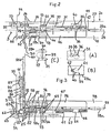
- FIG. 2 The structure and mode of operation of the pivot bearing 24 are shown in FIG. 2, while the structure and mode of operation of the pivot bearing 25 are shown in FIG. 3 of the drawing.
- the - upper - pivot bearing 24 shown in FIG. 2 is fastened, for example screwed, by means of a frame rail 26 to the fold circumferential surface 27 of the upper, horizontal frame spar 20 oriented transversely to the frame plane of the fixed frame 2.
- a wing rail 28 strikes the middle wing 5 at least on the peripheral circumferential surface 29 of the upper, horizontal wing spar 16.
- the wing rail 28 is preferably designed as an angle rail 28a / 28b and is also fastened to the upright wing spar 7 of the middle wing 5 with the rebate peripheral surface 30.
- the leg 28a of the angle rail 28a / 28b bears against the circumferential surface 29 of the fold and the leg 28b bears against the circumferential surface 30 of the middle wing 5.
- a support arm 31 is provided, which is at its one end 32 via a pin joint 33 with the frame rail 26 in a pivotally movable connection.
- the pin joint 33 is directed transversely to the plane of the frame rail 26 and also transversely to the plane of the leg 28a of the wing rail 28, the main plane of the support arm 31 extending transversely to the axial direction of the pin joint 33.
- the support arm 31 is connected to the wing rail 28, specifically with its horizontal leg 28a, and thereby forms the actual joint part of the pivot bearing 24.
- the releasable connection between the leg 28a of the wing rail 28 and the support arm 31 are useful two bolts 34 and 35, which are each seated on the leg 28a of the wing rail 28 as shown in FIG. 2 and are brought into releasable engagement with openings 36 and 37 in the support arm 31, respectively can.
- the opening 36 has - according to the additional illustration (A) of FIG. 2 - an approximately circularly limited
- the bolt 34 has a matching head part 40 with a circularly delimited area 41 and a subsequent radial nose 42, as can be seen in the additional sketch (B) for FIG. 2.
- the opening 37 in the support arm 31 has the shape of a longitudinal slot, while the bolt 35 that comes into engagement therewith has a circularly delimited head part 43, which adjoins its shaft 44 eccentrically.
- the bolt 35 is rotatably mounted in the leg 28a of the wing rail 28 and has a tool engagement 45, for example a hexagon socket, on the end for its actuation.
- a tool engagement 45 for example a hexagon socket
- the support arm 31 can be moved with the wing rail 28 simply by a displacement movement transverse to it Engage and disengage the plane. To secure the engagement connection, it is only necessary to turn the bolt 34 to such an extent that the radial nose 42 of its head part 40 reaches the area of the radial expansion slot 39 in the opening 36 of the support arm 31.
- the bolt 34 is located on the leg 28a of the wing rail 28, it is seated on a carriage 46 which is guided in a longitudinally sliding manner on the underside of the leg 28a of the wing rail 28.
- the pin 34 extends through a longitudinal slot 47 in the leg 28a of the wing rail 28, which is also useful for the sliding guide of the slide 46.
- the carriage 46 is received by a groove 48, as is usually provided on window or door sashes for receiving espagnolette fittings.
- the carriage 46 contains in its end facing the corner region of the wing rail 28 an internal thread 49 which extends parallel to its sliding direction and with which the shaft 50 is engaged by a screw 51 which, although rotatable but non-displaceably anchored in the longitudinal direction, is anchored to the wing rail 28.
- the screw 51 has a tool engagement 52, for example a hexagon socket, which is accessible through a hole 53 in the leg 28b of the wing rail 28.
- a tool engagement 52 for example a hexagon socket
- the slide 46 By turning the screw 51 by means of an actuating tool, for example a hexagon socket wrench, the slide 46 can be moved longitudinally on the underside of the leg 28a of the wing rail 28. In this way it is therefore possible to continuously adjust the central wing 5 parallel to its plane relative to the pivot joint 33 to an extent limited by the longitudinal slot 47. Depending on the extent of the adjustment, the eccentric head part 43 of the bolt 35 can move freely in the opening 37 in the form of an elongated hole in the support arm 31.
- an actuating tool for example a hexagon socket wrench
- the middle wing 5 can also be adjusted in the direction transverse to its plane relative to the support arm 31, namely over an area which corresponds in its extent to twice the eccentricity 54 as it is indicated in the additional sketch (C) for FIG. 2.
- the rotation of the bolt 35 results in an angular displacement of the support arm 31 relative to the leg 28a of the wing rail 28, specifically around the bolt 34.
- the lower pivot bearing 25 according to FIG. 1 largely corresponds in structure and mode of operation to the upper pivot bearing 24 already explained with reference to FIG. 2. Therefore, in FIG. 3, for the sake of simplicity, reference numerals have been used for the corresponding components and functional parts, each of which has tens of digits higher than the reference numerals of FIG. 2.
- the pivot bearing 25 has a frame rail 56 which is fastened to the circumferential surface 57 of the horizontal frame spar 21.
- wing rail 58 with the legs 58a and 58b, which is fastened to the wing rebate peripheral surfaces 59 and 60, and the support arm 61, which acts as a joint part which connects the wing rail 58 to the frame rail 56 via the pivot joint 63.
- the support arm 61 has a higher dimensional stability or material thickness than the support arm 31 of the upper pivot bearing 24 according to FIG. 2
- pivot bearing 25 What is different about the pivot bearing 25 is also that the pivot joint 63 between the support arm 61 and the frame rail 56 has a pivot pin 69 with which the support arm 61 is in a detachable or extractable plug connection. A correspondingly extractable or uncouplable plug connection is also provided between the bolt 64 of the slide 76 and the opening 66 in the support arm 61. The engagement or holding connection at these points is maintained by the weight of the center wing 5.
- the longitudinal adjustment between the wing rail 58 and the support arm 61 i.e. the position adjustment of the middle wing 5 parallel to its plane, is carried out in the lower pivot bearing 25 in the same manner as in the upper pivot bearing 24, namely with the aid of the thread 79 on the slide 76 about your Screw 80 engaging screw 81, which is held and supported on the rear of the leg 58a of the wing rail 58 by the bearing eye 58c.
- the bolt 65 with its head part 73 eccentric to the shaft 74 is also suitable for adjusting the position of the middle wing 5 transversely to its plane relative to the support arm 61.
- the bolt 65 on the end face of its head part 73 is equipped with the tool engagement 75, for example a hexagon socket.
- pivot bearing 25 according to FIG. 3 is equipped with a third adjustment option for the center wing 5 carried by it.
- This third adjustment option extends parallel to the main plane of the center wing 5 and is effective in the vertical direction, that is, at a right angle to the longitudinal adjustment between the wing rail 58 and the support arm 61 that can be achieved by means of the screw 81.
- a further actuator for exercising the third adjustment option is a thrust piece 86 which can be adjusted transversely to the pivoting plane of the support arm 61 on the vertical leg 58b of the angular wing rail 58, the lower end 87 of which simply sits on the upper side of the support arm 61.
- a pressure screw 89 acts on the upper end of the pressure piece 86, which is designed as a slide, and is screwingly axially displaceably received in a nut 90 arranged in a fixed manner on the vertical leg 58b of the wing rail 58.
- the pressure screw 89 In its head, the pressure screw 89 has a tool engagement 91, for example a hexagon socket, which is accessible with a socket wrench and thereby enables the pressure screw 89 to be turned.
- the slide forming the pressure piece 86 is held and guided via a collar bolt 92 on the vertical leg 58b of the wing rail 58, which extends through a longitudinal slot 93 in the pressure piece 86.
- the longitudinal slot 93 is designed or provided so that it allows the insertion of a socket wrench through the hole 83 of the wing rail 58 into the tool engagement 82 of the screw 81 at any time.
- the pressure screw 89 and the pressure piece 86 are provided such that they act on the support arm 61 with the direction of action parallel to the pivot bearing axis of the Actuate the pin joint 63 or transversely to the pivoting plane of the support arm 61.
- the bearing axis 94-94 formed jointly by the two pivot bearings 24 and 25, which are essentially mirror images of one another, extends parallel to the spar 7 of the center wing 5 carried by them, so that they are concealed along the spar-bearing spar 6 which carries a locking device left side wing 3 runs.
- the aim is for the bearing axis 94-94 to lie approximately on a plane with the fold peripheral surface 95 on the spar 6 of the side wing 3, as can be seen in FIGS. 2 and 3 of the drawing.
- pivot bearings 24 and 25 described above are preferably suitable for use in the middle sash of multi-leaf windows and doors or the like, in which the fixed frame is designed without intermediate posts, they can also be used in other cases. For example, it would be conceivable to use these pivot bearings 24 and 25 also in windows and doors that are equipped with sashes arranged flush in the fixed frame without a rollover.
- Unwanted lifting of the middle wing 5 out of the pivot joint 63 of the lower pivot bearing 25 can be prevented in various ways.
- the upper pivot bearing 24 can also have a design which corresponds completely to the lower pivot bearing 25. If both thrust pieces 86 are then set against the support arms 31 and 61 by means of the screws 89, there is a positive locking block because the support arms 31 and 61 are in turn supported on the associated frame rails 26 and 56.
- the pivot bearings 24 and 25 can also be modified insofar as their frame rail 26 or 56 can be provided on the back in extension of the pivot joint 33 or 63 with a support bolt which can be inserted into a frame bore.
- the frame rail 26 or 56 can then be attached symmetrically to the support bolt by a screw on the frame rebate circumferential surface 27 or 57.
- the support arm 31 can be designed or clamped so that it can come into engagement with the bolts 35 and 34 of the wing rail 28 during the hanging process for the middle wing 5 by a snap-locking effect.
- the bolt 35 comes into engagement at the front end of the elongated opening 37.
- the middle wing 5 can then be displaced in the direction of its plane towards the pivot joint 33 until the bolt 34 also automatically engages in the opening 36.
- both pivot bearings 24 and 25 are equipped with thrust piece 86 and thrust screw 89, then the height of the middle wing 5 relative to the fixed frame 2 can, if necessary, be adjusted in two opposite directions, namely upwards and downwards.
Landscapes
- Engineering & Computer Science (AREA)
- Mechanical Engineering (AREA)
- Hinges (AREA)
- Wing Frames And Configurations (AREA)
Abstract
Description
Die Erfindung betrifft ein Drehzapfenlager, insbesondere für die Flügel von Fenstern, Türen od. dgl., das zwischen den quer zur Flügel- und Rahmenebene gerichteten Umgrrenzungsflächen, vornehmlich den Flügel- und Rahmenfalz-Umfangsflächen, - verdeckt - eingebaut ist, bestehend aus einer sich in einer Ebene quer zur Achsrichtung eines Zapfengelenkes erstreckenden Flügelschiene und einem Rahmenteil, zwischen denen das Zapfengelenk vorgesehen ist, wobei, im montierten Zustand des Lagers, der Flügel parallel zu seiner Ebene, relativ zum Zapfengelenk, mittels eines einerseits and der Flügelschiene sowie andererseits an einem Gelenkteil angreifenden Stellgliedes, z.B. einer Schraube, in begrenztem Maße justierbar ist, wobei das Gelenkteil von einem zwischen der Flügelschiene und dem Rahmenteil angeordneten, in seiner Längsrichtung verstellbaren, Tragarm gebildet ist, der über ein weiteres Stellglied auch quer zu seiner Längsrichtung in einer sich quer zur Achsrichtung des Zapfengelenkes erstreckenden Ebene begrenzt verlagerbar mit der Flügelschiene in Verbindung steht.The invention relates to a pivot bearing, in particular for the sash of windows, doors or the like, which is installed between the circumferential surfaces directed transversely to the sash and frame level, primarily the sash and frame rebate circumferential surfaces, consisting of one in a plane transverse to the axial direction of a pivot joint extending wing rail and a frame part, between which the pivot joint is provided, wherein, in the assembled state of the bearing, the wing parallel to its plane, relative to the pivot joint, by means of one hand on the wing rail and on the other hand on one Joint part attacking actuator, for example a screw, can be adjusted to a limited extent, the joint part being formed by a support arm which is arranged between the wing rail and the frame part and is adjustable in its longitudinal direction and which extends via a further actuator also transversely to its longitudinal direction in a direction transverse to the axial direction of the pivot joint Level is displaceable in connection with the wing rail.
Ein Drehzapfenlarger dieser Bauform ist bekannt durch die US-A- 2 530 331. Der Tragarm steht hier in unmittelbarer Nachbarschaft des Zapfengelenkes schwenkbeweglich mit der Flügelschiene in Eingriff und an seinem vom Zapfengelenk entfernten Ende mit dem am Flügel gelagerten Stellglied in Eingriff.A pivot locator of this type is known from US-A-2 530 331. The support arm here is pivotally engaged in the immediate vicinity of the pivot joint with the wing rail and engages at its end remote from the pivot joint with the actuator mounted on the wing.
Relativ große Stellwege und damit eine Vielzahl von Umdrehungen des weiteren Stellgliedes sind daher erforderlich, um mit einer Verlagerung des Tragarmes quer zu seiner Längsrichtung nur minimale Verlagerungen des Flügels gegenüber dem mit dem Tragarm in Eingriff stehenden Zapfengelenk hervorzubringen.Relatively large adjustment paths and thus a large number of revolutions of the further actuator are therefore necessary in order to produce only minimal displacements of the wing relative to the pivot joint that engages with the support arm when the support arm is displaced transversely to its longitudinal direction.
Da in der Praxis nicht darauf verzichtet werden kann, eine Lagenjustierung des Flügels relativ zum feststehenden Rahmen in mehr als einer Richtung vorzunehmen und das Ausmaß der Justierfähigkeit in jeder vorgesehenen Richtung genügend groß sein muß, strebt die Erfindung die Schaffung eines Drehzapfenlagers der eingangs genannten Gattung an, welches nur mit geringem Zusatzaufwand mindestens zwei verschiedene Justiermöglichkeiten für den Flügel in sich vereinigt und dabei in der Öffnungslage des Flügels eine einfache und funktionssichere Betätigung zuläßt, bei der sich die unterschiedliche Wirkrichtung der Stellglieder zur Beeinflussung der Relativlage von Flügelschiene und Rahmenteil zueinander in genügender Größenordnung nutzen läßt.In practice, since it is not possible to do without adjusting the position of the sash relative to the fixed frame in more than one direction and the degree of adjustability in each direction provided must be sufficiently large, the invention aims to create a pivot bearing of the type mentioned at the beginning , which combines at least two different adjustment options for the sash in itself with little additional effort and, in the opening position of the sash, allows simple and reliable actuation, in which the different directions of action of the actuators to influence the relative position of the sash rail and frame part relative to one another are of a sufficient magnitude lets use.
Ein Drehzapfenlager, welches diesen Forderungen und Wünschen Rechnung trägt, trotzdem aber eine herstellungstechnisch einfache Ausgestaltung hat, zeichnet sich erfindungsgemäß wesentlich dadurch aus,
daß der an dem, aus einer Rahmenschiene bestehende Rahmenteil angeordnete Tragarm einerseits mit seinem vom Zapfengelenk entfernten Ende schwenkbeweglich an einer Achse angreift, die - über einen Schlitten od. dgl. - mittels des Stellgliedes z.B. einer Schraube, entlang der Flügelschiene längsverschiebbar ist, während er andererseits an einer zwischen dem Zapfengelenk und der Schwenklagerachse gelegenen Stelle über das weitere Stellglied an der Flügelschiene abgestützt ist.A pivot bearing which takes these demands and wishes into account, but nevertheless has a simple design in terms of production technology, is characterized according to the invention essentially by
that the support arm arranged on the frame part, which consists of a frame rail, on the one hand, with its end remote from the pivot joint, engages in a pivotable manner on an axis which - via a slide or the like - can be moved longitudinally along the wing rail by means of the actuator, for example a screw, while it on the other hand, is supported at a point located between the pivot joint and the swivel bearing axis via the further actuator on the wing rail.
Es sei hier erwähnt, daß das Rahmenteil des Drehzapfenlagers z.B. von einer Rahmenschiene gebildet werden kann.It should be mentioned here that the frame part of the pivot bearing can be formed, for example, by a frame rail.
Die Erfindung sieht dabei einerseits vor, daß das weitere Stellglied zwischen der Flügelschiene und dem Tragarm mit Wirkrichtung quer zur Schwenklagerachse bzw. parallel zur Schwenkebene des Tragarms vorgesehen ist, so daß es die Lagenjustierung des Flügels relativ zum Tragarm normal zu seiner Ebene ermöglicht.The invention provides on the one hand that the further actuator is provided between the wing rail and the support arm with direction of action transversely to the pivot bearing axis or parallel to the pivot plane of the support arm, so that it enables the position adjustment of the wing relative to the support arm normal to its plane.
Andererseits kann aber das weitere Stellglied zwischen der Flügelschiene und dem Tragarm auch mit Wirkrichtung parallel zur Schwenklagerachse bzw. quer zur Schwenkebene des Tragarms angeordnet werden, womit dann eine Lagenjustierung des Flügels in seiner Ebene, aber in einer zur ersten Verstellrichtung rechtwinkligen Richtung ermöglicht wird.On the other hand, the further actuator between the wing rail and the support arm can also be arranged with an effective direction parallel to the pivot bearing axis or transversely to the pivot plane of the support arm, which then enables position adjustment of the wing in its plane, but in a direction perpendicular to the first adjustment direction.
Die dreidimensionale Justiermöglichkeit für ein erfindungsgemäßes Drehzapfenlager setzt lediglich voraus, daß die vorstehend erläuterten, jeweils für sich allein vorgesehenen weiteren Stellglieder gemeinsam bzw. gleichzeitig zum Einsatz gelangen.The three-dimensional adjustment possibility for a trunnion bearing according to the invention only presupposes that the above-described further actuators, which are provided individually, are used jointly or simultaneously.
Nach der Erfindung kann das - der Flügeljunstierung quer zu seiner Ebene dienliche - weitere Stellglied aus einem schwergängig verdrehbar gelagerten Exzenter bestehen, der an der Flügelschiene bzw. dem Tragarm sitzt und in einen Längsschlitz des Tragarms bzw. der Flügelschiene eingreift, wobei der Exzenter an seiner der Rahmenschiene zugwendeten Stirnfläche einen Werkzeugeingriff, z. B. einen Innensechskant, zu seiner Drehverstellung aufweist, der in Öffungungsstellung des Flügels zugänglich ist.According to the invention, the - the wing adjustment transverse to its plane - further actuator consist of a stiffly rotatably mounted eccentric, which sits on the wing rail or the support arm and engages in a longitudinal slot of the support arm or the wing rail, the eccentric on it the frame rail facing end face a tool engagement, z. B. has a hexagon to its rotary adjustment, which is accessible in the open position of the wing.
Das - der Vertikalverstellung des Flügels parallel zu seiner Ebene dienliche - weitere Stellglied kann zufolge der Erfindung über ein quer zur Schwenkebene des Tragarms an der Flügelschiene geführtes Druckstück am Tragarm angreifen, und zwar vorteilhaft in der Weise, daß das weitere Stellglied von einer Druckschraube gebildet ist und das Druckstück aus einem Schieber besteht.The - the vertical adjustment of the wing parallel to its plane - other actuator can attack according to the invention on a transverse to the pivot plane of the support arm on the wing rail pressure piece on the support arm, advantageously in such a way that the further actuator is formed by a pressure screw and the pressure piece consists of a slide.
Vorteilhaft einfach ist dabei die Druckschraube schraubend verlagerbar in einer ortsfest an der Flügelschiene angeordneten Mutter aufgenommen und greift an dem ihr zugewendeten Ende des von einem Bundbolzen an der Flügelschiene gehaltenen und geführten Schiebers an. Stattdessen wäre es aber auch möglich, eine Schraube lediglich drehbar in einem ortsfest an der Flügelschiene befindlichen Widerlager aufzunehmen und sie in ein Gewinde an dem ihr zugewendeten Ende des an der Flügelschiene gehaltenen und geführten Schiebers eingreifen zu lassen.The pressure screw is advantageously screw-displaceably accommodated in a nut arranged in a fixed manner on the wing rail and engages at the end facing it of the slide which is held and guided by a collar bolt on the wing rail. Instead, however, it would also be possible to receive a screw only rotatably in a fixed abutment on the wing rail and to have it engage in a thread on the end of the slide which is held and guided on the wing rail and faces it.
Für ein dreidimensional verstellbares Drehzapfenlager hat es sich erfindungsgemäß bewährt, daß zumindest die Flügelschiene als Winkelschiene ausgebildet ist, an deren einem Schenkel das weitere Stellglied zu Verlagerung des Tragarms in seiner Schwenkebene angeordnet ist, während sich an deren anderem Schenkel das Stellglied zur Verlagerung des Tragarms quer zu seiner Schwenkebene befindet.For a three-dimensionally adjustable pivot bearing, it has proven itself according to the invention that at least the wing rail is designed as an angle rail, on one leg of which the further actuator for displacing the support arm is arranged in its pivoting plane, while on the other leg the actuator for displacing the support arm is transverse to its swivel plane.
Ein besonders hoher Gebrauchswert der Drehzapfenlager ergibt sich nach der Erfindung durch deren Zuordnung zu einem mehrflügligem Fenster ohne Zwischenpfosten im Rahmen, derart, daß die von zwei spiegelbildlich zueinander eingebauten Drehzapfenlagern gebildete und zum Holm des von ihnen getragenen Flügels parallele Lagerachse verdeckt längs dem eine Verschlußvorrichtung tragenden - überschlagenden - Holm des Nachbarflügels verläuft und dabei vorzugsweise etwa mit dessen Falzumfangsfläche auf einer Ebene liegt.A particularly high utility value of the pivot bearing results according to the invention by their assignment to a multi-leaf window without an intermediate post in the frame, such that the bearing axis formed by two mirror-inverted pivot bearings and parallel to the spar of the wing they carry conceals along the one carrying a locking device - overlapping - the spar of the neighboring wing runs and is preferably about the same with its peripheral circumferential surface on one level.
Damit läßt sich die zwei- und/oder dreidimensionale Justierbarkeit der erfindungsgemäßen, verdeckt eingebauten Drehzapfenlager in besonders vorteilhafter Art und Weise bei Mehrflügel-Fenstern und -Türen nutzen, wie sie beispielsweise nach der DE-PS 253 202 bzw. der AT-PS 189 957 mit aufliegend montierten und nicht justierfähigen Lagerteilen zum Stand der Technik gehören.This allows the two- and / or three-dimensional adjustability of the concealed pivot bearing according to the invention to be used in a particularly advantageous manner in multi-wing windows and doors, as described, for example, in DE-PS 253 202 and AT-PS 189 957 with state-of-the-art bearing parts mounted on top and non-adjustable parts.
Auch im "Beschläge-Handbuch", Band I - Fenster und Fensterläden - , erschienen im Verlag Fachtechnik GmbH Duisburg ab 1954 sind Mehrflügelfenster mit Drehzapfenlagern bereits in verschiedenen Bauarten dargestellt und beschrieben (Blätter Nr. 1004, 1021f, 1024, 1024/1, 1041f, 1044, 1044/1, 1500f, 1500 - 1503, 1504/1508). Dort ist jedoch lediglich die Flügelschiene verdeckt eingebaut, während die Rahmenschiene und das Zapfengelenk sichtbar bzw. aufliegend vorgesehen sind.Also in the "Hardware Manual", Volume I - Windows and Shutters -, published by Verlag Fachtechnik GmbH Duisburg from 1954, multi-leaf windows with pivot bearings are already shown and described in different designs (sheets no. 1004, 1021f, 1024, 1024/1, 1041f , 1044, 1044/1, 1500f, 1500 - 1503, 1504/1508). However, only the wing rail is concealed there, during the frame rail and the pivot joint are visible or provided on top.
Die Zeichnung stellt Ausführungsbeispiele des Gegenstandes der Erfindung dar, wobei gezeigt ist in
- Fig. 1
- die schematisch vereinfachte Hauptansicht eines Dreiflügel-Fensters, vom Rauminneren her betrachtet,
- Fig. 2
- in größerem Maßstab das im Bereich II der Fig. 1 zwischen dem Mittelflügel und dem linken Seitenflügel des Dreiflügel-Fensters verdeckt eingebaute Drehzapfenlager im Längsschnitt und
- Fig. 3
- das im Bereich III der Fig. 1 zwischen dem Mittelflügel und dem linken Seitenflügel des Dreiflügel-Fensters verdeckt eingebaute Drehzapfenlager im Längsschnitt und in größerem Maßstab.
- Fig. 1
- the schematically simplified main view of a three-wing window, viewed from inside the room,
- Fig. 2
- on a larger scale, the pivot bearing installed in the longitudinal section and in the area II of FIG. 1 between the middle wing and the left side wing of the three-wing window, concealed
- Fig. 3
- the pivot bearing mounted in the longitudinal section and on a larger scale in the area III of FIG. 1 between the middle wing and the left side wing of the three-wing window.
Die Fig. 1 der Zeichnung stellt ein als Dreiflügel-Fenster ausgeführtes Mehrflügel-Fenster 1 dar, das den feststehenden Rahmen 2 sowie zwei Seitenflügel 3 und 4 und einen Mittelflügel 5 umfaßt.1 of the drawing shows a
Der feststehende Rahmen 2 ist dabei ohne vertikale Zwischenpfosten ausgeführt. Bei in Schließlage am feststehenden Rahmen 1 anliegenden Flügeln 3, 4 und 5 wirken daher deren einander benachbarte, aufrechte Flügelholme 6 und 7 bzw. 8 und 9 unmittelbar zusammen, um an den betreffenden Stellen den Dichtschluß des Mehrflügel-Fensters 1 zu bewirken.The fixed frame 2 is designed without vertical intermediate posts. When in the closed position on the
Nach Fig. 1 der Zeichnung sind dabei einerseits die aufrechten Flügelholme 6 und 7 des linken Seitenflügels 3 und des Mittelflügels 5 einander zugeordnet, während andererseits die aufrechten Flügelholme 8 und 9 des Mittelflügels 5 sowie des rechten Seitenflügels 4 unmittelbar miteinander in Wirkverbindung treten. Der aufrechte Flügelholm 10 des linken Seitenflügels 3, der aufrechte Flügelholm 11 des rechten Seitenflügels 4 sowie die horizontalen Flügelholme 12 bis 17 aller drei Flügel 3, 4 und 5 kommen hingegen mit ihrem sogenannten Überschlag an den aufrechten Rahmenholmen 18 und 19 bzw. den horizontalen Rahmenholmen 20 und 21 des feststehenden Rahmens 2 zur Dichtungsanlage.According to Fig. 1 of the drawing, on the one hand the
Der linke Seitenflügel 3 und der rechte Seitenflügel 4 des Mehrflügel-Fensters 1 sind jeweils als sogenannte Stulpflügel ausgeführt, die an ihren aufrechten Flügelholmen 6 bzw. 9 jeweils eine sogenannte Schlagleiste 22 bzw. 23 tragen, mit der sie innenseitig auf die aufrechten Flügelholme 7 und 8 des Mittelflügels 5 zur Dichtungsauflage kommen. Folglich ist der Mittelflügel 5 im Verhältnis zu den beiden Seitenflügeln 3 und 4 als sogenannter unterschlagender Flügel ausgeführt.The
Sämtliche Flügel 3 bis 5 des Mehrflügel-Fensters 1 können am feststehenden Rahmen 2 als reine Drehflügel angeschlagen werden.All of the
Unter bestimmten Vorraussetzungen hinsichtlich der Beschlagausstattung lassen sich aber die Seitenflügel 3 und 4 des Mehrflügel-Fensters 1 auch als sogenannte Drehkippflügel am feststehenden Rahmen 2 anschlagen. Der Mittelflügel 5 ist jedoch in diesem Falle immer nur als reiner Drehflügel vorgesehen.Under certain conditions with regard to the fitting equipment, the
Der Mittelflügel 5 wirkt mit den horizontalen Rahmenholmen 20 und 21 des feststehenden Rahmens 2 jeweils über Drehzapfenlager 24 und 25 zusammen, die beim Ausführungsbeispiel nach Fig. 1 im Bereich des aufrechten Flügelholms 7 verdeckt zwischen den Falzumfangsflächen des feststehenden Rahmens 1 sowie des linken Seitenflügels 3 und des Mittelflügels 5 untergebracht sind.The
Selbstverständlich ist es auch möglich die Drehzapfenlager 24 und 25 benachbart dem aufrechten Flügelholm 8 des Mittelflügels 5 verdeckt zwischen den Falzumfangsflächen des feststehenden Rahmens 2 sowie des Mittelflügels 5 und des rechten Seitenflügels 4 unterzubringen.Of course, it is also possible to accommodate the
Aufbau und Wirkungsweise des Drehzapfenlagers 24 ergeben sich aus Fig. 2, Aufbau und Wirkungsweise des Drehzapfenlagers 25 sind hingegen aus Fig. 3 der Zeichnung ersichtlich.The structure and mode of operation of the pivot bearing 24 are shown in FIG. 2, while the structure and mode of operation of the pivot bearing 25 are shown in FIG. 3 of the drawing.
Das in Fig. 2 wiedergegebene - obere - Drehzapfenlager 24 wird mittels einer Rahmenschiene 26 an der quer zur Rahmenebene des feststehenden Rahmens 2 orientierten Falzumfangsfläche 27 des oberen, horizontalen Rahmenholms 20 befestigt, beispielsweise angeschraubt. Über eine Flügelschiene 28 wird es andererseits zumindest an der Falzumfangsfläche 29 des oberen, horizontalen Flügelholms 16 am Mittelflügel 5 angeschlagen.The - upper - pivot bearing 24 shown in FIG. 2 is fastened, for example screwed, by means of a
Vorzugsweise ist die Flügelschiene 28 aber als Winkelschiene 28a/28b ausgeführt und auch mit der Falzumfangsfläche 30 am aufrechten Flügelholm 7 des Mittelflügels 5 befestigt. Hierbei liegt der Schenkel 28a der Winkelschiene 28a/28b an der Falzumfangsfläche 29 und der Schenkel 28b an der Falzumfangsfläche 30 des Mittelflügels 5 an.However, the wing rail 28 is preferably designed as an
Zwischen der Rahmenschiene 26 und der Flügelschiene 28 ist ein Tragarm 31 vorgesehen, der mit seinem einen Ende 32 über ein Zapfengelenk 33 mit der Rahmenschiene 26 in schwenkbeweglicher Verbindung steht. Das Zapfengelenk 33 ist dabei quer zur Ebene der Rahmenschiene 26 und auch quer zur Ebene des Schenkels 28a der Flügelschiene 28 gerichtet, wobei die Hauptebene des Tragarms 31 sich quer zur Achsrichtung des Zapfengelenkes 33 erstreckt.Between the
Der Tragarm 31 ist andererseits mit der Flügelschiene 28, und zwar mit deren waagerechtem Schenkel 28a verbunden und bildet dadurch das eigentliche Gelenkteil des Drehzapfenlagers 24.The
Der lösbaren Verbindung zwischen dem Schenkel 28a der Flügelschiene 28 und dem Tragarm 31 sind zwei Bolzen 34 und 35 dienlich, die nach Fig. 2 jeweils am Schenkel 28a der Flügelschiene 28 sitzen sowie mit Durchbrüchen 36 bzw. 37 im Tragarm 31 in lösbaren Eingriff gebracht werden können. Der Durchbruch 36 hat dabei - gemäß Zusatzdarstellung (A) zu Fig. 2 - einen etwa kreisförmig begrenztenThe releasable connection between the
Bereich 38 und einen hieran anschließenden, radialen Erweiterungsschlitz 39. Der Bolzen 34 hat ein hierzu passendes Kopfteil 40 mit einem kreisförmig begrenzten Bereich 41 und einer anschließenden Radialnase 42, wie das in der Zusatzskizze (B) zur Fig. 2 zu sehen ist.Area 38 and a radial expansion slot 39 adjoining it. The
Der Durchbruch 37 im Tragarm 31 hat die Form eines Längsschlitzes, während der hiermit in Eingriff kommende Bolzen 35 ein kreisförmig begrenztes Kopfteil 43 aufweist, das exzentrisch an seinen Schaft 44 anschließt.The opening 37 in the
Mit Hilfe des Schaftes 44 ist der Bolzen 35 dabei schwergängig verdrehbar im Schenkel 28a der Flügelschiene 28 gelagert und weist zu seiner Betätigung stirnseitig einen Werkzeugeingriff 45, beispielsweise einen Innensechskant, auf.With the help of the
Wenn das Kopfteil 40 des Bolzens 34 und der Durchbruch 36 im Tragarm 31 Lagenübereinstimmung aufweisen, wie sie in den Zusatzskizzen (A) und (B) zu sehen ist, dann läßt sich der Tragarm 31 mit der Flügelschiene 28 einfach durch eine Verlagerungsbewegung quer zu seiner Ebene in und außer Eingriff bringen. Zur Sicherung der Eingriffsverbindung ist es lediglich notwendig, den Bolzen 34 soweit zu verdrehen, daß die radialen Nase 42 seines Kopfteils 40 aus dem Bereich des radialen Erweiterungsschlitzes 39 im Durchbruch 36 des Tragarms 31 gelangt.If the
Der Bolzen 34 befindet sich zwar am Schenkel 28a der Flügelschiene 28. Er hat dabei aber seinen Sitz an einem Schlitten 46, der längsschiebbar an der Unterseite des Schenkels 28a der Flügelschiene 28 geführt wird. Dabei durchgreift der Zapfen 34 einen Längsschlitz 47 im Schenkel 28a der Flügelschiene 28, welcher auch der Schiebführung des Schlittens 46 dienlich ist.Although the
Aufgenommen wird der Schlitten 46 von einer Nut 48, wie sie üblicherweise an Fenster- oder Türflügeln zur Aufnahme von Treibstangenbeschlägen vorgesehen ist.The
Der Schlitten 46 enthält in seinem dem Eckbereich der Flügelschiene 28 zugewendeten Ende ein Innengewinde 49, das sich parallel zu seiner Schieberichtung erstreckt und mit dem der Schaft 50 einer Schraube 51 in Eingriff steht, die zwar drehbar aber in Längsrichtung unverschiebbar an der Flügelschiene 28 verankert ist.The
In der Stirnfläche ihres Kopfes weist die Schraube 51 einen Werkzeugeingriff 52, beispielsweise einen Innensechskant, auf, der durch ein Loch 53 im Schenkel 28b der Flügelschiene 28 zugänglich ist.In the end face of its head, the
Durch Verdrehung der Schraube 51 mittels eines Betätigungswerkzeuges, beispielsweise eines Sechskant-Steckschlüssels, kann der Schlitten 46 an der Unterseite des Schenkels 28a der Flügelschiene 28 stufenlos längs verschoben werden. Auf diese Art und Weise ist es daher möglich, den Mittelflügel 5 parallel zu seiner Ebene relativ zum Zapfengelenk 33 in einem durch den Längsschlitz 47 begrenzten Ausmaß stufenlos zu justieren. Entsprechend dem Ausmaß der Justierung kann sich dabei das exzentrische Kopfteil 43 des Bolzens 35 in dem als Langloch gestalteten Durchbruch 37 des Tragarms 31 unbehindert verlagern.By turning the
Durch Verdrehung des Bolzens 35 um die exzentrische Achse seines Schaftes 44 kann der Mittelflügel 5 aber auch in Richtung quer zu seiner Ebene relativ zum Tragarm 31 Lagenjustiert werden, und zwar über einen Bereich hinweg der in seinem Ausmaß dem doppelten der Exzentrizität 54 entspricht, wie sie in der Zusatzskizze (C) zur Fig. 2 angedeutet ist. Durch die Verdrehung des Bolzens 35 findet dabei eine Winkelverlagerung des Tragarms 31 relativ zum Schenkel 28a der Flügelschiene 28, und zwar um den Bolzen 34, statt.By rotating the
Es sei hier noch erwähnt, daß mit dem Schlitten 46 im Bereich des Bolzens 34 eine Distanzplatte 55 in Eingriff steht, welche auf der Oberseite des Schenkels 28a der Flügelschiene 28 aufliegt und dabei sicherstellt, daß der Tragarm 31 über den größten Teil seiner Länge mit einem gewissen Abstand parallel zum Schenkel 28a gehalten wird. Erwähnt sei aber auch, daß die Schraube 51 zur Verschiebung des Schlittens 46 mit ihrem Schaft 50 ein Lagerauge 28c durchgreift, welches an der Unterseite des Schenkels 28a befestigt ist, und zwar so, der Schraubenkopf zwischen dem Schenkel 28b der Flügelschiene 28 und dem Lagerauge 28c liegt.It should also be mentioned here that with the
Abweichend von dem in Fig. 2 gezeigten Ausführungsbeispiel besteht auch die Möglichkeit, die Bolzen 34 und 35 am Tragarm 31 und die zugehörigen Durchbrüche 36 und 37 an der Flügelschiene 28 vorzusehen.In a departure from the exemplary embodiment shown in FIG. 2, there is also the possibility of providing the
Aus Fig. 3 der Zeichnung geht hervor, daß das untere Drehzapfenlager 25 nach Fig. 1 vom Aufbau und von der Wirkungsweise her überwiegend mit dem bereits anhand der Fig. 2 erläuterten oberen Drehzapfenlager 24 übereinstimmt. Deshalb sind in Fig. 3 - der Einfachheit halber - für die übereinstimmenden Bau- und Funktionsteile jeweils Bezugszahlen verwendet worden, die gegenüber den Bezugszahlen der Fig. 2 jeweils um den Wert 3 höhere Zehnerstellen umfassen. So weist das Drehzapfenlager 25 beispielsweise eine Rahmenschiene 56 auf, die an der Falzumfangsfläche 57 des horizontalen Rahmenholmes 21 befestigt ist. Ferner umfaßt es die winkelförmige Flügelschiene 58 mit den Schenkeln 58a und 58b, die an den Flügelfalzumfangsflächen 59 und 60 befestigt ist, sowie den Tragarm 61, welcher als ein Gelenkteil wirkt, das die Flügelschiene 58 über das Zapfengelenk 63 mit der Rahmenschiene 56 verbindet.From FIG. 3 of the drawing it can be seen that the lower pivot bearing 25 according to FIG. 1 largely corresponds in structure and mode of operation to the upper pivot bearing 24 already explained with reference to FIG. 2. Therefore, in FIG. 3, for the sake of simplicity, reference numerals have been used for the corresponding components and functional parts, each of which has tens of digits higher than the reference numerals of FIG. 2. For example, the pivot bearing 25 has a frame rail 56 which is fastened to the
Beim unteren Drehzapfenlager 25 nach Fig. 3 hat der Tragarm 61 eine höhere Formstabilität bzw. Materialdicke als der Tragarm 31 des oberen Drehzapfenlagers 24 nach Fig. 2In the lower pivot bearing 25 according to FIG. 3, the
Unterschiedlich ist beim Drehzapfenlager 25 aber auch, daß das Zapfengelenk 63 zwischen dem Tragarm 61 und der Rahmenschiene 56 einen Spurzapfen 69 hat, mit dem der Tragarm 61 in entkuppelbarer bzw. aushebbarer Steckverbindung steht. Eine entsprechend aushebbare bzw. entkuppelbare Steckverbindung ist aber auch vorgesehen zwischen dem Bolzen 64 des Schlittens 76 und dem Durchbruch 66 im Tragarm 61. Die Eingriffs- bzw. Halteverbindung an diesen Stellen wird durch das Eigengewicht des Mittelflügels 5 aufrecht erhalten.What is different about the pivot bearing 25 is also that the pivot joint 63 between the
Die Längsverstellung zwischen der Flügelschiene 58 und dem Tragarm 61, also die Lagenjustierung des Mittelflügels 5 parallel zu seiner Ebene, erfolgt beim unteren Drehzapfenlager 25 auf die gleiche Art und Weise, wie beim oberen Drehzapfenlager 24, nämlich mit Hilfe der am Schlitten 76 im Gewinde 79 über ihren Schaft 80 angreifenden Schraube 81, die an der Rückseite des Schenkels 58a der Flügelschiene 58 vom Lagerauge 58c gehalten und abgestützt ist. Andererseits ist der Bolzen 65 mit seinem zum Schaft 74 exzentrischen Kopfteil 73 geeignet auch eine Lagenjustierung des Mittelflügels 5 quer zu seiner Ebene relativ zum Tragarm 61 vorzunehmen. Zu seiner exzentrischen Drehverstellung ist dabei der Bolzen 65 an der Stirnseite seines Kopfteils 73 mit dem Werkzeugeingriff 75, beispielsweise einem Innensechskant, ausgestattet.The longitudinal adjustment between the
Ein wesentlicher Unterschied des Drehzapfenlagers 25 nach Fig. 3 gegenüber dem Drehzapfenlager 24 nach Fig. 2 liegt darin, daß es mit einer dritten Verstellmöglichkeit für den von ihm getragenen Mittelflügel 5 ausgestattet ist. Diese dritte Verstellmöglichkeit erstreckt sich dabei parallel zur Hauptebene des Mittelflügels 5 und ist in Vertikalrichtung wirksam, also unter einem rechten Winkel zu der mittels der Schraube 81 erzielbaren Längsverstellung zwischen der Flügelschiene 58 und dem Tragarm 61.An essential difference between the pivot bearing 25 according to FIG. 3 and the pivot bearing 24 according to FIG. 2 is that it is equipped with a third adjustment option for the
Als weiteres Stellglied zur Ausübung der dritten Verstellmöglichkeit dient ein quer zur Schwenkebene des Tragarms 61 am vertikalen Schenkel 58b der winkelförmigen Flügelschiene 58 verstellbares Druckstück 86, dessen unteres Ende 87 sich einfach auf die Oberseite des Tragarms 61 aufsetzt.A further actuator for exercising the third adjustment option is a
Auf das obere Ende des als Schieber ausgeführten Druckstücks 86 wirkt eine Druckschraube 89 ein, welche schraubend axial verlagerbar in einer ortsfest am vertikalen Schenkel 58b der Flügelschiene 58 angeordneten Mutter 90 aufgenommen ist.A
In ihrem Kopf weist die Druckschraube 89 einen Werkzeugeingriff 91, beispielsweise einen Innensechskant auf, der mit einem Steckschlüssel zugänglich ist und dadurch die Verdrehung der Druckschraube 89 ermöglicht. Der das Druckstück 86 bildende Schieber wird über einen Bundbolzen 92 am vertikalen Schenkel 58b der Flügelschiene 58 gehalten und geführt, welcher einen Längsschlitz 93 im Druckstück 86 durchgreift. Der Längsschlitz 93 ist dabei so ausgebildet bzw. vorgesehen, daß er jederzeit das Einführen eines Steckschlüssels durch das Loch 83 der Flügelschiene 58 in den Werkzeugeingriff 82 der Schraube 81 ermöglicht.In its head, the
Während die Schraube 81 mit Wirkrichtung quer zur Schwenklagerachse des Zapfengelenkes 63 bzw. des Spurzapfens 69, also parallel zur Schwenkebene des Tragarms 61, arbeitet, sind die Druckschraube 89 und das Druckstück 86 so vorgesehen, daß sie am Tragarm 61 mit Wirkrichtung parallel zur Schwenklagerachse des Zapfengelenkes 63 bzw. quer zur Schwenkebene des Tragarms 61 angreifen.While the
Da das obere Ende 87 des Druckstücks 86 lediglich auf der Oberseite des Tragarms 61 stützend aufruht, wird durch die in Vertikalrichtung wirksame Stell- bzw. Justiervorrichtung das Ein- und Auskuppeln zwischen der Flügelschiene 58 und dem Tragarm 61 im Bereich der Bolzen 64 und 65 sowie der Durchbrüche 66 und 67 nicht beeinträchtigt.Since the upper end 87 of the
Vorstehend ist die bevorzugte Zuordnung der Drehzapfenlager 24 und 25 zum Mittelflügel 5 eines mehrflügligen Fensters 1 ohne Zwischenpfosten im feststehenden Rahmen 2 erläutert. Dabei erstreckt sich die gemeinsam von den beiden im wesentlichen spiegelbildlich zueinander eingebauten Drehzapfenlagern 24 und 25 gebildete Lagerachse 94-94 parallel zum Holm 7 des von ihnen getragenen Mittelflügels 5. Dies so, daß sie verdeckt längs des eine Verschlußvorrichtung tragenden - überschlagenden - Holms 6 des linken Seitenflügels 3 verläuft. Vorzugsweise wird dabei angestrebt, daß die Lagerachse 94-94 etwa mit der Falzumfangsfläche 95 am Holm 6 des Seitenflügels 3 etwa auf einer Ebene liegt, wie das in den Fig. 2 und 3 der Zeichnung erkennbar ist.The preferred assignment of the
Obwohl sich die vorstehend beschriebenen Drehzapfenlager 24 und 25 bevorzugt zur Anwendung bei Mittelflügeln von mehrflügligen Fenstern und Türen od. dgl. eignen, bei denen der feststehende Rahmen ohne Zwischenpfosten ausgeführt ist, können sie auch in anderen Fällen zum Einsatz gelangen. So wäre es beispielsweise denkbar, diese Drehzapfenlager 24 und 25 auch bei Fenstern und Türen zu benutzen, die mit flächenbündig im feststehenden Rahmen angeordneten Flügeln ohne Überschlag ausgerüstet sind.Although the
Werden die Seitenflügel 3 und 4 des Mehrflügel-Fensters 1 als Drehkippflügel angeschlagen, ist es zweckmäßig, auch hierfür völlig verdeckt zwischen den Flügel- und Rahmenfalz-Umfangsflächen einbaubare Beschläge einzusetzen.If the
Da der Bolzen 35 bzw. 65 am Tragarm 31 bzw. 61 an einer Stelle angreift, die zwischen dem Zapfengelenk 33 bzw. 63 und dem Bolzen 34 bzw. 64 liegt, wird eine Übersetzung des Verstellweges herbeigeführt, die von den gegebenen Abstandsunterschieden 33:35/33:34 bzw. 63:65/63:64 bestimmt ist.Since the
Ein unerwünschtes Ausheben des Mittelflügels 5 aus dem Zapfengelenk 63 des unteren Drehzapfenlagers 25 kann auf verschiedene Art und Weise unterbunden werden. Einerseits ist es hierzu möglich, das Kammermaß zwischen den oberen Rahmenfalz-Umfangsflächen 27 und Flügelfalz-Umfangsflächen 29 eng an die minimale Bauhöhe des oberen Drehzapfenlagers 24 anzupassen. Andererseits kann aber auch das obere Drehzapfenlager 24 eine dem unteren Drehzapfenlager 25 vollkommen entsprechende Bauform erhalten. Werden dann beide Druckstücke 86 mittels der Schrauben 89 gegen die Tragarme 31 und 61 angestellt, ergibt sich eine formschlüssig wirkende Aushebeblockierung, weil die Tragarme 31 und 61 wiederum an den zugehörigen Rahmenschienen 26 und 56 abgestützt sind.Unwanted lifting of the
Beim unteren Drehzapfenlager 25 besteht auch die Möglichkeit, den Tragarm 61 unlösbar mit den beiden Bolzen 64 und 65 in Eingriff zu bringen, so daß er nur im Bereich des Zapfengelenks 63 bzw. des Spurzapfens 69 ausgehängt werden kann.In the lower pivot bearing 25 there is also the possibility of non-releasably engaging the
Die Drehzapfenlager 24 und 25 können auch insofern noch abgewandelt werden, als ihre Rahmenschiene 26 bzw. 56 sich rückseitig in Verlängerung des Zapfengelenks 33 bzw. 63 mit einem in eine Rahmenbohrung einführbaren Tragbolzen versehen läßt. Die Rahmenschiene 26 bzw. 56 läßt sich dann symmetrisch zum Tragbolzen durch je eine Schraube an der Rahmenfalz-Umfangsfläche 27 bzw. 57 befestigen.The
Beim oberen Drehzapfenlager 24 läßt sich der Tragarm 31 so federelastisch gestalten bzw. einspannen, daß er beim Einhängevorgang für den Mittelflügel 5 durch einen Schnapp-Rast-Effekt mit den Bolzen 35 und 34 der Flügelschiene 28 in Eingriff gelangen kann. Dabei kommt zuerst der Bolzen 35 am vorderen Ende des langlochförmigen Durchbruchs 37 in Eingriff. Nachfolgend läßt sich dann der Mittelflügel 5 in Richtung seiner Ebene zum Zapfengelenk 33 hin verlagern, bis auch der Bolzen 34 in den Durchbruch 36 selbsttätig einrückt.In the upper pivot bearing 24, the
Empfehlenswert ist es auch, den Kopf der Druckschraube 89 mit seinem Umfangsmantel in einer rinnenförmigen Mulde des Schenkels 58b der Flügelschiene 58 aufzunehmen und abzustützen. Hierdurch wird nämlich die Mutter 90 auf einfache Art und Weise von Kipp- bzw. Biegekräften entlastet.It is also advisable to receive and support the head of the
Werden - wie vorstehend bereits erwähnt - beide Drehzapfenlager 24 und 25 mit Druckstück 86 und Druckschraube 89 ausgestattet, dann läßt sich die Höhenlage des Mittelflügels 5 gegenüber dem feststehenden Rahmen 2 bedarfsweise in zwei zueinander entgegengesetzten Richtungen, nämlich nach oben und nach unten stufenlos einjustieren.If - as already mentioned above - both
Claims (10)
- A pivot bearing (24; 25), more particularly for the moving members, hereinafter called panels (5), of windows (1), doors or the like, the bearing being arranged concealed between the boundary surfaces extending transversely to the plane of the panel and fixed frame, more particularly between the peripheral surfaces of the rebates in the panel and fixed frame, the bearing comprising: a panel bar (28; 58) which extends in a plane transversely to the axial direction of a pivot joint (33, 63); and a frame part (26; 56), the pivot joint (33, 63) being provided between such bar and such part, and when the bearing is in the assembled state the panel (5) has provision for limited adjustment parallel to its plane relatively to the pivot joint by means of a drive member (50; 80), for example, a screw which acts at one end on the panel bar (28; 58) and at the other end on a joint part (31; 61), the joint part (31; 61) being in the form of a longitudinally adjustable support arm (31, 61 respectively) disposed between the panel bar (28, 58 respectively) and the frame part (26, 56 respectively), the support arm being so connected to the panel bar (28, 58 respectively) as to have limited provision for displacement transversely to its length in a plane extending transversely to the axial direction of the pivot joint by way of a second drive member (35, 65 respectively),
characterised in that
the support arm (31, 61 respectively) disposed on the frame part consisting of a frame bar is pivotally connected at its end remote from the pivot joint (33, 63 respectively) to a post (34, 64 respectively) movable lengthwise along the panel bar (28, 58 respectively) by means of the drive member (50, 51 and 80, 81 respectively), for example, a screw, with the interposition of a slide (46, 76 respectively) or the like while at a place between the pivot joint (33, 63 respectively) and the top and bottom post (34, 64 respectively) the support arm (31, 61 respectively) is borne by way of the second drive member (35, 65 respectively) on the panel bar (28, 58 respectively). - A bearing according to claim 1,
characterised in that
the second drive member (35, 65 respectively) is so disposed between the panel bar (28, 58 respectively) and the support arm (31, 61 respectively) that its operative direction extends respectively transversely to the pivot bearing axis (94 - 94) and parallel to the pivoting plane of the support arm (31, 61 respectively). - A bearing according to claim 1 or 2,
characterised in that
the further drive member (86, 89) is so disposed between the panel bar (58) and support arm (61) that its operative direction extends parallel to the pivot bearing axis (94 - 94) and transversely to the pivoting plane of the support arm (61) respectively. - A pivot bearing according to claim 3,
characterised in that
the further drive member (86, 89) takes the form of an additional third drive member. - A pivot bearing according to claim 1 or 2,
characterised in that
the second drive member (35, 65) is in the form of a difficultly turnable eccentric (43, 44, 54 and 73, 74 respectively) which is disposed on the panel bar (28, 58 respectively) or support arm (31, 61 respectively) and engages in a slot (37, 67 respectively) in the support arm (31, 61 respectively) or panel bar (28, 58 respectively), the eccentric (43, 44, 54 and 73, 74 respectively) having on its end face facing the frame bar (26, 56 respectively) tool-engaging means, (45, 75 respectively), for example, an internal hexagon, to enable it to be rotated. - A pivot bearing according to any of claims 1 to 4,
characterised in that
the third drive member (86, 89) acts on the support arm (61) by way of a thrust piece (86) guided on the panel bar (58) transversely to the pivoting plane of the support arm (61). - A pivot bearing according to claim 6,
characterised in that
the third drive member (86, 89) is in the form of a thrust screw (89) and the thrust piece (86) is in the form of a slide. - A pivot bearing according to claim 6 or 7,
characterised in that
the thrust screw (89) is engaged for displacement by screwing in a nut (90) fixedly associated with the panel bar (58) and engages the end (88) facing the nut of the slide, the same being retained and guided on the panel bar (58) by a collared pin (92). - A pivot bearing according to any of claims 1 to 8,
characterised in that
at least the panel bar (28, 58 respectively) is an angle bar (28a/28b and 58a/58b respectively) having disposed on one arm (28a, 58a respectively) the second drive member (35, 65 respectively) for displacing the support arm (31, 61 respectively) in its pivoting plane while the third drive member (86, 89 respectively) for displacing the support arm (61) transversely to its pivoting plane is disposed on its other arm (58b). - A pivot bearing according to any of claims 1 to 9,
characterised by
association with a multipanel window (1) without intermediate posts in the fixed frame (2) such that the bearing axis (94, 94) which is provided by two pivot bearings (24 and 25) arranged substantially in laterally inverted relationship to one another and which extends concealed parallel to the stile (7) of the panel (5) carried by the fixed frame along the overlapping stile (6), which carries locking means, of the adjacent panel (3) is preferably substantially coplanar with the peripheral surface (95) of the rebate in the adjacent panel (3) (Figs. 2 and 3).
Priority Applications (1)
| Application Number | Priority Date | Filing Date | Title |
|---|---|---|---|
| AT91107606T ATE97714T1 (en) | 1990-06-08 | 1991-05-10 | PIVOT BEARINGS, PARTICULARLY FOR THE SASHES OF WINDOWS, DOORS OR. DGL. |
Applications Claiming Priority (2)
| Application Number | Priority Date | Filing Date | Title |
|---|---|---|---|
| DE4018345 | 1990-06-08 | ||
| DE4018345A DE4018345A1 (en) | 1990-06-08 | 1990-06-08 | BOLT BEARINGS, ESPECIALLY FOR THE WING OF WINDOWS, DOORS OR THE LIKE |
Publications (2)
| Publication Number | Publication Date |
|---|---|
| EP0460422A1 EP0460422A1 (en) | 1991-12-11 |
| EP0460422B1 true EP0460422B1 (en) | 1993-11-24 |
Family
ID=6408018
Family Applications (1)
| Application Number | Title | Priority Date | Filing Date |
|---|---|---|---|
| EP91107606A Expired - Lifetime EP0460422B1 (en) | 1990-06-08 | 1991-05-10 | Pivot bearing, especially for wings of windows, doors or similar |
Country Status (3)
| Country | Link |
|---|---|
| EP (1) | EP0460422B1 (en) |
| AT (1) | ATE97714T1 (en) |
| DE (2) | DE4018345A1 (en) |
Families Citing this family (4)
| Publication number | Priority date | Publication date | Assignee | Title |
|---|---|---|---|---|
| DE9301655U1 (en) * | 1993-02-06 | 1994-06-09 | Siegenia-Frank Kg, 57074 Siegen | Hinge fitting |
| DE29707358U1 (en) * | 1997-04-23 | 1998-08-27 | Ferco International Ferrures et Serrures de Bâtiment S.A., Reding | Fitting with support arm or extension arm for mounting a rotating sash or tilt-and-turn sash |
| DE29907934U1 (en) * | 1999-05-04 | 2000-09-14 | Ferco International Ferrures et Serrures de Bâtiment, Reding | Fitting for pivoting a window or door leaf |
| DE20318250U1 (en) * | 2003-11-24 | 2004-02-12 | Siegenia-Aubi Kg | Pivot bearing |
Citations (1)
| Publication number | Priority date | Publication date | Assignee | Title |
|---|---|---|---|---|
| AT189957B (en) * | 1955-01-20 | 1957-05-25 | Fitting for multi-leaf windows, doors or the like. |
Family Cites Families (7)
| Publication number | Priority date | Publication date | Assignee | Title |
|---|---|---|---|---|
| DE253202C (en) * | ||||
| DE489535C (en) * | 1930-01-20 | August Armbrust | Pivot hinge, especially for cabinet doors | |
| GB593949A (en) * | 1945-07-16 | 1947-10-29 | Arthur Edward King | Improvements in or connected with hinges |
| DE292183C (en) * | ||||
| US2530331A (en) * | 1948-07-14 | 1950-11-14 | Shelby Spring Hinge Co | Adjustable hinge mechanism |
| GB1014354A (en) * | 1963-06-17 | 1965-12-22 | Tonks Birmingham Ltd | Means for connecting a door to a door closer |
| DE8106122U1 (en) * | 1981-03-04 | 1981-07-30 | Bosch-Siemens Hausgeräte GmbH, 7000 Stuttgart | DOOR BEARING, IN PARTICULAR TRACK BEARING BEARING FOR DOORS OF REFRIGERATED AND FREEZERS |
-
1990
- 1990-06-08 DE DE4018345A patent/DE4018345A1/en not_active Withdrawn
-
1991
- 1991-05-10 EP EP91107606A patent/EP0460422B1/en not_active Expired - Lifetime
- 1991-05-10 DE DE91107606T patent/DE59100630D1/en not_active Expired - Fee Related
- 1991-05-10 AT AT91107606T patent/ATE97714T1/en not_active IP Right Cessation
Patent Citations (1)
| Publication number | Priority date | Publication date | Assignee | Title |
|---|---|---|---|---|
| AT189957B (en) * | 1955-01-20 | 1957-05-25 | Fitting for multi-leaf windows, doors or the like. |
Also Published As
| Publication number | Publication date |
|---|---|
| DE4018345A1 (en) | 1991-12-19 |
| EP0460422A1 (en) | 1991-12-11 |
| ATE97714T1 (en) | 1993-12-15 |
| DE59100630D1 (en) | 1994-01-05 |
Similar Documents
| Publication | Publication Date | Title |
|---|---|---|
| EP0065109B1 (en) | Hinge | |
| EP0359949B1 (en) | Suspension and/or guiding roller device for sliding wings of windows, doors, etc., movable around a vertical axis and moving along fixed roller and/or guiding rails | |
| EP0010144B1 (en) | Articulated fitting for windows, doors or the like | |
| DE3738596A1 (en) | HIDDEN IN FOLDING FITTING FOR SWIVEL BEARINGS, IN PART. TILTING SWIVEL BEARING, FOR WING OF WINDOWS, DOORS OR THE LIKE | |
| CH670555A5 (en) | ||
| AT402086B (en) | FITTING FOR DOORS, WINDOWS OR THE LIKE | |
| WO2004082431A1 (en) | Drawer | |
| DE3834388C1 (en) | ||
| EP0460422B1 (en) | Pivot bearing, especially for wings of windows, doors or similar | |
| DE3104973A1 (en) | Screw-on hinge, especially for heavy window or door wings having plastic profiles | |
| DE7830496U1 (en) | WING JOINT TAPE FOR WINDOWS, DOORS OR DGL. | |
| DE3001070A1 (en) | CORNER JOINT FOR TURN-TIP WINDOWS, DOORS OR THE LIKE | |
| DE1911358A1 (en) | Tilting guide for sashes of windows, doors or the like., In particular pivoting and tilting windows | |
| DE7709672U1 (en) | ADJUSTABLE LOWER CORNER BEARING FOR TILT-TURN LEAF | |
| DE9301655U1 (en) | Hinge fitting | |
| DE2443036A1 (en) | EXHIBITION DEVICE | |
| DE2143173A1 (en) | DISPLAY DEVICE FOR TILTING-SWIVING SASH OF WINDOWS, DOORS OR. DGL | |
| DE1708443A1 (en) | Fitting for tilt and swivel sash of windows | |
| DE29514829U1 (en) | Fitting for an at least approximately parallel and horizontally displaceable sash of windows, doors or the like in this parallel position. | |
| DE2527348A1 (en) | JOINT PART, IN PARTICULAR TILT & TILT CORNER BEARING, FOR WINDOWS, DOORS OR DGL. | |
| EP0616106B1 (en) | Window or door with hinge fitting | |
| EP1568839A2 (en) | Window or door | |
| DE3939127A1 (en) | Window which can be opened by winging or tilting - is guided by linkage which is concealed when window is closed | |
| DE19825071A1 (en) | Adjustment mechanism for window casement parallel with frame | |
| EP0484640B1 (en) | Pivot bearing for window wing |
Legal Events
| Date | Code | Title | Description |
|---|---|---|---|
| PUAI | Public reference made under article 153(3) epc to a published international application that has entered the european phase |
Free format text: ORIGINAL CODE: 0009012 |
|
| AK | Designated contracting states |
Kind code of ref document: A1 Designated state(s): AT CH DE DK FR GB IT LI |
|
| 17P | Request for examination filed |
Effective date: 19920107 |
|
| 17Q | First examination report despatched |
Effective date: 19920217 |
|
| ITF | It: translation for a ep patent filed | ||
| GRAA | (expected) grant |
Free format text: ORIGINAL CODE: 0009210 |
|
| AK | Designated contracting states |
Kind code of ref document: B1 Designated state(s): AT CH DE DK FR GB IT LI |
|
| PG25 | Lapsed in a contracting state [announced via postgrant information from national office to epo] |
Ref country code: GB Effective date: 19931124 Ref country code: DK Effective date: 19931124 |
|
| REF | Corresponds to: |
Ref document number: 97714 Country of ref document: AT Date of ref document: 19931215 Kind code of ref document: T |
|
| REF | Corresponds to: |
Ref document number: 59100630 Country of ref document: DE Date of ref document: 19940105 |
|
| ET | Fr: translation filed | ||
| GBV | Gb: ep patent (uk) treated as always having been void in accordance with gb section 77(7)/1977 [no translation filed] |
Effective date: 19931124 |
|
| PLBE | No opposition filed within time limit |
Free format text: ORIGINAL CODE: 0009261 |
|
| STAA | Information on the status of an ep patent application or granted ep patent |
Free format text: STATUS: NO OPPOSITION FILED WITHIN TIME LIMIT |
|
| 26N | No opposition filed | ||
| PGFP | Annual fee paid to national office [announced via postgrant information from national office to epo] |
Ref country code: DE Payment date: 20050322 Year of fee payment: 15 |
|
| PGFP | Annual fee paid to national office [announced via postgrant information from national office to epo] |
Ref country code: FR Payment date: 20050518 Year of fee payment: 15 |
|
| PGFP | Annual fee paid to national office [announced via postgrant information from national office to epo] |
Ref country code: AT Payment date: 20050519 Year of fee payment: 15 |
|
| PGFP | Annual fee paid to national office [announced via postgrant information from national office to epo] |
Ref country code: CH Payment date: 20050523 Year of fee payment: 15 |
|
| PG25 | Lapsed in a contracting state [announced via postgrant information from national office to epo] |
Ref country code: AT Free format text: LAPSE BECAUSE OF NON-PAYMENT OF DUE FEES Effective date: 20060510 |
|
| PG25 | Lapsed in a contracting state [announced via postgrant information from national office to epo] |
Ref country code: LI Free format text: LAPSE BECAUSE OF NON-PAYMENT OF DUE FEES Effective date: 20060531 Ref country code: CH Free format text: LAPSE BECAUSE OF NON-PAYMENT OF DUE FEES Effective date: 20060531 |
|
| PGFP | Annual fee paid to national office [announced via postgrant information from national office to epo] |
Ref country code: IT Payment date: 20060531 Year of fee payment: 16 |
|
| PG25 | Lapsed in a contracting state [announced via postgrant information from national office to epo] |
Ref country code: DE Free format text: LAPSE BECAUSE OF NON-PAYMENT OF DUE FEES Effective date: 20061201 |
|
| REG | Reference to a national code |
Ref country code: CH Ref legal event code: PL |
|
| REG | Reference to a national code |
Ref country code: FR Ref legal event code: ST Effective date: 20070131 |
|
| PG25 | Lapsed in a contracting state [announced via postgrant information from national office to epo] |
Ref country code: FR Free format text: LAPSE BECAUSE OF NON-PAYMENT OF DUE FEES Effective date: 20060531 |
|
| PG25 | Lapsed in a contracting state [announced via postgrant information from national office to epo] |
Ref country code: IT Free format text: LAPSE BECAUSE OF NON-PAYMENT OF DUE FEES Effective date: 20070510 |