EP1580381B1 - Treibstangenbeschlag - Google Patents
Treibstangenbeschlag Download PDFInfo
- Publication number
- EP1580381B1 EP1580381B1 EP05101648A EP05101648A EP1580381B1 EP 1580381 B1 EP1580381 B1 EP 1580381B1 EP 05101648 A EP05101648 A EP 05101648A EP 05101648 A EP05101648 A EP 05101648A EP 1580381 B1 EP1580381 B1 EP 1580381B1
- Authority
- EP
- European Patent Office
- Prior art keywords
- locking
- locking pin
- espagnolette fitting
- recess
- pivot bearing
- Prior art date
- Legal status (The legal status is an assumption and is not a legal conclusion. Google has not performed a legal analysis and makes no representation as to the accuracy of the status listed.)
- Expired - Lifetime
Links
- 238000009423 ventilation Methods 0.000 claims description 36
- 238000013022 venting Methods 0.000 description 2
Images

Classifications
-
- E—FIXED CONSTRUCTIONS
- E05—LOCKS; KEYS; WINDOW OR DOOR FITTINGS; SAFES
- E05C—BOLTS OR FASTENING DEVICES FOR WINGS, SPECIALLY FOR DOORS OR WINDOWS
- E05C17/00—Devices for holding wings open; Devices for limiting opening of wings or for holding wings open by a movable member extending between frame and wing; Braking devices, stops or buffers, combined therewith
-
- E—FIXED CONSTRUCTIONS
- E05—LOCKS; KEYS; WINDOW OR DOOR FITTINGS; SAFES
- E05C—BOLTS OR FASTENING DEVICES FOR WINGS, SPECIALLY FOR DOORS OR WINDOWS
- E05C9/00—Arrangements of simultaneously actuated bolts or other securing devices at well-separated positions on the same wing
- E05C9/18—Details of fastening means or of fixed retaining means for the ends of bars
- E05C9/1808—Keepers
-
- E—FIXED CONSTRUCTIONS
- E05—LOCKS; KEYS; WINDOW OR DOOR FITTINGS; SAFES
- E05C—BOLTS OR FASTENING DEVICES FOR WINGS, SPECIALLY FOR DOORS OR WINDOWS
- E05C9/00—Arrangements of simultaneously actuated bolts or other securing devices at well-separated positions on the same wing
- E05C9/18—Details of fastening means or of fixed retaining means for the ends of bars
- E05C9/1825—Fastening means
- E05C9/1833—Fastening means performing sliding movements
- E05C9/185—Fastening means performing sliding movements parallel with actuating bar
-
- E—FIXED CONSTRUCTIONS
- E05—LOCKS; KEYS; WINDOW OR DOOR FITTINGS; SAFES
- E05D—HINGES OR SUSPENSION DEVICES FOR DOORS, WINDOWS OR WINGS
- E05D15/00—Suspension arrangements for wings
- E05D15/48—Suspension arrangements for wings allowing alternative movements
- E05D15/52—Suspension arrangements for wings allowing alternative movements for opening about a vertical as well as a horizontal axis
- E05D15/5214—Corner supports
-
- E—FIXED CONSTRUCTIONS
- E05—LOCKS; KEYS; WINDOW OR DOOR FITTINGS; SAFES
- E05D—HINGES OR SUSPENSION DEVICES FOR DOORS, WINDOWS OR WINGS
- E05D3/00—Hinges with pins
- E05D3/02—Hinges with pins with one pin
- E05D3/022—Hinges with pins with one pin allowing an additional lateral movement, e.g. for sealing
-
- E—FIXED CONSTRUCTIONS
- E05—LOCKS; KEYS; WINDOW OR DOOR FITTINGS; SAFES
- E05C—BOLTS OR FASTENING DEVICES FOR WINGS, SPECIALLY FOR DOORS OR WINDOWS
- E05C17/00—Devices for holding wings open; Devices for limiting opening of wings or for holding wings open by a movable member extending between frame and wing; Braking devices, stops or buffers, combined therewith
- E05C17/02—Devices for holding wings open; Devices for limiting opening of wings or for holding wings open by a movable member extending between frame and wing; Braking devices, stops or buffers, combined therewith by mechanical means
- E05C17/04—Devices for holding wings open; Devices for limiting opening of wings or for holding wings open by a movable member extending between frame and wing; Braking devices, stops or buffers, combined therewith by mechanical means with a movable bar or equivalent member extending between frame and wing
- E05C17/12—Devices for holding wings open; Devices for limiting opening of wings or for holding wings open by a movable member extending between frame and wing; Braking devices, stops or buffers, combined therewith by mechanical means with a movable bar or equivalent member extending between frame and wing consisting of a single rod
- E05C17/24—Devices for holding wings open; Devices for limiting opening of wings or for holding wings open by a movable member extending between frame and wing; Braking devices, stops or buffers, combined therewith by mechanical means with a movable bar or equivalent member extending between frame and wing consisting of a single rod pivoted at one end, and with the other end running along a guide member
-
- E—FIXED CONSTRUCTIONS
- E05—LOCKS; KEYS; WINDOW OR DOOR FITTINGS; SAFES
- E05C—BOLTS OR FASTENING DEVICES FOR WINGS, SPECIALLY FOR DOORS OR WINDOWS
- E05C17/00—Devices for holding wings open; Devices for limiting opening of wings or for holding wings open by a movable member extending between frame and wing; Braking devices, stops or buffers, combined therewith
- E05C17/02—Devices for holding wings open; Devices for limiting opening of wings or for holding wings open by a movable member extending between frame and wing; Braking devices, stops or buffers, combined therewith by mechanical means
- E05C17/46—Devices for holding wings open; Devices for limiting opening of wings or for holding wings open by a movable member extending between frame and wing; Braking devices, stops or buffers, combined therewith by mechanical means in which the wing or a member fixed thereon is engaged by a movable fastening member in a fixed position; in which a movable fastening member mounted on the wing engages a stationary member
- E05C17/48—Devices for holding wings open; Devices for limiting opening of wings or for holding wings open by a movable member extending between frame and wing; Braking devices, stops or buffers, combined therewith by mechanical means in which the wing or a member fixed thereon is engaged by a movable fastening member in a fixed position; in which a movable fastening member mounted on the wing engages a stationary member comprising a sliding securing member
-
- E—FIXED CONSTRUCTIONS
- E05—LOCKS; KEYS; WINDOW OR DOOR FITTINGS; SAFES
- E05D—HINGES OR SUSPENSION DEVICES FOR DOORS, WINDOWS OR WINGS
- E05D15/00—Suspension arrangements for wings
- E05D15/48—Suspension arrangements for wings allowing alternative movements
- E05D15/52—Suspension arrangements for wings allowing alternative movements for opening about a vertical as well as a horizontal axis
- E05D15/5205—Suspension arrangements for wings allowing alternative movements for opening about a vertical as well as a horizontal axis with horizontally-extending checks
-
- E—FIXED CONSTRUCTIONS
- E05—LOCKS; KEYS; WINDOW OR DOOR FITTINGS; SAFES
- E05Y—INDEXING SCHEME ASSOCIATED WITH SUBCLASSES E05D AND E05F, RELATING TO CONSTRUCTION ELEMENTS, ELECTRIC CONTROL, POWER SUPPLY, POWER SIGNAL OR TRANSMISSION, USER INTERFACES, MOUNTING OR COUPLING, DETAILS, ACCESSORIES, AUXILIARY OPERATIONS NOT OTHERWISE PROVIDED FOR, APPLICATION THEREOF
- E05Y2900/00—Application of doors, windows, wings or fittings thereof
- E05Y2900/10—Application of doors, windows, wings or fittings thereof for buildings or parts thereof
- E05Y2900/13—Type of wing
- E05Y2900/148—Windows
Definitions
- the invention relates to a drive rod fitting for locking a lying in a frame wing of a window, a French window or the like with a driven, to be arranged on the wing or the frame drive rod, arranged on the drive rod locking pin, with the locking pin opposite to be arranged strike plates, and with a Night ventilation position, in which the locking pins are arranged offset in relation to their position in a closed position transversely to the direction of movement of the drive rod in the strike plate and the wing in the mounted state has a distance from the frame and with a stay of a Ausstellschere for a tilted position and a rotational position of the wing, wherein at least one of the strike plates has a pocket for receiving the lock pin in the night vent position.
- Such an espagnolette is for example from the EP 0 051 309 A2 known.
- the wing is secured against complete closure and further opening.
- An espagnolette is still from the DE 1 259 222 A known.
- the striking plate of the espagnolette fitting has a guided from a recess to the pocket groove in which can be moved on a control arm arranged locking pin.
- the control arm is guided longitudinally displaceably by means of a control groove of control pins driven on the drive rod and pivoted in the gap ventilation position.
- the locking pin is held in the strike plate.
- the locking pin In the closed position, the locking pin is located, for example, in the middle of the groove.
- a disadvantage of the known espagnolette is that in the range of hinges of a rotation axis of the wing of the espagnolette fitting can be easily levered.
- the known espagnolette fitting therefore requires a variety of other striking plates and locking pin for locking the located in the night ventilation position vane.
- a drive rod fitting in which a control plate is arranged on a hinge.
- the control plate is connected to a wing-side guide plate transversely to the direction of movement of the drive rod and has a control groove for controlling the movement of the wing.
- the wing can be moved into the night ventilation position via the control groove.
- the invention is based on the problem, a drive rod fitting of the type mentioned in such a way that it is a simple movement of the wing of a closed position in a rotational position, a tilted position and a night ventilation position allows and that the wing is reliably locked in night ventilation position in the frame.
- the espagnolette fitting according to the invention allows the movement of the wing by means of the Ausstellschere either in the tilted position or the rotational position.
- the night ventilation position is one of the locking pin in the strike plate of the pivot bearing.
- the invention, located in the night ventilation position espagnolette has thus in the range of Ausstellschere in night ventilation position a particularly high stability.
- the wing is reliably locked in night ventilation position in the frame.
- a possible Aufhebel the wing is counteracted thanks to the invention, a particularly high resistance.
- the strike plate is formed directly in a hinge flap of the pivot bearing.
- the hinge is at the same time the connection between the pivot bearing and the wing and the strike plate realized.
- Unimpeded movement of the wing into the tilted position or the rotational position can be easily ensured according to another advantageous development of the invention, when the pocket of the arranged on the pivot bearing striker in the direction of the axis of rotation of the pivot bearing is open. As a result, the locking pin in the rotational position and the tilted position comes out of the strike plate, whereby the positive connection between the locking pin and the strike plate is released.
- a movement of the wing in the night ventilation position when driving the espagnolette invention in the night ventilation position requires a particularly low design effort if the bag has a leading edge for the locking pin and if the leading edge of the plane of the locking pin has in the closed position to the plane of the locking pin in night ventilation position ,
- at least one remote from the pivot bearing position further means for moving the wing is provided in the gap ventilation position.
- the Ausstellschere is able to support particularly high forces in night ventilation position according to another advantageous embodiment of the invention, when a further strike plate is arranged on the extension and when the further strike plate has a pocket for receiving a locking pin in the night vent position.
- the pocket of the arranged on the extension arm lock plate is arranged offset relative to a pocket for receiving the locking pin in the closed position and when a leading edge is disposed between the pockets.
- a reliable setting of the espagnolette according to the invention in the respective locked night ventilation position and the closed position can be easily achieved when the gap ventilation position and the closed position are each formed as an end stop of the drive rod. This ensures that in the end position of the wing is reliably locked to the frame. Between the end positions then the rotational position and / or the tilted position are arranged. Furthermore, thereby the pockets for receiving the locking pin in the closed position and gap ventilation position embrace the respective locking pin on three sides, which contributes to further increase the safety of the espagnolette invention against a Aufhebel punct the wing.
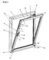
- FIG. 1 shows a window with a mounted on a frame 1 wings 2 and with a drive rod fitting 3 in a tilted position, in which the wing 1 is shown tilted about a horizontal tilting axis 4.
- the espagnolette fitting 3 is driven by a handle 5.
- the wing 2 can be rotated about a vertical axis of rotation 6 in a rotational position.
- the wing 2 can be locked in a closed position lying in the frame 1 and move in a gap ventilation position in which the plane of the wing 2 is a gap far away from the frame 1.
- the handle 5 has several positions, with Z being the closed position, with D the rotational position, with K the tilted position and L the gap ventilation position of the espagnolette fitting 3.
- the window has a corner bearing 8.
- the Ausstellschere 7 has a hinged on a pivot bearing 9 on the frame 1 outrigger 10, while the wing 2 has a tilting bearing 11 at its lower horizontal spar.
- the Espagnolette fitting 3 has one of the handle 5 drivable and in FIG. 2 shown drive rod 12.
- the drive rod 12 a plurality of locking pins 13 are driven.
- the locking pin 13 are opposite strike plates 14 which engage behind the locking pin 13 in the form-fitting positions provided.
- FIG. 2 shows greatly enlarged the located in tilting espagnolette fitting 3 in the area of the pivot bearing 9 of the Ausstellschere 7 FIG. 1
- a strike plate 15 is formed, which cooperates with a arranged on the drive rod 12 locking pin 16.
- the locking pin 16 In the gap ventilation position, the locking pin 16 is in the position marked L and penetrates into a pocket 18 of the striking plate 15 and connects the wing 2 with the Rotary bearing 9.
- the locking pin 16 also has at its free end a radial widening 19, with which it engages behind an edge 20 of the striking plate 15 of the pivot bearing 9 in the night ventilation position L.
- the strike plate 15 of the pivot bearing 9 has a further pocket 21 for receiving the locking pin 16 in the closed position Z and rotational position D.
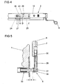
- FIG. 3 shows in a sectional view through the espagnolette fitting 3 from FIG. 2 in that the pocket 18 has a guide edge 22 for the locking pin 16 in order to receive the locking pin 16 in the slit-venting position L.
- the leading edge 22 points from the plane of the Locking pin 16 in the closed position Z to the plane of the locking pin 16 in the night ventilation position L.
- FIG. 4 shows in a view from position IV on the espagnolette fitting 3 from FIG. 2 in that a striking plate 23 arranged on the extension arm 10 of the deployment scissors 7 has two pockets 24, 25 which engage behind a further locking pin 26 in the slit-venting position L, rotational position D and closed position Z in a form-fitting manner.
- the striking plate 23 In the tilting position K shown, the striking plate 23 has a recess 27 for moving out the locking pin 26.
- the planes of the pockets 24, 25 are transverse to each other to the direction of movement of in FIG. 2 shown drive rod 12 offset and connected via a leading edge 28, so that in FIG. 1 represented wing 2 in the gap ventilation position L has a distance from the frame 1 and in the closed position Z is tight in the frame 1.
- FIG. 5 shows the corner bearing 8 FIG. 1 in a sectional view along the line V - V.
- the corner bearing 8 has on the axis of rotation 6 a pivot pin 29 on which a fixed to the wing 2 sleeve 30 is rotatably mounted. Furthermore, the corner bearing 8 has a direction perpendicular to the plane axis 31, which is a tilting of the wing 2 to the in FIG. 1 illustrated tilting axis 4 allows.
- a support 31 which supports the axis 31 is held in a longitudinal guide 33 of the frame 1.
- the longitudinal guide 33 allows movement of the wing 2 away from the frame 1 by the distance a in the gap ventilation position. This distance a preferably corresponds at least to the offset of the pockets 18, 21, 24, 25 of the striking plates 15, 23 from the Figures 3 and 4 ,
Landscapes
- Engineering & Computer Science (AREA)
- Mechanical Engineering (AREA)
- Specific Sealing Or Ventilating Devices For Doors And Windows (AREA)
- Air-Flow Control Members (AREA)
- Polysaccharides And Polysaccharide Derivatives (AREA)
- Portable Nailing Machines And Staplers (AREA)
- Hinges (AREA)
Description
- Die Erfindung betrifft einen Treibstangenbeschlag zur Verriegelung eines in einem Rahmen liegenden Flügels eines Fensters, einer Fenstertür oder dergleichen mit einer angetriebenen, an dem Flügel oder dem Blendrahmen anzuordnenden Treibstange, mit auf der Treibstange angeordneten Schließzapfen, mit den Schließzapfen gegenüberstehend anzuordnenden Schließblechen, und mit einer Spaltlüftungsstellung, in der die Schließzapfen gegenüber ihrer Lage in einer Schließstellung quer zur Bewegungsrichtung der Treibstange versetzt in dem Schließblech angeordnet sind und der Flügel im montierten Zustand einen Abstand zu dem Rahmen hat und mit einem Ausstellarm einer Ausstellschere für eine Kippstellung und eine Drehstellung des Flügels, wobei zumindest einer der Schließbleche eine Tasche zur Aufnahme des Schließzapfens in der Spaltlüftungsstellung aufweist.
- Ein solcher Treibstangenbeschlag ist beispielsweise aus der
EP 0 051 309 A2 bekannt. Bei diesem Treibstangenbeschlag ist der Flügel gegen ein vollständiges Schließen und weitergehendes Öffnen sicherbar. - Ein Treibstangenbeschlag ist weiterhin aus der
DE 1 259 222 A bekannt. Das Schließblech des Treibstangenbeschlages weist eine von einer Ausnehmung zu der Tasche geführte Nut auf, in der sich der auf einem Steuerarm angeordnete Schließzapfen bewegen lässt. Der Steuerarm wird über eine Steuernut von auf der Treibstange angetriebenen Steuerzapfen längsverschieblich geführt und in der Spaltlüftungsstellung verschwenkt. Damit wird in der Spaltlüftungsstellung der Flügel von dem Rahmen weggedrückt. Der Schließzapfen ist dabei in dem Schließblech gehalten. In der Schließstellung befindet sich der Schließzapfen beispielsweise mitten innerhalb der Nut. Nachteilig bei dem bekannten Treibstangenbeschlag ist jedoch, dass im Bereich von Scharnieren einer Drehachse des Flügels der Treibstangenbeschlag einfach aufgehebelt werden kann. Der bekannte Treibstangenbeschlag benötigt daher eine Vielzahl von weiteren Schließblechen und Schließzapfen zur Verriegelung des in Spaltlüftungsstellung befindlichen Flügels. - Weiterhin ist aus der
DE 30 43 925 C2 ein Treibstangenbeschlag bekannt, bei dem eine Steuerplatte an einem Scharnier angeordnet ist. Die Steuerplatte ist mit einer flügelseitigen Führungsplatte quer zur Bewegungsrichtung der Treibstange verbunden und hat eine Steuernut zur Steuerung der Bewegung des Flügels. Über die Steuernut lässt sich der Flügel in die Spaltlüftungsstellung bewegen. Nachteilig hierbei ist jedoch, dass dieser Treibstangenbeschlag keine Kippstellung des Flügels ermöglicht, da der Schließzapfen von dem Schließblech des Scharniers jederzeit hintergriffen wird. - Der Erfindung liegt das Problem zugrunde, einen Treibstangenbeschlag der eingangs genannten Art so weiterzubilden, dass er eine einfache Bewegung des Flügels von einer Schließstellung in eine Drehstellung, eine Kippstellung und eine Spaltlüftungsstellung ermöglicht und dass der Flügel in Spaltlüftungsstellung zuverlässig in dem Rahmen verriegelt ist.
- Dieses Problem wird erfindungsgemäß dadurch gelöst, dass das die Tasche zur Aufnahme des Schließzapfens in der Spaltlüftungsstellung aufweisende Schließblech auf einem Drehlager des Ausstellarms der Ausstellschere angeordnet ist.
- Durch diese Gestaltung ermöglicht der erfindungsgemäße Treibstangenbeschlag die Bewegung des Flügels mittels der Ausstellschere wahlweise in die Kippstellung oder die Drehstellung. In der Spaltlüftungsstellung befindet sich einer der Schließzapfen in dem Schließblech des Drehlagers. Der erfindungsgemäße, in Spaltlüftungsstellung befindliche Treibstangenbeschlag weist damit in dem Bereich der Ausstellschere in Spaltlüftungsstellung eine besonders hohe Stabilität auf. Damit ist der Flügel in Spaltlüftungsstellung zuverlässig in dem Rahmen verriegelt. Einem möglichen Aufhebelversuch des Flügels wird dank der Erfindung ein besonders hoher Widerstand entgegengesetzt.
- Als materialsparende Ausgestaltung der Erfindung ist vorgesehen, dass das Schließblech unmittelbar in einem Bandlappen des Drehlagers ausgebildet ist. Damit wird vom Bandlappen gleichzeitig die Verbindung zwischen Drehlager und Flügel und das Schließblech realisiert.
- Eine ungehinderte Bewegung des Flügels in die Kippstellung oder die Drehstellung lässt sich gemäß einer anderen vorteilhaften Weiterbildung der Erfindung einfach sicherstellen, wenn die Tasche des auf dem Drehlager angeordneten Schließblechs in Richtung der Drehachse des Drehlagers offen ist. Hierdurch gelangt der Schließzapfen in der Drehstellung und der Kippstellung aus dem Schließblech heraus, wodurch der Formschluss zwischen dem Schließzapfen und dem Schließblech aufgehoben wird.
- Zur weiteren Erhöhung der Sicherheit des erfindungsgemäßen Treibstangenbeschlages gegen ein Aufhebeln des in Schließstellung befindlichen Flügels trägt es bei, wenn das auf dem Drehlager angeordnete Schließblech eine zweite Tasche zur Aufnahme des Schließzapfens in Schließstellung hat.
- Eine Bewegung des Flügels in die Spaltlüftungsstellung beim Antrieb des erfindungsgemäßen Treibstangenbeschlages in die Spaltlüftungsstellung erfordert einen besonders geringen konstruktiven Aufwand, wenn die Tasche eine Führungskante für den Schließzapfen hat und wenn die Führungskante von der Ebene der Schließzapfen in Schließstellung zu der Ebene der Schließzapfen in Spaltlüftungsstellung weist. Vorzugsweise ist an zumindest einer von dem Drehlager entfernten Stellung eine weitere Einrichtung zur Bewegung des Flügels in die Spaltlüftungsstellung vorgesehen.
- Zur weiteren Erhöhung der Sicherheit des erfindungsgemäßen Treibstangenbeschlages gegen einen Aufhebelversuch des in Spaltlüftungsstellung befindlichen Flügels trägt es bei, wenn der Schließzapfen an seinem freien Ende eine radiale Verbreiterung aufweist und das an dem Drehlager angeordnete Schließblech einen Rand zur Hintergreifung der radialen Verbreiterung hat.
- Die Ausstellschere vermag gemäß einer anderen vorteilhaften Weiterbildung der Erfindung in Spaltlüftungsstellung besonders hohe Kräfte abzustützen, wenn an dem Ausstellarm ein weiteres Schließblech angeordnet ist und wenn das weitere Schließblech eine Tasche zur Aufnahme eines Schließzapfens in der Spaltlüftungsstellung hat.
- Zur weiteren Vereinfachung der Bewegung des Flügels in die Spaltlüftungsstellung trägt es gemäß einer anderen vorteilhaften Weiterbildung der Erfindung bei, wenn die Tasche des an dem Ausstellarm angeordneten Schließblechs gegenüber einer Tasche zur Aufnahme des Schließzapfens in Schließstellung versetzt angeordnet ist und wenn zwischen den Taschen eine Führungskante angeordnet ist.
- Ein zuverlässiges Einstellen des erfindungsgemäßen Treibstangenbeschlages in die jeweils verriegelte Spaltlüftungsstellung und die Schließstellung lässt sich einfach erreichen, wenn die Spaltlüftungsstellung und die Schließstellung jeweils als Endanschlag der Treibstange ausgebildet sind. Hierdurch wird sichergestellt, dass in der Endstellung der Flügel zuverlässig mit dem Rahmen verriegelt ist. Zwischen den Endstellungen sind dann die Drehstellung und/oder die Kippstellung angeordnet. Weiterhin können hierdurch die Taschen zur Aufnahme der Schließzapfen in Schließstellung und Spaltlüftungsstellung den jeweiligen Schließzapfen an drei Seiten umgreifen, was zur weiteren Erhöhung der Sicherheit des erfindungsgemäßen Treibstangenbeschlages gegen einen Aufhebelversuch des Flügels beiträgt.
- Die Erfindung lässt zahlreiche Ausführungsformen zu. Zur weiteren Verdeutlichung ihres Grundprinzips ist eine davon in der Zeichnung dargestellt und wird nachfolgend beschrieben. Diese zeigt in
- Fig. 1
- ein Fenster in Kippstellung mit einem erfindungsgemäßen Treibstangenbeschlag,
- Fig. 2
- eine stark vergrößerte Darstellung des Treibstangenbeschlages im Bereich eines Drehlagers einer Ausstellschere,
- Fig. 3
- eine Schnittdarstellung durch den Treibstangenbeschlag aus
Figur 2 entlang der Linie III - III, - Fig. 4
- eine Ansicht von Position IV auf den Treibstangenbeschlag aus
Figur 2 , - Fig. 5
- eine Schnittdarstellung durch ein Ecklager des Treibstangenbeschlages aus
Figur 1 entlang der Linie V - V. -
Figur 1 zeigt ein Fenster mit einem an einem Rahmen 1 gelagerten Flügel 2 und mit einem Treibstangenbeschlag 3 in einer Kippstellung, bei der der Flügel 1 um eine horizontale Kippachse 4 gekippt dargestellt ist. Der Treibstangenbeschlag 3 ist von einer Handhabe 5 antreibbar. Der Flügel 2 lässt sich um eine vertikale Drehachse 6 in eine Drehstellung drehen. Weiterhin lässt sich der Flügel 2 in einer in dem Rahmen 1 liegenden Schließstellung verriegeln und in eine Spaltlüftungsstellung bewegen, in der die Ebene des Flügels 2 einen Spalt weit von dem Rahmen 1 entfernt ist. Hierfür hat die Handhabe 5 mehrere Stellungen, wobei mit Z die Schließstellung, mit D die Drehstellung, mit K die Kippstellung und mit L die Spaltlüftungsstellung des Treibstangenbeschlages 3 gekennzeichnet ist. - In der dargestellten Kippstellung wird der Flügel 2 von einer Ausstellschere 7 gehalten. Im Schnittpunkt der Achsen 4, 6 hat das Fenster ein Ecklager 8. Die Ausstellschere 7 hat einen über ein Drehlager 9 an dem Rahmen 1 angelenkten Ausstellarm 10, während der Flügel 2 an seinem unteren horizontalen Holm ein Kipplager 11 hat. Der Treibstangenbeschlag 3 hat eine von der Handhabe 5 antreibbare und in
Figur 2 dargestellte Treibstange 12. Über die Treibstange 12 sind mehrere Schließzapfen 13 antreibbar. Den Schließzapfen 13 stehen Schließbleche 14 gegenüber, welche die Schließzapfen 13 in vorgesehenen Stellungen formschlüssig hintergreifen. -
Figur 2 zeigt stark vergrößert den in Kippstellung befindlichen Treibstangenbeschlag 3 im Bereich des Drehlagers 9 der Ausstellschere 7 ausFigur 1 bei gegen den Rahmen 1 gedrücktem Flügel 2. Hierbei ist zu erkennen, dass an dem Drehlager 9 ein Schließblech 15 ausgebildet ist, welches mit einem auf der Treibstange 12 angeordneten Schließzapfen 16 zusammenwirkt. Das Schließblech 15 hat im Bereich der dargestellten Kippstellung K eine Ausnehmung 17 zur Durchführung des Schließzapfens 16. In der Spaltlüftungsstellung befindet sich der Schließzapfen 16 in der mit L gekennzeichneten Stellung und dringt in eine Tasche 18 des Schließblechs 15 ein und verbindet den Flügel 2 mit dem Drehlager 9. Der Schließzapfen 16 hat zudem an seinem freien Ende eine radiale Verbreiterung 19, mit der er einen Rand 20 des Schließblechs 15 des Drehlagers 9 in Spaltlüftungsstellung L hintergreift. Weiterhin ist inFigur 2 dargestellt, dass das Schließblech 15 des Drehlagers 9 eine weitere Tasche 21 zur Aufnahme des Schließzapfens 16 in der Schließstellung Z und Drehstellung D hat. -
Figur 3 zeigt in einer Schnittdarstellung durch den Treibstangenbeschlag 3 ausFigur 2 , dass die Tasche 18 zur Aufnahme des Schließzapfens 16 in Spaltlüftungsstellung L eine Führungskante 22 für den Schließzapfen 16 hat. Die Führungskante 22 weist von der Ebene des Schließzapfens 16 in Schließstellung Z zu der Ebene der Schließzapfen 16 in Spaltlüftungsstellung L hin. Damit wird bei der Bewegung des Treibstangenbeschlages 3 in die Spaltlüftungsstellung L der Flügel 2 von dem Rahmen 1 weggedrückt. -
Figur 4 zeigt in einer Ansicht von Position IV auf den Treibstangenbeschlag 3 ausFigur 2 , dass ein auf dem Ausstellarm 10 der Ausstellschere 7 angeordnetes Schließblech 23 zwei Taschen 24, 25 aufweist, welche einen weiteren Schließzapfen 26 in Spaltlüftungsstellung L, Drehstellung D und Schließstellung Z formschlüssig hintergreifen. In der dargestellten Kippstellung K hat das Schließblech 23 eine Ausnehmung 27 zur Herausbewegung des Schließzapfens 26. Die Ebenen der Taschen 24, 25 sind quer zueinander zur Bewegungsrichtung der inFigur 2 dargestellten Treibstange 12 versetzt und über eine Führungskante 28 verbunden, so dass der inFigur 1 dargestellte Flügel 2 in der Spaltlüftungsstellung L einen Abstand zu dem Rahmen 1 hat und in der Schließstellung Z dicht in dem Rahmen 1 liegt. -
Figur 5 zeigt das Ecklager 8 ausFigur 1 in einer Schnittdarstellung entlang der Linie V - V. Das Ecklager 8 hat auf der Drehachse 6 einen Drehbolzen 29, auf dem eine an dem Flügel 2 befestigte Hülse 30 drehbar gelagert ist. Weiterhin hat das Ecklager 8 eine senkrecht zur Zeichenebene weisende Achse 31, welche ein Kippen des Flügels 2 um die inFigur 1 dargestellte Kippachse 4 ermöglicht. Ein die Achse 31 abstützender Haltebock 32 wird in einer Längsführung 33 des Rahmens 1 gehalten. Die Längsführung 33 ermöglicht eine Bewegung des Flügels 2 von dem Rahmen 1 weg um den Abstand a in der Spaltlüftungsstellung. Dieser Abstand a entspricht vorzugsweise mindestens dem Versatz der Taschen 18, 21, 24, 25 der Schließbleche 15, 23 aus denFiguren 3 und4 .
Claims (9)
- Treibstangenbeschlag (3) zur Verriegelung eines in einem Rahmen (1) liegenden Flügels (2) eines Fensters, einer Fenstertür oder dergleichen mit einer angetriebenen, an dem Flügel (2) oder dem Blendrahmen anzuordnenden Treibstange (12), mit auf der Treibstange (12) angeordneten Schließzapfen (16,26), mit den Schließzapfen (16,26) gegenüberstehend anzuordnenden Schließblechen (15,23) und mit einer Spaltlüftungsstellung (L), in der die Schließzapfen (16,26) gegenüber ihrer Lage in einer Schließstellung quer zur Bewegungsrichtung der Treibstange (12) versetzt in dem Schließblech (15,23) angeordnet sind und der Flügel (2) im montierten Zustand einen Abstand zu dem Rahmen (1) hat und mit einem Ausstellarm (10) einer Ausstellschere (7) für eine Kippstellung (K) und eine Drehstellung (D) des Flügels (2), wobei zumindest eines der Schließbleche (15,23) eine Tasche (18,24) zur Aufnahme des Schließzapfens (16,26) in der Spaltlüftungsstellung (L) aufweist, dadurch gekennzeichnet, dass das die Tasche (18) zur Aufnahme des Schließzapfens (16) in der Spaltlüftungsstellung (L) aufweisende Schließblech (15) auf einem Drehlager (9) des Ausstellarms (10) der Ausstellschere (7) angeordnet ist.
- Treibstangenbeschlag nach Anspruch 1, dadurch gekennzeichnet, dass das Schließblech (15) unmittelbar in einem Bandlappen (9a) des Drehlagers (9) ausgebildet ist.
- Treibstangenbeschlag nach Anspruch 1 oder 2, dadurch gekennzeichnet, dass die Tasche (18) des auf dem Drehlager (9) angeordneten Schließblechs (15) in Richtung der Drehachse (6) des Drehlagers (9) offen ist.
- Treibstangenbeschlag nach einem der Ansprüche 1 bis 3, dadurch gekennzeichnet, dass das auf dem Drehlager (9) angeordnete Schließblech (15) eine zweite Tasche (21) zur Aufnahme des Schließzapfens (16) in Schließstellung (Z) hat.
- Treibstangenbeschlag nach zumindest einem der vorhergehenden Ansprüche, dadurch gekennzeichnet, dass die Tasche (18) eine Führungskante (22) für den Schließzapfen (16) hat und dass die Führungskante (22) von der Ebene der Schließzapfen (16) in Schließstellung (Z) zu der Ebene der Schließzapfen (16) in Spaltlüftungsstellung (L) weist.
- Treibstangenbeschlag nach zumindest einem der vorhergehenden Ansprüche, dadurch gekennzeichnet, dass der Schließzapfen (16) an seinem freien Ende eine radiale Verbreiterung (19) aufweist und das an dem Drehlager (9) angeordnete Schließblech (15) einen Rand (20) zur Hintergreifung der radialen Verbreiterung (19) hat.
- Treibstangenbeschlag nach zumindest einem der vorhergehenden Ansprüche, dadurch gekennzeichnet, dass an dem Ausstellarm (10) ein weiteres Schließblech (23) angeordnet ist und dass das weitere Schließblech (23) eine Tasche (24) zur Aufnahme eines Schließzapfens (26) in der Spaltlüftungsstellung (L) hat.
- Treibstangenbeschlag nach Anspruch 7, dadurch gekennzeichnet, dass die Tasche (24) des an dem Ausstellarm (10) angeordneten Schließblechs (23) gegenüber einer Tasche (25) zur Aufnahme des Schließzapfens (26) in Schließstellung versetzt angeordnet ist und dass zwischen den Taschen (24, 25) eine Führungskante (28) angeordnet ist.
- Treibstangenbeschlag nach zumindest einem der vorhergehenden Ansprüche, dadurch gekennzeichnet, dass die Spaltlüftungsstellung (L) und die Schließstellung (Z) jeweils als Endanschlag der Treibstange (12) ausgebildet sind.
Applications Claiming Priority (2)
| Application Number | Priority Date | Filing Date | Title |
|---|---|---|---|
| DE102004014508A DE102004014508A1 (de) | 2004-03-25 | 2004-03-25 | Treibstangenbeschlag |
| DE102004014508 | 2004-03-25 |
Publications (3)
| Publication Number | Publication Date |
|---|---|
| EP1580381A2 EP1580381A2 (de) | 2005-09-28 |
| EP1580381A3 EP1580381A3 (de) | 2009-04-01 |
| EP1580381B1 true EP1580381B1 (de) | 2010-06-02 |
Family
ID=34854033
Family Applications (1)
| Application Number | Title | Priority Date | Filing Date |
|---|---|---|---|
| EP05101648A Expired - Lifetime EP1580381B1 (de) | 2004-03-25 | 2005-03-03 | Treibstangenbeschlag |
Country Status (3)
| Country | Link |
|---|---|
| EP (1) | EP1580381B1 (de) |
| AT (1) | ATE470040T1 (de) |
| DE (2) | DE102004014508A1 (de) |
Families Citing this family (6)
| Publication number | Priority date | Publication date | Assignee | Title |
|---|---|---|---|---|
| ITBO20050695A1 (it) * | 2005-11-15 | 2007-05-16 | Gsg Int Spa | Serramento con apertura ad anta |
| DE102010022547A1 (de) * | 2010-06-02 | 2011-12-08 | Roto Frank Ag | Fenster oder dergleichen mit einem Beschlag, Beschlag, Verfahren zum Offenfeststellen eines Fensters oder dergleichen sowie Anwendung des Verfahrens bei einem Fenster oder dergleichen |
| DE102011001679A1 (de) * | 2011-03-30 | 2012-10-04 | Hautau Gmbh | Schliessplatte für einen von einem Blendrahmen abstellbaren Fenster-oder Türflügel |
| DE102013222100A1 (de) * | 2013-10-30 | 2015-04-30 | Maco Technologie Gmbh | Schließteil |
| CN104373024B (zh) * | 2014-11-13 | 2016-06-15 | 广东坚朗五金制品股份有限公司 | 门窗微通风结构 |
| DE102022201672A1 (de) | 2022-02-17 | 2023-08-17 | Aug. Winkhaus Gmbh & Co. Kg | Treibstangenbeschlag und Fenster, Fenstertür oder dgl. mit rahmenartig zusammengesetzten Holmen und mit einem solchen Treibstangenbeschlag |
Family Cites Families (5)
| Publication number | Priority date | Publication date | Assignee | Title |
|---|---|---|---|---|
| DE1259222B (de) * | 1964-01-18 | 1968-01-18 | Jaeger Frank K G | Betaetigungsvorrichtung zum OEffnen und Schliessen eines um eine waagerechte Achse kippbaren oder klappbaren Fluegels, insbesondere von Kipp-Schwenkfluegelfenstern, -tueren od. dgl. |
| EP0051309B2 (de) * | 1980-11-03 | 2000-12-06 | Aug. Winkhaus GmbH & Co. KG | Fenster |
| DE3043925C2 (de) * | 1980-11-03 | 1994-09-29 | Winkhaus Fa August | Vorrichtung an einem Fenster zur Einstellung des Flügelrahmens in eine Spaltöffnungsstellung |
| DE19825071C2 (de) * | 1998-06-04 | 2002-06-27 | Esco Metallbaubeschlag Handel Gmbh | Parallelausstellfenster mit Drehfunktion |
| DE10162659A1 (de) * | 2001-12-20 | 2003-07-03 | Winkhaus Fa August | Drehkippfenster |
-
2004
- 2004-03-25 DE DE102004014508A patent/DE102004014508A1/de not_active Withdrawn
-
2005
- 2005-03-03 AT AT05101648T patent/ATE470040T1/de active
- 2005-03-03 DE DE502005009663T patent/DE502005009663D1/de not_active Expired - Lifetime
- 2005-03-03 EP EP05101648A patent/EP1580381B1/de not_active Expired - Lifetime
Also Published As
| Publication number | Publication date |
|---|---|
| DE102004014508A1 (de) | 2005-12-15 |
| ATE470040T1 (de) | 2010-06-15 |
| EP1580381A3 (de) | 2009-04-01 |
| DE502005009663D1 (de) | 2010-07-15 |
| EP1580381A2 (de) | 2005-09-28 |
Similar Documents
| Publication | Publication Date | Title |
|---|---|---|
| EP1836367B1 (de) | Dreh-/kippfenster mit elektromotorischem antrieb mit schubkette | |
| AT507862B1 (de) | Vorrichtung für das steuern der schliessfolge von zweiflügeligen schwenktüren | |
| EP1312742A2 (de) | Austellvorrichtung für einen Kipp-Flügel, insbesondere Dreh-Kipp-Flügel eines Fensters, einer Tür oder dergleichen, entsprechende Fenstereinrichtung und entsprechendes Verfahren zum motorischen und manuellen Kippen | |
| EP1580381B1 (de) | Treibstangenbeschlag | |
| DE3022163A1 (de) | Dreh-kipp-beschlag fuer fenster, tueren o.dgl. mit spaltlueftung | |
| EP0570945A1 (de) | Verdeckt eingebautes Scharniergelenk | |
| EP0096744A2 (de) | Drehkippbeschlag | |
| EP2149661B1 (de) | Gebäudeabschluss in sprengwirkungshemmender und/oder einbruchhemmender Ausführung | |
| EP3183408B1 (de) | Steuerelement für eine beschlaganordnung | |
| EP0531626B1 (de) | Beschlag für insb. zwangsweise kipp- und parallel abstellbare Flügel | |
| DE3617216C2 (de) | ||
| EP1147278B1 (de) | Verschlussvorrichtung für den unterschlagenden flügel zweiflügeliger setzholzloser fenster, türen od. dgl. | |
| EP3237708B1 (de) | Beschlag zum einbau zwischen einem flügel und einem festen rahmen eines fensters, einer tür oder dergleichen sowie fenster, tür oder dergleichen mit einem derartigen beschlag | |
| DE19906071C2 (de) | Drehbegrenzer für Dreh-Schiebe-Fenster | |
| DE3111579A1 (de) | Drehkippfenster | |
| DE102008028598A1 (de) | Insektenschutztür | |
| DE2729394A1 (de) | Verriegelungseinrichtung fuer fenster, tueren o.dgl. | |
| DE102004014509A1 (de) | Treibstangenbeschlag | |
| EP1715125A2 (de) | Drehkipp- bzw. Kippdrehfensterbeschlag mit Spaltlüftungsstellung | |
| EP1267026B1 (de) | Beschlag für ein Fenster, eine Tür oder dergleichen umfassend einen Beschlagarm, eine Treibstange und eine Spaltlüftvorrichtung sowie Fenster, Tür oder dergleichen mit einem solchen Beschlag | |
| EP1780362B1 (de) | Motorischer Antrieb für schwenkbaren Flügel | |
| EP2899341B1 (de) | Beschlaganordnung | |
| DE3939043A1 (de) | Treibstangenbeschlag fuer fenster, tueren oder dergleichen | |
| DE3905995C2 (de) | ||
| DE1962906C3 (de) | Beschlag fur Dreh-Kipp- oder Dreh-Klappfenster |
Legal Events
| Date | Code | Title | Description |
|---|---|---|---|
| PUAI | Public reference made under article 153(3) epc to a published international application that has entered the european phase |
Free format text: ORIGINAL CODE: 0009012 |
|
| AK | Designated contracting states |
Kind code of ref document: A2 Designated state(s): AT BE BG CH CY CZ DE DK EE ES FI FR GB GR HU IE IS IT LI LT LU MC NL PL PT RO SE SI SK TR |
|
| AX | Request for extension of the european patent |
Extension state: AL BA HR LV MK YU |
|
| PUAL | Search report despatched |
Free format text: ORIGINAL CODE: 0009013 |
|
| AK | Designated contracting states |
Kind code of ref document: A3 Designated state(s): AT BE BG CH CY CZ DE DK EE ES FI FR GB GR HU IE IS IT LI LT LU MC NL PL PT RO SE SI SK TR |
|
| AX | Request for extension of the european patent |
Extension state: AL BA HR LV MK YU |
|
| 17P | Request for examination filed |
Effective date: 20090827 |
|
| 17Q | First examination report despatched |
Effective date: 20091028 |
|
| AKX | Designation fees paid |
Designated state(s): AT BE BG CH CY CZ DE DK EE ES FI FR GB GR HU IE IS IT LI LT LU MC NL PL PT RO SE SI SK TR |
|
| GRAP | Despatch of communication of intention to grant a patent |
Free format text: ORIGINAL CODE: EPIDOSNIGR1 |
|
| GRAS | Grant fee paid |
Free format text: ORIGINAL CODE: EPIDOSNIGR3 |
|
| GRAA | (expected) grant |
Free format text: ORIGINAL CODE: 0009210 |
|
| AK | Designated contracting states |
Kind code of ref document: B1 Designated state(s): AT BE BG CH CY CZ DE DK EE ES FI FR GB GR HU IE IS IT LI LT LU MC NL PL PT RO SE SI SK TR |
|
| REG | Reference to a national code |
Ref country code: GB Ref legal event code: FG4D Free format text: NOT ENGLISH |
|
| REG | Reference to a national code |
Ref country code: CH Ref legal event code: EP |
|
| REG | Reference to a national code |
Ref country code: IE Ref legal event code: FG4D Free format text: LANGUAGE OF EP DOCUMENT: GERMAN |
|
| REF | Corresponds to: |
Ref document number: 502005009663 Country of ref document: DE Date of ref document: 20100715 Kind code of ref document: P |
|
| REG | Reference to a national code |
Ref country code: NL Ref legal event code: VDEP Effective date: 20100602 |
|
| PG25 | Lapsed in a contracting state [announced via postgrant information from national office to epo] |
Ref country code: LT Free format text: LAPSE BECAUSE OF FAILURE TO SUBMIT A TRANSLATION OF THE DESCRIPTION OR TO PAY THE FEE WITHIN THE PRESCRIBED TIME-LIMIT Effective date: 20100602 Ref country code: SE Free format text: LAPSE BECAUSE OF FAILURE TO SUBMIT A TRANSLATION OF THE DESCRIPTION OR TO PAY THE FEE WITHIN THE PRESCRIBED TIME-LIMIT Effective date: 20100602 |
|
| LTIE | Lt: invalidation of european patent or patent extension |
Effective date: 20100602 |
|
| PG25 | Lapsed in a contracting state [announced via postgrant information from national office to epo] |
Ref country code: SI Free format text: LAPSE BECAUSE OF FAILURE TO SUBMIT A TRANSLATION OF THE DESCRIPTION OR TO PAY THE FEE WITHIN THE PRESCRIBED TIME-LIMIT Effective date: 20100602 Ref country code: FI Free format text: LAPSE BECAUSE OF FAILURE TO SUBMIT A TRANSLATION OF THE DESCRIPTION OR TO PAY THE FEE WITHIN THE PRESCRIBED TIME-LIMIT Effective date: 20100602 |
|
| PG25 | Lapsed in a contracting state [announced via postgrant information from national office to epo] |
Ref country code: PL Free format text: LAPSE BECAUSE OF FAILURE TO SUBMIT A TRANSLATION OF THE DESCRIPTION OR TO PAY THE FEE WITHIN THE PRESCRIBED TIME-LIMIT Effective date: 20100602 Ref country code: GR Free format text: LAPSE BECAUSE OF FAILURE TO SUBMIT A TRANSLATION OF THE DESCRIPTION OR TO PAY THE FEE WITHIN THE PRESCRIBED TIME-LIMIT Effective date: 20100903 Ref country code: CY Free format text: LAPSE BECAUSE OF FAILURE TO SUBMIT A TRANSLATION OF THE DESCRIPTION OR TO PAY THE FEE WITHIN THE PRESCRIBED TIME-LIMIT Effective date: 20100602 |
|
| REG | Reference to a national code |
Ref country code: IE Ref legal event code: FD4D |
|
| PG25 | Lapsed in a contracting state [announced via postgrant information from national office to epo] |
Ref country code: NL Free format text: LAPSE BECAUSE OF FAILURE TO SUBMIT A TRANSLATION OF THE DESCRIPTION OR TO PAY THE FEE WITHIN THE PRESCRIBED TIME-LIMIT Effective date: 20100602 Ref country code: IE Free format text: LAPSE BECAUSE OF FAILURE TO SUBMIT A TRANSLATION OF THE DESCRIPTION OR TO PAY THE FEE WITHIN THE PRESCRIBED TIME-LIMIT Effective date: 20100602 Ref country code: EE Free format text: LAPSE BECAUSE OF FAILURE TO SUBMIT A TRANSLATION OF THE DESCRIPTION OR TO PAY THE FEE WITHIN THE PRESCRIBED TIME-LIMIT Effective date: 20100602 |
|
| PG25 | Lapsed in a contracting state [announced via postgrant information from national office to epo] |
Ref country code: CZ Free format text: LAPSE BECAUSE OF FAILURE TO SUBMIT A TRANSLATION OF THE DESCRIPTION OR TO PAY THE FEE WITHIN THE PRESCRIBED TIME-LIMIT Effective date: 20100602 Ref country code: SK Free format text: LAPSE BECAUSE OF FAILURE TO SUBMIT A TRANSLATION OF THE DESCRIPTION OR TO PAY THE FEE WITHIN THE PRESCRIBED TIME-LIMIT Effective date: 20100602 Ref country code: RO Free format text: LAPSE BECAUSE OF FAILURE TO SUBMIT A TRANSLATION OF THE DESCRIPTION OR TO PAY THE FEE WITHIN THE PRESCRIBED TIME-LIMIT Effective date: 20100602 Ref country code: PT Free format text: LAPSE BECAUSE OF FAILURE TO SUBMIT A TRANSLATION OF THE DESCRIPTION OR TO PAY THE FEE WITHIN THE PRESCRIBED TIME-LIMIT Effective date: 20101004 Ref country code: IS Free format text: LAPSE BECAUSE OF FAILURE TO SUBMIT A TRANSLATION OF THE DESCRIPTION OR TO PAY THE FEE WITHIN THE PRESCRIBED TIME-LIMIT Effective date: 20101002 |
|
| PG25 | Lapsed in a contracting state [announced via postgrant information from national office to epo] |
Ref country code: IT Free format text: LAPSE BECAUSE OF FAILURE TO SUBMIT A TRANSLATION OF THE DESCRIPTION OR TO PAY THE FEE WITHIN THE PRESCRIBED TIME-LIMIT Effective date: 20100602 |
|
| PLBE | No opposition filed within time limit |
Free format text: ORIGINAL CODE: 0009261 |
|
| STAA | Information on the status of an ep patent application or granted ep patent |
Free format text: STATUS: NO OPPOSITION FILED WITHIN TIME LIMIT |
|
| PG25 | Lapsed in a contracting state [announced via postgrant information from national office to epo] |
Ref country code: DK Free format text: LAPSE BECAUSE OF FAILURE TO SUBMIT A TRANSLATION OF THE DESCRIPTION OR TO PAY THE FEE WITHIN THE PRESCRIBED TIME-LIMIT Effective date: 20100602 |
|
| 26N | No opposition filed |
Effective date: 20110303 |
|
| PGFP | Annual fee paid to national office [announced via postgrant information from national office to epo] |
Ref country code: FR Payment date: 20110401 Year of fee payment: 7 |
|
| REG | Reference to a national code |
Ref country code: DE Ref legal event code: R097 Ref document number: 502005009663 Country of ref document: DE Effective date: 20110302 |
|
| BERE | Be: lapsed |
Owner name: AUG. WINKHAUS G.M.B.H. & CO. KG Effective date: 20110331 |
|
| PG25 | Lapsed in a contracting state [announced via postgrant information from national office to epo] |
Ref country code: MC Free format text: LAPSE BECAUSE OF NON-PAYMENT OF DUE FEES Effective date: 20110331 |
|
| REG | Reference to a national code |
Ref country code: CH Ref legal event code: PL |
|
| GBPC | Gb: european patent ceased through non-payment of renewal fee |
Effective date: 20110303 |
|
| PG25 | Lapsed in a contracting state [announced via postgrant information from national office to epo] |
Ref country code: BE Free format text: LAPSE BECAUSE OF NON-PAYMENT OF DUE FEES Effective date: 20110331 |
|
| PG25 | Lapsed in a contracting state [announced via postgrant information from national office to epo] |
Ref country code: CH Free format text: LAPSE BECAUSE OF NON-PAYMENT OF DUE FEES Effective date: 20110331 Ref country code: LI Free format text: LAPSE BECAUSE OF NON-PAYMENT OF DUE FEES Effective date: 20110331 |
|
| PG25 | Lapsed in a contracting state [announced via postgrant information from national office to epo] |
Ref country code: GB Free format text: LAPSE BECAUSE OF NON-PAYMENT OF DUE FEES Effective date: 20110303 |
|
| PGFP | Annual fee paid to national office [announced via postgrant information from national office to epo] |
Ref country code: DE Payment date: 20120411 Year of fee payment: 8 |
|
| REG | Reference to a national code |
Ref country code: FR Ref legal event code: ST Effective date: 20121130 |
|
| PG25 | Lapsed in a contracting state [announced via postgrant information from national office to epo] |
Ref country code: FR Free format text: LAPSE BECAUSE OF NON-PAYMENT OF DUE FEES Effective date: 20120402 |
|
| PGFP | Annual fee paid to national office [announced via postgrant information from national office to epo] |
Ref country code: AT Payment date: 20120330 Year of fee payment: 8 |
|
| PG25 | Lapsed in a contracting state [announced via postgrant information from national office to epo] |
Ref country code: LU Free format text: LAPSE BECAUSE OF NON-PAYMENT OF DUE FEES Effective date: 20110303 |
|
| PG25 | Lapsed in a contracting state [announced via postgrant information from national office to epo] |
Ref country code: BG Free format text: LAPSE BECAUSE OF FAILURE TO SUBMIT A TRANSLATION OF THE DESCRIPTION OR TO PAY THE FEE WITHIN THE PRESCRIBED TIME-LIMIT Effective date: 20100902 Ref country code: TR Free format text: LAPSE BECAUSE OF FAILURE TO SUBMIT A TRANSLATION OF THE DESCRIPTION OR TO PAY THE FEE WITHIN THE PRESCRIBED TIME-LIMIT Effective date: 20100602 |
|
| PG25 | Lapsed in a contracting state [announced via postgrant information from national office to epo] |
Ref country code: HU Free format text: LAPSE BECAUSE OF FAILURE TO SUBMIT A TRANSLATION OF THE DESCRIPTION OR TO PAY THE FEE WITHIN THE PRESCRIBED TIME-LIMIT Effective date: 20100602 Ref country code: ES Free format text: LAPSE BECAUSE OF FAILURE TO SUBMIT A TRANSLATION OF THE DESCRIPTION OR TO PAY THE FEE WITHIN THE PRESCRIBED TIME-LIMIT Effective date: 20100913 |
|
| REG | Reference to a national code |
Ref country code: AT Ref legal event code: MM01 Ref document number: 470040 Country of ref document: AT Kind code of ref document: T Effective date: 20130303 |
|
| REG | Reference to a national code |
Ref country code: DE Ref legal event code: R119 Ref document number: 502005009663 Country of ref document: DE Effective date: 20131001 |
|
| PG25 | Lapsed in a contracting state [announced via postgrant information from national office to epo] |
Ref country code: AT Free format text: LAPSE BECAUSE OF NON-PAYMENT OF DUE FEES Effective date: 20130303 Ref country code: DE Free format text: LAPSE BECAUSE OF NON-PAYMENT OF DUE FEES Effective date: 20131001 |