EP1580381A2 - Treibstangenbeschlag - Google Patents
Treibstangenbeschlag Download PDFInfo
- Publication number
- EP1580381A2 EP1580381A2 EP05101648A EP05101648A EP1580381A2 EP 1580381 A2 EP1580381 A2 EP 1580381A2 EP 05101648 A EP05101648 A EP 05101648A EP 05101648 A EP05101648 A EP 05101648A EP 1580381 A2 EP1580381 A2 EP 1580381A2
- Authority
- EP
- European Patent Office
- Prior art keywords
- locking pin
- wing
- espagnolette fitting
- fitting according
- Prior art date
- Legal status (The legal status is an assumption and is not a legal conclusion. Google has not performed a legal analysis and makes no representation as to the accuracy of the status listed.)
- Granted
Links
- 238000009423 ventilation Methods 0.000 claims description 38
Images


Classifications
-
- E—FIXED CONSTRUCTIONS
- E05—LOCKS; KEYS; WINDOW OR DOOR FITTINGS; SAFES
- E05C—BOLTS OR FASTENING DEVICES FOR WINGS, SPECIALLY FOR DOORS OR WINDOWS
- E05C17/00—Devices for holding wings open; Devices for limiting opening of wings or for holding wings open by a movable member extending between frame and wing; Braking devices, stops or buffers, combined therewith
-
- E—FIXED CONSTRUCTIONS
- E05—LOCKS; KEYS; WINDOW OR DOOR FITTINGS; SAFES
- E05C—BOLTS OR FASTENING DEVICES FOR WINGS, SPECIALLY FOR DOORS OR WINDOWS
- E05C9/00—Arrangements of simultaneously actuated bolts or other securing devices at well-separated positions on the same wing
- E05C9/18—Details of fastening means or of fixed retaining means for the ends of bars
- E05C9/1808—Keepers
-
- E—FIXED CONSTRUCTIONS
- E05—LOCKS; KEYS; WINDOW OR DOOR FITTINGS; SAFES
- E05C—BOLTS OR FASTENING DEVICES FOR WINGS, SPECIALLY FOR DOORS OR WINDOWS
- E05C9/00—Arrangements of simultaneously actuated bolts or other securing devices at well-separated positions on the same wing
- E05C9/18—Details of fastening means or of fixed retaining means for the ends of bars
- E05C9/1825—Fastening means
- E05C9/1833—Fastening means performing sliding movements
- E05C9/185—Fastening means performing sliding movements parallel with actuating bar
-
- E—FIXED CONSTRUCTIONS
- E05—LOCKS; KEYS; WINDOW OR DOOR FITTINGS; SAFES
- E05D—HINGES OR SUSPENSION DEVICES FOR DOORS, WINDOWS OR WINGS
- E05D15/00—Suspension arrangements for wings
- E05D15/48—Suspension arrangements for wings allowing alternative movements
- E05D15/52—Suspension arrangements for wings allowing alternative movements for opening about a vertical as well as a horizontal axis
- E05D15/5214—Corner supports
-
- E—FIXED CONSTRUCTIONS
- E05—LOCKS; KEYS; WINDOW OR DOOR FITTINGS; SAFES
- E05D—HINGES OR SUSPENSION DEVICES FOR DOORS, WINDOWS OR WINGS
- E05D3/00—Hinges with pins
- E05D3/02—Hinges with pins with one pin
- E05D3/022—Hinges with pins with one pin allowing an additional lateral movement, e.g. for sealing
-
- E—FIXED CONSTRUCTIONS
- E05—LOCKS; KEYS; WINDOW OR DOOR FITTINGS; SAFES
- E05C—BOLTS OR FASTENING DEVICES FOR WINGS, SPECIALLY FOR DOORS OR WINDOWS
- E05C17/00—Devices for holding wings open; Devices for limiting opening of wings or for holding wings open by a movable member extending between frame and wing; Braking devices, stops or buffers, combined therewith
- E05C17/02—Devices for holding wings open; Devices for limiting opening of wings or for holding wings open by a movable member extending between frame and wing; Braking devices, stops or buffers, combined therewith by mechanical means
- E05C17/04—Devices for holding wings open; Devices for limiting opening of wings or for holding wings open by a movable member extending between frame and wing; Braking devices, stops or buffers, combined therewith by mechanical means with a movable bar or equivalent member extending between frame and wing
- E05C17/12—Devices for holding wings open; Devices for limiting opening of wings or for holding wings open by a movable member extending between frame and wing; Braking devices, stops or buffers, combined therewith by mechanical means with a movable bar or equivalent member extending between frame and wing consisting of a single rod
- E05C17/24—Devices for holding wings open; Devices for limiting opening of wings or for holding wings open by a movable member extending between frame and wing; Braking devices, stops or buffers, combined therewith by mechanical means with a movable bar or equivalent member extending between frame and wing consisting of a single rod pivoted at one end, and with the other end running along a guide member
-
- E—FIXED CONSTRUCTIONS
- E05—LOCKS; KEYS; WINDOW OR DOOR FITTINGS; SAFES
- E05C—BOLTS OR FASTENING DEVICES FOR WINGS, SPECIALLY FOR DOORS OR WINDOWS
- E05C17/00—Devices for holding wings open; Devices for limiting opening of wings or for holding wings open by a movable member extending between frame and wing; Braking devices, stops or buffers, combined therewith
- E05C17/02—Devices for holding wings open; Devices for limiting opening of wings or for holding wings open by a movable member extending between frame and wing; Braking devices, stops or buffers, combined therewith by mechanical means
- E05C17/46—Devices for holding wings open; Devices for limiting opening of wings or for holding wings open by a movable member extending between frame and wing; Braking devices, stops or buffers, combined therewith by mechanical means in which the wing or a member fixed thereon is engaged by a movable fastening member in a fixed position; in which a movable fastening member mounted on the wing engages a stationary member
- E05C17/48—Devices for holding wings open; Devices for limiting opening of wings or for holding wings open by a movable member extending between frame and wing; Braking devices, stops or buffers, combined therewith by mechanical means in which the wing or a member fixed thereon is engaged by a movable fastening member in a fixed position; in which a movable fastening member mounted on the wing engages a stationary member comprising a sliding securing member
-
- E—FIXED CONSTRUCTIONS
- E05—LOCKS; KEYS; WINDOW OR DOOR FITTINGS; SAFES
- E05D—HINGES OR SUSPENSION DEVICES FOR DOORS, WINDOWS OR WINGS
- E05D15/00—Suspension arrangements for wings
- E05D15/48—Suspension arrangements for wings allowing alternative movements
- E05D15/52—Suspension arrangements for wings allowing alternative movements for opening about a vertical as well as a horizontal axis
- E05D15/5205—Suspension arrangements for wings allowing alternative movements for opening about a vertical as well as a horizontal axis with horizontally-extending checks
-
- E—FIXED CONSTRUCTIONS
- E05—LOCKS; KEYS; WINDOW OR DOOR FITTINGS; SAFES
- E05Y—INDEXING SCHEME ASSOCIATED WITH SUBCLASSES E05D AND E05F, RELATING TO CONSTRUCTION ELEMENTS, ELECTRIC CONTROL, POWER SUPPLY, POWER SIGNAL OR TRANSMISSION, USER INTERFACES, MOUNTING OR COUPLING, DETAILS, ACCESSORIES, AUXILIARY OPERATIONS NOT OTHERWISE PROVIDED FOR, APPLICATION THEREOF
- E05Y2900/00—Application of doors, windows, wings or fittings thereof
- E05Y2900/10—Application of doors, windows, wings or fittings thereof for buildings or parts thereof
- E05Y2900/13—Type of wing
- E05Y2900/148—Windows
Definitions
- the invention relates to a drive rod fitting for Locking of a sash in a frame Window, a French window or the like with a driven, to be arranged on the wing or the frame Driving rod, with arranged on the drive rod Locking pin, with the locking pin facing to be arranged strike plates, and with a night ventilation position, in the the locking pin against her Position in a closed position transverse to the direction of movement offset the drive rod in the strike plate are and the wing in the assembled state a distance to the frame.
- Such a drive rod fitting is for example off DE 1 259 222 A is known.
- the striking plate of the espagnolette fitting has one of a recess to the Pocket guided groove in which is on a control arm can move arranged locking pin.
- the control arm gets over a rudder groove from on the drive rod driven control pin longitudinally displaceable and pivoted in the night ventilation position. This will be in the gap ventilation position of the wings pushed away from the frame.
- the locking pin is in the strike plate held. In the closed position is the Locking pin, for example, in the middle of the groove.
- a disadvantage of the known espagnolette is, however, that in the region of hinges of a rotation axis of Wing of the espagnolette fitting are simply levered can.
- the well-known espagnolette fitting therefore requires a variety of other striking plates and Locking pin for locking the in night ventilation position located wing.
- the invention is based on the problem, a drive rod fitting of the type mentioned at the beginning, that he has a simple movement of the grand piano of a closed position in a rotational position, a tilted position and a night ventilation position allows and that the wing in night ventilation position reliably in locked to the frame.
- the strike plate immediately in a hinge flap of the rotary bearing is formed. This is from the Bandlappen at the same time the connection between pivot bearings and wings and the strike plate realized.
- a movement of the wing in the night ventilation position when driving the drive rod fitting according to the invention in the night ventilation position requires a special low design effort, if the bag has a leading edge for the locking pin and if the leading edge from the plane of the locking pin in the closed position to the plane of the locking pin in night ventilation position has.
- at least one of the pivot bearing distant position another device for movement of the wing in the night ventilation position intended.
- the Ausstellschere can according to another advantageous Development of the invention in night ventilation position To support particularly high forces when on the stay another striking plate is arranged and if that another striker a bag for holding a Has locking pin in the night ventilation position.
- a reliable setting of the espagnolette invention in the locked night ventilation position and the closed position is easy reach when the night ventilation position and the Closed position in each case as an end stop of the drive rod are formed. This will ensure that in the end position of the wings reliably with the frame is locked. Between the end positions are then the Rotary position and / or the tilted position arranged. Farther This allows the bags to hold the Locking pin in the closed position and night ventilation position embrace the respective locking pin on three sides, which further increases the safety of the invention Espagnolette fitting against a levering attempt contributes to the wing.
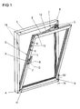
- Figure 1 shows a window with a mounted on a frame 1 Wing 2 and with a drive rod fitting 3 in a tilted position, wherein the wing 1 to a horizontal Tilting axis 4 is shown tilted.
- the espagnolette fitting 3 is driven by a handle 5.
- the Wing 2 can be about a vertical axis of rotation 6 in one Turn the rotary position.
- the wing 2 can be in lock a closed position lying in the frame 1 and move to a night ventilation position, in the the plane of the wing 2 a gap far from the frame. 1 is removed.
- the handle 5 has several positions, where Z is the closed position, D is the rotational position, with K the tilted position and with L the night ventilation position of the espagnolette fitting 3 is marked.
- the wing 2 of a Ausstellschere 7 held. At the intersection of the axes 4, 6, the window has a corner bearing 8.
- the Ausstellschere 7 has a pivot bearing 9 on the frame first hinged extension arm 10, while the wing 2 at his lower horizontal spar has a tilting bearing 11.
- drive rod 12th About the drive rod 12 are a plurality of locking pin 13th drivable.
- the locking pin 13 are closing plates 14th opposite, which provided the locking pin 13 in Engage behind positions with positive locking.
- FIG. 2 shows greatly enlarged the in tilted position Espagnolette fitting 3 in the area of the pivot bearing 9 of the Ausstellschere 7 of Figure 1 in against the Frame 1 pressed wing 2.
- a strike plate 15 which is arranged with a on the drive rod 12 Locking pin 16 cooperates.
- the striking plate 15 has a recess in the region of the tilting position K shown 17 for performing the lock pin 16.
- In the Night ventilation position is the locking pin 16th in the position marked L and penetrates into one Pocket 18 of the strike plate 15 and connects the wing 2 with the pivot bearing 9.
- the locking pin 16 also has at its free end a radial widening 19, with he an edge 20 of the striker plate 15 of the pivot bearing 9 in gap ventilation position L engages behind. Furthermore is shown in Figure 2 that the strike plate 15 of the Drehlagers 9 another pocket 21 for receiving the Locking pin 16 in the closed position Z and rotational position D has.
- Figure 3 shows in a sectional view through the Espagnolette fitting 3 of Figure 2 that the bag 18th for receiving the locking pin 16 in the night ventilation position L a leading edge 22 for the locking pin 16th Has.
- the leading edge 22 points from the plane of the Locking pin 16 in the closed position Z to the plane of Locking pin 16 in the night ventilation position L out.
- FIG 4 shows in a view from position IV on the Espagnolette fitting 3 from Figure 2 that one on the stay 10 of Ausstellschere 7 arranged strike plate 23 has two pockets 24, 25, which another Locking pin 26 in night ventilation position L, rotational position D and closed position Z engage behind a positive fit.
- the illustrated tilt position K has the Striker plate 23 a recess 27 for moving out of Locking pin 26.
- the levels of pockets 24, 25 are transverse to each other to the direction of movement of the illustrated in Figure 2 Driving rod 12 offset and a leading edge 28, so that shown in Figure 1 Wing 2 in the gap ventilation position L a distance to the frame 1 and in the closed position Z tight in the frame 1 lies.
- FIG. 5 shows the corner bearing 8 from FIG. 1 in one Sectional view along the line V - V.
- the corner bearing 8 has a pivot pin 29 on the axis of rotation 6, on the a fixed to the wing 2 sleeve 30 rotatably mounted is. Furthermore, the corner bearing 8 has a perpendicular to the plane pointing axis 31, which is a tilting of the wing 2 allows for the tilting axis 4 shown in Figure 1.
- An axis 31 supporting ab passionnden bracket 32 is in a longitudinal guide 33 of the frame 1 is held.
- the longitudinal guide 33 allows movement of the wing 2 of the Frame 1 away by the distance a in the night ventilation position. This distance a preferably corresponds at least the offset of the pockets 18, 21, 24, 25 of the strike plates 15, 23 from FIGS. 3 and 4.
Landscapes
- Engineering & Computer Science (AREA)
- Mechanical Engineering (AREA)
- Specific Sealing Or Ventilating Devices For Doors And Windows (AREA)
- Air-Flow Control Members (AREA)
- Polysaccharides And Polysaccharide Derivatives (AREA)
- Portable Nailing Machines And Staplers (AREA)
- Hinges (AREA)
Abstract
Description
- Fig. 1
- ein Fenster in Kippstellung mit einem erfindungsgemäßen Treibstangenbeschlag,
- Fig. 2
- eine stark vergrößerte Darstellung des Treibstangenbeschlages im Bereich eines Drehlagers einer Ausstellschere,
- Fig. 3
- eine Schnittdarstellung durch den Treibstangenbeschlag aus Figur 2 entlang der Linie III - III,
- Fig. 4
- eine Ansicht von Position IV auf den Treibstangenbeschlag aus Figur 2,
- Fig. 5
- eine Schnittdarstellung durch ein Ecklager des Treibstangenbeschlages aus Figur 1 entlang der Linie V - V.
Claims (9)
- Treibstangenbeschlag zur Verriegelung eines in einem Rahmen liegenden Flügels eines Fensters, einer Fenstertür oder dergleichen mit einer angetriebenen, an dem Flügel oder dem Blendrahmen anzuordnenden Treibstange, mit auf der Treibstange angeordneten Schließzapfen, mit den Schließzapfen gegenüberstehend anzuordnenden Schließblechen und mit einer Spaltlüftungsstellung, in der die Schließzapfen gegenüber ihrer Lage in einer Schließstellung quer zur Bewegungsrichtung der Treibstange versetzt in dem Schließblech angeordnet sind und der Flügel im montierten Zustand einen Abstand zu dem Rahmen hat, dadurch gekennzeichnet, dass zumindest eines der Schließbleche (15) auf einem Drehlager (9) eines Ausstellarms (10) einer Ausstellschere (7) für eine Kippstellung (K) und eine Drehstellung (D) des Flügels (2) angeordnet ist und eine Tasche (18) zur Aufnahme des Schließzapfens (16) in der Spaltlüftungsstellung (L) aufweist.
- Treibstangenbeschlag nach Anspruch 1, dadurch gekennzeichnet, dass das Schließblech (15) unmittelbar in einem Bandlappen (9a) des Drehlagers (9) ausgebildet ist.
- Treibstangenbeschlag nach Anspruch 1 oder 2, dadurch gekennzeichnet, dass die Tasche (18) des auf dem Drehlager (9) angeordneten Schließblechs (15) in Richtung der Drehachse (6) des Drehlagers (9) offen ist.
- Treibstangenbeschlag nach einem der Ansprüche 1 bis 3, dadurch gekennzeichnet, dass das auf dem Drehlager (9) angeordnete Schließblech (15) eine zweite Tasche (21) zur Aufnahme des Schließzapfens (16) in Schließstellung (Z) hat.
- Treibstangenbeschlag nach zumindest einem der vorhergehenden Ansprüche, dadurch gekennzeichnet, dass die Tasche (18) eine Führungskante (22) für den Schließzapfen (16) hat und dass die Führungskante (22) von der Ebene der Schließzapfen (16) in Schließstellung (Z) zu der Ebene der Schließzapfen (16) in Spaltlüftungsstellung (L) weist.
- Treibstangenbeschlag nach zumindest einem der vorhergehenden Ansprüche, dadurch gekennzeichnet, dass der Schließzapfen (16) an seinem freien Ende eine radiale Verbreiterung (19) aufweist und das an dem Drehlager (9) angeordnete Schließblech (15) einen Rand (20) zur Hintergreifung der radialen Verbreiterung (19) hat.
- Treibstangenbeschlag nach zumindest einem der vorhergehenden Ansprüche, dadurch gekennzeichnet, dass an dem Ausstellarm (10) ein weiteres Schließblech (23) angeordnet ist und dass das weitere Schließblech (23) eine Tasche (24) zur Aufnahme eines Schließzapfens (26) in der Spaltlüftungsstellung (L) hat.
- Treibstangenbeschlag nach zumindest einem der vorhergehenden Ansprüche, dadurch gekennzeichnet, dass die Tasche (24) des an dem Ausstellarm (10) angeordneten Schließblechs (15) gegenüber einer Tasche (15) zur Aufnahme des Schließzapfens (26) in Schließstellung versetzt angeordnet ist und dass zwischen den Taschen (24, 25) eine Führungskante (28) angeordnet ist.
- Treibstangenbeschlag nach zumindest einem der vorhergehenden Ansprüche, dadurch gekennzeichnet, dass die Spaltlüftungsstellung (L) und die Schließstellung (Z) jeweils als Endanschlag der Treibstange (12) ausgebildet sind.
Applications Claiming Priority (2)
| Application Number | Priority Date | Filing Date | Title |
|---|---|---|---|
| DE102004014508A DE102004014508A1 (de) | 2004-03-25 | 2004-03-25 | Treibstangenbeschlag |
| DE102004014508 | 2004-03-25 |
Publications (3)
| Publication Number | Publication Date |
|---|---|
| EP1580381A2 true EP1580381A2 (de) | 2005-09-28 |
| EP1580381A3 EP1580381A3 (de) | 2009-04-01 |
| EP1580381B1 EP1580381B1 (de) | 2010-06-02 |
Family
ID=34854033
Family Applications (1)
| Application Number | Title | Priority Date | Filing Date |
|---|---|---|---|
| EP05101648A Expired - Lifetime EP1580381B1 (de) | 2004-03-25 | 2005-03-03 | Treibstangenbeschlag |
Country Status (3)
| Country | Link |
|---|---|
| EP (1) | EP1580381B1 (de) |
| AT (1) | ATE470040T1 (de) |
| DE (2) | DE102004014508A1 (de) |
Cited By (2)
| Publication number | Priority date | Publication date | Assignee | Title |
|---|---|---|---|---|
| EP1785562A3 (de) * | 2005-11-15 | 2009-08-05 | GSG INTERNATIONAL S.p.A. | Seitlich angelenkter Flügel einer Tür oder eines Fensters |
| EP2505744A3 (de) * | 2011-03-30 | 2018-04-11 | HAUTAU GmbH | Schließplatte für einen von einem Blendrahmen abstellbaren Fenster- oder Türflügel |
Families Citing this family (4)
| Publication number | Priority date | Publication date | Assignee | Title |
|---|---|---|---|---|
| DE102010022547A1 (de) * | 2010-06-02 | 2011-12-08 | Roto Frank Ag | Fenster oder dergleichen mit einem Beschlag, Beschlag, Verfahren zum Offenfeststellen eines Fensters oder dergleichen sowie Anwendung des Verfahrens bei einem Fenster oder dergleichen |
| DE102013222100A1 (de) * | 2013-10-30 | 2015-04-30 | Maco Technologie Gmbh | Schließteil |
| CN104373024B (zh) * | 2014-11-13 | 2016-06-15 | 广东坚朗五金制品股份有限公司 | 门窗微通风结构 |
| DE102022201672A1 (de) | 2022-02-17 | 2023-08-17 | Aug. Winkhaus Gmbh & Co. Kg | Treibstangenbeschlag und Fenster, Fenstertür oder dgl. mit rahmenartig zusammengesetzten Holmen und mit einem solchen Treibstangenbeschlag |
Citations (3)
| Publication number | Priority date | Publication date | Assignee | Title |
|---|---|---|---|---|
| DE1259222B (de) | 1964-01-18 | 1968-01-18 | Jaeger Frank K G | Betaetigungsvorrichtung zum OEffnen und Schliessen eines um eine waagerechte Achse kippbaren oder klappbaren Fluegels, insbesondere von Kipp-Schwenkfluegelfenstern, -tueren od. dgl. |
| EP0051309A2 (de) | 1980-11-03 | 1982-05-12 | Aug. Winkhaus GmbH & Co. KG | Fenster |
| DE3043925C2 (de) | 1980-11-03 | 1994-09-29 | Winkhaus Fa August | Vorrichtung an einem Fenster zur Einstellung des Flügelrahmens in eine Spaltöffnungsstellung |
Family Cites Families (2)
| Publication number | Priority date | Publication date | Assignee | Title |
|---|---|---|---|---|
| DE19825071C2 (de) * | 1998-06-04 | 2002-06-27 | Esco Metallbaubeschlag Handel Gmbh | Parallelausstellfenster mit Drehfunktion |
| DE10162659A1 (de) * | 2001-12-20 | 2003-07-03 | Winkhaus Fa August | Drehkippfenster |
-
2004
- 2004-03-25 DE DE102004014508A patent/DE102004014508A1/de not_active Withdrawn
-
2005
- 2005-03-03 AT AT05101648T patent/ATE470040T1/de active
- 2005-03-03 DE DE502005009663T patent/DE502005009663D1/de not_active Expired - Lifetime
- 2005-03-03 EP EP05101648A patent/EP1580381B1/de not_active Expired - Lifetime
Patent Citations (3)
| Publication number | Priority date | Publication date | Assignee | Title |
|---|---|---|---|---|
| DE1259222B (de) | 1964-01-18 | 1968-01-18 | Jaeger Frank K G | Betaetigungsvorrichtung zum OEffnen und Schliessen eines um eine waagerechte Achse kippbaren oder klappbaren Fluegels, insbesondere von Kipp-Schwenkfluegelfenstern, -tueren od. dgl. |
| EP0051309A2 (de) | 1980-11-03 | 1982-05-12 | Aug. Winkhaus GmbH & Co. KG | Fenster |
| DE3043925C2 (de) | 1980-11-03 | 1994-09-29 | Winkhaus Fa August | Vorrichtung an einem Fenster zur Einstellung des Flügelrahmens in eine Spaltöffnungsstellung |
Cited By (2)
| Publication number | Priority date | Publication date | Assignee | Title |
|---|---|---|---|---|
| EP1785562A3 (de) * | 2005-11-15 | 2009-08-05 | GSG INTERNATIONAL S.p.A. | Seitlich angelenkter Flügel einer Tür oder eines Fensters |
| EP2505744A3 (de) * | 2011-03-30 | 2018-04-11 | HAUTAU GmbH | Schließplatte für einen von einem Blendrahmen abstellbaren Fenster- oder Türflügel |
Also Published As
| Publication number | Publication date |
|---|---|
| DE102004014508A1 (de) | 2005-12-15 |
| ATE470040T1 (de) | 2010-06-15 |
| EP1580381A3 (de) | 2009-04-01 |
| EP1580381B1 (de) | 2010-06-02 |
| DE502005009663D1 (de) | 2010-07-15 |
Similar Documents
| Publication | Publication Date | Title |
|---|---|---|
| EP0570945B1 (de) | Verdeckt eingebautes Scharniergelenk | |
| DE3442364C1 (de) | Verdeckt im Falz angeordneter Beschlag für Kipp-Schwenkflügelfenster oder -türen | |
| DE3022163A1 (de) | Dreh-kipp-beschlag fuer fenster, tueren o.dgl. mit spaltlueftung | |
| EP1580381B1 (de) | Treibstangenbeschlag | |
| EP0531626B1 (de) | Beschlag für insb. zwangsweise kipp- und parallel abstellbare Flügel | |
| EP0905343B1 (de) | Fenster- oder Türanordung | |
| EP1422372B1 (de) | Fenster oder Tür | |
| DE3617216C2 (de) | ||
| DE19906071C2 (de) | Drehbegrenzer für Dreh-Schiebe-Fenster | |
| EP1580380A2 (de) | Treibstangenbeschlag | |
| EP0054213A2 (de) | Ausstellvorrichtung für Fenster oder Türen mit einem in der Längsachse des oberen Flügelrahmenholms verstellbaren Scherengehäuse | |
| DE9409388U1 (de) | Dreh-Kipp-Beschlag für Fenster, Türen o.dgl. | |
| EP1498563B1 (de) | Spaltlüftungsvorrichtung | |
| DE4333724A1 (de) | Fensterflügel oder dergleichen | |
| EP1178174B1 (de) | Schiebebeschlag für Fenster, Türen od. dgl. | |
| EP0686749B1 (de) | Dreh-Kipp-Beschlag für Fenster, Türen oder dergleichen | |
| DE1584081C3 (de) | Ausstellvorrichtung für Dreh-Kippfenster, Türen o.dgl | |
| EP1715125A2 (de) | Drehkipp- bzw. Kippdrehfensterbeschlag mit Spaltlüftungsstellung | |
| EP1533454B1 (de) | Treibstangenbeschlag | |
| EP1780362B1 (de) | Motorischer Antrieb für schwenkbaren Flügel | |
| EP1267026B1 (de) | Beschlag für ein Fenster, eine Tür oder dergleichen umfassend einen Beschlagarm, eine Treibstange und eine Spaltlüftvorrichtung sowie Fenster, Tür oder dergleichen mit einem solchen Beschlag | |
| DE3905995C2 (de) | ||
| EP1503013A2 (de) | Fenster | |
| DE1784611A1 (de) | Ausstellvorrichtung fuer Schwenk-Kipp-Fenster,Tueren od.dgl. | |
| DE1962906C3 (de) | Beschlag fur Dreh-Kipp- oder Dreh-Klappfenster |
Legal Events
| Date | Code | Title | Description |
|---|---|---|---|
| PUAI | Public reference made under article 153(3) epc to a published international application that has entered the european phase |
Free format text: ORIGINAL CODE: 0009012 |
|
| AK | Designated contracting states |
Kind code of ref document: A2 Designated state(s): AT BE BG CH CY CZ DE DK EE ES FI FR GB GR HU IE IS IT LI LT LU MC NL PL PT RO SE SI SK TR |
|
| AX | Request for extension of the european patent |
Extension state: AL BA HR LV MK YU |
|
| PUAL | Search report despatched |
Free format text: ORIGINAL CODE: 0009013 |
|
| AK | Designated contracting states |
Kind code of ref document: A3 Designated state(s): AT BE BG CH CY CZ DE DK EE ES FI FR GB GR HU IE IS IT LI LT LU MC NL PL PT RO SE SI SK TR |
|
| AX | Request for extension of the european patent |
Extension state: AL BA HR LV MK YU |
|
| 17P | Request for examination filed |
Effective date: 20090827 |
|
| 17Q | First examination report despatched |
Effective date: 20091028 |
|
| AKX | Designation fees paid |
Designated state(s): AT BE BG CH CY CZ DE DK EE ES FI FR GB GR HU IE IS IT LI LT LU MC NL PL PT RO SE SI SK TR |
|
| GRAP | Despatch of communication of intention to grant a patent |
Free format text: ORIGINAL CODE: EPIDOSNIGR1 |
|
| GRAS | Grant fee paid |
Free format text: ORIGINAL CODE: EPIDOSNIGR3 |
|
| GRAA | (expected) grant |
Free format text: ORIGINAL CODE: 0009210 |
|
| AK | Designated contracting states |
Kind code of ref document: B1 Designated state(s): AT BE BG CH CY CZ DE DK EE ES FI FR GB GR HU IE IS IT LI LT LU MC NL PL PT RO SE SI SK TR |
|
| REG | Reference to a national code |
Ref country code: GB Ref legal event code: FG4D Free format text: NOT ENGLISH |
|
| REG | Reference to a national code |
Ref country code: CH Ref legal event code: EP |
|
| REG | Reference to a national code |
Ref country code: IE Ref legal event code: FG4D Free format text: LANGUAGE OF EP DOCUMENT: GERMAN |
|
| REF | Corresponds to: |
Ref document number: 502005009663 Country of ref document: DE Date of ref document: 20100715 Kind code of ref document: P |
|
| REG | Reference to a national code |
Ref country code: NL Ref legal event code: VDEP Effective date: 20100602 |
|
| PG25 | Lapsed in a contracting state [announced via postgrant information from national office to epo] |
Ref country code: LT Free format text: LAPSE BECAUSE OF FAILURE TO SUBMIT A TRANSLATION OF THE DESCRIPTION OR TO PAY THE FEE WITHIN THE PRESCRIBED TIME-LIMIT Effective date: 20100602 Ref country code: SE Free format text: LAPSE BECAUSE OF FAILURE TO SUBMIT A TRANSLATION OF THE DESCRIPTION OR TO PAY THE FEE WITHIN THE PRESCRIBED TIME-LIMIT Effective date: 20100602 |
|
| LTIE | Lt: invalidation of european patent or patent extension |
Effective date: 20100602 |
|
| PG25 | Lapsed in a contracting state [announced via postgrant information from national office to epo] |
Ref country code: SI Free format text: LAPSE BECAUSE OF FAILURE TO SUBMIT A TRANSLATION OF THE DESCRIPTION OR TO PAY THE FEE WITHIN THE PRESCRIBED TIME-LIMIT Effective date: 20100602 Ref country code: FI Free format text: LAPSE BECAUSE OF FAILURE TO SUBMIT A TRANSLATION OF THE DESCRIPTION OR TO PAY THE FEE WITHIN THE PRESCRIBED TIME-LIMIT Effective date: 20100602 |
|
| PG25 | Lapsed in a contracting state [announced via postgrant information from national office to epo] |
Ref country code: PL Free format text: LAPSE BECAUSE OF FAILURE TO SUBMIT A TRANSLATION OF THE DESCRIPTION OR TO PAY THE FEE WITHIN THE PRESCRIBED TIME-LIMIT Effective date: 20100602 Ref country code: GR Free format text: LAPSE BECAUSE OF FAILURE TO SUBMIT A TRANSLATION OF THE DESCRIPTION OR TO PAY THE FEE WITHIN THE PRESCRIBED TIME-LIMIT Effective date: 20100903 Ref country code: CY Free format text: LAPSE BECAUSE OF FAILURE TO SUBMIT A TRANSLATION OF THE DESCRIPTION OR TO PAY THE FEE WITHIN THE PRESCRIBED TIME-LIMIT Effective date: 20100602 |
|
| REG | Reference to a national code |
Ref country code: IE Ref legal event code: FD4D |
|
| PG25 | Lapsed in a contracting state [announced via postgrant information from national office to epo] |
Ref country code: NL Free format text: LAPSE BECAUSE OF FAILURE TO SUBMIT A TRANSLATION OF THE DESCRIPTION OR TO PAY THE FEE WITHIN THE PRESCRIBED TIME-LIMIT Effective date: 20100602 Ref country code: IE Free format text: LAPSE BECAUSE OF FAILURE TO SUBMIT A TRANSLATION OF THE DESCRIPTION OR TO PAY THE FEE WITHIN THE PRESCRIBED TIME-LIMIT Effective date: 20100602 Ref country code: EE Free format text: LAPSE BECAUSE OF FAILURE TO SUBMIT A TRANSLATION OF THE DESCRIPTION OR TO PAY THE FEE WITHIN THE PRESCRIBED TIME-LIMIT Effective date: 20100602 |
|
| PG25 | Lapsed in a contracting state [announced via postgrant information from national office to epo] |
Ref country code: CZ Free format text: LAPSE BECAUSE OF FAILURE TO SUBMIT A TRANSLATION OF THE DESCRIPTION OR TO PAY THE FEE WITHIN THE PRESCRIBED TIME-LIMIT Effective date: 20100602 Ref country code: SK Free format text: LAPSE BECAUSE OF FAILURE TO SUBMIT A TRANSLATION OF THE DESCRIPTION OR TO PAY THE FEE WITHIN THE PRESCRIBED TIME-LIMIT Effective date: 20100602 Ref country code: RO Free format text: LAPSE BECAUSE OF FAILURE TO SUBMIT A TRANSLATION OF THE DESCRIPTION OR TO PAY THE FEE WITHIN THE PRESCRIBED TIME-LIMIT Effective date: 20100602 Ref country code: PT Free format text: LAPSE BECAUSE OF FAILURE TO SUBMIT A TRANSLATION OF THE DESCRIPTION OR TO PAY THE FEE WITHIN THE PRESCRIBED TIME-LIMIT Effective date: 20101004 Ref country code: IS Free format text: LAPSE BECAUSE OF FAILURE TO SUBMIT A TRANSLATION OF THE DESCRIPTION OR TO PAY THE FEE WITHIN THE PRESCRIBED TIME-LIMIT Effective date: 20101002 |
|
| PG25 | Lapsed in a contracting state [announced via postgrant information from national office to epo] |
Ref country code: IT Free format text: LAPSE BECAUSE OF FAILURE TO SUBMIT A TRANSLATION OF THE DESCRIPTION OR TO PAY THE FEE WITHIN THE PRESCRIBED TIME-LIMIT Effective date: 20100602 |
|
| PLBE | No opposition filed within time limit |
Free format text: ORIGINAL CODE: 0009261 |
|
| STAA | Information on the status of an ep patent application or granted ep patent |
Free format text: STATUS: NO OPPOSITION FILED WITHIN TIME LIMIT |
|
| PG25 | Lapsed in a contracting state [announced via postgrant information from national office to epo] |
Ref country code: DK Free format text: LAPSE BECAUSE OF FAILURE TO SUBMIT A TRANSLATION OF THE DESCRIPTION OR TO PAY THE FEE WITHIN THE PRESCRIBED TIME-LIMIT Effective date: 20100602 |
|
| 26N | No opposition filed |
Effective date: 20110303 |
|
| PGFP | Annual fee paid to national office [announced via postgrant information from national office to epo] |
Ref country code: FR Payment date: 20110401 Year of fee payment: 7 |
|
| REG | Reference to a national code |
Ref country code: DE Ref legal event code: R097 Ref document number: 502005009663 Country of ref document: DE Effective date: 20110302 |
|
| BERE | Be: lapsed |
Owner name: AUG. WINKHAUS G.M.B.H. & CO. KG Effective date: 20110331 |
|
| PG25 | Lapsed in a contracting state [announced via postgrant information from national office to epo] |
Ref country code: MC Free format text: LAPSE BECAUSE OF NON-PAYMENT OF DUE FEES Effective date: 20110331 |
|
| REG | Reference to a national code |
Ref country code: CH Ref legal event code: PL |
|
| GBPC | Gb: european patent ceased through non-payment of renewal fee |
Effective date: 20110303 |
|
| PG25 | Lapsed in a contracting state [announced via postgrant information from national office to epo] |
Ref country code: BE Free format text: LAPSE BECAUSE OF NON-PAYMENT OF DUE FEES Effective date: 20110331 |
|
| PG25 | Lapsed in a contracting state [announced via postgrant information from national office to epo] |
Ref country code: CH Free format text: LAPSE BECAUSE OF NON-PAYMENT OF DUE FEES Effective date: 20110331 Ref country code: LI Free format text: LAPSE BECAUSE OF NON-PAYMENT OF DUE FEES Effective date: 20110331 |
|
| PG25 | Lapsed in a contracting state [announced via postgrant information from national office to epo] |
Ref country code: GB Free format text: LAPSE BECAUSE OF NON-PAYMENT OF DUE FEES Effective date: 20110303 |
|
| PGFP | Annual fee paid to national office [announced via postgrant information from national office to epo] |
Ref country code: DE Payment date: 20120411 Year of fee payment: 8 |
|
| REG | Reference to a national code |
Ref country code: FR Ref legal event code: ST Effective date: 20121130 |
|
| PG25 | Lapsed in a contracting state [announced via postgrant information from national office to epo] |
Ref country code: FR Free format text: LAPSE BECAUSE OF NON-PAYMENT OF DUE FEES Effective date: 20120402 |
|
| PGFP | Annual fee paid to national office [announced via postgrant information from national office to epo] |
Ref country code: AT Payment date: 20120330 Year of fee payment: 8 |
|
| PG25 | Lapsed in a contracting state [announced via postgrant information from national office to epo] |
Ref country code: LU Free format text: LAPSE BECAUSE OF NON-PAYMENT OF DUE FEES Effective date: 20110303 |
|
| PG25 | Lapsed in a contracting state [announced via postgrant information from national office to epo] |
Ref country code: BG Free format text: LAPSE BECAUSE OF FAILURE TO SUBMIT A TRANSLATION OF THE DESCRIPTION OR TO PAY THE FEE WITHIN THE PRESCRIBED TIME-LIMIT Effective date: 20100902 Ref country code: TR Free format text: LAPSE BECAUSE OF FAILURE TO SUBMIT A TRANSLATION OF THE DESCRIPTION OR TO PAY THE FEE WITHIN THE PRESCRIBED TIME-LIMIT Effective date: 20100602 |
|
| PG25 | Lapsed in a contracting state [announced via postgrant information from national office to epo] |
Ref country code: HU Free format text: LAPSE BECAUSE OF FAILURE TO SUBMIT A TRANSLATION OF THE DESCRIPTION OR TO PAY THE FEE WITHIN THE PRESCRIBED TIME-LIMIT Effective date: 20100602 Ref country code: ES Free format text: LAPSE BECAUSE OF FAILURE TO SUBMIT A TRANSLATION OF THE DESCRIPTION OR TO PAY THE FEE WITHIN THE PRESCRIBED TIME-LIMIT Effective date: 20100913 |
|
| REG | Reference to a national code |
Ref country code: AT Ref legal event code: MM01 Ref document number: 470040 Country of ref document: AT Kind code of ref document: T Effective date: 20130303 |
|
| REG | Reference to a national code |
Ref country code: DE Ref legal event code: R119 Ref document number: 502005009663 Country of ref document: DE Effective date: 20131001 |
|
| PG25 | Lapsed in a contracting state [announced via postgrant information from national office to epo] |
Ref country code: AT Free format text: LAPSE BECAUSE OF NON-PAYMENT OF DUE FEES Effective date: 20130303 Ref country code: DE Free format text: LAPSE BECAUSE OF NON-PAYMENT OF DUE FEES Effective date: 20131001 |