EP1577966A2 - Dispositif d'accumulateur - Google Patents
Dispositif d'accumulateur Download PDFInfo
- Publication number
- EP1577966A2 EP1577966A2 EP05005882A EP05005882A EP1577966A2 EP 1577966 A2 EP1577966 A2 EP 1577966A2 EP 05005882 A EP05005882 A EP 05005882A EP 05005882 A EP05005882 A EP 05005882A EP 1577966 A2 EP1577966 A2 EP 1577966A2
- Authority
- EP
- European Patent Office
- Prior art keywords
- frames
- accumulator
- abutment portion
- accumulator device
- fitting
- Prior art date
- Legal status (The legal status is an assumption and is not a legal conclusion. Google has not performed a legal analysis and makes no representation as to the accuracy of the status listed.)
- Granted
Links
Images


Classifications
-
- H—ELECTRICITY
- H01—ELECTRIC ELEMENTS
- H01M—PROCESSES OR MEANS, e.g. BATTERIES, FOR THE DIRECT CONVERSION OF CHEMICAL ENERGY INTO ELECTRICAL ENERGY
- H01M50/00—Constructional details or processes of manufacture of the non-active parts of electrochemical cells other than fuel cells, e.g. hybrid cells
- H01M50/20—Mountings; Secondary casings or frames; Racks, modules or packs; Suspension devices; Shock absorbers; Transport or carrying devices; Holders
-
- H—ELECTRICITY
- H01—ELECTRIC ELEMENTS
- H01M—PROCESSES OR MEANS, e.g. BATTERIES, FOR THE DIRECT CONVERSION OF CHEMICAL ENERGY INTO ELECTRICAL ENERGY
- H01M10/00—Secondary cells; Manufacture thereof
- H01M10/04—Construction or manufacture in general
- H01M10/0431—Cells with wound or folded electrodes
-
- H—ELECTRICITY
- H01—ELECTRIC ELEMENTS
- H01M—PROCESSES OR MEANS, e.g. BATTERIES, FOR THE DIRECT CONVERSION OF CHEMICAL ENERGY INTO ELECTRICAL ENERGY
- H01M10/00—Secondary cells; Manufacture thereof
- H01M10/60—Heating or cooling; Temperature control
- H01M10/61—Types of temperature control
- H01M10/613—Cooling or keeping cold
-
- H—ELECTRICITY
- H01—ELECTRIC ELEMENTS
- H01M—PROCESSES OR MEANS, e.g. BATTERIES, FOR THE DIRECT CONVERSION OF CHEMICAL ENERGY INTO ELECTRICAL ENERGY
- H01M50/00—Constructional details or processes of manufacture of the non-active parts of electrochemical cells other than fuel cells, e.g. hybrid cells
- H01M50/20—Mountings; Secondary casings or frames; Racks, modules or packs; Suspension devices; Shock absorbers; Transport or carrying devices; Holders
- H01M50/204—Racks, modules or packs for multiple batteries or multiple cells
- H01M50/207—Racks, modules or packs for multiple batteries or multiple cells characterised by their shape
- H01M50/211—Racks, modules or packs for multiple batteries or multiple cells characterised by their shape adapted for pouch cells
-
- H—ELECTRICITY
- H01—ELECTRIC ELEMENTS
- H01M—PROCESSES OR MEANS, e.g. BATTERIES, FOR THE DIRECT CONVERSION OF CHEMICAL ENERGY INTO ELECTRICAL ENERGY
- H01M50/00—Constructional details or processes of manufacture of the non-active parts of electrochemical cells other than fuel cells, e.g. hybrid cells
- H01M50/20—Mountings; Secondary casings or frames; Racks, modules or packs; Suspension devices; Shock absorbers; Transport or carrying devices; Holders
- H01M50/258—Modular batteries; Casings provided with means for assembling
-
- H—ELECTRICITY
- H01—ELECTRIC ELEMENTS
- H01M—PROCESSES OR MEANS, e.g. BATTERIES, FOR THE DIRECT CONVERSION OF CHEMICAL ENERGY INTO ELECTRICAL ENERGY
- H01M50/00—Constructional details or processes of manufacture of the non-active parts of electrochemical cells other than fuel cells, e.g. hybrid cells
- H01M50/20—Mountings; Secondary casings or frames; Racks, modules or packs; Suspension devices; Shock absorbers; Transport or carrying devices; Holders
- H01M50/262—Mountings; Secondary casings or frames; Racks, modules or packs; Suspension devices; Shock absorbers; Transport or carrying devices; Holders with fastening means, e.g. locks
- H01M50/264—Mountings; Secondary casings or frames; Racks, modules or packs; Suspension devices; Shock absorbers; Transport or carrying devices; Holders with fastening means, e.g. locks for cells or batteries, e.g. straps, tie rods or peripheral frames
-
- H—ELECTRICITY
- H01—ELECTRIC ELEMENTS
- H01M—PROCESSES OR MEANS, e.g. BATTERIES, FOR THE DIRECT CONVERSION OF CHEMICAL ENERGY INTO ELECTRICAL ENERGY
- H01M50/00—Constructional details or processes of manufacture of the non-active parts of electrochemical cells other than fuel cells, e.g. hybrid cells
- H01M50/30—Arrangements for facilitating escape of gases
-
- Y—GENERAL TAGGING OF NEW TECHNOLOGICAL DEVELOPMENTS; GENERAL TAGGING OF CROSS-SECTIONAL TECHNOLOGIES SPANNING OVER SEVERAL SECTIONS OF THE IPC; TECHNICAL SUBJECTS COVERED BY FORMER USPC CROSS-REFERENCE ART COLLECTIONS [XRACs] AND DIGESTS
- Y02—TECHNOLOGIES OR APPLICATIONS FOR MITIGATION OR ADAPTATION AGAINST CLIMATE CHANGE
- Y02E—REDUCTION OF GREENHOUSE GAS [GHG] EMISSIONS, RELATED TO ENERGY GENERATION, TRANSMISSION OR DISTRIBUTION
- Y02E60/00—Enabling technologies; Technologies with a potential or indirect contribution to GHG emissions mitigation
- Y02E60/10—Energy storage using batteries
-
- Y—GENERAL TAGGING OF NEW TECHNOLOGICAL DEVELOPMENTS; GENERAL TAGGING OF CROSS-SECTIONAL TECHNOLOGIES SPANNING OVER SEVERAL SECTIONS OF THE IPC; TECHNICAL SUBJECTS COVERED BY FORMER USPC CROSS-REFERENCE ART COLLECTIONS [XRACs] AND DIGESTS
- Y02—TECHNOLOGIES OR APPLICATIONS FOR MITIGATION OR ADAPTATION AGAINST CLIMATE CHANGE
- Y02P—CLIMATE CHANGE MITIGATION TECHNOLOGIES IN THE PRODUCTION OR PROCESSING OF GOODS
- Y02P70/00—Climate change mitigation technologies in the production process for final industrial or consumer products
- Y02P70/50—Manufacturing or production processes characterised by the final manufactured product
Definitions
- the present invention relates to an accumulator device including a plurality of connected accumulator cells such as a rechargeable battery, a capacitor, and a generator module.
- a battery pack which is relatively easy to handle and structured by connecting a plurality of small sized accumulator cells (such as a rechargeable battery, a capacitor, and a generator module) is extensively used.
- a main part of the accumulator device (battery pack) of this kind is generally structured by integrally accommodating a predetermined number of accumulator cells (element cells) set depending on voltage and capacity specifications in a package case. (see JP-A-2003-157813).
- the accumulator device is structured by integrally accommodating a number of accumulator cells in a package case
- dedicated package cases must be individually prepared for each specification (e.g. the number of accumulator cells to be accommodated) of a vehicle or the like for mounting the accumulator device thereto on the basis of energy needs of the vehicle.
- new cases will be necessary every time the specification of the vehicle is changed.
- the package case for integrally accommodating the plurality of accumulator cells as described above must have strength over a prescribed level in general so as to protect the accumulator cells from externally applied impacts or the like.
- the structure could be complicated or the weight could be increased.
- the present invention has been made in consideration of the above described disadvantages, and it is an object of the present invention to provide an accumulator device that has a highly versatile and simple structure and can surely protect the accumulator cells from external impacts.
- An accumulator device comprises a plurality of substantially identical and flat frames.
- Each of the frames comprises: an accommodating portion for accommodating an accumulator cell; a first abutment portion on an adverse surface of each of the frames; a second abutment portion on a reverse surface of each of the frames; a first fitting structure on the first abutment portion; and a second fitting structure on the second abutment portion.
- the plurality of frames are stacked by contacting adjacent ones of the plurality of frames by the first abutment portion of one of the adjacent frames and the second abutment portion of another of the adj acent frames.
- the adjacent frames are commonly coupled by fitting the first fitting structure of the one of the adjacent frames to the second fitting structure of the another of the adjacent frames.
- the accumulator cell accommodated in the accommodating portion of the one of the adjacent frames is held between the one of the adjacent frames and the another of the adjacent frames.
- the accumulator cell may be a laminate cell, and a sealing portion of the laminate cell positioned in the accommodating portion is between the first abutment portion of the one of the adjacent frames and the second abutment portion of the another of the adjacent frames.
- first abutment portion and the second abutment portion are made of an elastic member.
- each of frames may further comprises a cooling passage structure, so that the cooling passage structures of the plurality of frames are connected to form a continuous cooling passage in a stacking direction of the frames when the plurality of frames are stacked.
- first fitting structure may comprise a fitting projection provided to project at the first abutment portion near one side
- second fitting structure may comprise a fitting recess provided at the second abutment portion near the other side
- a plurality of the accumulator cells are connected in series in advance, each of the plurality of accumulator cells is individually accommodated in the accommodating portions of each of the frames, and the plurality of accumulator cells are arranged in a zigzag arrangement with respect to each other.
- first fitting structure and second fitting structure both comprise electrically conducting contacts, one electrode terminal of the accumulator cell is electrically connected to the first fitting structure, and the other electrode terminal is electrically connected to the second fitting structure, so that the accumulator cell and the frame constitute a module.
- the accumulator device may comprise a cover sheet for at least externally covering coupling portions between the frames, and for reinforcing the coupling portions.
- the cover sheet is an annular heat-shrinkable sheet, and the cover sheet comprises intermittent incisions along the coupling portions or the vicinity of the coupling portions.
- the accumulator device may further comprise an accessory accommodating frame for accommodating an accessory
- the accessory accommodating frame may have substantially the same shape as each of the frame, and the accessory accommodating frame may be stacked on the plurality frames that accommodates the accumulator cell.
- the accumulator device according to the present invention has a highly versatile and simple structure and can surely protect the accumulator cells from external impacts.
- Figs. 1 to 5 relate to a first embodiment of the invention
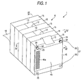
- Fig. 1 is a perspective view of an accumulator device
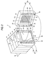
- Fig. 2 is a partly exploded, perspective view of the accumulator device in Fig. 1
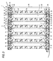
- Fig. 3 is a sectional view taken along line III-III in Fig. 1
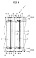
- Fig. 4 is a sectional view taken along line IV-IV in Fig. 1
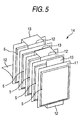
- Fig. 5 is a perspective view of series-connected flat laminate cells.
- the reference numeral 1 represents an accumulator device mounted for example in an electric vehicle (EV), a hybrid electric vehicle (HEV), or a fuel cell vehicle (FCV), and the accumulator device 1 includes a plurality of (five in the shown example) flat laminate cells 5 as the accumulator cells, and a package case 6 that accommodates the flat laminate cells 5.
- EV electric vehicle
- HEV hybrid electric vehicle
- FCV fuel cell vehicle
- a flat laminate cells 5 in a substantially rectangular shape in a plan view are used as the accumulator cells in the embodiment, while other kinds of rechargeable batteries, capacitors, a generator module or the like may be used instead.
- the flat laminate cells 5 used in the embodiment have layers of electrodes and electrolyte enclosed and sealed with a laminate film. A sealing portion 11 is provided around it, and tabs 12 and 13 for positive and negative electrode terminals are provided on the ends.
- the flat laminate cells 5 are connected in series in advance by connecting the tabs 12 and 13 as the terminals, and the series-connected flat laminate cells 5 constitute a continuous cell string 14 (see Fig. 5).
- the package case 6 is essentially made of a plurality of (six in the shown example) substantially identical frames 15 stacked to each other.
- the package case 6 for example, has flat frames 15 of resin in a substantially rectangular shape in a plan view, and there is an opening 17 having a bottom on one surface of the frame 15.
- An elastic member made of a materiel such as low-resilience resin and a urethane foam material is provided around the opening 17 and on both surfaces along the edges, and these elastic members serve as abutment portions 18 and 19 (a first abutment portion 18 and a second abutment portion 19) against the other frames 15. That is, the first abutment portion 18 is provided on a first surface (an adverse surface) of the frame 15, and the second abutment portion 19 is provided on a second surface (a reverse surface) of the frame 15.
- An accommodating portion 20 that accommodates the flat laminate cell 5 is formed in the frame 15 by the opening 17 of the frame 15.
- the abutment portion 18 (the first abutment portion 18) of one frame 15 is, for example, provided with a first fitting structure 27 consisting of a pair of fitting projections 25 (a first fitting projections 25) and a pair of fitting recesses 26 (a first fitting recesses 26), and the abutment portion 19 (the second abutment portion 19) of the other frame is provided with a second fitting structure 30 corresponding to the first fitting structure 27 and consisting of a pair of fitting recesses 29 (asecondfittingrecesses29) andapairoffittingprojections 28 (a second fitting projections 28), so that adjacent frames 15 stacked by contacting by the first abutment portion 18 of one of the adjacent frames 15 and the second abutment portion 19 of another of the adjacent frames 15 are coupled by fitting the first fitting structure 27 of the one of the adjacent frames 15 and the second fitting structure 30 of the another of the adjacent frames 15. (see Figs. 2 and 3)
- pins 32 are respectively implanted and fixed to the through holes 31.
- One end of each of the pins 32 on the side of the second abutment portion 19 is protruded from the corresponding through hole 31, and the one end of each of the pins 32 is provided as the first fitting projection 25.
- Each of the through holes 31 formed in the first abutment portion 18 near the other end in the longitudinal direction of the frame 15 (e.g. a lower end) is provided as the first fitting recess 26.
- pins 33 are respectively implanted and fixed to the through holes 31.
- One end of each of the pins 33 on the side of the first abutment portion 18 is protruded from the corresponding through hole 31, and the one end of each of the pins 33 is provided as the second fitting projection 28.
- Each of the through holes 31 formed in the second abutment portion 19 near the one end (upper end) in the longitudinal direction of the frame 15 is provided as the second fitting recess 29.
- a plurality of engagement grooves 34 are provided on the periphery of each of the fitting projections 25 (28), and the engagement grooves 34 function as a falling-out stopper (a retaining stopper) having prescribed strength between the fitting projections 25 (28) and the fitting recesses 26 (29).
- a so-called semi-locking structure is formed between the fitting projections 25 (28) and the fitting recesses 26 (29).
- the frames 15 each have a cooling passage structure 35 for cooling the flat laminate cells 5 as the accumulator cells accommodated in the accommodating portion 20.
- the cooling passage structure 35 has for example a pair of through portions 36 penetrating through the edge parts on both shorter side direction of the frame 15, a plurality of slits 37 provided at the bottom 17a of the opening 17, and a communication opening 38 to allow the through portions 36 and slits 37 to communicate with each other.
- the cooling passage structures 35 are connected to forma cooling passage 40 connected in a stacking direction in the package case 6 when the frames 15 are stacked. More specifically, cooling air is passed through the cooling passage structures 35, so that the flat laminate cells 5 accommodated in the frames 15 can be cooled. Note that, if a water proof arrangement is provided, a liquid cooling method with a liquid such as water may be used instead of the cooling air.
- the flat laminate cells 5 are individually accommodated.
- the frames 15 accommodating the flat laminate cells 5 are sequentially stacked on one another by contacting adjacent ones of the frames 15 by the first abutment portion 18 of one of the adjacent frames 15 and the second abutment portion 19 of another of the adjacent frames 15, and the adjacent frames 15 are commonly coupled by fitting the first fitting structure 27 of the one of the adjacent frames 15 to the second fitting structure 30 of the another of the adjacent frames 15 (as the first fitting projections 25 and the second fitting recesses 29 and the second fitting projections 28 and the first fitting recesses 26 are fitted with each other) (see Fig. 2).
- the reference character 45a refers to a cooling air inlet 45a opened corresponding to the cooling passage 40 so as to let cooling air into the cooling passage 40 formed in the package case 6.
- the cell string 14 is accommodated in the package case 6 in a manner that the flat laminate cells 5 are arranged in a zigzag arrangement.
- a flat laminate cell 5 accommodated in an accommodating portion 20 is held between a frame 15 and the adjacent frame 15 stacked thereon.
- the frame 15 according to the embodiment is provided so that the total of the depth of the opening 17 and the thickness of the abutment portions 18 and 19 is substantially in coincidence with the thickness of the accumulator cell 5, and the slits 37 forming the bottom 17a of the opening 17 hold the flat laminate cell 5.
- the sealing portion 11 for the flat laminate cell 5 accommodated in the accommodating portion 20 is held between the abutment portion 18 of a frame 15 and the abutment portion 19 of the adjacent frame 15 stacked thereon.
- the abutment portions 18 and 19 are made of an elastic member, so that the flat laminate cells 5 are held elastically in a closely contacted manner between the frames 15, and the sealing portions 11 are also held elastically in a closely contacted manner between the abutment portions 18 and 19. In this way, a contact pressure can be surely loaded to each of the electrodes in the flat laminate cells 5.
- the package case 6 is constituted by a stacking structure of the plurality of substantially identical frames 15, so that the versatility of the accumulator device 1 can be improved. More specifically, simply by increasing/decreasing the number of frames 15 to be stacked to meet energy needs such as voltage and power requirements, the number of flat laminate cells 5 that can be accommodated in the package case 6 can readily be changed. Therefore, different package cases are not necessary depending on the specifications of vehicles to which the cells are applied, and accumulator devices corresponding to various specifications can readily be provided.
- the package case 6 is segmented, so that the flat laminate cells (accumulator cells) 5 can surely be protected from external impacts in a simple structure, and no more reinforcement are required. More specifically, upon application of a prescribed impact on the accumulator device 1, the semi-locking structure between the frames 15 consisting of the first and second fitting structures 27 and 30 is unlocked and the impact is dispersed. Therefore, such an impact transmitted to the flat laminate cells (accumulator cells) 5 canbe reduced without strengthening a whole of the package case 6 more than necessary.
- the flat laminate cells 5 connected in series by connecting the tabs 12 and 13 and arranged in a zigzag arrangement with respect to each other are accommodated in the frames 15. Therefore, a tab (electrode terminal) connecting process, which is cumbersome, is not necessarily carried out, even though each of the flat laminate cells 5 is individually accommodated in the respective frames 15. Moreover, an interconnection process in the accumulator device 1 can rationally be carried out.
- Figs. 6 to 9 relate to the second embodiment of the invention.
- Fig. 6 is a perspective view of an accumulator device
- Fig. 7 is a partly exploded, perspective view of the accumulator device
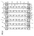
- Fig. 8 is a sectional view taken along line VIII-VIII in Fig. 6,
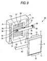
- Fig. 9 is an exploded perspective view of a module.
- the second embodiment is mainly different from the first embodiment in the structures of first and second fitting structures. The other same parts will be denoted by the same reference characters and will not be described.
- the first abutment portion 18 comprises, for example, a first fitting structure 51 consisting of a pair of fitting projections 50
- the second abutment portion 19 comprises a second fitting structure 53 corresponding to the first fitting structure 51 and consisting of a pair of fitting recesses 52 (see Figs. 7 to 9).
- metal pins 55 having good conductivity are respectively implanted and fixed to the through holes 31 provided near one end in the longitudinal direction of the frame 15.
- Each one end of the pins 55 on the side of the first abutment portion 18 is protruded from each of the through holes 31, and the protruded pins 55 are provided to serve as the fitting projections 50.
- metal pins 60 having good conductivity are respectively implanted and fixed to the through holes 31 provided near the other end in the longitudinal direction of the frame 15.
- Each of the metal pins 60 penetrates the frame 15 so that one end of the each of the metal pins 60 is reached to a side of the second abutment portion 19 in each of the through holes 31.
- a recess corresponding to the fitting projection 50 is provided, and each recesses of the each of the pins 60 is provided to serve as a fitting recess 52.
- a bus bar 56 is provided along the first abutment portion 18 between the pair of pins 55.
- a pin 57 is protruded from one surface of the bus bar 56 facing the first abutment portion 18, and the pin 57 is fitted into a hole 58 provided in the frame 15, so that the bus bar 56 can firmly be held at the frame 15.
- a bus bar 62 is provided along the abutment portion 18 between the pair of pins 60.
- the flat laminate cells 5 are individually accommodated.
- Each of the flat laminate cells 5 in the accommodating portions 20 has one tab (for example positive electrode) 12 connected to a bus bar 62 and the other tab (for example negative electrode) 13 connected to the bus bar 56.
- the tabs 12 and 13 are connected, the flat laminate cell 5 is fixed in the frame 15 and forms a module 65 together with the frame 15.
- the electrical connection of the tab 12 with the bus bar 62 allows the fitting recess 52 to serve as a positive electrode contact (electrical conducing contact) and the electrical connection of the tab 13 with the bus bar 56 allows the fitting projection 50 to serve as a negative electrode contact (electrical conducting contact).
- the frames 15 forming the modules 65 are sequentially stacked by contacting the first abutment portion 18 of one of adjacent frames 15 and the second abutment portion 19 of another of the adjacent frames 15, in a manner that the fitting projections 50 are alternately arranged. That is, when one of the fitting projections 50 of the one of the adjacent frames 15 is positioned near an upper end in the longitudinal direction of the one of the adjacent frames 15, another of the fitting projections 50 of the another of the adjacent frames 15 is positioned near a lower end in the longitudinal direction of the another of the adjacent frames 15.
- each fitting projection 50 is opposed to the fitting recess 52 of adjacent frame 15 thereof, and as they are fitted with each other (as the first and second fitting structures 51 and 53 are fitted with each other), the frames 15 (modules 65) are coupled with each other.
- the flat laminate cells 5 are connected in series as the fitting projections 50 and the fitting recesses 52 are fitted with each other.
- a bus bar 66 that connects the bus bar 56 and the bus bar 62 is provided (see Fig. 8).
- the remaining frame 15 is stacked and coupled to one end of a stacking of the modules 65 and the accommodating portion 20 of the remaining frame 15 is closed by a cover 45 (see Figs. 6 and 8).
- a double-faced adhesive tape 67 is inserted between the first abutment portion 18 near the another end in the longitudinal direction of the one of the adjacent frames 15 and the second abutment portion 19 near the one end in the longitudinal direction of the another of the adjacent frames 15. Therefore, the double-faced adhesive tape 67 reinforces a coupling of the frames by the first fitting structure 51 and the second fitting structure 57 (see Fig. 7).
- the fitting projections 50 and the fitting recesses 52 positioned on both ends serve as the negative electrode contact and the positive electrode contact, respectively for the accumulator device 1 as a whole.
- the coupling strength at the coupling portions between the frames 15 can be unequal.
- a weak part can be provided in the coupling part.
- the flat laminate cells (accumulator cells) 5 can effectively be protected from externally applied impacts. More specifically, when an impact in more than a prescribed level is applied to the accumulator device 1, the weak part thus provided surely causes the frames 15 to be separated, and therefore the impact transmitted to the flat laminate cells (accumulator cells) 5 can effectively be reduced.
- the flat laminate cells (accumulator cells) 5 can effectively be protected from damages.
- the accumulator device 1 can have a fuse function without having to add a special component.
- the electrode terminals of the accumulator device 1 and the modules 65 are in non-identical female and male forms by the fitting projections 50 and fitting recesses 52, and therefore a connection mistake at the time of mounting the accumulator device 1 in a vehicle or at the time of stacking the modules 65 can surely be prevented.
- fitting recesses 52 (for example as positive electrode terminals) are provided in the through holes 31 of the frames 15, and therefore electrode terminals in different polarities can surely be prevented from contacting each other, except for a proper fitting.
- Figs. 10 to 13 relate to the third embodiment of the invention.
- Fig. 10 is a perspective view of an accumulator device
- Fig. 11 is a perspective view of the accumulator device in Fig. 10 removed of the cover sheet
- Fig. 12 is a perspective view of a modification of the accumulator device in Fig. 11
- Fig. 13 is a perspective view of another modification of the accumulator device in Fig 11.
- this embodiment is different from the second embodiment in that the coupling between the frames 15 is reinforced using a cover sheet 70.
- the other same parts will be denoted by the same reference characters and will not be described.
- the outer periphery of the frames 15 stacked and coupled with each other is covered with the cover sheet 70.
- the cover sheet 70 is, for example, made of an annular heat-shrinkable sheet 71, and the sheet is thermally shrunk by heat from a blower-dryer or the like (see Fig. 11) to integrally cover the frames 15.
- the thermally shrunk cover sheet 70 integrally covers the frames 15, so that the coupling strength between the frames 15 is reinforced.
- intermittent incisions 72 are provided in the cover sheet 70 along the coupling parts or the vicinity of the coupling parts of the frames 15, so that the coupling strength between the frames 15 may be adjusted as desired.
- the coupling strength between the frames 15 coupled with one another may be reinforced by the cover sheet 70, so that the engagement groove 34 provided at the periphery of the fitting projection 50, and the double-faced adhesive tape 67 inserted between the abutment portions 18 and 19 may be omitted, which can simplify the coupling operation between the frames 15 and improve the productivity of the accumulator device 1.
- cover sheet 70 made of the thermally shrinkable sheet 71 may be employed.
- cover sheet 70 may be made of an adhesive sheet 74 to be wrapped around the coupling parts altogether at the outer periphery of the frames 15.
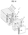
- Fig. 14 relates to the fourth embodiment of the invention.
- Fig. 14 is an exploded perspective view of an accumulator device. This embodiment is mainly different from the second embodiment in that accessories are additionally provided to the stacking of the modules 65. The other same parts will be denoted by the same reference characters and will not be described.
- the accumulator device 1 has, for example, layers of an electronic circuit 75 and a control device 76 as accessories at one end of the stacking of the modules 65.
- the electronic circuit 75 is, for example, a circuit to control the electric energy quantity of the flat laminate cells (accumulator cells) 5.
- the electronic circuit 75 is accommodated and held in an accessory accommodating frame 77 having substantially the same shape as the frame 15, so that an electronic circuit module 78 is formed.
- the control device 76 includes, for example, a relay that controls the connection with a main power supply, and the control device 7 6 is accommodated and held in two accessory accommodating frames 77, so that a control device module 79 is formed.
- the electronic circuit module 78 and the control device module 79 are sequentially placed on the terminal end of the layers of the modules 65 as they are placed and coupled through the frames 15, so that an accumulator device 1 integrally including the various kinds of accessories is formed.
- the accessories associated with the accumulator cells 5 can efficiently be arranged using the frames 15.
- the accumulator cell is not limited to the above-described flat laminate cell, and various kinds may be applied.
- the accumulator device is for use in a vehicle, but it is understood that the invention is not limited to the application.
- the above-described embodiments may be combined as desired.
Landscapes
- Chemical & Material Sciences (AREA)
- Chemical Kinetics & Catalysis (AREA)
- Electrochemistry (AREA)
- General Chemical & Material Sciences (AREA)
- Engineering & Computer Science (AREA)
- Manufacturing & Machinery (AREA)
- Battery Mounting, Suspending (AREA)
- Secondary Cells (AREA)
- Connection Of Batteries Or Terminals (AREA)
- Electric Double-Layer Capacitors Or The Like (AREA)
- Buffer Packaging (AREA)
Applications Claiming Priority (2)
| Application Number | Priority Date | Filing Date | Title |
|---|---|---|---|
| JP2004077638A JP4570888B2 (ja) | 2004-03-18 | 2004-03-18 | 蓄電体装置 |
| JP2004077638 | 2004-03-18 |
Publications (3)
| Publication Number | Publication Date |
|---|---|
| EP1577966A2 true EP1577966A2 (fr) | 2005-09-21 |
| EP1577966A3 EP1577966A3 (fr) | 2011-09-28 |
| EP1577966B1 EP1577966B1 (fr) | 2017-05-17 |
Family
ID=34836568
Family Applications (1)
| Application Number | Title | Priority Date | Filing Date |
|---|---|---|---|
| EP05005882.5A Ceased EP1577966B1 (fr) | 2004-03-18 | 2005-03-17 | Dispositif d'accumulateur |
Country Status (5)
| Country | Link |
|---|---|
| US (1) | US7727667B2 (fr) |
| EP (1) | EP1577966B1 (fr) |
| JP (1) | JP4570888B2 (fr) |
| KR (1) | KR100859538B1 (fr) |
| CN (1) | CN100573975C (fr) |
Cited By (28)
| Publication number | Priority date | Publication date | Assignee | Title |
|---|---|---|---|---|
| WO2011073426A1 (fr) * | 2009-12-18 | 2011-06-23 | Magna E-Car Systems Gmbh & Co Og | Accumulateur |
| WO2011073424A1 (fr) | 2009-12-18 | 2011-06-23 | Magna E-Car Systems Gmbh & Co Og | Élément de refroidissement / chauffage pour accumulateur |
| EP2390941A1 (fr) * | 2010-05-31 | 2011-11-30 | SB LiMotive Co., Ltd. | Bloc de batteries |
| EP2240979A4 (fr) * | 2008-01-18 | 2012-01-25 | Lg Chemical Ltd | Ensemble de cellules de batterie et procédé d'assemblage de l'ensemble de cellules de batterie |
| WO2012038887A3 (fr) * | 2010-09-23 | 2012-06-07 | He3Da S.R.O. | Accumulateur au lithium |
| DE102011101352A1 (de) | 2011-05-12 | 2012-11-15 | Audi Ag | HV-Batterie, insbesondere Traktionsbatterie für ein Fahrzeug |
| US8486552B2 (en) | 2008-06-30 | 2013-07-16 | Lg Chem, Ltd. | Battery module having cooling manifold with ported screws and method for cooling the battery module |
| WO2013131606A1 (fr) * | 2012-03-06 | 2013-09-12 | Audi Ag | Batterie pour un véhicule et procédé de fabrication d'une telle batterie |
| EP2648271A4 (fr) * | 2010-12-01 | 2014-07-02 | Calsonic Kansei Corp | Bloc-batterie |
| US8845762B2 (en) | 2008-04-09 | 2014-09-30 | GM Global Technology Operations LLC | Batteries and components thereof and methods of making and assembling the same |
| US9105950B2 (en) | 2012-03-29 | 2015-08-11 | Lg Chem, Ltd. | Battery system having an evaporative cooling member with a plate portion and a method for cooling the battery system |
| WO2015086669A3 (fr) * | 2013-12-10 | 2015-08-27 | Akasol Gmbh | Élément d'étage, élément latéral, module de refroidissement et procédé de production d'un module de refroidissement |
| US9212745B2 (en) | 2009-07-06 | 2015-12-15 | Carl Freudenberg Kg | Sealing frame for cells in a battery with a thermally active compensating element |
| US9437855B2 (en) | 2008-09-19 | 2016-09-06 | He3Da S.R.O. | Lithium accumulator and the method of producing thereof |
| US9605914B2 (en) | 2012-03-29 | 2017-03-28 | Lg Chem, Ltd. | Battery system and method of assembling the battery system |
| US9627724B2 (en) | 2014-12-04 | 2017-04-18 | Lg Chem, Ltd. | Battery pack having a cooling plate assembly |
| US9647292B2 (en) | 2013-04-12 | 2017-05-09 | Lg Chem, Ltd. | Battery cell assembly and method for manufacturing a cooling fin for the battery cell assembly |
| EP2642553A4 (fr) * | 2010-11-18 | 2017-07-26 | Nissan Motor Co., Ltd | Système d'alimentation électrique stationnaire et procédé de fabrication d'un système d'alimentation électrique stationnaire |
| US9755198B2 (en) | 2015-10-07 | 2017-09-05 | Lg Chem, Ltd. | Battery cell assembly |
| US9759495B2 (en) | 2008-06-30 | 2017-09-12 | Lg Chem, Ltd. | Battery cell assembly having heat exchanger with serpentine flow path |
| US9786894B2 (en) | 2014-11-03 | 2017-10-10 | Lg Chem, Ltd. | Battery pack |
| EP2669917A4 (fr) * | 2011-01-26 | 2018-04-04 | Sumitomo Heavy Industries, Ltd. | Pelle |
| US9960465B2 (en) | 2015-07-30 | 2018-05-01 | Lg Chem, Ltd. | Battery pack |
| US20180233790A1 (en) * | 2017-02-15 | 2018-08-16 | Lg Electronics Inc. | Battery pack |
| US10084218B2 (en) | 2014-05-09 | 2018-09-25 | Lg Chem, Ltd. | Battery pack and method of assembling the battery pack |
| DE102009016576B4 (de) | 2008-04-09 | 2019-06-19 | GM Global Technology Operations LLC (n. d. Ges. d. Staates Delaware) | Batterie |
| DE102009016573B4 (de) | 2008-04-09 | 2020-08-06 | GM Global Technology Operations LLC (n. d. Ges. d. Staates Delaware) | Verfahren zum zusammenbauen einer batterie |
| US10770762B2 (en) | 2014-05-09 | 2020-09-08 | Lg Chem, Ltd. | Battery module and method of assembling the battery module |
Families Citing this family (102)
| Publication number | Priority date | Publication date | Assignee | Title |
|---|---|---|---|---|
| WO2006098242A1 (fr) | 2005-03-17 | 2006-09-21 | Nec Corporation | Dispositif electrique enrobe d’un film et son procede de fabrication |
| US9653748B2 (en) * | 2005-04-14 | 2017-05-16 | Enerdel, Inc. | Apparatus and method for securing battery cell packs |
| JP5227494B2 (ja) * | 2005-06-02 | 2013-07-03 | 株式会社東芝 | 組電池の電池パック |
| WO2006135008A1 (fr) * | 2005-06-17 | 2006-12-21 | Nec Lamilion Energy, Ltd. | Ensemble de dispositifs électriques et dispositif électrique avec une pellicule de couverture extérieure |
| KR100949069B1 (ko) * | 2005-10-14 | 2010-03-25 | 닛본 덴끼 가부시끼가이샤 | 필름-외장 전기 디바이스를 수납하기 위한 시스템 |
| JP4628253B2 (ja) * | 2005-11-04 | 2011-02-09 | Udトラックス株式会社 | 電気二重層キャパシタの自己放電測定システム |
| KR100943833B1 (ko) * | 2005-12-02 | 2010-02-24 | 주식회사 엘지화학 | 중대형 전지팩용 카트리지 |
| JP5098649B2 (ja) | 2005-12-28 | 2012-12-12 | 日本電気株式会社 | 電界効果トランジスタ、ならびに、該電界効果トランジスタの作製に供される多層エピタキシャル膜 |
| KR101212369B1 (ko) * | 2006-01-05 | 2012-12-13 | 에스케이이노베이션 주식회사 | 리튬 2차 전지 시스템의 냉각구조 |
| JP5173182B2 (ja) * | 2006-11-13 | 2013-03-27 | トヨタ自動車株式会社 | 蓄電装置ユニット |
| JP4379467B2 (ja) | 2006-12-11 | 2009-12-09 | 日産自動車株式会社 | 電池モジュール |
| US9196889B2 (en) * | 2007-01-12 | 2015-11-24 | Toyota Jidosha Kabushiki Kaisha | Electrode structure and battery device manufacturing method |
| JP4858203B2 (ja) | 2007-02-07 | 2012-01-18 | トヨタ自動車株式会社 | 自動車 |
| WO2009061451A1 (fr) * | 2007-11-07 | 2009-05-14 | Enerdel, Inc. | Ensemble de batterie avec dispositif de régulation de température |
| FR2929760B1 (fr) * | 2008-04-08 | 2010-10-01 | Vehicules Electr Soc D | Batterie electrique comprenant des elements generateurs souples et un systeme de conditionnement mecanique et thermique desdits elements |
| JP5028346B2 (ja) * | 2008-06-27 | 2012-09-19 | Fdk株式会社 | 蓄電装置 |
| DE102008057210B4 (de) * | 2008-11-13 | 2023-05-04 | Vitesco Technologies GmbH | Zellhalter, Energiespeicherzelle, Zellhalterstapel und Mehrzellenenergiespeicher |
| KR101047991B1 (ko) * | 2008-12-10 | 2011-07-13 | 에스케이이노베이션 주식회사 | 수용부가 형성된 엔드프레임을 갖는 리튬 2차 전지 케이스 및 수용부가 형성된 엔드프레임을 갖는 리튬 2차 전지 셋 |
| JP5113034B2 (ja) | 2008-12-26 | 2013-01-09 | Udトラックス株式会社 | 蓄電デバイス及びモジュール蓄電体 |
| JP5514578B2 (ja) * | 2009-02-24 | 2014-06-04 | 矢崎総業株式会社 | 組電池冷却構造 |
| DE102009010794A1 (de) * | 2009-02-27 | 2010-09-02 | Li-Tec Battery Gmbh | Galvanische Zelle mit Rahmen und Verfahren zu ihrer Herstellung |
| WO2010114317A2 (fr) * | 2009-04-01 | 2010-10-07 | 주식회사 엘지화학 | Module de batterie à excellent rendement et milieu de rayonnement pour ensemble batterie de grande taille |
| KR101047937B1 (ko) * | 2009-05-11 | 2011-07-11 | 주식회사 엘지화학 | 탄성 가압부재를 포함하는 전지 카트리지, 및 이를 포함하는 전지모듈 |
| CN104505476B (zh) * | 2009-05-14 | 2017-09-15 | 株式会社杰士汤浅国际 | 电池组 |
| DE102009031127A1 (de) * | 2009-06-30 | 2011-01-20 | Li-Tec Battery Gmbh | Elektroenergie-Speichervorrichtung aus Flachzellen und Rahmenelementen mit Versorgungskanal |
| DE102009058444A1 (de) * | 2009-12-16 | 2011-06-22 | Li-Tec Battery GmbH, 01917 | Batteriegehäuse zur Aufnahme von elektrochemischen Energiespeichereinrichtungen |
| JP5452204B2 (ja) * | 2009-12-16 | 2014-03-26 | 豊田合成株式会社 | 電池モジュール |
| JP2011134541A (ja) * | 2009-12-24 | 2011-07-07 | Nifco Inc | 連結構造 |
| KR101012049B1 (ko) * | 2010-02-10 | 2011-02-08 | (주)신평 | 범용 보조 배터리팩 |
| JP5491899B2 (ja) * | 2010-02-19 | 2014-05-14 | 株式会社東芝 | 二次電池モジュール |
| US9147916B2 (en) | 2010-04-17 | 2015-09-29 | Lg Chem, Ltd. | Battery cell assemblies |
| US9263713B2 (en) * | 2010-05-26 | 2016-02-16 | Samsung Sdi Co., Ltd. | Battery pack |
| US8343651B2 (en) * | 2010-07-16 | 2013-01-01 | Samsung Sdi Co., Ltd. | Battery pack |
| BR112013005227A2 (pt) | 2010-09-02 | 2016-05-03 | Akasol Engineering Gmbh | "módulo de arrefecimento e método para o fabrico de um módulo de arrefecimento". |
| US8778530B2 (en) * | 2010-09-10 | 2014-07-15 | Samsung Sdi Co., Ltd. | Battery and battery pack using the same |
| JP5786305B2 (ja) | 2010-11-01 | 2015-09-30 | セイコーエプソン株式会社 | カートリッジ連結体、カートリッジホルダ及びプリンター |
| US9812684B2 (en) * | 2010-11-09 | 2017-11-07 | GM Global Technology Operations LLC | Using elastic averaging for alignment of battery stack, fuel cell stack, or other vehicle assembly |
| WO2012101728A1 (fr) * | 2011-01-25 | 2012-08-02 | パナソニック株式会社 | Module de batterie et ensemble à batterie utilisé dans celui-ci |
| KR101255542B1 (ko) * | 2011-05-12 | 2013-04-16 | 삼성에스디아이 주식회사 | 전지 팩 |
| US9793584B2 (en) * | 2011-06-10 | 2017-10-17 | Samsung Sdi Co., Ltd. | Battery module |
| US9061403B2 (en) | 2011-07-21 | 2015-06-23 | GM Global Technology Operations LLC | Elastic tube alignment system for precisely locating an emblem lens to an outer bezel |
| JP5344009B2 (ja) * | 2011-07-28 | 2013-11-20 | トヨタ自動車株式会社 | 電池パック |
| KR20130017289A (ko) * | 2011-08-10 | 2013-02-20 | 현대자동차주식회사 | 고전압 배터리팩용 배터리 모듈 |
| US8900737B2 (en) | 2011-09-08 | 2014-12-02 | Samsung Sdi Co., Ltd. | Energy storage system |
| US9564275B2 (en) * | 2012-03-09 | 2017-02-07 | The Paper Battery Co. | Supercapacitor structures |
| US9067379B2 (en) | 2012-04-28 | 2015-06-30 | GM Global Technologies Operations LLC | Stiffened multi-layer compartment door assembly utilizing elastic averaging |
| JP5459348B2 (ja) * | 2012-05-09 | 2014-04-02 | トヨタ自動車株式会社 | 蓄電装置ユニット |
| US9618026B2 (en) | 2012-08-06 | 2017-04-11 | GM Global Technology Operations LLC | Semi-circular alignment features of an elastic averaging alignment system |
| US9061715B2 (en) | 2012-08-09 | 2015-06-23 | GM Global Technology Operations LLC | Elastic cantilever beam alignment system for precisely aligning components |
| DE102012015816B4 (de) * | 2012-08-10 | 2023-10-26 | Dr. Ing. H.C. F. Porsche Ag | Kraftfahrzeugbatterie |
| US9463538B2 (en) | 2012-08-13 | 2016-10-11 | GM Global Technology Operations LLC | Alignment system and method thereof |
| US9196878B2 (en) * | 2012-11-20 | 2015-11-24 | GM Global Technology Operations LLC | Stackable cartridge module design |
| US9364596B2 (en) * | 2013-01-04 | 2016-06-14 | HeartWave, Inc. | Controller and power source for implantable blood pump |
| US9556890B2 (en) | 2013-01-31 | 2017-01-31 | GM Global Technology Operations LLC | Elastic alignment assembly for aligning mated components and method of reducing positional variation |
| US9156506B2 (en) | 2013-03-27 | 2015-10-13 | GM Global Technology Operations LLC | Elastically averaged alignment system |
| US9382935B2 (en) | 2013-04-04 | 2016-07-05 | GM Global Technology Operations LLC | Elastic tubular attachment assembly for mating components and method of mating components |
| US9388838B2 (en) | 2013-04-04 | 2016-07-12 | GM Global Technology Operations LLC | Elastic retaining assembly for matable components and method of assembling |
| US9278642B2 (en) | 2013-04-04 | 2016-03-08 | GM Global Technology Operations LLC | Elastically deformable flange locator arrangement and method of reducing positional variation |
| JP6238106B2 (ja) * | 2013-04-08 | 2017-11-29 | 株式会社Gsユアサ | 蓄電モジュール、蓄電装置及び風路接続部材 |
| US9297400B2 (en) | 2013-04-08 | 2016-03-29 | GM Global Technology Operations LLC | Elastic mating assembly and method of elastically assembling matable components |
| US9067625B2 (en) | 2013-04-09 | 2015-06-30 | GM Global Technology Operations LLC | Elastic retaining arrangement for jointed components and method of reducing a gap between jointed components |
| US9447840B2 (en) | 2013-06-11 | 2016-09-20 | GM Global Technology Operations LLC | Elastically deformable energy management assembly and method of managing energy absorption |
| US9243655B2 (en) | 2013-06-13 | 2016-01-26 | GM Global Technology Operations LLC | Elastic attachment assembly and method of reducing positional variation and increasing stiffness |
| USD744948S1 (en) * | 2013-07-12 | 2015-12-08 | Motopro Sport v.o.f. | Accumulator |
| US9488205B2 (en) | 2013-07-12 | 2016-11-08 | GM Global Technology Operations LLC | Alignment arrangement for mated components and method |
| US9303667B2 (en) | 2013-07-18 | 2016-04-05 | Gm Global Technology Operations, Llc | Lobular elastic tube alignment system for providing precise four-way alignment of components |
| US9748548B2 (en) * | 2013-07-30 | 2017-08-29 | Johnson Controls Technology Company | Pouch frame with integral circuitry for battery module |
| US9863454B2 (en) | 2013-08-07 | 2018-01-09 | GM Global Technology Operations LLC | Alignment system for providing precise alignment and retention of components of a sealable compartment |
| US20150056009A1 (en) * | 2013-08-23 | 2015-02-26 | GM Global Technology Operations LLC | Elastic averaging snap member aligning and fastening system |
| US9458876B2 (en) | 2013-08-28 | 2016-10-04 | GM Global Technology Operations LLC | Elastically deformable alignment fastener and system |
| US9463831B2 (en) | 2013-09-09 | 2016-10-11 | GM Global Technology Operations LLC | Elastic tube alignment and fastening system for providing precise alignment and fastening of components |
| US9457845B2 (en) | 2013-10-02 | 2016-10-04 | GM Global Technology Operations LLC | Lobular elastic tube alignment and retention system for providing precise alignment of components |
| US9511802B2 (en) | 2013-10-03 | 2016-12-06 | GM Global Technology Operations LLC | Elastically averaged alignment systems and methods |
| US9669774B2 (en) | 2013-10-11 | 2017-06-06 | GM Global Technology Operations LLC | Reconfigurable vehicle interior assembly |
| US9481317B2 (en) | 2013-11-15 | 2016-11-01 | GM Global Technology Operations LLC | Elastically deformable clip and method |
| US9428123B2 (en) | 2013-12-12 | 2016-08-30 | GM Global Technology Operations LLC | Alignment and retention system for a flexible assembly |
| US9447806B2 (en) | 2013-12-12 | 2016-09-20 | GM Global Technology Operations LLC | Self-retaining alignment system for providing precise alignment and retention of components |
| US9216704B2 (en) | 2013-12-17 | 2015-12-22 | GM Global Technology Operations LLC | Elastically averaged strap systems and methods |
| US9599279B2 (en) | 2013-12-19 | 2017-03-21 | GM Global Technology Operations LLC | Elastically deformable module installation assembly |
| US9446722B2 (en) | 2013-12-19 | 2016-09-20 | GM Global Technology Operations LLC | Elastic averaging alignment member |
| US9238488B2 (en) | 2013-12-20 | 2016-01-19 | GM Global Technology Operations LLC | Elastically averaged alignment systems and methods |
| US9541113B2 (en) | 2014-01-09 | 2017-01-10 | GM Global Technology Operations LLC | Elastically averaged alignment systems and methods |
| US9463829B2 (en) | 2014-02-20 | 2016-10-11 | GM Global Technology Operations LLC | Elastically averaged alignment systems and methods |
| US9428046B2 (en) | 2014-04-02 | 2016-08-30 | GM Global Technology Operations LLC | Alignment and retention system for laterally slideably engageable mating components |
| US9657807B2 (en) | 2014-04-23 | 2017-05-23 | GM Global Technology Operations LLC | System for elastically averaging assembly of components |
| KR102210460B1 (ko) * | 2014-04-24 | 2021-02-02 | 에스케이이노베이션 주식회사 | 이차전지용 배터리 셀 조립체 |
| US9429176B2 (en) | 2014-06-30 | 2016-08-30 | GM Global Technology Operations LLC | Elastically averaged alignment systems and methods |
| CN105489828B (zh) * | 2014-09-15 | 2019-11-05 | 比亚迪股份有限公司 | 动力电池模组和具有其的动力电池包 |
| US9484559B2 (en) * | 2014-10-10 | 2016-11-01 | Lg Chem, Ltd. | Battery cell assembly |
| US9758110B2 (en) | 2015-01-12 | 2017-09-12 | GM Global Technology Operations LLC | Coupling system |
| US10107319B2 (en) | 2015-03-02 | 2018-10-23 | GM Global Technology Operations LLC | Elastically averaged alignment systems and methods |
| EP3472878B1 (fr) | 2016-06-20 | 2020-07-15 | Commeo GmbH | Module accumulateur à dissipation thermique optimisée |
| WO2017220515A1 (fr) * | 2016-06-22 | 2017-12-28 | Michael Schnakenberg | Module accumulateur |
| US10431785B2 (en) | 2016-11-30 | 2019-10-01 | Ford Global Technologies, Llc | Battery pack array frames with integrated fastener housings |
| US11394086B2 (en) * | 2017-09-27 | 2022-07-19 | Kabushiki Kaisha Toshiba | Battery module and connection member |
| KR102161287B1 (ko) * | 2017-12-11 | 2020-09-29 | 삼성에스디아이 주식회사 | 배터리 팩 |
| KR102328730B1 (ko) | 2018-04-20 | 2021-11-17 | 주식회사 엘지에너지솔루션 | 직/병렬 연결을 용이하게 하는 구조를 갖는 배터리 모듈 및 이를 포함하는 배터리 팩 |
| KR102716343B1 (ko) * | 2018-05-25 | 2024-10-14 | 주식회사 엘지에너지솔루션 | 배터리 하우징 및 이를 포함하는 배터리 모듈 |
| KR102382382B1 (ko) * | 2018-07-03 | 2022-04-01 | 주식회사 엘지에너지솔루션 | 열수축성 튜브를 포함하는 배터리 모듈 |
| KR102424400B1 (ko) * | 2018-09-13 | 2022-07-22 | 주식회사 엘지에너지솔루션 | 열수축성 튜브를 포함하는 배터리 모듈 |
| WO2020102909A1 (fr) | 2018-11-22 | 2020-05-28 | Corvus Energy Ltd. | Module de batterie et empilement de modules de batterie |
| US11827111B2 (en) | 2021-09-24 | 2023-11-28 | Ford Global Technologies, Llc | Heat shrinkable and stretchable bands for sealing traction battery pack enclosure assemblies |
Family Cites Families (18)
| Publication number | Priority date | Publication date | Assignee | Title |
|---|---|---|---|---|
| JPS566385A (en) * | 1979-06-28 | 1981-01-22 | Yuasa Battery Co Ltd | Air-magnesium cell |
| JPS5856468B2 (ja) * | 1979-07-18 | 1983-12-15 | 株式会社ユアサコーポレーション | 空気−マグネシウム電池 |
| JPS57119458U (fr) * | 1981-01-17 | 1982-07-24 | ||
| JP2732859B2 (ja) * | 1988-07-26 | 1998-03-30 | 松下電器産業株式会社 | 組電池 |
| JPH03133755A (ja) * | 1989-10-13 | 1991-06-06 | Tozo Umeda | 熱収縮性包装材料 |
| JPH04285405A (ja) * | 1991-03-13 | 1992-10-09 | Tadao Totsuka | 電気自動車 |
| FR2700639B1 (fr) * | 1993-01-21 | 1995-04-07 | Bertin & Cie | Batterie d'accumulateurs électriques équipée de moyens d'étanchement perfectionnés. |
| JPH09110069A (ja) * | 1995-08-10 | 1997-04-28 | Dainippon Printing Co Ltd | 乾電池集積包装体とその包装方法 |
| GB9526577D0 (en) * | 1995-12-28 | 1996-02-28 | Nat Power Plc | Method for the fabrication of electrochemical cells |
| JP3627480B2 (ja) * | 1997-11-28 | 2005-03-09 | 松下電器産業株式会社 | 集合電池 |
| JP2000007025A (ja) * | 1998-06-26 | 2000-01-11 | Sony Corp | 包装用品 |
| JP2000090897A (ja) * | 1998-09-17 | 2000-03-31 | Japan Storage Battery Co Ltd | 電池および電池パック |
| JP2001332288A (ja) * | 2000-05-24 | 2001-11-30 | Honda Motor Co Ltd | 燃料電池スタック |
| JP3565271B2 (ja) | 2001-11-19 | 2004-09-15 | 日産自動車株式会社 | 組電池及びその製造方法 |
| CN2519420Y (zh) | 2002-01-10 | 2002-10-30 | 深圳华达电源系统有限公司 | 抗震型叠层式多层蓄电池钢架装置 |
| JP4227762B2 (ja) * | 2002-05-31 | 2009-02-18 | 富士重工業株式会社 | 組電池ユニットおよび組電池ユニットの接続方法 |
| JP4707923B2 (ja) * | 2002-06-17 | 2011-06-22 | パナソニック株式会社 | 組電池 |
| JP3591528B2 (ja) * | 2002-07-23 | 2004-11-24 | 日産自動車株式会社 | モジュール電池 |
-
2004
- 2004-03-18 JP JP2004077638A patent/JP4570888B2/ja not_active Expired - Fee Related
- 2004-12-28 KR KR1020040113786A patent/KR100859538B1/ko not_active Expired - Fee Related
-
2005
- 2005-03-07 US US11/075,175 patent/US7727667B2/en not_active Expired - Fee Related
- 2005-03-17 EP EP05005882.5A patent/EP1577966B1/fr not_active Ceased
- 2005-03-17 CN CNB2005100554094A patent/CN100573975C/zh not_active Expired - Fee Related
Cited By (43)
| Publication number | Priority date | Publication date | Assignee | Title |
|---|---|---|---|---|
| EP2240979A4 (fr) * | 2008-01-18 | 2012-01-25 | Lg Chemical Ltd | Ensemble de cellules de batterie et procédé d'assemblage de l'ensemble de cellules de batterie |
| US8628872B2 (en) | 2008-01-18 | 2014-01-14 | Lg Chem, Ltd. | Battery cell assembly and method for assembling the battery cell assembly |
| DE102009016573B4 (de) | 2008-04-09 | 2020-08-06 | GM Global Technology Operations LLC (n. d. Ges. d. Staates Delaware) | Verfahren zum zusammenbauen einer batterie |
| DE102009016576B4 (de) | 2008-04-09 | 2019-06-19 | GM Global Technology Operations LLC (n. d. Ges. d. Staates Delaware) | Batterie |
| US8845762B2 (en) | 2008-04-09 | 2014-09-30 | GM Global Technology Operations LLC | Batteries and components thereof and methods of making and assembling the same |
| US8486552B2 (en) | 2008-06-30 | 2013-07-16 | Lg Chem, Ltd. | Battery module having cooling manifold with ported screws and method for cooling the battery module |
| US9759495B2 (en) | 2008-06-30 | 2017-09-12 | Lg Chem, Ltd. | Battery cell assembly having heat exchanger with serpentine flow path |
| US10581083B2 (en) | 2008-09-19 | 2020-03-03 | He3Da S.R.O. | Lithium accumulator and the method of producing thereof |
| US9437855B2 (en) | 2008-09-19 | 2016-09-06 | He3Da S.R.O. | Lithium accumulator and the method of producing thereof |
| US9212745B2 (en) | 2009-07-06 | 2015-12-15 | Carl Freudenberg Kg | Sealing frame for cells in a battery with a thermally active compensating element |
| US9401503B2 (en) | 2009-07-06 | 2016-07-26 | Carl Freudenberg Kg | Sealing frame for use in a battery |
| WO2011073424A1 (fr) | 2009-12-18 | 2011-06-23 | Magna E-Car Systems Gmbh & Co Og | Élément de refroidissement / chauffage pour accumulateur |
| US8846227B2 (en) | 2009-12-18 | 2014-09-30 | MAGNA STEYR Battery Systems GmbH & Co. OG | Cooling/heating element for a rechargeable battery |
| WO2011073426A1 (fr) * | 2009-12-18 | 2011-06-23 | Magna E-Car Systems Gmbh & Co Og | Accumulateur |
| US20110293978A1 (en) * | 2010-05-31 | 2011-12-01 | Kim Taeyong | Battery pack |
| EP2390941A1 (fr) * | 2010-05-31 | 2011-11-30 | SB LiMotive Co., Ltd. | Bloc de batteries |
| KR101126889B1 (ko) * | 2010-05-31 | 2012-03-20 | 에스비리모티브 주식회사 | 배터리 팩 |
| US9368769B2 (en) | 2010-05-31 | 2016-06-14 | Samsung Sdi Co., Ltd. | Battery pack |
| RU2577325C2 (ru) * | 2010-09-23 | 2016-03-20 | Гезда С.Р.О. | Литиевый аккумулятор |
| WO2012038887A3 (fr) * | 2010-09-23 | 2012-06-07 | He3Da S.R.O. | Accumulateur au lithium |
| US9203123B2 (en) | 2010-09-23 | 2015-12-01 | He3Da S.R.O. | Lithium accumulator |
| EP2642553A4 (fr) * | 2010-11-18 | 2017-07-26 | Nissan Motor Co., Ltd | Système d'alimentation électrique stationnaire et procédé de fabrication d'un système d'alimentation électrique stationnaire |
| US10230076B2 (en) | 2010-11-18 | 2019-03-12 | Nissan Motor Co., Ltd. | Stationary electric power system and method for manufacturing stationary electric power system including battery body and spacer |
| US9112227B2 (en) | 2010-12-01 | 2015-08-18 | Calsonic Kansei Corporation | Battery pack |
| EP2648271A4 (fr) * | 2010-12-01 | 2014-07-02 | Calsonic Kansei Corp | Bloc-batterie |
| EP2669917A4 (fr) * | 2011-01-26 | 2018-04-04 | Sumitomo Heavy Industries, Ltd. | Pelle |
| US8975774B2 (en) | 2011-05-12 | 2015-03-10 | Audi Ag | HV-battery, in particular traction battery for a vehicle |
| WO2012152444A1 (fr) | 2011-05-12 | 2012-11-15 | Audi Ag | Batterie haute tension, notamment batterie de propulsion pour un véhicule à moteur |
| DE102011101352A1 (de) | 2011-05-12 | 2012-11-15 | Audi Ag | HV-Batterie, insbesondere Traktionsbatterie für ein Fahrzeug |
| WO2013131606A1 (fr) * | 2012-03-06 | 2013-09-12 | Audi Ag | Batterie pour un véhicule et procédé de fabrication d'une telle batterie |
| US9605914B2 (en) | 2012-03-29 | 2017-03-28 | Lg Chem, Ltd. | Battery system and method of assembling the battery system |
| US9105950B2 (en) | 2012-03-29 | 2015-08-11 | Lg Chem, Ltd. | Battery system having an evaporative cooling member with a plate portion and a method for cooling the battery system |
| US9647292B2 (en) | 2013-04-12 | 2017-05-09 | Lg Chem, Ltd. | Battery cell assembly and method for manufacturing a cooling fin for the battery cell assembly |
| WO2015086669A3 (fr) * | 2013-12-10 | 2015-08-27 | Akasol Gmbh | Élément d'étage, élément latéral, module de refroidissement et procédé de production d'un module de refroidissement |
| US10770762B2 (en) | 2014-05-09 | 2020-09-08 | Lg Chem, Ltd. | Battery module and method of assembling the battery module |
| US10084218B2 (en) | 2014-05-09 | 2018-09-25 | Lg Chem, Ltd. | Battery pack and method of assembling the battery pack |
| US9786894B2 (en) | 2014-11-03 | 2017-10-10 | Lg Chem, Ltd. | Battery pack |
| US9627724B2 (en) | 2014-12-04 | 2017-04-18 | Lg Chem, Ltd. | Battery pack having a cooling plate assembly |
| US9960465B2 (en) | 2015-07-30 | 2018-05-01 | Lg Chem, Ltd. | Battery pack |
| US9755198B2 (en) | 2015-10-07 | 2017-09-05 | Lg Chem, Ltd. | Battery cell assembly |
| EP3364480A1 (fr) * | 2017-02-15 | 2018-08-22 | LG Electronics Inc. | Bloc-batteries |
| US20180233790A1 (en) * | 2017-02-15 | 2018-08-16 | Lg Electronics Inc. | Battery pack |
| US10700397B2 (en) | 2017-02-15 | 2020-06-30 | Lg Electronics Inc. | Battery pack |
Also Published As
| Publication number | Publication date |
|---|---|
| JP4570888B2 (ja) | 2010-10-27 |
| CN100573975C (zh) | 2009-12-23 |
| US20050208375A1 (en) | 2005-09-22 |
| EP1577966A3 (fr) | 2011-09-28 |
| CN1670986A (zh) | 2005-09-21 |
| EP1577966B1 (fr) | 2017-05-17 |
| US7727667B2 (en) | 2010-06-01 |
| KR100859538B1 (ko) | 2008-09-24 |
| KR20050093699A (ko) | 2005-09-23 |
| JP2005268004A (ja) | 2005-09-29 |
Similar Documents
| Publication | Publication Date | Title |
|---|---|---|
| EP1577966B1 (fr) | Dispositif d'accumulateur | |
| JP4430075B2 (ja) | カートリッジ型リチウムイオンポリマー電池パック | |
| EP2991131B1 (fr) | Ensemble module de batterie | |
| JP4800323B2 (ja) | 二次電池モジュール用センシングボードアセンブリ | |
| US20120003505A1 (en) | Battery pack | |
| KR102444124B1 (ko) | 배터리 모듈 및 이를 포함하는 배터리 팩 | |
| JP6755380B2 (ja) | バッテリーモジュール及びこれを含むバッテリーパック | |
| KR20160077758A (ko) | Bms 통합형 컴팩트 이차전지 모듈 | |
| JP2018530888A (ja) | 統合型カートリッジ及びこれを含むバッテリーパック | |
| JP2002075304A (ja) | 電池パック | |
| JP2006244755A (ja) | 電気デバイス集合体 | |
| CN108701793A (zh) | 电池组 | |
| CN115210945B (zh) | 电池包、电动工具及电动车辆 | |
| CN217114627U (zh) | 电池和用电装置 | |
| CN110140232B (zh) | 蓄电装置 | |
| CN103887457A (zh) | 电池组 | |
| EP4184660A1 (fr) | Module de batterie et unité de batterie | |
| EP4625623A1 (fr) | Module de batterie ayant une performance de refroidissement améliorée et bloc-batterie le comprenant | |
| EP4358266B1 (fr) | Module de batterie | |
| EP4611168A1 (fr) | Module de batterie et bloc-batterie le comprenant | |
| EP4611160A1 (fr) | Module de batterie et bloc-batterie le comprenant | |
| EP4184654A1 (fr) | Module de batterie et son procédé de fabrication | |
| US20240136633A1 (en) | Battery module | |
| CN120826829A (zh) | 电池模块和包括该电池模块的电池组 | |
| CN120814108A (zh) | 电池模块和包括该电池模块的电池组 |
Legal Events
| Date | Code | Title | Description |
|---|---|---|---|
| PUAI | Public reference made under article 153(3) epc to a published international application that has entered the european phase |
Free format text: ORIGINAL CODE: 0009012 |
|
| AK | Designated contracting states |
Kind code of ref document: A2 Designated state(s): AT BE BG CH CY CZ DE DK EE ES FI FR GB GR HU IE IS IT LI LT LU MC NL PL PT RO SE SI SK TR |
|
| AX | Request for extension of the european patent |
Extension state: AL BA HR LV MK YU |
|
| PUAL | Search report despatched |
Free format text: ORIGINAL CODE: 0009013 |
|
| AK | Designated contracting states |
Kind code of ref document: A3 Designated state(s): AT BE BG CH CY CZ DE DK EE ES FI FR GB GR HU IE IS IT LI LT LU MC NL PL PT RO SE SI SK TR |
|
| AX | Request for extension of the european patent |
Extension state: AL BA HR LV MK YU |
|
| RIC1 | Information provided on ipc code assigned before grant |
Ipc: H01M 10/04 20060101ALI20110825BHEP Ipc: H01M 2/02 20060101AFI20110825BHEP |
|
| 17P | Request for examination filed |
Effective date: 20120323 |
|
| AKX | Designation fees paid |
Designated state(s): DE FR |
|
| 17Q | First examination report despatched |
Effective date: 20120820 |
|
| RAP1 | Party data changed (applicant data changed or rights of an application transferred) |
Owner name: FUJI JUKOGYO KABUSHIKI KAISHA |
|
| GRAP | Despatch of communication of intention to grant a patent |
Free format text: ORIGINAL CODE: EPIDOSNIGR1 |
|
| RIC1 | Information provided on ipc code assigned before grant |
Ipc: H01M 2/10 20060101ALI20161031BHEP Ipc: H01M 10/04 20060101ALI20161031BHEP Ipc: H01M 2/02 20060101AFI20161031BHEP Ipc: H01M 10/613 20140101ALN20161031BHEP |
|
| RIC1 | Information provided on ipc code assigned before grant |
Ipc: H01M 2/10 20060101ALI20161107BHEP Ipc: H01M 10/613 20140101ALN20161107BHEP Ipc: H01M 2/02 20060101AFI20161107BHEP Ipc: H01M 10/04 20060101ALI20161107BHEP |
|
| INTG | Intention to grant announced |
Effective date: 20161130 |
|
| RIN1 | Information on inventor provided before grant (corrected) |
Inventor name: SAKURAI, MASATO |
|
| GRAS | Grant fee paid |
Free format text: ORIGINAL CODE: EPIDOSNIGR3 |
|
| GRAA | (expected) grant |
Free format text: ORIGINAL CODE: 0009210 |
|
| AK | Designated contracting states |
Kind code of ref document: B1 Designated state(s): DE FR |
|
| RAP1 | Party data changed (applicant data changed or rights of an application transferred) |
Owner name: FUJI JUKOGYO KABUSHIKI KAISHA |
|
| REG | Reference to a national code |
Ref country code: DE Ref legal event code: R081 Ref document number: 602005051950 Country of ref document: DE Owner name: SUBARU CORPORATION, JP Free format text: FORMER OWNER: FUJI JUKOGYO K.K., TOKIO/TOKYO, JP |
|
| REG | Reference to a national code |
Ref country code: DE Ref legal event code: R096 Ref document number: 602005051950 Country of ref document: DE |
|
| REG | Reference to a national code |
Ref country code: DE Ref legal event code: R082 Ref document number: 602005051950 Country of ref document: DE Representative=s name: MEISSNER BOLTE PATENTANWAELTE RECHTSANWAELTE P, DE Ref country code: DE Ref legal event code: R081 Ref document number: 602005051950 Country of ref document: DE Owner name: SUBARU CORPORATION, JP Free format text: FORMER OWNER: FUJI JUKOGYO KABUSHIKI KAISHA, TOKYO, JP |
|
| RAP2 | Party data changed (patent owner data changed or rights of a patent transferred) |
Owner name: SUBARU CORPORATION |
|
| REG | Reference to a national code |
Ref country code: DE Ref legal event code: R097 Ref document number: 602005051950 Country of ref document: DE |
|
| PLBE | No opposition filed within time limit |
Free format text: ORIGINAL CODE: 0009261 |
|
| STAA | Information on the status of an ep patent application or granted ep patent |
Free format text: STATUS: NO OPPOSITION FILED WITHIN TIME LIMIT |
|
| 26N | No opposition filed |
Effective date: 20180220 |
|
| REG | Reference to a national code |
Ref country code: DE Ref legal event code: R119 Ref document number: 602005051950 Country of ref document: DE |
|
| PG25 | Lapsed in a contracting state [announced via postgrant information from national office to epo] |
Ref country code: DE Free format text: LAPSE BECAUSE OF NON-PAYMENT OF DUE FEES Effective date: 20181002 |
|
| PG25 | Lapsed in a contracting state [announced via postgrant information from national office to epo] |
Ref country code: FR Free format text: LAPSE BECAUSE OF NON-PAYMENT OF DUE FEES Effective date: 20180331 |