EP1577134A2 - Schiebetür oder Schwenkschiebetür für Fahrzeuge des öffentlichen Personennah-und-fernverkehrs - Google Patents
Schiebetür oder Schwenkschiebetür für Fahrzeuge des öffentlichen Personennah-und-fernverkehrs Download PDFInfo
- Publication number
- EP1577134A2 EP1577134A2 EP05002071A EP05002071A EP1577134A2 EP 1577134 A2 EP1577134 A2 EP 1577134A2 EP 05002071 A EP05002071 A EP 05002071A EP 05002071 A EP05002071 A EP 05002071A EP 1577134 A2 EP1577134 A2 EP 1577134A2
- Authority
- EP
- European Patent Office
- Prior art keywords
- support plate
- sliding door
- door
- threaded bolt
- portal
- Prior art date
- Legal status (The legal status is an assumption and is not a legal conclusion. Google has not performed a legal analysis and makes no representation as to the accuracy of the status listed.)
- Granted
Links
Images

Classifications
-
- B—PERFORMING OPERATIONS; TRANSPORTING
- B60—VEHICLES IN GENERAL
- B60J—WINDOWS, WINDSCREENS, NON-FIXED ROOFS, DOORS, OR SIMILAR DEVICES FOR VEHICLES; REMOVABLE EXTERNAL PROTECTIVE COVERINGS SPECIALLY ADAPTED FOR VEHICLES
- B60J5/00—Doors
- B60J5/04—Doors arranged at the vehicle sides
- B60J5/06—Doors arranged at the vehicle sides slidable; foldable
- B60J5/062—Doors arranged at the vehicle sides slidable; foldable for utility vehicles or public transport
-
- B—PERFORMING OPERATIONS; TRANSPORTING
- B61—RAILWAYS
- B61D—BODY DETAILS OR KINDS OF RAILWAY VEHICLES
- B61D19/00—Door arrangements specially adapted for rail vehicles
- B61D19/02—Door arrangements specially adapted for rail vehicles for carriages
-
- E—FIXED CONSTRUCTIONS
- E05—LOCKS; KEYS; WINDOW OR DOOR FITTINGS; SAFES
- E05D—HINGES OR SUSPENSION DEVICES FOR DOORS, WINDOWS OR WINGS
- E05D15/00—Suspension arrangements for wings
- E05D15/06—Suspension arrangements for wings for wings sliding horizontally more or less in their own plane
- E05D15/10—Suspension arrangements for wings for wings sliding horizontally more or less in their own plane movable out of one plane into a second parallel plane
- E05D2015/1028—Suspension arrangements for wings for wings sliding horizontally more or less in their own plane movable out of one plane into a second parallel plane with only the wing moving transversely
- E05D2015/1031—Suspension arrangements for wings for wings sliding horizontally more or less in their own plane movable out of one plane into a second parallel plane with only the wing moving transversely the wing supported on arms extending from the carriage
- E05D2015/1034—Suspension arrangements for wings for wings sliding horizontally more or less in their own plane movable out of one plane into a second parallel plane with only the wing moving transversely the wing supported on arms extending from the carriage the carriage having means for preventing rotation of the wing
-
- E—FIXED CONSTRUCTIONS
- E05—LOCKS; KEYS; WINDOW OR DOOR FITTINGS; SAFES
- E05D—HINGES OR SUSPENSION DEVICES FOR DOORS, WINDOWS OR WINGS
- E05D15/00—Suspension arrangements for wings
- E05D15/06—Suspension arrangements for wings for wings sliding horizontally more or less in their own plane
- E05D15/10—Suspension arrangements for wings for wings sliding horizontally more or less in their own plane movable out of one plane into a second parallel plane
- E05D15/1065—Suspension arrangements for wings for wings sliding horizontally more or less in their own plane movable out of one plane into a second parallel plane with transversely moving track
- E05D2015/1084—Suspension arrangements for wings for wings sliding horizontally more or less in their own plane movable out of one plane into a second parallel plane with transversely moving track the carriage being directly linked to the fixed frame, e.g. slidingly
- E05D2015/1086—Suspension arrangements for wings for wings sliding horizontally more or less in their own plane movable out of one plane into a second parallel plane with transversely moving track the carriage being directly linked to the fixed frame, e.g. slidingly swingingly, e.g. on arms
-
- E—FIXED CONSTRUCTIONS
- E05—LOCKS; KEYS; WINDOW OR DOOR FITTINGS; SAFES
- E05F—DEVICES FOR MOVING WINGS INTO OPEN OR CLOSED POSITION; CHECKS FOR WINGS; WING FITTINGS NOT OTHERWISE PROVIDED FOR, CONCERNED WITH THE FUNCTIONING OF THE WING
- E05F15/00—Power-operated mechanisms for wings
- E05F15/60—Power-operated mechanisms for wings using electrical actuators
- E05F15/603—Power-operated mechanisms for wings using electrical actuators using rotary electromotors
- E05F15/611—Power-operated mechanisms for wings using electrical actuators using rotary electromotors for swinging wings
- E05F15/63—Power-operated mechanisms for wings using electrical actuators using rotary electromotors for swinging wings operated by swinging arms
-
- E—FIXED CONSTRUCTIONS
- E05—LOCKS; KEYS; WINDOW OR DOOR FITTINGS; SAFES
- E05F—DEVICES FOR MOVING WINGS INTO OPEN OR CLOSED POSITION; CHECKS FOR WINGS; WING FITTINGS NOT OTHERWISE PROVIDED FOR, CONCERNED WITH THE FUNCTIONING OF THE WING
- E05F15/00—Power-operated mechanisms for wings
- E05F15/60—Power-operated mechanisms for wings using electrical actuators
- E05F15/603—Power-operated mechanisms for wings using electrical actuators using rotary electromotors
- E05F15/632—Power-operated mechanisms for wings using electrical actuators using rotary electromotors for horizontally-sliding wings
- E05F15/655—Power-operated mechanisms for wings using electrical actuators using rotary electromotors for horizontally-sliding wings specially adapted for vehicle wings
-
- E—FIXED CONSTRUCTIONS
- E05—LOCKS; KEYS; WINDOW OR DOOR FITTINGS; SAFES
- E05F—DEVICES FOR MOVING WINGS INTO OPEN OR CLOSED POSITION; CHECKS FOR WINGS; WING FITTINGS NOT OTHERWISE PROVIDED FOR, CONCERNED WITH THE FUNCTIONING OF THE WING
- E05F17/00—Special devices for shifting a plurality of wings operated simultaneously
- E05F17/004—Special devices for shifting a plurality of wings operated simultaneously for wings which abut when closed
-
- E—FIXED CONSTRUCTIONS
- E05—LOCKS; KEYS; WINDOW OR DOOR FITTINGS; SAFES
- E05Y—INDEXING SCHEME ASSOCIATED WITH SUBCLASSES E05D AND E05F, RELATING TO CONSTRUCTION ELEMENTS, ELECTRIC CONTROL, POWER SUPPLY, POWER SIGNAL OR TRANSMISSION, USER INTERFACES, MOUNTING OR COUPLING, DETAILS, ACCESSORIES, AUXILIARY OPERATIONS NOT OTHERWISE PROVIDED FOR, APPLICATION THEREOF
- E05Y2201/00—Constructional elements; Accessories therefor
- E05Y2201/40—Motors; Magnets; Springs; Weights; Accessories therefor
- E05Y2201/43—Motors
- E05Y2201/434—Electromotors; Details thereof
-
- E—FIXED CONSTRUCTIONS
- E05—LOCKS; KEYS; WINDOW OR DOOR FITTINGS; SAFES
- E05Y—INDEXING SCHEME ASSOCIATED WITH SUBCLASSES E05D AND E05F, RELATING TO CONSTRUCTION ELEMENTS, ELECTRIC CONTROL, POWER SUPPLY, POWER SIGNAL OR TRANSMISSION, USER INTERFACES, MOUNTING OR COUPLING, DETAILS, ACCESSORIES, AUXILIARY OPERATIONS NOT OTHERWISE PROVIDED FOR, APPLICATION THEREOF
- E05Y2600/00—Mounting or coupling arrangements for elements provided for in this subclass
- E05Y2600/10—Adjustable
- E05Y2600/11—Adjustable by automatically acting means
-
- E—FIXED CONSTRUCTIONS
- E05—LOCKS; KEYS; WINDOW OR DOOR FITTINGS; SAFES
- E05Y—INDEXING SCHEME ASSOCIATED WITH SUBCLASSES E05D AND E05F, RELATING TO CONSTRUCTION ELEMENTS, ELECTRIC CONTROL, POWER SUPPLY, POWER SIGNAL OR TRANSMISSION, USER INTERFACES, MOUNTING OR COUPLING, DETAILS, ACCESSORIES, AUXILIARY OPERATIONS NOT OTHERWISE PROVIDED FOR, APPLICATION THEREOF
- E05Y2600/00—Mounting or coupling arrangements for elements provided for in this subclass
- E05Y2600/10—Adjustable
- E05Y2600/30—Adjustment motion
- E05Y2600/32—Rotary motion
- E05Y2600/322—Rotary motion around a horizontal axis
-
- E—FIXED CONSTRUCTIONS
- E05—LOCKS; KEYS; WINDOW OR DOOR FITTINGS; SAFES
- E05Y—INDEXING SCHEME ASSOCIATED WITH SUBCLASSES E05D AND E05F, RELATING TO CONSTRUCTION ELEMENTS, ELECTRIC CONTROL, POWER SUPPLY, POWER SIGNAL OR TRANSMISSION, USER INTERFACES, MOUNTING OR COUPLING, DETAILS, ACCESSORIES, AUXILIARY OPERATIONS NOT OTHERWISE PROVIDED FOR, APPLICATION THEREOF
- E05Y2800/00—Details, accessories and auxiliary operations not otherwise provided for
- E05Y2800/73—Multiple functions
-
- E—FIXED CONSTRUCTIONS
- E05—LOCKS; KEYS; WINDOW OR DOOR FITTINGS; SAFES
- E05Y—INDEXING SCHEME ASSOCIATED WITH SUBCLASSES E05D AND E05F, RELATING TO CONSTRUCTION ELEMENTS, ELECTRIC CONTROL, POWER SUPPLY, POWER SIGNAL OR TRANSMISSION, USER INTERFACES, MOUNTING OR COUPLING, DETAILS, ACCESSORIES, AUXILIARY OPERATIONS NOT OTHERWISE PROVIDED FOR, APPLICATION THEREOF
- E05Y2900/00—Application of doors, windows, wings or fittings thereof
- E05Y2900/50—Application of doors, windows, wings or fittings thereof for vehicles
- E05Y2900/51—Application of doors, windows, wings or fittings thereof for vehicles for railway cars or mass transit vehicles
Definitions
- the invention relates to a sliding door or sliding door for vehicles public long-distance and long-distance passenger transport with the characteristics of the Preamble of claim 1.
- the invention is based on the object, a sliding door or sliding door with the features specified in the preamble of claim 1 to provide, during the assembly and adjustment of the drive device can be carried out quickly and accurately with simple means.
- the basic idea of the invention is the drive device via Hang fixing devices in the door portal, which is a simple and allow quick adjustment.
- Sliding door or sliding door is the attachment the drive device via a plurality of fastening devices, of which each has two support plates, wherein a first support plate with the Door frame and a second support plate with an element of the drive device connected is.
- the two mounting plates which are essentially Can lie parallel to each other in vertical planes, via three threaded bolts be interconnected, two of which are horizontal and one is vertically aligned.
- the two support plates are formed and the threaded bolts arranged so that sliding and pivoting movements between the two mounting plates and thereby an adjustment the entire drive device in height and in the angular position possible are.
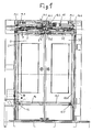
- the sliding door shown in Figs. 1 to 3 has two against each other movable door leaves 1 and 1A, which are inside a door portal 2 are arranged.
- the door panel 1 is in a manner not shown on a parallelogram linkage with a trained example as a ball sleeve or roller carriage Support member 8 is connected, which runs on a guide element 3, as a round rod or guide rail can be formed and fixed to the door portal 2 is connected.
- the door leaves 1 and 1A move in Direction of the guide elements 3 and 3A in opposite directions. Because it is a sliding door, is the longitudinal movement of the door leaf 1 with the transverse movement through a fixedly connected to the door portal 2 guide rail 5 coordinates, in which a connected to the door leaf, not illustrated guide means engages.
- the movement of the door leaves takes place by a drive motor 6, which may be designed as an electric motor and the output force via a revolving cam belt 7 on the door leaves is transmitted.
- the swinging of the door leaves by the transverse movement is supported, by the reaction force of the drive motor 6 via a coupling element 4 as well a trained as a pivot lever 4.1 transmission element and a Coupling rod 15 and a pivot lever, not shown, on a rotary column 10 is transmitted, which is rotatable in the vertical direction on the door portal. 2 is stored.
- On the rotary column 10 is an unillustrated upper roller lever and a lower roller lever 12 is arranged.
- the support roller of the upper roller lever runs in a not shown, arranged on the inside of the door panel 1 upper guide rail, while the guide rollers of the lower Roller lever 12 guided in a arranged on the door leaf guide rail 14 are.
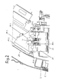
- the entire arranged in the upper region of the door portal 2 drive means AE is connected via fastening devices with the door portal 2. These fastening devices will be described in more detail below.
- Each fastening device 18.1, 18.2, 18.3 and 18.4 has one each Mounting plate 19.1, 19.2, and 19.4, which is connected to one of the door portal 2 Part 2.1 of the vehicle is fixed and on the other Parts of the fastening device are arranged.
- the fastening device 18.2 has a on the mounting plate 19.2 in a plane transverse to the door portal 2 lying first support plate 19.3, at the one fixed to an element 21 of the drive device AE and parallel to the first support plate 19.3 lying second support plate 20 in vertical direction and with respect to the angle adjustment by a horizontal Axle is mounted adjustable.
- Threaded bolts 22.1 and 22.2 pass through the support plates 19.3 and 20 in through holes that extended one opposite the threaded bolts Have diameter or formed as slots.
- Threaded bolts 22.1 and 22.2 pass through the support plates 19.3 and 20 in through holes that extended one opposite the threaded bolts Have diameter or formed as slots.
- a third vertically and parallel to the plane of the first support plate 19.3 lying threaded bolt 22.3 are two substantially horizontally extending and parallel to each other superimposed mounting pieces 19.31 and 20.1 interconnected, of which the first attachment piece 19.31 is firmly connected to the support plate 19.3 and the Support plate 20 penetrated in a recess 20.4 and of which the second attachment piece 20.1 at the of the support plate 19.3. facing away Side is secured below the recess 20.4 and below the first attachment piece 19.31 is arranged.
- the through hole in the first attachment piece 19.31 for receiving the third threaded bolt 22.3 has a larger diameter than the third threaded bolt 22.3.
- At the Top of the first attachment piece 19.31 is between this and the Head or the nut of the third threaded bolt 22.3 surrounding a bore annular, upwardly concave ball socket 24 arranged in the a downwardly convex, the threaded bolt 22.3 surrounding annular Ball disc 23 engages.
Landscapes
- Engineering & Computer Science (AREA)
- Mechanical Engineering (AREA)
- Power-Operated Mechanisms For Wings (AREA)
- Wing Frames And Configurations (AREA)
- Support Devices For Sliding Doors (AREA)
- Lock And Its Accessories (AREA)
- Lubricants (AREA)
Abstract
Description
- Fig. 1
- in einer aus dem Fahrzeuginneren gesehenen Gesamtansicht eine zweiflügelige Schwenkschiebetür in einer in der Höhe verkürzten Darstellung;
- Fig. 2
- einen Schnitt nach der Linie D-D in Fig. 1 in vergrößerter Darstellung;
- Fig. 3
- in gegenüber Fig. 1 vergrößerter Darstellung die Antriebseinrichtung der Schwenkschiebetür nach Fig. 1.
Claims (6)
- Schiebetür oder Schwenkschiebetür für Fahrzeuge des öffentlichen Personennah- und -fernverkehrs mit mindestens einem Türblatt und einer im oberen Bereich des Türportals angeordneten Antriebseinrichtung, die über Befestigungsvorrichtungen mit dem Türportal verbunden ist und ein Führungselement aufweist, auf dem das Türblatt in seiner Längsrichtung verschiebbar ist, sowie einen Antriebsmotor, dessen Abtriebskraft am Türblatt in Richtung des Führungselements angreift, dadurch gekennzeichnet, dass jede Befestigungsvorrichtung (18.1, 18.2, 18.3, 18.4) für die Antriebseinrichtung eine erste fest mit dem Türportal (2) verbundene und in einer Ebene quer zum Türportal liegende Halterungsplatte (19.3) aufweist, an der eine mit einem Element (21) der Antriebseinrichtung fest verbundene und parallel zur ersten Halterungsplatte (19.3) liegende zweite Halterungsplatte (20) in vertikaler Richtung und bezüglich der Winkeleinstellung um eine horizontale Achse justierbar befestigt ist.
- Schiebetür oder Schwenkschiebetür nach Anspruch 1, dadurch gekennzeichnet, dass die Befestigung der zweiten Halterungsplatte (20) an der ersten Halterungsplatte (19.3) folgende Befestigungsmittel aufweist:a) Zwei horizontal und senkrecht zur Ebene der ersten Halterungsplatte (19.3) liegende Gewindebolzen (22.1, 22.2), die jeweils mindestens eine der beiden Halterungsplatten (19.3, 20) in Durchtrittslöchern durchgreifen, die einen gegenüber dem Gewindebolzen erweiterten Durchmesser aufweisen oder als Langlöcher ausgeführt sind;b) einen dritten vertikal und parallel zur Ebene der ersten Halterungsplatte (19.3) liegenden Gewindebolzen (22.3), durch welchen zwei im wesentlichen horizontal verlaufende und parallel zueinander übereinander angeordnete Befestigungsstücke (19.31, 20.1) miteinander verbunden sind, von denen ein erstes (19.31) mit der einen Halterungsplatte (19.3) fest verbunden ist und die andere Halterungsplatte (20) in einer Ausnehmung (20.4) durchsetzt, und ein zweites mit der jeweils anderen Halterungsplatte (20) fest verbunden ist.
- Schiebetür oder Schwenkschiebetür nach Anspruch 2, dadurch gekennzeichnet, dass die Ausnehmung (20.4) in der zweiten Halterungsplatte (20) angeordnet ist und das erste Befestigungsstück (19.31) mit der ersten Halterungsplatte (19.3) verbunden und durch die Ausnehmung (20.4) in der zweiten Halterungsplatte (20) hindurchgeführt ist und das zweite Befestigungsstück (20.1) an der zweiten Halterungsplatte (20) an der von der ersten Halterungsplatte abgewandten Seite unterhalb der Ausnehmung (20.4) befestigt ist und unterhalb des ersten Befestigungsstückes (19.31) angeordnet ist.
- Schiebetür oder Schwenkschiebetür nach Anspruch 3, dadurch gekennzeichnet, dass die Durchgangsbohrung im ersten Befestigungsstück (19.31) zur Aufnahme des dritten Gewindebolzens (22.3) einen größeren Durchmesser besitzt als der dritte Gewindebolzen (22.3).
- Schiebetür oder Schwenkschiebetür nach Anspruch 4, dadurch gekennzeichnet, dass an der Oberseite des ersten Befestigungsstückes (19.31) zwischen diesem und dem Kopf bzw. der Mutter des dritten Gewindebolzens (22.3) eine die Bohrung umgebende ringförmige, nach oben konkave Kugelpfanne (24) angeordnet ist, in die eine nach unten konvexe, den Gewindebolzen (22.3) umgebende ringförmige Kugelscheibe (23) eingreift.
- Schiebetür oder Schwenkschiebetür nach Anspruch 2 und ggf. einem der Ansprüche 3 bis 5, dadurch gekennzeichnet, dass zum Durchtritt des ersten und zweiten Gewindebolzens (22.1,22.2) durch die erste Halterungsplatte (19.3) auf einem gemeinsamen Kreisbogen liegende bogenförmige Langlöcher in der ersten Halterungsplatte (19.3) angeordnet sind.
Priority Applications (1)
| Application Number | Priority Date | Filing Date | Title |
|---|---|---|---|
| PL05002071T PL1577134T3 (pl) | 2004-02-25 | 2005-02-02 | Drzwi przesuwne lub obrotowo-przesuwne do pojazdów publicznej lokalnej i dalekobieżnej komunikacji pasażerskiej |
Applications Claiming Priority (2)
| Application Number | Priority Date | Filing Date | Title |
|---|---|---|---|
| DE202004002907U | 2004-02-25 | ||
| DE202004002907U DE202004002907U1 (de) | 2004-02-25 | 2004-02-25 | Schiebetür oder Schwenkschiebetür für Fahrzeuge des öffentlichen Personennah- und -fernverkehrs |
Publications (3)
| Publication Number | Publication Date |
|---|---|
| EP1577134A2 true EP1577134A2 (de) | 2005-09-21 |
| EP1577134A3 EP1577134A3 (de) | 2009-09-09 |
| EP1577134B1 EP1577134B1 (de) | 2011-04-20 |
Family
ID=32309208
Family Applications (1)
| Application Number | Title | Priority Date | Filing Date |
|---|---|---|---|
| EP05002071A Expired - Lifetime EP1577134B1 (de) | 2004-02-25 | 2005-02-02 | Schiebetür oder Schwenkschiebetür für Fahrzeuge des öffentlichen Personennah- und -fernferkehrs |
Country Status (5)
| Country | Link |
|---|---|
| EP (1) | EP1577134B1 (de) |
| AT (1) | ATE506211T1 (de) |
| DE (2) | DE202004002907U1 (de) |
| ES (1) | ES2364847T3 (de) |
| PL (1) | PL1577134T3 (de) |
Cited By (2)
| Publication number | Priority date | Publication date | Assignee | Title |
|---|---|---|---|---|
| CN102852421A (zh) * | 2012-08-21 | 2013-01-02 | 南京康尼机电股份有限公司 | 客车车辆塞拉平移式开关门机构 |
| US10993777B2 (en) | 2015-03-27 | 2021-05-04 | Brainlab Robotics Gmbh | Method and apparatus for controlling a surgical mechatronic assistance system by means of a holding arm for medical purposes |
Family Cites Families (6)
| Publication number | Priority date | Publication date | Assignee | Title |
|---|---|---|---|---|
| GB652710A (en) * | 1948-04-26 | 1951-05-02 | Nat Pneumatic Co | Improvements in vehicle door operating mechanisms |
| GB814297A (en) * | 1955-01-21 | 1959-06-03 | Karl Sagl | Sliding door, particularly for vehicles |
| DE8226126U1 (de) * | 1982-09-16 | 1982-11-18 | Kiekert GmbH & Co KG, 5628 Heiligenhaus | Aussenlaufende doppelschiebetuer fuer fahrzeuge |
| IT1184012B (it) * | 1985-12-11 | 1987-10-22 | Wabco Westinghouse Spa | Porta per veicolo particolarmente veicoli ferroviari e di metropolitane |
| US6446389B1 (en) * | 2000-04-14 | 2002-09-10 | Westinghouse Air Brake Technologies Corporation | Tandem sliding door operator |
| DE10158094A1 (de) * | 2001-11-27 | 2003-07-24 | Bode Gmbh & Co Kg | Schwenkschiebetür für Fahrzeuge, insbesondere Fahrgasttür für Fahrzeuge des öffentlichen Personennahverkehrs |
-
2004
- 2004-02-25 DE DE202004002907U patent/DE202004002907U1/de not_active Expired - Lifetime
-
2005
- 2005-02-02 PL PL05002071T patent/PL1577134T3/pl unknown
- 2005-02-02 EP EP05002071A patent/EP1577134B1/de not_active Expired - Lifetime
- 2005-02-02 DE DE502005011262T patent/DE502005011262D1/de not_active Expired - Lifetime
- 2005-02-02 ES ES05002071T patent/ES2364847T3/es not_active Expired - Lifetime
- 2005-02-02 AT AT05002071T patent/ATE506211T1/de active
Cited By (2)
| Publication number | Priority date | Publication date | Assignee | Title |
|---|---|---|---|---|
| CN102852421A (zh) * | 2012-08-21 | 2013-01-02 | 南京康尼机电股份有限公司 | 客车车辆塞拉平移式开关门机构 |
| US10993777B2 (en) | 2015-03-27 | 2021-05-04 | Brainlab Robotics Gmbh | Method and apparatus for controlling a surgical mechatronic assistance system by means of a holding arm for medical purposes |
Also Published As
| Publication number | Publication date |
|---|---|
| DE502005011262D1 (de) | 2011-06-01 |
| PL1577134T3 (pl) | 2011-09-30 |
| ES2364847T3 (es) | 2011-09-15 |
| EP1577134B1 (de) | 2011-04-20 |
| EP1577134A3 (de) | 2009-09-09 |
| DE202004002907U1 (de) | 2004-05-06 |
| ATE506211T1 (de) | 2011-05-15 |
Similar Documents
| Publication | Publication Date | Title |
|---|---|---|
| EP0704595A1 (de) | Einstellvorrichtung für eine mit einer Fensterheberanordnung zusammenwirkende, rahmenlos ausgebildete Türfensterscheibe eines Kraftfahrzeuges | |
| EP1641992A1 (de) | F hrungseinrichtung f r eine schiebet r | |
| DE2633969A1 (de) | Montageeinrichtung fuer fensterscheibe eines automobilfensters | |
| DE102006012176A1 (de) | Einstellbarer Fensterheber I | |
| DE19956756C2 (de) | Einstellbarer Mitnehmer für einen Fensterheber einer rahmenlosen Fahrzeugtür | |
| DE2915389C2 (de) | Seilfensterheber für Kraftfahrzeuge | |
| DE60309028T2 (de) | Verbesserte vorrichtung zur seiteneinstellung von fensterhebern für kraftfahrzeuge und dergleichen | |
| DE202010001159U1 (de) | Mitnehmer für eine Verstellvorrichtung zum Verstellen eines Fahrzeugteils | |
| EP2995502B1 (de) | Dachträgeranordnung für ein kraftfahrzeug | |
| EP1577134B1 (de) | Schiebetür oder Schwenkschiebetür für Fahrzeuge des öffentlichen Personennah- und -fernferkehrs | |
| DE102005040459B4 (de) | Mitnehmer für Fensterheber von Fahrzeugen | |
| EP1563156A1 (de) | Vorrichtung und verfahren zum einstellen eines deckels einer kraftwagenkarosserie | |
| DE102004027253B4 (de) | Einrichtung zum Einstellen der Lage einer Führungsschiene für eine verstellbare Fensterscheibe eines Fahrzeuges | |
| EP3471982B1 (de) | Dreipunktlagerung einer schiebetür | |
| EP3472493B1 (de) | Vorrichtung zur kraftübertragung | |
| DE102004048924C5 (de) | Vorrichtung zum Heben und Senken einer Fensterscheibe | |
| DE202006002455U1 (de) | Schwenktritt für eine Türanordnung an einem Fahrzeug des öffentlichen Personennahverkehrs | |
| DE10332507A1 (de) | Elastisches Aggregatelager, insbesondere Motorgetriebelager in einem Kraftfahrzeug | |
| EP3095937A1 (de) | Anbindung für ein ortsveränderbares torblatt | |
| EP3850175B1 (de) | Einrichtung zur justierung eines türantriebs | |
| DE19963555B4 (de) | Armfensterheber | |
| DE102019109408B4 (de) | Zentriervorrichtung, die eine zumindest einachsige Zentrierung einer Schlossvorrichtung einer Heckklappe eines Fahrzeugs gewährleistet, Schlossvorrichtung mit einer solchen Zentriervorrichtung und Verfahren zur Zentrierung einer Heckklappe | |
| EP1791679B1 (de) | Bausatz zum modulartigen aufbau einer konsole | |
| DE102006020108A1 (de) | Hubfenster | |
| DE10244048B4 (de) | Vorrichtung zum Ausrichten einer Fahrzeugtür, insbesondere einer Kraftfahrzeugtür |
Legal Events
| Date | Code | Title | Description |
|---|---|---|---|
| PUAI | Public reference made under article 153(3) epc to a published international application that has entered the european phase |
Free format text: ORIGINAL CODE: 0009012 |
|
| AK | Designated contracting states |
Kind code of ref document: A2 Designated state(s): AT BE BG CH CY CZ DE DK EE ES FI FR GB GR HU IE IS IT LI LT LU MC NL PL PT RO SE SI SK TR |
|
| AX | Request for extension of the european patent |
Extension state: AL BA HR LV MK YU |
|
| RTI1 | Title (correction) |
Free format text: SLIDING DOOR OR SWINGING-SLIDING DOOR FOR VEHICLES OF THE URBAN AND LONG DISTANCE PASENGER TRAFFIC |
|
| PUAL | Search report despatched |
Free format text: ORIGINAL CODE: 0009013 |
|
| AK | Designated contracting states |
Kind code of ref document: A3 Designated state(s): AT BE BG CH CY CZ DE DK EE ES FI FR GB GR HU IE IS IT LI LT LU MC NL PL PT RO SE SI SK TR |
|
| AX | Request for extension of the european patent |
Extension state: AL BA HR LV MK YU |
|
| RIC1 | Information provided on ipc code assigned before grant |
Ipc: B60J 5/06 20060101AFI20050721BHEP Ipc: B60R 16/02 20060101ALI20090731BHEP |
|
| 17P | Request for examination filed |
Effective date: 20100212 |
|
| AKX | Designation fees paid |
Designated state(s): AT BE BG CH CY CZ DE DK EE ES FI FR GB GR HU IE IS IT LI LT LU MC NL PL PT RO SE SI SK TR |
|
| GRAP | Despatch of communication of intention to grant a patent |
Free format text: ORIGINAL CODE: EPIDOSNIGR1 |
|
| GRAS | Grant fee paid |
Free format text: ORIGINAL CODE: EPIDOSNIGR3 |
|
| GRAA | (expected) grant |
Free format text: ORIGINAL CODE: 0009210 |
|
| AK | Designated contracting states |
Kind code of ref document: B1 Designated state(s): AT BE BG CH CY CZ DE DK EE ES FI FR GB GR HU IE IS IT LI LT LU MC NL PL PT RO SE SI SK TR |
|
| REG | Reference to a national code |
Ref country code: GB Ref legal event code: FG4D Free format text: NOT ENGLISH |
|
| REG | Reference to a national code |
Ref country code: CH Ref legal event code: EP |
|
| REG | Reference to a national code |
Ref country code: IE Ref legal event code: FG4D Free format text: LANGUAGE OF EP DOCUMENT: GERMAN |
|
| REF | Corresponds to: |
Ref document number: 502005011262 Country of ref document: DE Date of ref document: 20110601 Kind code of ref document: P |
|
| REG | Reference to a national code |
Ref country code: DE Ref legal event code: R096 Ref document number: 502005011262 Country of ref document: DE Effective date: 20110601 |
|
| REG | Reference to a national code |
Ref country code: NL Ref legal event code: T3 |
|
| REG | Reference to a national code |
Ref country code: ES Ref legal event code: FG2A Ref document number: 2364847 Country of ref document: ES Kind code of ref document: T3 Effective date: 20110915 |
|
| LTIE | Lt: invalidation of european patent or patent extension |
Effective date: 20110420 |
|
| REG | Reference to a national code |
Ref country code: PL Ref legal event code: T3 |
|
| PG25 | Lapsed in a contracting state [announced via postgrant information from national office to epo] |
Ref country code: PT Free format text: LAPSE BECAUSE OF FAILURE TO SUBMIT A TRANSLATION OF THE DESCRIPTION OR TO PAY THE FEE WITHIN THE PRESCRIBED TIME-LIMIT Effective date: 20110822 Ref country code: LT Free format text: LAPSE BECAUSE OF FAILURE TO SUBMIT A TRANSLATION OF THE DESCRIPTION OR TO PAY THE FEE WITHIN THE PRESCRIBED TIME-LIMIT Effective date: 20110420 Ref country code: SE Free format text: LAPSE BECAUSE OF FAILURE TO SUBMIT A TRANSLATION OF THE DESCRIPTION OR TO PAY THE FEE WITHIN THE PRESCRIBED TIME-LIMIT Effective date: 20110420 |
|
| REG | Reference to a national code |
Ref country code: IE Ref legal event code: FD4D |
|
| PG25 | Lapsed in a contracting state [announced via postgrant information from national office to epo] |
Ref country code: SI Free format text: LAPSE BECAUSE OF FAILURE TO SUBMIT A TRANSLATION OF THE DESCRIPTION OR TO PAY THE FEE WITHIN THE PRESCRIBED TIME-LIMIT Effective date: 20110420 Ref country code: FI Free format text: LAPSE BECAUSE OF FAILURE TO SUBMIT A TRANSLATION OF THE DESCRIPTION OR TO PAY THE FEE WITHIN THE PRESCRIBED TIME-LIMIT Effective date: 20110420 Ref country code: IS Free format text: LAPSE BECAUSE OF FAILURE TO SUBMIT A TRANSLATION OF THE DESCRIPTION OR TO PAY THE FEE WITHIN THE PRESCRIBED TIME-LIMIT Effective date: 20110820 Ref country code: CY Free format text: LAPSE BECAUSE OF FAILURE TO SUBMIT A TRANSLATION OF THE DESCRIPTION OR TO PAY THE FEE WITHIN THE PRESCRIBED TIME-LIMIT Effective date: 20110420 Ref country code: GR Free format text: LAPSE BECAUSE OF FAILURE TO SUBMIT A TRANSLATION OF THE DESCRIPTION OR TO PAY THE FEE WITHIN THE PRESCRIBED TIME-LIMIT Effective date: 20110721 |
|
| PG25 | Lapsed in a contracting state [announced via postgrant information from national office to epo] |
Ref country code: EE Free format text: LAPSE BECAUSE OF FAILURE TO SUBMIT A TRANSLATION OF THE DESCRIPTION OR TO PAY THE FEE WITHIN THE PRESCRIBED TIME-LIMIT Effective date: 20110420 Ref country code: IE Free format text: LAPSE BECAUSE OF FAILURE TO SUBMIT A TRANSLATION OF THE DESCRIPTION OR TO PAY THE FEE WITHIN THE PRESCRIBED TIME-LIMIT Effective date: 20110420 |
|
| PLBE | No opposition filed within time limit |
Free format text: ORIGINAL CODE: 0009261 |
|
| STAA | Information on the status of an ep patent application or granted ep patent |
Free format text: STATUS: NO OPPOSITION FILED WITHIN TIME LIMIT |
|
| PG25 | Lapsed in a contracting state [announced via postgrant information from national office to epo] |
Ref country code: RO Free format text: LAPSE BECAUSE OF FAILURE TO SUBMIT A TRANSLATION OF THE DESCRIPTION OR TO PAY THE FEE WITHIN THE PRESCRIBED TIME-LIMIT Effective date: 20110420 Ref country code: SK Free format text: LAPSE BECAUSE OF FAILURE TO SUBMIT A TRANSLATION OF THE DESCRIPTION OR TO PAY THE FEE WITHIN THE PRESCRIBED TIME-LIMIT Effective date: 20110420 Ref country code: DK Free format text: LAPSE BECAUSE OF FAILURE TO SUBMIT A TRANSLATION OF THE DESCRIPTION OR TO PAY THE FEE WITHIN THE PRESCRIBED TIME-LIMIT Effective date: 20110420 |
|
| 26N | No opposition filed |
Effective date: 20120123 |
|
| REG | Reference to a national code |
Ref country code: DE Ref legal event code: R097 Ref document number: 502005011262 Country of ref document: DE Effective date: 20120123 |
|
| BERE | Be: lapsed |
Owner name: GEBR. BODE G.M.B.H. & CO. KG Effective date: 20120228 |
|
| PG25 | Lapsed in a contracting state [announced via postgrant information from national office to epo] |
Ref country code: MC Free format text: LAPSE BECAUSE OF NON-PAYMENT OF DUE FEES Effective date: 20120229 |
|
| PG25 | Lapsed in a contracting state [announced via postgrant information from national office to epo] |
Ref country code: BE Free format text: LAPSE BECAUSE OF NON-PAYMENT OF DUE FEES Effective date: 20120228 |
|
| PG25 | Lapsed in a contracting state [announced via postgrant information from national office to epo] |
Ref country code: BG Free format text: LAPSE BECAUSE OF FAILURE TO SUBMIT A TRANSLATION OF THE DESCRIPTION OR TO PAY THE FEE WITHIN THE PRESCRIBED TIME-LIMIT Effective date: 20110720 |
|
| PG25 | Lapsed in a contracting state [announced via postgrant information from national office to epo] |
Ref country code: LU Free format text: LAPSE BECAUSE OF NON-PAYMENT OF DUE FEES Effective date: 20120202 |
|
| PG25 | Lapsed in a contracting state [announced via postgrant information from national office to epo] |
Ref country code: HU Free format text: LAPSE BECAUSE OF FAILURE TO SUBMIT A TRANSLATION OF THE DESCRIPTION OR TO PAY THE FEE WITHIN THE PRESCRIBED TIME-LIMIT Effective date: 20050202 |
|
| REG | Reference to a national code |
Ref country code: FR Ref legal event code: PLFP Year of fee payment: 12 |
|
| REG | Reference to a national code |
Ref country code: FR Ref legal event code: PLFP Year of fee payment: 13 |
|
| PGFP | Annual fee paid to national office [announced via postgrant information from national office to epo] |
Ref country code: DE Payment date: 20170222 Year of fee payment: 13 Ref country code: FR Payment date: 20170220 Year of fee payment: 13 Ref country code: CH Payment date: 20170221 Year of fee payment: 13 |
|
| PGFP | Annual fee paid to national office [announced via postgrant information from national office to epo] |
Ref country code: NL Payment date: 20170220 Year of fee payment: 13 Ref country code: AT Payment date: 20170217 Year of fee payment: 13 Ref country code: PL Payment date: 20170127 Year of fee payment: 13 Ref country code: CZ Payment date: 20170202 Year of fee payment: 13 Ref country code: GB Payment date: 20170221 Year of fee payment: 13 |
|
| PGFP | Annual fee paid to national office [announced via postgrant information from national office to epo] |
Ref country code: IT Payment date: 20170217 Year of fee payment: 13 Ref country code: ES Payment date: 20170220 Year of fee payment: 13 Ref country code: TR Payment date: 20170201 Year of fee payment: 13 |
|
| REG | Reference to a national code |
Ref country code: DE Ref legal event code: R119 Ref document number: 502005011262 Country of ref document: DE |
|
| REG | Reference to a national code |
Ref country code: CH Ref legal event code: PL |
|
| REG | Reference to a national code |
Ref country code: NL Ref legal event code: MM Effective date: 20180301 |
|
| REG | Reference to a national code |
Ref country code: AT Ref legal event code: MM01 Ref document number: 506211 Country of ref document: AT Kind code of ref document: T Effective date: 20180202 |
|
| GBPC | Gb: european patent ceased through non-payment of renewal fee |
Effective date: 20180202 |
|
| PG25 | Lapsed in a contracting state [announced via postgrant information from national office to epo] |
Ref country code: AT Free format text: LAPSE BECAUSE OF NON-PAYMENT OF DUE FEES Effective date: 20180202 Ref country code: CH Free format text: LAPSE BECAUSE OF NON-PAYMENT OF DUE FEES Effective date: 20180228 Ref country code: LI Free format text: LAPSE BECAUSE OF NON-PAYMENT OF DUE FEES Effective date: 20180228 Ref country code: CZ Free format text: LAPSE BECAUSE OF NON-PAYMENT OF DUE FEES Effective date: 20180202 |
|
| REG | Reference to a national code |
Ref country code: FR Ref legal event code: ST Effective date: 20181031 |
|
| PG25 | Lapsed in a contracting state [announced via postgrant information from national office to epo] |
Ref country code: NL Free format text: LAPSE BECAUSE OF NON-PAYMENT OF DUE FEES Effective date: 20180301 |
|
| PG25 | Lapsed in a contracting state [announced via postgrant information from national office to epo] |
Ref country code: DE Free format text: LAPSE BECAUSE OF NON-PAYMENT OF DUE FEES Effective date: 20180901 |
|
| PG25 | Lapsed in a contracting state [announced via postgrant information from national office to epo] |
Ref country code: IT Free format text: LAPSE BECAUSE OF NON-PAYMENT OF DUE FEES Effective date: 20180202 Ref country code: GB Free format text: LAPSE BECAUSE OF NON-PAYMENT OF DUE FEES Effective date: 20180202 Ref country code: FR Free format text: LAPSE BECAUSE OF NON-PAYMENT OF DUE FEES Effective date: 20180228 |
|
| PG25 | Lapsed in a contracting state [announced via postgrant information from national office to epo] |
Ref country code: PL Free format text: LAPSE BECAUSE OF NON-PAYMENT OF DUE FEES Effective date: 20180202 |
|
| REG | Reference to a national code |
Ref country code: ES Ref legal event code: FD2A Effective date: 20190801 |
|
| PG25 | Lapsed in a contracting state [announced via postgrant information from national office to epo] |
Ref country code: ES Free format text: LAPSE BECAUSE OF NON-PAYMENT OF DUE FEES Effective date: 20180203 |
|
| PG25 | Lapsed in a contracting state [announced via postgrant information from national office to epo] |
Ref country code: TR Free format text: LAPSE BECAUSE OF NON-PAYMENT OF DUE FEES Effective date: 20180202 |