EP1577134B1 - Schiebetür oder Schwenkschiebetür für Fahrzeuge des öffentlichen Personennah- und -fernferkehrs - Google Patents
Schiebetür oder Schwenkschiebetür für Fahrzeuge des öffentlichen Personennah- und -fernferkehrs Download PDFInfo
- Publication number
- EP1577134B1 EP1577134B1 EP05002071A EP05002071A EP1577134B1 EP 1577134 B1 EP1577134 B1 EP 1577134B1 EP 05002071 A EP05002071 A EP 05002071A EP 05002071 A EP05002071 A EP 05002071A EP 1577134 B1 EP1577134 B1 EP 1577134B1
- Authority
- EP
- European Patent Office
- Prior art keywords
- holding plate
- door
- sliding
- sliding door
- threaded bolt
- Prior art date
- Legal status (The legal status is an assumption and is not a legal conclusion. Google has not performed a legal analysis and makes no representation as to the accuracy of the status listed.)
- Expired - Lifetime
Links
- 230000008878 coupling Effects 0.000 description 2
- 238000010168 coupling process Methods 0.000 description 2
- 238000005859 coupling reaction Methods 0.000 description 2
- 230000005540 biological transmission Effects 0.000 description 1
- 238000006243 chemical reaction Methods 0.000 description 1
- 230000001419 dependent effect Effects 0.000 description 1
- 238000011161 development Methods 0.000 description 1
- 230000018109 developmental process Effects 0.000 description 1
- 238000006073 displacement reaction Methods 0.000 description 1
Images
Classifications
-
- B—PERFORMING OPERATIONS; TRANSPORTING
- B60—VEHICLES IN GENERAL
- B60J—WINDOWS, WINDSCREENS, NON-FIXED ROOFS, DOORS, OR SIMILAR DEVICES FOR VEHICLES; REMOVABLE EXTERNAL PROTECTIVE COVERINGS SPECIALLY ADAPTED FOR VEHICLES
- B60J5/00—Doors
- B60J5/04—Doors arranged at the vehicle sides
- B60J5/06—Doors arranged at the vehicle sides slidable; foldable
- B60J5/062—Doors arranged at the vehicle sides slidable; foldable for utility vehicles or public transport
-
- B—PERFORMING OPERATIONS; TRANSPORTING
- B61—RAILWAYS
- B61D—BODY DETAILS OR KINDS OF RAILWAY VEHICLES
- B61D19/00—Door arrangements specially adapted for rail vehicles
- B61D19/02—Door arrangements specially adapted for rail vehicles for carriages
-
- E—FIXED CONSTRUCTIONS
- E05—LOCKS; KEYS; WINDOW OR DOOR FITTINGS; SAFES
- E05D—HINGES OR SUSPENSION DEVICES FOR DOORS, WINDOWS OR WINGS
- E05D15/00—Suspension arrangements for wings
- E05D15/06—Suspension arrangements for wings for wings sliding horizontally more or less in their own plane
- E05D15/10—Suspension arrangements for wings for wings sliding horizontally more or less in their own plane movable out of one plane into a second parallel plane
- E05D2015/1028—Suspension arrangements for wings for wings sliding horizontally more or less in their own plane movable out of one plane into a second parallel plane with only the wing moving transversely
- E05D2015/1031—Suspension arrangements for wings for wings sliding horizontally more or less in their own plane movable out of one plane into a second parallel plane with only the wing moving transversely the wing supported on arms extending from the carriage
- E05D2015/1034—Suspension arrangements for wings for wings sliding horizontally more or less in their own plane movable out of one plane into a second parallel plane with only the wing moving transversely the wing supported on arms extending from the carriage the carriage having means for preventing rotation of the wing
-
- E—FIXED CONSTRUCTIONS
- E05—LOCKS; KEYS; WINDOW OR DOOR FITTINGS; SAFES
- E05D—HINGES OR SUSPENSION DEVICES FOR DOORS, WINDOWS OR WINGS
- E05D15/00—Suspension arrangements for wings
- E05D15/06—Suspension arrangements for wings for wings sliding horizontally more or less in their own plane
- E05D15/10—Suspension arrangements for wings for wings sliding horizontally more or less in their own plane movable out of one plane into a second parallel plane
- E05D15/1065—Suspension arrangements for wings for wings sliding horizontally more or less in their own plane movable out of one plane into a second parallel plane with transversely moving track
- E05D2015/1084—Suspension arrangements for wings for wings sliding horizontally more or less in their own plane movable out of one plane into a second parallel plane with transversely moving track the carriage being directly linked to the fixed frame, e.g. slidingly
- E05D2015/1086—Suspension arrangements for wings for wings sliding horizontally more or less in their own plane movable out of one plane into a second parallel plane with transversely moving track the carriage being directly linked to the fixed frame, e.g. slidingly swingingly, e.g. on arms
-
- E—FIXED CONSTRUCTIONS
- E05—LOCKS; KEYS; WINDOW OR DOOR FITTINGS; SAFES
- E05F—DEVICES FOR MOVING WINGS INTO OPEN OR CLOSED POSITION; CHECKS FOR WINGS; WING FITTINGS NOT OTHERWISE PROVIDED FOR, CONCERNED WITH THE FUNCTIONING OF THE WING
- E05F15/00—Power-operated mechanisms for wings
- E05F15/60—Power-operated mechanisms for wings using electrical actuators
- E05F15/603—Power-operated mechanisms for wings using electrical actuators using rotary electromotors
- E05F15/611—Power-operated mechanisms for wings using electrical actuators using rotary electromotors for swinging wings
- E05F15/63—Power-operated mechanisms for wings using electrical actuators using rotary electromotors for swinging wings operated by swinging arms
-
- E—FIXED CONSTRUCTIONS
- E05—LOCKS; KEYS; WINDOW OR DOOR FITTINGS; SAFES
- E05F—DEVICES FOR MOVING WINGS INTO OPEN OR CLOSED POSITION; CHECKS FOR WINGS; WING FITTINGS NOT OTHERWISE PROVIDED FOR, CONCERNED WITH THE FUNCTIONING OF THE WING
- E05F15/00—Power-operated mechanisms for wings
- E05F15/60—Power-operated mechanisms for wings using electrical actuators
- E05F15/603—Power-operated mechanisms for wings using electrical actuators using rotary electromotors
- E05F15/632—Power-operated mechanisms for wings using electrical actuators using rotary electromotors for horizontally-sliding wings
- E05F15/655—Power-operated mechanisms for wings using electrical actuators using rotary electromotors for horizontally-sliding wings specially adapted for vehicle wings
-
- E—FIXED CONSTRUCTIONS
- E05—LOCKS; KEYS; WINDOW OR DOOR FITTINGS; SAFES
- E05F—DEVICES FOR MOVING WINGS INTO OPEN OR CLOSED POSITION; CHECKS FOR WINGS; WING FITTINGS NOT OTHERWISE PROVIDED FOR, CONCERNED WITH THE FUNCTIONING OF THE WING
- E05F17/00—Special devices for shifting a plurality of wings operated simultaneously
- E05F17/004—Special devices for shifting a plurality of wings operated simultaneously for wings which abut when closed
-
- E—FIXED CONSTRUCTIONS
- E05—LOCKS; KEYS; WINDOW OR DOOR FITTINGS; SAFES
- E05Y—INDEXING SCHEME ASSOCIATED WITH SUBCLASSES E05D AND E05F, RELATING TO CONSTRUCTION ELEMENTS, ELECTRIC CONTROL, POWER SUPPLY, POWER SIGNAL OR TRANSMISSION, USER INTERFACES, MOUNTING OR COUPLING, DETAILS, ACCESSORIES, AUXILIARY OPERATIONS NOT OTHERWISE PROVIDED FOR, APPLICATION THEREOF
- E05Y2201/00—Constructional elements; Accessories therefor
- E05Y2201/40—Motors; Magnets; Springs; Weights; Accessories therefor
- E05Y2201/43—Motors
- E05Y2201/434—Electromotors; Details thereof
-
- E—FIXED CONSTRUCTIONS
- E05—LOCKS; KEYS; WINDOW OR DOOR FITTINGS; SAFES
- E05Y—INDEXING SCHEME ASSOCIATED WITH SUBCLASSES E05D AND E05F, RELATING TO CONSTRUCTION ELEMENTS, ELECTRIC CONTROL, POWER SUPPLY, POWER SIGNAL OR TRANSMISSION, USER INTERFACES, MOUNTING OR COUPLING, DETAILS, ACCESSORIES, AUXILIARY OPERATIONS NOT OTHERWISE PROVIDED FOR, APPLICATION THEREOF
- E05Y2600/00—Mounting or coupling arrangements for elements provided for in this subclass
- E05Y2600/10—Adjustable
- E05Y2600/11—Adjustable by automatically acting means
-
- E—FIXED CONSTRUCTIONS
- E05—LOCKS; KEYS; WINDOW OR DOOR FITTINGS; SAFES
- E05Y—INDEXING SCHEME ASSOCIATED WITH SUBCLASSES E05D AND E05F, RELATING TO CONSTRUCTION ELEMENTS, ELECTRIC CONTROL, POWER SUPPLY, POWER SIGNAL OR TRANSMISSION, USER INTERFACES, MOUNTING OR COUPLING, DETAILS, ACCESSORIES, AUXILIARY OPERATIONS NOT OTHERWISE PROVIDED FOR, APPLICATION THEREOF
- E05Y2600/00—Mounting or coupling arrangements for elements provided for in this subclass
- E05Y2600/10—Adjustable
- E05Y2600/30—Adjustment motion
- E05Y2600/32—Rotary motion
- E05Y2600/322—Rotary motion around a horizontal axis
-
- E—FIXED CONSTRUCTIONS
- E05—LOCKS; KEYS; WINDOW OR DOOR FITTINGS; SAFES
- E05Y—INDEXING SCHEME ASSOCIATED WITH SUBCLASSES E05D AND E05F, RELATING TO CONSTRUCTION ELEMENTS, ELECTRIC CONTROL, POWER SUPPLY, POWER SIGNAL OR TRANSMISSION, USER INTERFACES, MOUNTING OR COUPLING, DETAILS, ACCESSORIES, AUXILIARY OPERATIONS NOT OTHERWISE PROVIDED FOR, APPLICATION THEREOF
- E05Y2800/00—Details, accessories and auxiliary operations not otherwise provided for
- E05Y2800/73—Multiple functions
-
- E—FIXED CONSTRUCTIONS
- E05—LOCKS; KEYS; WINDOW OR DOOR FITTINGS; SAFES
- E05Y—INDEXING SCHEME ASSOCIATED WITH SUBCLASSES E05D AND E05F, RELATING TO CONSTRUCTION ELEMENTS, ELECTRIC CONTROL, POWER SUPPLY, POWER SIGNAL OR TRANSMISSION, USER INTERFACES, MOUNTING OR COUPLING, DETAILS, ACCESSORIES, AUXILIARY OPERATIONS NOT OTHERWISE PROVIDED FOR, APPLICATION THEREOF
- E05Y2900/00—Application of doors, windows, wings or fittings thereof
- E05Y2900/50—Application of doors, windows, wings or fittings thereof for vehicles
- E05Y2900/51—Application of doors, windows, wings or fittings thereof for vehicles for railway cars or mass transit vehicles
Definitions
- the invention relates to a sliding door or sliding door for vehicles of public passenger and long-distance traffic with the features of the preamble of claim 1.
- the invention has for its object to provide a sliding door or sliding door with the features specified in the preamble of claim 1, in which the assembly and adjustment of the drive means can be carried out quickly and precisely with simple means.
- the fastening of the drive means via a plurality of fastening devices each of which has two support plates, wherein a first support plate with the door frame and a second support plate with an element of the drive device connected is.
- the two support plates which are substantially parallel to each other in vertical planes, can be interconnected by three threaded bolts, two of which are horizontal and one is vertically aligned.
- the two support plates are formed and the threaded bolts arranged so that displacement and pivoting movements between the two support plates and thereby an adjustment of the entire drive device in height and in the angular position are possible.
- the in the Fig. 1 to 3 shown sliding door has two mutually movable door leaves 1 and 1A, which are arranged within a door portal 2.
- the corresponding individual parts, which are each associated with one of the two door leaves 1 and 1A, are designated by the same reference numerals, wherein the reference number of a door leaf at the second door leaf A is added.
- the door leaf 1 is connected in a manner not shown via a Parallelogrammgestfite with a trained example as a ball sleeve or roller carriage support member 8, which runs on a guide element 3, which may be formed as a round rod or guide rail and which is firmly connected to the door portal 2.
- a Parallelogrammgestfite with a trained example as a ball sleeve or roller carriage support member 8, which runs on a guide element 3, which may be formed as a round rod or guide rail and which is firmly connected to the door portal 2.
- the door leaves 1 and 1A move in the direction of the guide elements 3 and 3A in opposite directions. Since it is a sliding sliding door, the longitudinal movement of the door panel 1 with the transverse movement is coordinated by a fixedly connected to the door portal 2 guide rail 5, in which engages a connected to the door leaf, not shown guide means.
- the movement of the door leaves is effected by a drive motor 6, which may be designed as an electric motor and the output force is transmitted via a revolving cam belt 7 on the door leaves.
- the pivoting of the door leaves by the transverse movement is supported by the reaction force of the drive motor 6 is transmitted via a coupling element 4 and a trained as a pivot lever 4.1 transmission element and a coupling rod 15 and a pivoting lever, not shown on a rotary column 10 which rotates in the vertical direction on the door portal 2 is stored.
- a coupling element 4 and a trained as a pivot lever 4.1 transmission element and a coupling rod 15 and a pivoting lever, not shown on a rotary column 10 which rotates in the vertical direction on the door portal 2 is stored.
- an unillustrated upper roller lever and a lower roller lever 12 is arranged at the rotary column 10.
- the support roller of the upper roller lever runs in a not shown, arranged on the inside of the door leaf 1 upper guide rail, while the guide rollers of the lower roller lever 12 are guided in a arranged on the door leaf guide rail 14.
- the entire arranged in the upper region of the door portal 2 drive device AE is connected via fastening devices with the door portal 2. These fastening devices will be described in more detail below.
- Each fastening device 18.1, 18.2, 18.3 and 18.4 each have a mounting plate 19.1, 19.2, and 19.4, which is fixedly disposed on a connected to the door portal 2 Part 2.1 of the vehicle and on which the other parts of the fastening device are arranged.
- the fastening device 18.2 has a first mounting plate 19.3 lying on the mounting plate 19.2 in a plane transverse to the door portal 2, to which a second mounting plate 20 fixedly connected to an element 21 of the drive device AE and parallel to the first mounting plate 19.3 in the vertical direction and with respect to the angular adjustment attached adjustable about a horizontal axis.
- a third vertically and parallel to the plane of the first support plate 19.3 lying threaded bolt 22.3 two substantially horizontally extending and parallel to each other arranged mounting pieces 19.31 and 20.1 are interconnected, of which the first attachment piece 19.31 is firmly connected to the support plate 19.3 and the Support plate 20 penetrated in a recess 20.4 and of which the second attachment piece 20.1 on the of the support plate 19.3. opposite side is secured below the recess 20.4 and is arranged below the first attachment piece 19.31.
- the through hole in the first attachment piece 19.31 for receiving the third threaded bolt 22.3 has a larger diameter than the third threaded bolt 22.3.
- At the top of the first attachment piece 19.31 is between this and the head or the nut of the third threaded bolt 22.3 surrounding the bore an annular, upwardly concave ball socket 24, in which a downwardly convex, the threaded bolt 22.3 surrounding annular spherical disk 23 engages.
- arcuate elongated holes lying in a manner not shown on a common circular arc W are arranged.
Landscapes
- Engineering & Computer Science (AREA)
- Mechanical Engineering (AREA)
- Power-Operated Mechanisms For Wings (AREA)
- Wing Frames And Configurations (AREA)
- Support Devices For Sliding Doors (AREA)
- Lubricants (AREA)
- Lock And Its Accessories (AREA)
Description
- Die Erfindung betrifft eine Schiebetür oder Schwenkschiebetür für Fahrzeuge des öffentlichen Personennah- und -fernverkehrs mit den Merkmalen aus dem Oberbegriff des Patentanspruchs 1.
- Schwenkschiebetüren dieser Bauart sind grundsätzlich bekannt.
- Bei der Montage von Schwenkschiebetüren in dem Türportal eines Fahrzeugs tritt das Problem auf, dass die im oberen Bereich des Türportals angeordnete Antriebseinrichtung in Höhe und Winkelstellung sehr genau justiert werden muss, damit das Öffnen und Schließen der Schwenkschiebetür einwandfrei funktioniert.
- Der Erfindung liegt die Aufgabe zugrunde, eine Schiebetür oder Schwenkschiebetür mit den im Oberbegriff des Patentanspruchs 1 angegebenen Merkmalen zu schaffen, bei der die Montage und Justierung der Antriebseinrichtung rasch und präzise mit einfachen Mitteln durchführbar ist.
- Die Lösung dieser Aufgabe erfolgt erfindungsgemäß mit den Merkmalen aus dem kennzeichnenden Teil des Patentanspruchs 1. Vorteilhafte Weiterbildungen der Erfindung sind in den abhängigen Ansprüchen beschrieben.
- Der Grundgedanke der Erfindung besteht darin, die Antriebseinrichtung über Befestigungsvorrichtungen im Türportal aufzuhängen, welche eine einfach und rasche Justierung ermöglichen. Bei einer besonders vorteilhaften und in den Patentansprüchen 2 und folgenden beschriebenen Ausführungsform der erfindungsgemäßen Schiebetür oder Schwenkschiebetür erfolgt die Befestigung der Antriebseinrichtung über mehrere Befestigungsvorrichtungen, von denen jede zwei Halterungsplatten besitzt, wobei eine erste Halterungsplatte mit dem Türrahmen und eine zweite Halterungsplatte mit einem Element der Antriebseinrichtung verbunden ist. Die beiden Halterungsplatten, die im wesentlichen parallel zueinander in vertikalen Ebenen liegen, können über drei Gewindebolzen miteinander verbunden sein, von denen zwei horizontal verlaufen und einer vertikal ausgerichtet ist. Die beiden Halterungsplatten sind derart ausgebildet und die Gewindebolzen so angeordnet, dass Verschiebungs- und Schwenkbewegungen zwischen den beiden Halterungsplatten und dadurch eine Justierung der gesamten Antriebseinrichtung in der Höhe und in der Winkelstellung möglich sind.
- Im folgenden wird anhand der beigefügten Zeichnungen ein Ausführungsbeispiel für eine Schwenkschiebetür nach der Erfindung näher erläutert.
- In den Zeichnungen zeigen:
- Fig. 1
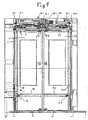
- in einer aus dem Fahrzeuginneren gesehenen Gesamtansicht eine zweiflügelige Schwenkschiebetür in einer in der Höhe verkürzten Darstellung;
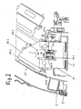
- Fig. 2
- einen Schnitt nach der Linie D-D in
Fig. 3 in vergrößerter Darstellung; - Fig. 3
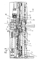
- in gegenüber
Fig. 1 vergrößerter Darstellung die Antriebseinrichtung der Schwenkschiebetür nachFig. 1 . - Die in den
Fig. 1 bis 3 dargestellte Schwenkschiebetür besitzt zwei gegeneinander bewegbare Türblätter 1 und 1A, die innerhalb eines Türportals 2 angeordnet sind. Im folgenden werden die einander entsprechenden Einzelteile, die jeweils einem der beiden Türblätter 1 und 1A zugeordnet sind, mit den gleichen Bezugsziffern bezeichnet, wobei der Bezugsziffer des einen Türblatts beim zweiten Türblatt ein A hinzugefügt wird. - Das Türblatt 1 ist in nicht dargestellter Weise über ein Parallelogrammgestänge mit einem beispielsweise als Kugelhülse oder Rollenschlitten ausgebildeten Tragglied 8 verbunden, das auf einem Führungselement 3 läuft, das als Rundstange oder Führungsschiene ausgebildet sein kann und das fest mit dem Türportal 2 verbunden ist.
- Beim Öffnen und Schließen der Tür bewegen sich die Türblätter 1 und 1A in Richtung der Führungselemente 3 und 3A in gegenläufiger Bewegung. Da es sich um eine Schwenkschiebetür handelt, ist die Längsbewegung des Türblatts 1 mit der Querbewegung durch eine mit dem Türportal 2 fest verbundene Führungsschiene 5 koordiniert, in welche ein mit dem Türblatt verbundenes, nicht dargestelltes Führungsmittel eingreift. Die Bewegung der Türblätter erfolgt durch einen Antriebsmotor 6, der als Elektromotor ausgebildet sein kann und dessen Abtriebskraft über einen umlaufenden Nockenriemen 7 auf die Türblätter übertragen wird.
- Das Ausschwenken der Türblätter durch die Querbewegung wird unterstützt, indem die Reaktionskraft des Antriebsmotors 6 über ein Koppelelement 4 sowie ein als Schwenkhebel 4.1 ausgebildetes Übertragungselement und eine Koppelstange 15 sowie einen nicht dargestellten Schwenkhebel auf eine Drehsäule 10 übertragen wird, die in vertikaler Richtung drehbar am Türportal 2 gelagert ist. An der Drehsäule 10 ist ein nicht dargestellter oberer Rollenhebel und ein unterer Rollenhebel 12 angeordnet. Die Stützrolle des oberen Rollenhebels läuft in einer nicht dargestellten, an der Innenseite des Türblatts 1 angeordneten oberen Führungsschiene, während die Führungsrollen des unteren Rollenhebels 12 in einer am Türblatt angeordneten Führungsschiene 14 geführt sind.
- Die gesamte im oberen Bereich des Türportals 2 angeordnete Antriebseinrichtung AE ist über Befestigungsvorrichtungen mit dem Türportal 2 verbunden. Diese Befestigungsvorrichtungen werden im folgenden näher beschrieben.
- Jede Befestigungsvorrichtung 18.1, 18.2, 18.3 und 18.4 besitzt jeweils eine Befestigungsplatte 19.1, 19.2, und 19.4, die an einem mit dem Türportal 2 verbundenen Teil 2.1 des Fahrzeugs fest angeordnet ist und an der die weiteren Teile der Befestigungsvorrichtung angeordnet sind.
- Da die in den
Fig. 1 und3 dargestellten Befestigungsvorrichtungen in gleicher Weise ausgebildet sind, erfolgt die weitere Beschreibung anhand der Befestigungsvorrichtung 18.2, die inFig. 2 undFig. 3 gut zu erkennen ist. - Die Befestigungsvorrichtung 18.2 besitzt eine an der Befestigungsplatte 19.2 in einer Ebene quer zum Türportal 2 liegende erste Halterungsplatte 19.3, an der eine mit einem Element 21 der Antriebseinrichtung AE fest verbundene und parallel zur ersten Halterungsplatte 19.3 liegende zweite Halterungsplatte 20 in vertikaler Richtung und bezüglich der Winkeleinstellung um eine horizontale Achse justierbar befestigt ist.
- Hierzu dienen die nachfolgend aufgeführten Befestigungsmittel.
- Zwei horizontal und senkrecht zur Ebene der ersten Halterungsplatte 19.3 liegende Gewindebolzen 22.1 und 22.2 durchgreifen die Halterungsplatten 19.3 und 20 in Durchtrittslöchern, die einen gegenüber den Gewindebolzen erweiterten Durchmesser aufweisen oder als Langlöcher ausgebildet sind. Durch einen dritten vertikal und parallel zur Ebene der ersten Halterungsplatte 19.3 liegenden Gewindebolzen 22.3 werden zwei im wesentlichen horizontal verlaufende und parallel zueinander übereinander angeordnete Befestigungsstücke 19.31 und 20.1 miteinander verbunden, von denen das erste Befestigungsstück 19.31 mit der Halterungsplatte 19.3 fest verbunden ist und die Halterungsplatte 20 in einer Ausnehmung 20.4 durchsetzt und von denen das zweite Befestigungsstück 20.1 an der von der Halterungsplatte 19.3. abgewandten Seite unterhalb der Ausnehmung 20.4 befestigt ist und unterhalb des ersten Befestigungsstücks 19.31 angeordnet ist. Die Durchgangsbohrung im ersten Befestigungsstück 19.31 zur Aufnahme des dritten Gewindebolzens 22.3 besitzt einen größeren Durchmesser als der dritte Gewindebolzen 22.3. An der Oberseite des ersten Befestigungsstücks 19.31 ist zwischen diesem und dem Kopf bzw. der Mutter des dritten Gewindebolzens 22.3 eine die Bohrung umgebende ringförmige, nach oben konkave Kugelpfanne 24 angeordnet, in die eine nach unten konvexe, den Gewindebolzen 22.3 umgebende ringförmige Kugelscheibe 23 eingreift. Zum Durchtritt des ersten und zweiten Gewindebolzens 22.1 und 22.2 durch die erste Halterungsplatte 19.3 sind in dieser in nicht dargestellter Weise auf einem gemeinsamen Kreisbogen W liegende bogenförmige Langlöcher angeordnet.
- Es lässt sich aus den Zeichnungen leicht ablesen, dass mittels der dargestellten und beschriebenen Befestigungsvorrichtungen in Höhe und Winkelstellung durch entsprechende Bewegung der beiden Halterungsplatten 19.3 und 20 gegeneinander durchführbar ist.
Claims (6)
- Schiebetür oder Schwenkschiebetür für Fahrzeuge des öffentlichen Personennah- und -fernverkehrs mit mindestens einem Türblatt und einer im oberen Bereich des Türportals angeordneten Antriebseinrichtung, die über Befestigungsvorrichtungen mit dem Türportal verbunden ist und ein Führungselement aufweist, auf dem das Türblatt in seiner Längsrichtung verschiebbar ist, sowie einen Antriebsmotor, dessen Abtriebskraft am Türblatt in Richtung des Führungselements angreift, dadurch gekennzeichnet, dass jede Befestigungsvorrichtung (18.1, 18.2, 18.3, 18.4) für die Antriebseinrichtung eine erste fest mit dem Türportal (2) verbundene und in einer Ebene quer zum Türportal liegende Halterungsplatte (19.3) aufweist, an der eine mit einem Element (21) der Antriebseinrichtung fest verbundene und parallel zur ersten Halterungsplatte (19.3) liegende zweite Halterungsplatte (20) in vertikaler Richtung und bezüglich der Winkeleinstellung um eine horizontale Achse justierbar befestigt ist.
- Schiebetür oder Schwenkschiebetür nach Anspruch 1, dadurch gekennzeichnet, dass die Befestigung der zweiten Halterungsplatte (20) an der ersten Halterungsplatte (19.3) folgende Befestigungsmittel aufweist:a) Zwei horizontal und senkrecht zur Ebene der ersten Halterungsplatte (19.3) liegende Gewindebolzen (22.1, 22.2), die jeweils mindestens eine der beiden Halterungsplatten (19.3, 20) in Durchtrittslöchern durchgreifen, die einen gegenüber dem Gewindebolzen erweiterten Durchmesser aufweisen oder als Langlöcher ausgeführt sind;b) einen dritten vertikal und parallel zur Ebene der ersten Halterungsplatte (19.3) liegenden Gewindebolzen (22.3), durch welchen zwei im wesentlichen horizontal verlaufende und parallel zueinander übereinander angeordnete Befestigungsstücke (19.31, 20.1) miteinander verbunden sind, von denen ein erstes (19.31) mit der einen Halterungsplatte (19.3) fest verbunden ist und die andere Halterungsplatte (20) in einer Ausnehmung (20.4) durchsetzt, und ein zweites mit der jeweils anderen Halterungsplatte (20) fest verbunden ist.
- Schiebetür oder Schwenkschiebetür nach Anspruch 2, dadurch gekennzeichnet, dass die Ausnehmung (20.4) in der zweiten Halterungsplatte (20) angeordnet ist und das erste Befestigungsstück (19.31) mit der ersten Halterungsplatte (19.3) verbunden und durch die Ausnehmung (20.4) in der zweiten Halterungsplatte (20) hindurchgeführt ist und das zweite Befestigungsstück (20.1) an der zweiten Halterungsplatte (20) an der von der ersten Halterungsplatte abgewandten Seite unterhalb der Ausnehmung (20.4) befestigt ist und unterhalb des ersten Befestigungsstückes (19.31) angeordnet ist.
- Schiebetür oder Schwenkschiebetür nach Anspruch 3, dadurch gekennzeichnet, dass die Durchgangsbohrung im ersten Befestigungsstück (19.31) zur Aufnahme des dritten Gewindebolzens (22.3) einen größeren Durchmesser besitzt als der dritte Gewindebolzen (22.3).
- Schiebetür oder Schwenkschiebetür nach Anspruch 4, dadurch gekennzeichnet, dass an der Oberseite des ersten Befestigungsstückes (19.31) zwischen diesem und dem Kopf bzw. der Mutter des dritten Gewindebolzens (22.3) eine die Bohrung umgebende ringförmige, nach oben konkave Kugelpfanne (24) angeordnet ist, in die eine nach unten konvexe, den Gewindebolzen (22.3) umgebende ringförmige Kugelscheibe (23) eingreift.
- Schiebetür oder Schwenkschiebetür nach Anspruch 2 und ggf. einem der Ansprüche 3 bis 5, dadurch gekennzeichnet, dass zum Durchtritt des ersten und zweiten Gewindebolzens (22.1,22.2) durch die erste Halterungsplatte (19.3) auf einem gemeinsamen Kreisbogen liegende bogenförmige Langlöcher in der ersten Halterungsplatte (19.3) angeordnet sind.
Priority Applications (1)
| Application Number | Priority Date | Filing Date | Title |
|---|---|---|---|
| PL05002071T PL1577134T3 (pl) | 2004-02-25 | 2005-02-02 | Drzwi przesuwne lub obrotowo-przesuwne do pojazdów publicznej lokalnej i dalekobieżnej komunikacji pasażerskiej |
Applications Claiming Priority (2)
| Application Number | Priority Date | Filing Date | Title |
|---|---|---|---|
| DE202004002907U | 2004-02-25 | ||
| DE202004002907U DE202004002907U1 (de) | 2004-02-25 | 2004-02-25 | Schiebetür oder Schwenkschiebetür für Fahrzeuge des öffentlichen Personennah- und -fernverkehrs |
Publications (3)
| Publication Number | Publication Date |
|---|---|
| EP1577134A2 EP1577134A2 (de) | 2005-09-21 |
| EP1577134A3 EP1577134A3 (de) | 2009-09-09 |
| EP1577134B1 true EP1577134B1 (de) | 2011-04-20 |
Family
ID=32309208
Family Applications (1)
| Application Number | Title | Priority Date | Filing Date |
|---|---|---|---|
| EP05002071A Expired - Lifetime EP1577134B1 (de) | 2004-02-25 | 2005-02-02 | Schiebetür oder Schwenkschiebetür für Fahrzeuge des öffentlichen Personennah- und -fernferkehrs |
Country Status (5)
| Country | Link |
|---|---|
| EP (1) | EP1577134B1 (de) |
| AT (1) | ATE506211T1 (de) |
| DE (2) | DE202004002907U1 (de) |
| ES (1) | ES2364847T3 (de) |
| PL (1) | PL1577134T3 (de) |
Families Citing this family (2)
| Publication number | Priority date | Publication date | Assignee | Title |
|---|---|---|---|---|
| CN102852421A (zh) * | 2012-08-21 | 2013-01-02 | 南京康尼机电股份有限公司 | 客车车辆塞拉平移式开关门机构 |
| DE102015104810A1 (de) | 2015-03-27 | 2016-09-29 | Medineering Gmbh | Verfahren und Vorrichtung zum Steuern eines chirurgischen mechatronischen Assistenzsystems mittels eines Haltearms für medizinische Zwecke |
Family Cites Families (6)
| Publication number | Priority date | Publication date | Assignee | Title |
|---|---|---|---|---|
| GB652710A (en) * | 1948-04-26 | 1951-05-02 | Nat Pneumatic Co | Improvements in vehicle door operating mechanisms |
| GB814297A (en) * | 1955-01-21 | 1959-06-03 | Karl Sagl | Sliding door, particularly for vehicles |
| DE8226126U1 (de) * | 1982-09-16 | 1982-11-18 | Kiekert GmbH & Co KG, 5628 Heiligenhaus | Aussenlaufende doppelschiebetuer fuer fahrzeuge |
| IT1184012B (it) * | 1985-12-11 | 1987-10-22 | Wabco Westinghouse Spa | Porta per veicolo particolarmente veicoli ferroviari e di metropolitane |
| US6446389B1 (en) * | 2000-04-14 | 2002-09-10 | Westinghouse Air Brake Technologies Corporation | Tandem sliding door operator |
| DE10158094A1 (de) * | 2001-11-27 | 2003-07-24 | Bode Gmbh & Co Kg | Schwenkschiebetür für Fahrzeuge, insbesondere Fahrgasttür für Fahrzeuge des öffentlichen Personennahverkehrs |
-
2004
- 2004-02-25 DE DE202004002907U patent/DE202004002907U1/de not_active Expired - Lifetime
-
2005
- 2005-02-02 PL PL05002071T patent/PL1577134T3/pl unknown
- 2005-02-02 ES ES05002071T patent/ES2364847T3/es not_active Expired - Lifetime
- 2005-02-02 DE DE502005011262T patent/DE502005011262D1/de not_active Expired - Lifetime
- 2005-02-02 EP EP05002071A patent/EP1577134B1/de not_active Expired - Lifetime
- 2005-02-02 AT AT05002071T patent/ATE506211T1/de active
Also Published As
| Publication number | Publication date |
|---|---|
| EP1577134A3 (de) | 2009-09-09 |
| DE202004002907U1 (de) | 2004-05-06 |
| DE502005011262D1 (de) | 2011-06-01 |
| ATE506211T1 (de) | 2011-05-15 |
| EP1577134A2 (de) | 2005-09-21 |
| ES2364847T3 (es) | 2011-09-15 |
| PL1577134T3 (pl) | 2011-09-30 |
Similar Documents
| Publication | Publication Date | Title |
|---|---|---|
| EP0704595A1 (de) | Einstellvorrichtung für eine mit einer Fensterheberanordnung zusammenwirkende, rahmenlos ausgebildete Türfensterscheibe eines Kraftfahrzeuges | |
| DE3545083C2 (de) | ||
| EP1527975A1 (de) | Schwenkschiebetür für Fahrzeuge, insbesondere Fahrgasttür für Fahrzeuge des öffentlichen Personennahverkehrs | |
| DE2633969A1 (de) | Montageeinrichtung fuer fensterscheibe eines automobilfensters | |
| EP2161400A2 (de) | Nachrüstsatz mit einer Antriebseinheit, insbesondere für eine automatische Schiebetür | |
| EP1950078A2 (de) | Verfahrvorrichtung zum Herausbewegen eines Sitzes aus einem Kfz-Innenraum, Sitzeinrichtung und KFZ mit einer Verfahrvorrichtung | |
| EP2133233A2 (de) | Spindel-Lageranordnung für ein Sitzlängsverstellgetriebe | |
| DE2915389C2 (de) | Seilfensterheber für Kraftfahrzeuge | |
| DE60309028T2 (de) | Verbesserte vorrichtung zur seiteneinstellung von fensterhebern für kraftfahrzeuge und dergleichen | |
| DE202010001159U1 (de) | Mitnehmer für eine Verstellvorrichtung zum Verstellen eines Fahrzeugteils | |
| EP1577134B1 (de) | Schiebetür oder Schwenkschiebetür für Fahrzeuge des öffentlichen Personennah- und -fernferkehrs | |
| EP2678504B1 (de) | Schiebetür | |
| EP1767389A2 (de) | Schwenkschiebetür für Fahrzeuge, insbesondere Fahrgasttür für Fahrzeuge des öffentlichen Personnenverkehrs | |
| DE10104077A1 (de) | Verstellmechanismus für eine Armlehne einer Kraftfahrzeugtür | |
| EP3416865B1 (de) | Vorrichtung zur bewegung von seilbahnfahrzeugen in einer seilbahnanlage | |
| DE102005030757B4 (de) | Schiebetüranlage | |
| DE20213813U1 (de) | Führungsschienen-Anordnung für Seilfensterheber | |
| DE202005007984U1 (de) | Schiebetür oder Schwenkschiebetür für Fahrzeuge des öffentlichen Personennah- und -fernverkehrs | |
| DE10115096C1 (de) | Toranlage mit einem entlang mindestens eines ortsfesten Rollenbocks geführten Tragprofil | |
| EP3472493B1 (de) | Vorrichtung zur kraftübertragung | |
| EP3471982B1 (de) | Dreipunktlagerung einer schiebetür | |
| DE102004027253B4 (de) | Einrichtung zum Einstellen der Lage einer Führungsschiene für eine verstellbare Fensterscheibe eines Fahrzeuges | |
| AT526090B1 (de) | Schwenkschiebetürblatt | |
| DE10216219A1 (de) | Kraftfahrzeugfensterheber | |
| DE102004034425B4 (de) | Fensterheberanordnung zum Betätigen der Scheibe eines Fahrzeuges, insbesondere eines Cabrios |
Legal Events
| Date | Code | Title | Description |
|---|---|---|---|
| PUAI | Public reference made under article 153(3) epc to a published international application that has entered the european phase |
Free format text: ORIGINAL CODE: 0009012 |
|
| AK | Designated contracting states |
Kind code of ref document: A2 Designated state(s): AT BE BG CH CY CZ DE DK EE ES FI FR GB GR HU IE IS IT LI LT LU MC NL PL PT RO SE SI SK TR |
|
| AX | Request for extension of the european patent |
Extension state: AL BA HR LV MK YU |
|
| RTI1 | Title (correction) |
Free format text: SLIDING DOOR OR SWINGING-SLIDING DOOR FOR VEHICLES OF THE URBAN AND LONG DISTANCE PASENGER TRAFFIC |
|
| PUAL | Search report despatched |
Free format text: ORIGINAL CODE: 0009013 |
|
| AK | Designated contracting states |
Kind code of ref document: A3 Designated state(s): AT BE BG CH CY CZ DE DK EE ES FI FR GB GR HU IE IS IT LI LT LU MC NL PL PT RO SE SI SK TR |
|
| AX | Request for extension of the european patent |
Extension state: AL BA HR LV MK YU |
|
| RIC1 | Information provided on ipc code assigned before grant |
Ipc: B60J 5/06 20060101AFI20050721BHEP Ipc: B60R 16/02 20060101ALI20090731BHEP |
|
| 17P | Request for examination filed |
Effective date: 20100212 |
|
| AKX | Designation fees paid |
Designated state(s): AT BE BG CH CY CZ DE DK EE ES FI FR GB GR HU IE IS IT LI LT LU MC NL PL PT RO SE SI SK TR |
|
| GRAP | Despatch of communication of intention to grant a patent |
Free format text: ORIGINAL CODE: EPIDOSNIGR1 |
|
| GRAS | Grant fee paid |
Free format text: ORIGINAL CODE: EPIDOSNIGR3 |
|
| GRAA | (expected) grant |
Free format text: ORIGINAL CODE: 0009210 |
|
| AK | Designated contracting states |
Kind code of ref document: B1 Designated state(s): AT BE BG CH CY CZ DE DK EE ES FI FR GB GR HU IE IS IT LI LT LU MC NL PL PT RO SE SI SK TR |
|
| REG | Reference to a national code |
Ref country code: GB Ref legal event code: FG4D Free format text: NOT ENGLISH |
|
| REG | Reference to a national code |
Ref country code: CH Ref legal event code: EP |
|
| REG | Reference to a national code |
Ref country code: IE Ref legal event code: FG4D Free format text: LANGUAGE OF EP DOCUMENT: GERMAN |
|
| REF | Corresponds to: |
Ref document number: 502005011262 Country of ref document: DE Date of ref document: 20110601 Kind code of ref document: P |
|
| REG | Reference to a national code |
Ref country code: DE Ref legal event code: R096 Ref document number: 502005011262 Country of ref document: DE Effective date: 20110601 |
|
| REG | Reference to a national code |
Ref country code: NL Ref legal event code: T3 |
|
| REG | Reference to a national code |
Ref country code: ES Ref legal event code: FG2A Ref document number: 2364847 Country of ref document: ES Kind code of ref document: T3 Effective date: 20110915 |
|
| LTIE | Lt: invalidation of european patent or patent extension |
Effective date: 20110420 |
|
| REG | Reference to a national code |
Ref country code: PL Ref legal event code: T3 |
|
| PG25 | Lapsed in a contracting state [announced via postgrant information from national office to epo] |
Ref country code: PT Free format text: LAPSE BECAUSE OF FAILURE TO SUBMIT A TRANSLATION OF THE DESCRIPTION OR TO PAY THE FEE WITHIN THE PRESCRIBED TIME-LIMIT Effective date: 20110822 Ref country code: LT Free format text: LAPSE BECAUSE OF FAILURE TO SUBMIT A TRANSLATION OF THE DESCRIPTION OR TO PAY THE FEE WITHIN THE PRESCRIBED TIME-LIMIT Effective date: 20110420 Ref country code: SE Free format text: LAPSE BECAUSE OF FAILURE TO SUBMIT A TRANSLATION OF THE DESCRIPTION OR TO PAY THE FEE WITHIN THE PRESCRIBED TIME-LIMIT Effective date: 20110420 |
|
| REG | Reference to a national code |
Ref country code: IE Ref legal event code: FD4D |
|
| PG25 | Lapsed in a contracting state [announced via postgrant information from national office to epo] |
Ref country code: SI Free format text: LAPSE BECAUSE OF FAILURE TO SUBMIT A TRANSLATION OF THE DESCRIPTION OR TO PAY THE FEE WITHIN THE PRESCRIBED TIME-LIMIT Effective date: 20110420 Ref country code: FI Free format text: LAPSE BECAUSE OF FAILURE TO SUBMIT A TRANSLATION OF THE DESCRIPTION OR TO PAY THE FEE WITHIN THE PRESCRIBED TIME-LIMIT Effective date: 20110420 Ref country code: IS Free format text: LAPSE BECAUSE OF FAILURE TO SUBMIT A TRANSLATION OF THE DESCRIPTION OR TO PAY THE FEE WITHIN THE PRESCRIBED TIME-LIMIT Effective date: 20110820 Ref country code: CY Free format text: LAPSE BECAUSE OF FAILURE TO SUBMIT A TRANSLATION OF THE DESCRIPTION OR TO PAY THE FEE WITHIN THE PRESCRIBED TIME-LIMIT Effective date: 20110420 Ref country code: GR Free format text: LAPSE BECAUSE OF FAILURE TO SUBMIT A TRANSLATION OF THE DESCRIPTION OR TO PAY THE FEE WITHIN THE PRESCRIBED TIME-LIMIT Effective date: 20110721 |
|
| PG25 | Lapsed in a contracting state [announced via postgrant information from national office to epo] |
Ref country code: EE Free format text: LAPSE BECAUSE OF FAILURE TO SUBMIT A TRANSLATION OF THE DESCRIPTION OR TO PAY THE FEE WITHIN THE PRESCRIBED TIME-LIMIT Effective date: 20110420 Ref country code: IE Free format text: LAPSE BECAUSE OF FAILURE TO SUBMIT A TRANSLATION OF THE DESCRIPTION OR TO PAY THE FEE WITHIN THE PRESCRIBED TIME-LIMIT Effective date: 20110420 |
|
| PLBE | No opposition filed within time limit |
Free format text: ORIGINAL CODE: 0009261 |
|
| STAA | Information on the status of an ep patent application or granted ep patent |
Free format text: STATUS: NO OPPOSITION FILED WITHIN TIME LIMIT |
|
| PG25 | Lapsed in a contracting state [announced via postgrant information from national office to epo] |
Ref country code: RO Free format text: LAPSE BECAUSE OF FAILURE TO SUBMIT A TRANSLATION OF THE DESCRIPTION OR TO PAY THE FEE WITHIN THE PRESCRIBED TIME-LIMIT Effective date: 20110420 Ref country code: SK Free format text: LAPSE BECAUSE OF FAILURE TO SUBMIT A TRANSLATION OF THE DESCRIPTION OR TO PAY THE FEE WITHIN THE PRESCRIBED TIME-LIMIT Effective date: 20110420 Ref country code: DK Free format text: LAPSE BECAUSE OF FAILURE TO SUBMIT A TRANSLATION OF THE DESCRIPTION OR TO PAY THE FEE WITHIN THE PRESCRIBED TIME-LIMIT Effective date: 20110420 |
|
| 26N | No opposition filed |
Effective date: 20120123 |
|
| REG | Reference to a national code |
Ref country code: DE Ref legal event code: R097 Ref document number: 502005011262 Country of ref document: DE Effective date: 20120123 |
|
| BERE | Be: lapsed |
Owner name: GEBR. BODE G.M.B.H. & CO. KG Effective date: 20120228 |
|
| PG25 | Lapsed in a contracting state [announced via postgrant information from national office to epo] |
Ref country code: MC Free format text: LAPSE BECAUSE OF NON-PAYMENT OF DUE FEES Effective date: 20120229 |
|
| PG25 | Lapsed in a contracting state [announced via postgrant information from national office to epo] |
Ref country code: BE Free format text: LAPSE BECAUSE OF NON-PAYMENT OF DUE FEES Effective date: 20120228 |
|
| PG25 | Lapsed in a contracting state [announced via postgrant information from national office to epo] |
Ref country code: BG Free format text: LAPSE BECAUSE OF FAILURE TO SUBMIT A TRANSLATION OF THE DESCRIPTION OR TO PAY THE FEE WITHIN THE PRESCRIBED TIME-LIMIT Effective date: 20110720 |
|
| PG25 | Lapsed in a contracting state [announced via postgrant information from national office to epo] |
Ref country code: LU Free format text: LAPSE BECAUSE OF NON-PAYMENT OF DUE FEES Effective date: 20120202 |
|
| PG25 | Lapsed in a contracting state [announced via postgrant information from national office to epo] |
Ref country code: HU Free format text: LAPSE BECAUSE OF FAILURE TO SUBMIT A TRANSLATION OF THE DESCRIPTION OR TO PAY THE FEE WITHIN THE PRESCRIBED TIME-LIMIT Effective date: 20050202 |
|
| REG | Reference to a national code |
Ref country code: FR Ref legal event code: PLFP Year of fee payment: 12 |
|
| REG | Reference to a national code |
Ref country code: FR Ref legal event code: PLFP Year of fee payment: 13 |
|
| PGFP | Annual fee paid to national office [announced via postgrant information from national office to epo] |
Ref country code: DE Payment date: 20170222 Year of fee payment: 13 Ref country code: FR Payment date: 20170220 Year of fee payment: 13 Ref country code: CH Payment date: 20170221 Year of fee payment: 13 |
|
| PGFP | Annual fee paid to national office [announced via postgrant information from national office to epo] |
Ref country code: NL Payment date: 20170220 Year of fee payment: 13 Ref country code: AT Payment date: 20170217 Year of fee payment: 13 Ref country code: PL Payment date: 20170127 Year of fee payment: 13 Ref country code: CZ Payment date: 20170202 Year of fee payment: 13 Ref country code: GB Payment date: 20170221 Year of fee payment: 13 |
|
| PGFP | Annual fee paid to national office [announced via postgrant information from national office to epo] |
Ref country code: IT Payment date: 20170217 Year of fee payment: 13 Ref country code: ES Payment date: 20170220 Year of fee payment: 13 Ref country code: TR Payment date: 20170201 Year of fee payment: 13 |
|
| REG | Reference to a national code |
Ref country code: DE Ref legal event code: R119 Ref document number: 502005011262 Country of ref document: DE |
|
| REG | Reference to a national code |
Ref country code: CH Ref legal event code: PL |
|
| REG | Reference to a national code |
Ref country code: NL Ref legal event code: MM Effective date: 20180301 |
|
| REG | Reference to a national code |
Ref country code: AT Ref legal event code: MM01 Ref document number: 506211 Country of ref document: AT Kind code of ref document: T Effective date: 20180202 |
|
| GBPC | Gb: european patent ceased through non-payment of renewal fee |
Effective date: 20180202 |
|
| PG25 | Lapsed in a contracting state [announced via postgrant information from national office to epo] |
Ref country code: AT Free format text: LAPSE BECAUSE OF NON-PAYMENT OF DUE FEES Effective date: 20180202 Ref country code: CH Free format text: LAPSE BECAUSE OF NON-PAYMENT OF DUE FEES Effective date: 20180228 Ref country code: LI Free format text: LAPSE BECAUSE OF NON-PAYMENT OF DUE FEES Effective date: 20180228 Ref country code: CZ Free format text: LAPSE BECAUSE OF NON-PAYMENT OF DUE FEES Effective date: 20180202 |
|
| REG | Reference to a national code |
Ref country code: FR Ref legal event code: ST Effective date: 20181031 |
|
| PG25 | Lapsed in a contracting state [announced via postgrant information from national office to epo] |
Ref country code: NL Free format text: LAPSE BECAUSE OF NON-PAYMENT OF DUE FEES Effective date: 20180301 |
|
| PG25 | Lapsed in a contracting state [announced via postgrant information from national office to epo] |
Ref country code: DE Free format text: LAPSE BECAUSE OF NON-PAYMENT OF DUE FEES Effective date: 20180901 |
|
| PG25 | Lapsed in a contracting state [announced via postgrant information from national office to epo] |
Ref country code: IT Free format text: LAPSE BECAUSE OF NON-PAYMENT OF DUE FEES Effective date: 20180202 Ref country code: GB Free format text: LAPSE BECAUSE OF NON-PAYMENT OF DUE FEES Effective date: 20180202 Ref country code: FR Free format text: LAPSE BECAUSE OF NON-PAYMENT OF DUE FEES Effective date: 20180228 |
|
| PG25 | Lapsed in a contracting state [announced via postgrant information from national office to epo] |
Ref country code: PL Free format text: LAPSE BECAUSE OF NON-PAYMENT OF DUE FEES Effective date: 20180202 |
|
| REG | Reference to a national code |
Ref country code: ES Ref legal event code: FD2A Effective date: 20190801 |
|
| PG25 | Lapsed in a contracting state [announced via postgrant information from national office to epo] |
Ref country code: ES Free format text: LAPSE BECAUSE OF NON-PAYMENT OF DUE FEES Effective date: 20180203 |
|
| PG25 | Lapsed in a contracting state [announced via postgrant information from national office to epo] |
Ref country code: TR Free format text: LAPSE BECAUSE OF NON-PAYMENT OF DUE FEES Effective date: 20180202 |