EP1574473B1 - Greifwerkzeug - Google Patents
Greifwerkzeug Download PDFInfo
- Publication number
- EP1574473B1 EP1574473B1 EP04030355A EP04030355A EP1574473B1 EP 1574473 B1 EP1574473 B1 EP 1574473B1 EP 04030355 A EP04030355 A EP 04030355A EP 04030355 A EP04030355 A EP 04030355A EP 1574473 B1 EP1574473 B1 EP 1574473B1
- Authority
- EP
- European Patent Office
- Prior art keywords
- wear
- gripping tool
- wearing
- shell
- tool according
- Prior art date
- Legal status (The legal status is an assumption and is not a legal conclusion. Google has not performed a legal analysis and makes no representation as to the accuracy of the status listed.)
- Expired - Lifetime
Links
- 239000000463 material Substances 0.000 claims abstract description 19
- OCDRLZFZBHZTKQ-NMUBGGKPSA-N onetine Chemical compound C[C@@H](O)[C@@]1(O)C[C@@H](C)[C@@](C)(O)C(=O)OC\C2=C\CN(C)CC[C@@H](OC1=O)C2=O OCDRLZFZBHZTKQ-NMUBGGKPSA-N 0.000 claims abstract 2
- 238000005266 casting Methods 0.000 claims description 2
- 238000005242 forging Methods 0.000 claims 1
- 230000008929 regeneration Effects 0.000 description 5
- 238000011069 regeneration method Methods 0.000 description 5
- 238000003466 welding Methods 0.000 description 3
- 239000003082 abrasive agent Substances 0.000 description 2
- 210000000078 claw Anatomy 0.000 description 2
- 229910000831 Steel Inorganic materials 0.000 description 1
- 238000005299 abrasion Methods 0.000 description 1
- 239000000853 adhesive Substances 0.000 description 1
- 230000001070 adhesive effect Effects 0.000 description 1
- 230000001681 protective effect Effects 0.000 description 1
- 239000010959 steel Substances 0.000 description 1
Images
Classifications
-
- B—PERFORMING OPERATIONS; TRANSPORTING
- B66—HOISTING; LIFTING; HAULING
- B66C—CRANES; LOAD-ENGAGING ELEMENTS OR DEVICES FOR CRANES, CAPSTANS, WINCHES, OR TACKLES
- B66C3/00—Load-engaging elements or devices attached to lifting or lowering gear of cranes or adapted for connection therewith and intended primarily for transmitting lifting forces to loose materials; Grabs
- B66C3/04—Tine grabs
-
- E—FIXED CONSTRUCTIONS
- E02—HYDRAULIC ENGINEERING; FOUNDATIONS; SOIL SHIFTING
- E02F—DREDGING; SOIL-SHIFTING
- E02F3/00—Dredgers; Soil-shifting machines
- E02F3/04—Dredgers; Soil-shifting machines mechanically-driven
- E02F3/28—Dredgers; Soil-shifting machines mechanically-driven with digging tools mounted on a dipper- or bucket-arm, i.e. there is either one arm or a pair of arms, e.g. dippers, buckets
- E02F3/36—Component parts
- E02F3/40—Dippers; Buckets ; Grab devices, e.g. manufacturing processes for buckets, form, geometry or material of buckets
- E02F3/402—Dippers; Buckets ; Grab devices, e.g. manufacturing processes for buckets, form, geometry or material of buckets with means for facilitating the loading thereof, e.g. conveyors
- E02F3/404—Dippers; Buckets ; Grab devices, e.g. manufacturing processes for buckets, form, geometry or material of buckets with means for facilitating the loading thereof, e.g. conveyors comprising two parts movable relative to each other, e.g. for gripping
-
- E—FIXED CONSTRUCTIONS
- E02—HYDRAULIC ENGINEERING; FOUNDATIONS; SOIL SHIFTING
- E02F—DREDGING; SOIL-SHIFTING
- E02F9/00—Component parts of dredgers or soil-shifting machines, not restricted to one of the kinds covered by groups E02F3/00 - E02F7/00
- E02F9/28—Small metalwork for digging elements, e.g. teeth scraper bits
- E02F9/2808—Teeth
- E02F9/2816—Mountings therefor
- E02F9/2833—Retaining means, e.g. pins
-
- E—FIXED CONSTRUCTIONS
- E02—HYDRAULIC ENGINEERING; FOUNDATIONS; SOIL SHIFTING
- E02F—DREDGING; SOIL-SHIFTING
- E02F9/00—Component parts of dredgers or soil-shifting machines, not restricted to one of the kinds covered by groups E02F3/00 - E02F7/00
- E02F9/28—Small metalwork for digging elements, e.g. teeth scraper bits
- E02F9/2808—Teeth
- E02F9/2858—Teeth characterised by shape
-
- E—FIXED CONSTRUCTIONS
- E02—HYDRAULIC ENGINEERING; FOUNDATIONS; SOIL SHIFTING
- E02F—DREDGING; SOIL-SHIFTING
- E02F9/00—Component parts of dredgers or soil-shifting machines, not restricted to one of the kinds covered by groups E02F3/00 - E02F7/00
- E02F9/28—Small metalwork for digging elements, e.g. teeth scraper bits
- E02F9/2883—Wear elements for buckets or implements in general
Definitions
- the invention relates to a gripping tool, preferably a multi-shell gripper, with at least one prong, according to the preamble of claim 1.
- a gripping tool is made US 4,907,356 known.
- Multi-shell grabs for material handling are used in particular for loading bulk materials, fine and coarse scrap, demolition material or for loading VA steels. These materials are abrasive materials, which often have a much higher hardness than the receiving tool or the gripper. As a result, occurs after a relatively short time a significant removal of material on the hook shells. For structural reasons, in particular because of the required toughness, the gripper shells are made of a less resistant material, so that the overall wear is very high.
- the gripper shells are currently being regenerated by so-called armoring with an electrode. This build-up welding is very time-consuming and it is necessary for this regeneration of the claw shells to remove the entire claw shell.
- the object of the invention is to extend the durability of the gripping tools and to simplify the possibly necessary regeneration of the gripping tools and thus to reduce the regeneration costs.
- the areas mainly attacked by the abrasive material are effectively protected.
- these can be replaced in a simple manner.
- the individual segments can be exchanged.
- the at least one wear element made of wear-resistant material.
- This wear-resistant material may on the one hand be a highly wear-resistant material, which as such is not weldable, or else a highly tempered material that is barely weldable.
- the at least one wear element can advantageously be releasably connected to the gripper shell via bolts and / or screws. As a result, a particularly simple replacement of the wear element is possible.
- the wear element can be connected via an adhesive bond with the gripper shell.
- a highly wear-resistant material which as such is not weldable, can be connected to the gripper cup.
- this is also possible for the aforementioned case of the bolt and / or screw connection.
- the wear element may also consist of highly annealed material, which is indeed very resistant, but is still weldable. This wear element can be connected via a tack weld with the hook shell.
- the wear element is manufactured as a cast or forged part.
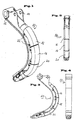
- Fig. 1 is a single gripper shell 10 of a gripping tool according to the invention, consisting of a prong shown.
- the gripper cup 10 is, as in the Fig. 1 , curved.
- the gripper shell 10 has bearings 12 and 14 in the usual way.
- the gripper shells 10 are made of a tough but not very resistant material.
- three wear parts 16, 18 and 20 are placed on the gripper shell 10, that here the main wear areas are covered by these wear elements 16, 18 and 20 protective.
- the wear elements 16, 18 and 20 are designed as castings, all three parts are designed in the form of circle segments.
- the wear elements which enclose the outer periphery of the tine of the gripper shell 10, holes 22 through which fastening screws are pluggable and screwed to the gripper cup 10 in the manner not shown here.
- a segment-like wear element 16, 18 or 20 can be selectively replaced with appropriate wear by simply loosening four screws, without the gripper shell 10 has to be removed.
- a particular advantage of this simple replacement of the wear element by a mechanical connection compared to a regeneration by welding is also that here the associated shrinkage stress associated with the regeneration welding, which represents a reduction in strength, can be safely avoided.
Landscapes
- Engineering & Computer Science (AREA)
- Mining & Mineral Resources (AREA)
- Civil Engineering (AREA)
- General Engineering & Computer Science (AREA)
- Structural Engineering (AREA)
- Mechanical Engineering (AREA)
- Earth Drilling (AREA)
- Crushing And Grinding (AREA)
- Gripping Jigs, Holding Jigs, And Positioning Jigs (AREA)
- Gripping On Spindles (AREA)
- Fishing Rods (AREA)
Description
- Die Erfindung betrifft ein Greifwerkzeug, vorzugsweise einen Mehrschalengreifer, mit mindestens einem Zinken, gemäß dem Oberbegriff des Anspruchs 1. Ein solches Greifwerkzeug ist aus
US 4 907 356 bekannt. - Mehrschalengreifer für den Materialumschlag dienen insbesondere der Verladung von Schüttgütern, Fein- und Grobschrott, Abbruchmaterial oder auch zum Verladen von VA-Stählen. Bei diesen Materialien handelt es sich um abrasive Materialien, die oft eine wesentlich höhere Härte aufweisen als das aufnehmende Werkzeug bzw. der Greifer. Hierdurch tritt nach relativ kurzer Zeit ein erheblicher Materialabtrag an den Greiferschalen auf. Aus konstruktiven Gründen, insbesondere wegen der erforderlichen Zähigkeit, sind die Greiferschalen aus einem nicht so widerstandsfähigen Material hergestellt, so dass der Verschleiß insgesamt sehr hoch ist.
- Um die Standzeit der Greiferschalen zu erhöhen, werden die Greiferschalen derzeit durch sogenanntes Aufpanzern mit einer Elektrode regeneriert. Diese Auftragsschweißung ist sehr zeitaufwendig und es ist zu dieser Regenerierung der Greiferschalen notwendig, die gesamte Greiferschale auszubauen.
- Aufgabe der Erfindung ist es, die Haltbarkeit der Greifwerkzeuge zu verlängern und die eventuell notwendige Regenerierung der Greifwerkzeuge zu vereinfachen und damit die Regenerierungskosten zu senken.
- Erfindungsgemäß wird diese Aufgabe durch die Kombination der Merkmale des Anspruchs 1 gelöst.
- Hierdurch werden die von dem abrasiven Material hauptsächlich angegriffenen Bereiche wirkungsvoll geschützt. Nach entsprechendem Verschleiß der zusätzlich vorgesehenen Verschleißelemente können diese in einfacher Weise ausgetauscht werden. Ferner können die einzelnen Segmente ausgetauscht werden.
- Besondere Ausgestaltungen der Erfindung ergeben sich aus dem sich an den Hauptanspruch anschließenden Unteransprüchen: Demnach kann das mindestens eine Verschleißelement aus verschleißfestem Material bestehen. Dieses verschleißfeste Material kann einerseits ein hoch verschleißbeständiges Material sein, das als solches nicht schweißbar ist, oder aber auch ein hoch vergütetes Material, das gerade noch schweißbar ist.
- Das mindestens eine Verschleißelement kann vorteilhaft über Bolzen und/oder Schrauben mit der Greiferschale wieder lösbar verbunden sein. Hierdurch ist ein besonders einfaches Austauschen der Verschleißelement möglich.
- Alternativ kann das Verschleißelement über eine Klebeverbindung mit der Greiferschale verbunden sein. In diesem Fall kann ein hoch verschleißbeständiges Material, das als solches nicht schweißbar ist, mit der Greiferschale verbunden werden. Dies ist natürlich auch für den vorgenannten Fall der Bolzen und/oder Schraubenverbindung möglich.
- Im Rahmen der Erfindung kann das Verschleißelement auch aus hoch vergütetem Material bestehen, welches zwar sehr widerstandsfähig ist, jedoch noch schweißbar ist. Dieses Verschleißelement kann über eine Heftschweißung mit der Greiferschale verbunden sein.
- Gemäß der Erfindung ist das Verschleißelement als Guss- oder Schmiedeteil gefertigt.
- Weitere Einzelheiten und Vorteile der Erfindung ergeben sich aus einem in der Zeichnung dargestellten Ausführungsbeispiel.
- Es zeigen:
- Fig. 1:
- eine Greiferschale eines erfindungsgemäßen Greifwerkzeugs in perspektivischer Ansicht.
- Fig. 2:
- das Greifwerkzeug nach
Fig. 1 in frontaler Ansicht, - Fig. 3:
- das Greifwerkzeug nach
Fig. 1 in Seitenansicht und - Fig. 4:
- das Greifwerkzeug gemäß
Fig. 1 in Rückansicht. - In
Fig. 1 ist eine einzelne Greiferschale 10 eines erfindungsgemäßen Greifwerkzeugs, bestehend aus einem Zinken, gezeigt. Die Greiferschale 10 ist, wie in derFig. 1 , gekrümmt ausgeführt. Die Greiferschale 10 weist in üblicher Weise Lagerstellen 12 und 14 auf. Grundsätzlich sind die Greiferschalen 10 aus einem zähen aber nicht sehr widerstandsfähigen Material hergestellt. Um die Greiferschalen 10 insbesondere im äußerem Bereich gegen die Abrasion des zu greifenden Materials zu schützen, sind in der hier dargestellten Ausführungsvariante drei Verschleißteile 16, 18 und 20 derart auf die Greiferschale 10 aufgesetzt, dass hier die Hauptverschleißbereiche durch diese Verschleißelemente 16, 18 und 20 schützend abgedeckt sind. Im hier dargestellten Ausführungsbeispiel sind die Verschleißelemente 16, 18 und 20 als Gussteile ausgeführt, wobei alle drei Teile in Form von Kreissegmenten gestaltet sind. - Seitlich weisen die Verschleißelemente, die den äußeren Umfang des Zinkens der Greiferschale 10 umschließen, Bohrungen 22 auf, durch die in hier nicht näher dargestellter Art und Weise Befestigungsschrauben steckbar und mit der Greiferschale 10 verschraubbar sind. Somit kann hier durch einfaches Lösen von vier Schrauben jeweils ein segmentartiges Verschleißelement 16, 18 oder 20 bei entsprechendem Verschleiß gezielt ausgewechselt werden, ohne dass die Greiferschale 10 ausgebaut werden muss. Ein besonderer Vorteil dieses einfachen Austausches des Verschleißelements durch eine mechanische Verbindung gegenüber einer Regenerierung durch Aufschweißen besteht auch darin, dass hier die mit dem Regenerierungsschweißen verbundene erzeugte Schrumpfspannungsgefahr, die eine Festigkeitsverminderung darstellt, sicher vermieden werden kann.
Claims (6)
- Greifwerkzeug, vorzugsweise Mehrschalengreifer, mit mindestens einer Greiferschale (10), die mindestens einen Zinken aufweist, wobei an der Greiferschale (10) mindestens ein Verschleißelement (16, 18, 20) derart angeordnet ist, daß die Hauptverschleißbereiche durch das mindestens eine Verschleißelement (16, 18, 20) abgedeckt sind,
dadurch gekennzeichnet,
dass mehrere als Guß- oder Schmiedeteil ausgebildete Verschleißelemente (16, 18, 20) segmentartig derartig auf welches eine Greiferschale (10) aufgesetzt sind, dass sie den äußeren Umfang des Zinkens des Greiferschale (10) umschließen. - Greifwerkzeug nach Anspruch 1, dadurch gekennzeichnet, dass das mindestens eine Verschleißelement (10) aus verschleißfestem Material besteht.
- Greifwerkzeug nach Anspruch 1 oder 2, dadurch gekennzeichnet, dass das mindestens eine Verschleißelement (16, 18, 20) aus hoch verschleißbeständigem Material über Bolzen und/oder Schrauben mit der Greiferschale (10) wieder lösbar verbunden ist.
- Greifwerkzeug nach einem der Ansprüche 1 oder 2, dadurch gekennzeichnet, dass das mindestens eine Verschleißelement (16, 18, 20) aus hoch verschleißbeständigem Material über eine Klebeverbindung mit der Greiferschale (10) verbunden ist.
- Greifwerkzeug nach einem der Ansprüche 1 oder 2, dadurch gekennzeichnet, dass das mindestens eine Verschleißelement (16, 18, 20) aus hochvergütetem Material über eine Heftschweißverbindung mit der Greiferschale (10) lösbar verbunden ist.
- Greifwerkzeug nach einem der Ansprüche 1 bis 6, dadurch gekennzeichnet, dass die Verschleißelemente (16, 18, 20) als Kreissegmente gestaltet sind.
Applications Claiming Priority (2)
| Application Number | Priority Date | Filing Date | Title |
|---|---|---|---|
| DE202004003910U | 2004-03-12 | ||
| DE202004003910U DE202004003910U1 (de) | 2004-03-12 | 2004-03-12 | Greifwerkzeug |
Publications (2)
| Publication Number | Publication Date |
|---|---|
| EP1574473A1 EP1574473A1 (de) | 2005-09-14 |
| EP1574473B1 true EP1574473B1 (de) | 2008-05-14 |
Family
ID=34802090
Family Applications (1)
| Application Number | Title | Priority Date | Filing Date |
|---|---|---|---|
| EP04030355A Expired - Lifetime EP1574473B1 (de) | 2004-03-12 | 2004-12-21 | Greifwerkzeug |
Country Status (5)
| Country | Link |
|---|---|
| US (1) | US7344175B2 (de) |
| EP (1) | EP1574473B1 (de) |
| AT (1) | ATE395296T1 (de) |
| DE (2) | DE202004003910U1 (de) |
| ES (1) | ES2304577T3 (de) |
Families Citing this family (9)
| Publication number | Priority date | Publication date | Assignee | Title |
|---|---|---|---|---|
| DE102006059894A1 (de) * | 2006-12-19 | 2008-06-26 | Terex Gmbh | Verschleißelement sowie damit ausgerüstetes Bauteil |
| USD610592S1 (en) * | 2008-10-24 | 2010-02-23 | Miller International Limited | Excavator bucket |
| CN102167233B (zh) * | 2011-03-21 | 2013-12-18 | 何嘉诚 | 一种抓具的液压旋转装置 |
| USD702738S1 (en) | 2011-07-01 | 2014-04-15 | Timothy M. Molnar | Attachment for equipment bucket |
| US9138829B2 (en) | 2013-09-03 | 2015-09-22 | Robert David Reid | Pipe welding fixture |
| US20160153178A1 (en) * | 2016-02-04 | 2016-06-02 | Caterpillar Inc. | Ground engaging tool with replaceable wear resistant cover |
| US10150651B2 (en) | 2017-01-18 | 2018-12-11 | Cranemasters, Inc. | Tank car lifting apparatus |
| USD967592S1 (en) * | 2020-09-14 | 2022-10-18 | Cranemasters, Inc. | Lifting arm |
| USD968745S1 (en) * | 2020-09-14 | 2022-11-01 | Cranemasters, Inc. | Lifting arm |
Family Cites Families (8)
| Publication number | Priority date | Publication date | Assignee | Title |
|---|---|---|---|---|
| DE1756642C3 (de) * | 1968-06-20 | 1973-09-20 | Demag Ag, 4100 Duisburg | Greifer in Verbundkonstruktion |
| DE8815474U1 (de) * | 1988-12-13 | 1989-05-03 | Liebherr-Hydraulikbagger Gmbh, 7951 Kirchdorf | Sichelförmiger Grundkörper einer Schale eines Mehrschalengreifers |
| DE3841940C1 (en) * | 1988-12-13 | 1990-05-23 | Liebherr-Hydraulikbagger Gmbh, 7951 Kirchdorf, De | Crescent-shaped basic body of a blade of a multi-bladed grab |
| US4907356A (en) * | 1989-01-23 | 1990-03-13 | Labounty Kenneth R | Slipper bucket for grapple |
| DE9102928U1 (de) * | 1990-11-30 | 1991-05-29 | Böhler Ladetechnik Vertriebs- u. Entwicklungsgesellschaft m.b.H., Kapfenberg | Greifereinrichtung für Ladeschaufeln |
| US6000108A (en) * | 1999-01-22 | 1999-12-14 | Roan; Jing-Wen | Towing hook structure |
| CA2358339C (en) * | 2001-10-05 | 2010-06-15 | Peninsula Alloy Inc. | Wear plate assembly |
| DE10350540A1 (de) * | 2003-10-29 | 2005-06-09 | Liebherr-Hydraulikbagger Gmbh | Grab- bzw.Greifwerkzeug |
-
2004
- 2004-03-12 DE DE202004003910U patent/DE202004003910U1/de not_active Expired - Lifetime
- 2004-12-21 ES ES04030355T patent/ES2304577T3/es not_active Expired - Lifetime
- 2004-12-21 EP EP04030355A patent/EP1574473B1/de not_active Expired - Lifetime
- 2004-12-21 DE DE502004007128T patent/DE502004007128D1/de not_active Expired - Lifetime
- 2004-12-21 AT AT04030355T patent/ATE395296T1/de active
-
2005
- 2005-03-11 US US11/077,848 patent/US7344175B2/en not_active Expired - Fee Related
Also Published As
| Publication number | Publication date |
|---|---|
| US7344175B2 (en) | 2008-03-18 |
| ATE395296T1 (de) | 2008-05-15 |
| DE202004003910U1 (de) | 2005-07-21 |
| EP1574473A1 (de) | 2005-09-14 |
| ES2304577T3 (es) | 2008-10-16 |
| DE502004007128D1 (de) | 2008-06-26 |
| US20050200146A1 (en) | 2005-09-15 |
Similar Documents
| Publication | Publication Date | Title |
|---|---|---|
| EP1574473B1 (de) | Greifwerkzeug | |
| CA2611695A1 (en) | Forged hammermill hammer | |
| WO2007124936A1 (de) | Schlegel für eine zerkleinerungsvorrichtung | |
| DE202006021235U1 (de) | Wechselschlegel | |
| DE102011051941A1 (de) | Mobile Brechanlage sowie mobile Brechanlagenanordnung | |
| WO2009027808A2 (en) | Cutter device mounted on casting breaking apparatus, and method of enhancing the hardness of cutter device | |
| EP2666549A2 (de) | Siebstern | |
| DE650607C (de) | Schlaegerkopf fuer Schlaegermuehlen | |
| EP1528165B1 (de) | Grab- oder Greifwerkzeug | |
| DE3538355C1 (de) | Werkzeugsatz fuer Loese- und Ladearbeiten | |
| EP2394741B1 (de) | Werkzeugeinsatz für eine vorrichtung zum zerkleinern von stückigem material und mit einem solchen einsatz ausgestattete vorrichtung | |
| DE102006029259A1 (de) | Stumpfschleifscheibe und Schleifleisten für diese | |
| DE19718837A1 (de) | Zerkleinerungselemente für Schredder-Rotoren in Form von Hämmern oder Schlegeln | |
| EP2052778B1 (de) | Wirbelstrommühle, sowie Mahlwerkzeug und Mahlring dafür | |
| DE102007044888B4 (de) | Schleuderkanten-Verschleißeinheit | |
| AT394147B (de) | Prallmuehle | |
| DE524146C (de) | Zerkleinerungsvorrichtung | |
| EP0241641B1 (de) | Schutzkappe für die vordersten Räder eines gepanzerten Kettenfahrzeugs | |
| DE102010000649A1 (de) | Verfahren zur Instandsetzung eines Verbundpanzerungselements sowie Reparatur-Set zur Durchführung der Instandsetzung | |
| DE2660595C2 (de) | Prallhammermühle | |
| DE185594C (de) | ||
| DE3520182A1 (de) | Verbundgussplatten zur verhinderung von abrasionsverschleiss | |
| AT18427B (de) | Zerkleinerungsmaschine. | |
| DE2714906B2 (de) | Verklammerung für bruchgefährdete Gußstücke | |
| DE102011085337B4 (de) | Schleißschutzvorrichtung und Verfahren zum Befestigen einer Schleißplatte |
Legal Events
| Date | Code | Title | Description |
|---|---|---|---|
| PUAI | Public reference made under article 153(3) epc to a published international application that has entered the european phase |
Free format text: ORIGINAL CODE: 0009012 |
|
| AK | Designated contracting states |
Kind code of ref document: A1 Designated state(s): AT BE BG CH CY CZ DE DK EE ES FI FR GB GR HU IE IS IT LI LT LU MC NL PL PT RO SE SI SK TR |
|
| AX | Request for extension of the european patent |
Extension state: AL BA HR LV MK YU |
|
| 17P | Request for examination filed |
Effective date: 20060221 |
|
| AKX | Designation fees paid |
Designated state(s): AT BE BG CH CY CZ DE DK EE ES FI FR GB GR HU IE IS IT LI LT LU MC NL PL PT RO SE SI SK TR |
|
| GRAP | Despatch of communication of intention to grant a patent |
Free format text: ORIGINAL CODE: EPIDOSNIGR1 |
|
| GRAS | Grant fee paid |
Free format text: ORIGINAL CODE: EPIDOSNIGR3 |
|
| GRAA | (expected) grant |
Free format text: ORIGINAL CODE: 0009210 |
|
| AK | Designated contracting states |
Kind code of ref document: B1 Designated state(s): AT BE BG CH CY CZ DE DK EE ES FI FR GB GR HU IE IS IT LI LT LU MC NL PL PT RO SE SI SK TR |
|
| REG | Reference to a national code |
Ref country code: GB Ref legal event code: FG4D Free format text: NOT ENGLISH |
|
| REG | Reference to a national code |
Ref country code: CH Ref legal event code: EP |
|
| REG | Reference to a national code |
Ref country code: IE Ref legal event code: FG4D Free format text: LANGUAGE OF EP DOCUMENT: GERMAN |
|
| REF | Corresponds to: |
Ref document number: 502004007128 Country of ref document: DE Date of ref document: 20080626 Kind code of ref document: P |
|
| PG25 | Lapsed in a contracting state [announced via postgrant information from national office to epo] |
Ref country code: SI Free format text: LAPSE BECAUSE OF FAILURE TO SUBMIT A TRANSLATION OF THE DESCRIPTION OR TO PAY THE FEE WITHIN THE PRESCRIBED TIME-LIMIT Effective date: 20080514 |
|
| REG | Reference to a national code |
Ref country code: ES Ref legal event code: FG2A Ref document number: 2304577 Country of ref document: ES Kind code of ref document: T3 |
|
| PG25 | Lapsed in a contracting state [announced via postgrant information from national office to epo] |
Ref country code: FI Free format text: LAPSE BECAUSE OF FAILURE TO SUBMIT A TRANSLATION OF THE DESCRIPTION OR TO PAY THE FEE WITHIN THE PRESCRIBED TIME-LIMIT Effective date: 20080514 |
|
| PG25 | Lapsed in a contracting state [announced via postgrant information from national office to epo] |
Ref country code: PL Free format text: LAPSE BECAUSE OF FAILURE TO SUBMIT A TRANSLATION OF THE DESCRIPTION OR TO PAY THE FEE WITHIN THE PRESCRIBED TIME-LIMIT Effective date: 20080514 |
|
| PG25 | Lapsed in a contracting state [announced via postgrant information from national office to epo] |
Ref country code: IS Free format text: LAPSE BECAUSE OF FAILURE TO SUBMIT A TRANSLATION OF THE DESCRIPTION OR TO PAY THE FEE WITHIN THE PRESCRIBED TIME-LIMIT Effective date: 20080914 |
|
| REG | Reference to a national code |
Ref country code: IE Ref legal event code: FD4D |
|
| PG25 | Lapsed in a contracting state [announced via postgrant information from national office to epo] |
Ref country code: SE Free format text: LAPSE BECAUSE OF FAILURE TO SUBMIT A TRANSLATION OF THE DESCRIPTION OR TO PAY THE FEE WITHIN THE PRESCRIBED TIME-LIMIT Effective date: 20080814 Ref country code: IE Free format text: LAPSE BECAUSE OF FAILURE TO SUBMIT A TRANSLATION OF THE DESCRIPTION OR TO PAY THE FEE WITHIN THE PRESCRIBED TIME-LIMIT Effective date: 20080514 Ref country code: LT Free format text: LAPSE BECAUSE OF FAILURE TO SUBMIT A TRANSLATION OF THE DESCRIPTION OR TO PAY THE FEE WITHIN THE PRESCRIBED TIME-LIMIT Effective date: 20080514 Ref country code: PT Free format text: LAPSE BECAUSE OF FAILURE TO SUBMIT A TRANSLATION OF THE DESCRIPTION OR TO PAY THE FEE WITHIN THE PRESCRIBED TIME-LIMIT Effective date: 20081014 Ref country code: DK Free format text: LAPSE BECAUSE OF FAILURE TO SUBMIT A TRANSLATION OF THE DESCRIPTION OR TO PAY THE FEE WITHIN THE PRESCRIBED TIME-LIMIT Effective date: 20080514 Ref country code: CZ Free format text: LAPSE BECAUSE OF FAILURE TO SUBMIT A TRANSLATION OF THE DESCRIPTION OR TO PAY THE FEE WITHIN THE PRESCRIBED TIME-LIMIT Effective date: 20080514 |
|
| PG25 | Lapsed in a contracting state [announced via postgrant information from national office to epo] |
Ref country code: SK Free format text: LAPSE BECAUSE OF FAILURE TO SUBMIT A TRANSLATION OF THE DESCRIPTION OR TO PAY THE FEE WITHIN THE PRESCRIBED TIME-LIMIT Effective date: 20080514 Ref country code: RO Free format text: LAPSE BECAUSE OF FAILURE TO SUBMIT A TRANSLATION OF THE DESCRIPTION OR TO PAY THE FEE WITHIN THE PRESCRIBED TIME-LIMIT Effective date: 20080514 |
|
| PLBE | No opposition filed within time limit |
Free format text: ORIGINAL CODE: 0009261 |
|
| STAA | Information on the status of an ep patent application or granted ep patent |
Free format text: STATUS: NO OPPOSITION FILED WITHIN TIME LIMIT |
|
| 26N | No opposition filed |
Effective date: 20090217 |
|
| PG25 | Lapsed in a contracting state [announced via postgrant information from national office to epo] |
Ref country code: EE Free format text: LAPSE BECAUSE OF FAILURE TO SUBMIT A TRANSLATION OF THE DESCRIPTION OR TO PAY THE FEE WITHIN THE PRESCRIBED TIME-LIMIT Effective date: 20080514 Ref country code: BG Free format text: LAPSE BECAUSE OF FAILURE TO SUBMIT A TRANSLATION OF THE DESCRIPTION OR TO PAY THE FEE WITHIN THE PRESCRIBED TIME-LIMIT Effective date: 20080814 |
|
| BERE | Be: lapsed |
Owner name: LIEBHERR-HYDRAULIKBAGGER G.M.B.H. Effective date: 20081231 |
|
| PG25 | Lapsed in a contracting state [announced via postgrant information from national office to epo] |
Ref country code: MC Free format text: LAPSE BECAUSE OF NON-PAYMENT OF DUE FEES Effective date: 20081231 |
|
| REG | Reference to a national code |
Ref country code: CH Ref legal event code: PL |
|
| PG25 | Lapsed in a contracting state [announced via postgrant information from national office to epo] |
Ref country code: BE Free format text: LAPSE BECAUSE OF NON-PAYMENT OF DUE FEES Effective date: 20081231 |
|
| PG25 | Lapsed in a contracting state [announced via postgrant information from national office to epo] |
Ref country code: LI Free format text: LAPSE BECAUSE OF NON-PAYMENT OF DUE FEES Effective date: 20081231 Ref country code: CH Free format text: LAPSE BECAUSE OF NON-PAYMENT OF DUE FEES Effective date: 20081231 |
|
| PG25 | Lapsed in a contracting state [announced via postgrant information from national office to epo] |
Ref country code: LU Free format text: LAPSE BECAUSE OF NON-PAYMENT OF DUE FEES Effective date: 20081221 Ref country code: HU Free format text: LAPSE BECAUSE OF FAILURE TO SUBMIT A TRANSLATION OF THE DESCRIPTION OR TO PAY THE FEE WITHIN THE PRESCRIBED TIME-LIMIT Effective date: 20081115 Ref country code: CY Free format text: LAPSE BECAUSE OF FAILURE TO SUBMIT A TRANSLATION OF THE DESCRIPTION OR TO PAY THE FEE WITHIN THE PRESCRIBED TIME-LIMIT Effective date: 20080514 |
|
| PG25 | Lapsed in a contracting state [announced via postgrant information from national office to epo] |
Ref country code: TR Free format text: LAPSE BECAUSE OF FAILURE TO SUBMIT A TRANSLATION OF THE DESCRIPTION OR TO PAY THE FEE WITHIN THE PRESCRIBED TIME-LIMIT Effective date: 20080514 |
|
| PG25 | Lapsed in a contracting state [announced via postgrant information from national office to epo] |
Ref country code: GR Free format text: LAPSE BECAUSE OF FAILURE TO SUBMIT A TRANSLATION OF THE DESCRIPTION OR TO PAY THE FEE WITHIN THE PRESCRIBED TIME-LIMIT Effective date: 20080815 |
|
| REG | Reference to a national code |
Ref country code: FR Ref legal event code: PLFP Year of fee payment: 12 |
|
| REG | Reference to a national code |
Ref country code: FR Ref legal event code: PLFP Year of fee payment: 13 |
|
| REG | Reference to a national code |
Ref country code: FR Ref legal event code: PLFP Year of fee payment: 14 |
|
| PGFP | Annual fee paid to national office [announced via postgrant information from national office to epo] |
Ref country code: NL Payment date: 20171220 Year of fee payment: 14 Ref country code: FR Payment date: 20171221 Year of fee payment: 14 |
|
| PGFP | Annual fee paid to national office [announced via postgrant information from national office to epo] |
Ref country code: GB Payment date: 20171221 Year of fee payment: 14 Ref country code: AT Payment date: 20171221 Year of fee payment: 14 |
|
| PGFP | Annual fee paid to national office [announced via postgrant information from national office to epo] |
Ref country code: DE Payment date: 20171229 Year of fee payment: 14 Ref country code: ES Payment date: 20180117 Year of fee payment: 14 |
|
| PGFP | Annual fee paid to national office [announced via postgrant information from national office to epo] |
Ref country code: IT Payment date: 20171229 Year of fee payment: 14 |
|
| REG | Reference to a national code |
Ref country code: DE Ref legal event code: R119 Ref document number: 502004007128 Country of ref document: DE |
|
| REG | Reference to a national code |
Ref country code: NL Ref legal event code: MM Effective date: 20190101 |
|
| REG | Reference to a national code |
Ref country code: AT Ref legal event code: MM01 Ref document number: 395296 Country of ref document: AT Kind code of ref document: T Effective date: 20181221 |
|
| GBPC | Gb: european patent ceased through non-payment of renewal fee |
Effective date: 20181221 |
|
| PG25 | Lapsed in a contracting state [announced via postgrant information from national office to epo] |
Ref country code: NL Free format text: LAPSE BECAUSE OF NON-PAYMENT OF DUE FEES Effective date: 20190101 |
|
| PG25 | Lapsed in a contracting state [announced via postgrant information from national office to epo] |
Ref country code: IT Free format text: LAPSE BECAUSE OF NON-PAYMENT OF DUE FEES Effective date: 20181221 Ref country code: FR Free format text: LAPSE BECAUSE OF NON-PAYMENT OF DUE FEES Effective date: 20181231 Ref country code: DE Free format text: LAPSE BECAUSE OF NON-PAYMENT OF DUE FEES Effective date: 20190702 |
|
| PG25 | Lapsed in a contracting state [announced via postgrant information from national office to epo] |
Ref country code: GB Free format text: LAPSE BECAUSE OF NON-PAYMENT OF DUE FEES Effective date: 20181221 Ref country code: AT Free format text: LAPSE BECAUSE OF NON-PAYMENT OF DUE FEES Effective date: 20181221 |
|
| REG | Reference to a national code |
Ref country code: ES Ref legal event code: FD2A Effective date: 20200203 |
|
| PG25 | Lapsed in a contracting state [announced via postgrant information from national office to epo] |
Ref country code: ES Free format text: LAPSE BECAUSE OF NON-PAYMENT OF DUE FEES Effective date: 20181222 |
|
| P01 | Opt-out of the competence of the unified patent court (upc) registered |
Effective date: 20230607 |