EP1571107B1 - Cassette pour l'alimentation en papier, dispositif de détection de la la taille d'un support d'enregistrement et dispositif de formation d'image - Google Patents
Cassette pour l'alimentation en papier, dispositif de détection de la la taille d'un support d'enregistrement et dispositif de formation d'image Download PDFInfo
- Publication number
- EP1571107B1 EP1571107B1 EP05004801A EP05004801A EP1571107B1 EP 1571107 B1 EP1571107 B1 EP 1571107B1 EP 05004801 A EP05004801 A EP 05004801A EP 05004801 A EP05004801 A EP 05004801A EP 1571107 B1 EP1571107 B1 EP 1571107B1
- Authority
- EP
- European Patent Office
- Prior art keywords
- movable member
- recording medium
- paper feed
- pressed
- portions
- Prior art date
- Legal status (The legal status is an assumption and is not a legal conclusion. Google has not performed a legal analysis and makes no representation as to the accuracy of the status listed.)
- Expired - Lifetime
Links
Images




Classifications
-
- B—PERFORMING OPERATIONS; TRANSPORTING
- B65—CONVEYING; PACKING; STORING; HANDLING THIN OR FILAMENTARY MATERIAL
- B65H—HANDLING THIN OR FILAMENTARY MATERIAL, e.g. SHEETS, WEBS, CABLES
- B65H1/00—Supports or magazines for piles from which articles are to be separated
- B65H1/26—Supports or magazines for piles from which articles are to be separated with auxiliary supports to facilitate introduction or renewal of the pile
- B65H1/266—Support fully or partially removable from the handling machine, e.g. cassette, drawer
-
- B—PERFORMING OPERATIONS; TRANSPORTING
- B65—CONVEYING; PACKING; STORING; HANDLING THIN OR FILAMENTARY MATERIAL
- B65H—HANDLING THIN OR FILAMENTARY MATERIAL, e.g. SHEETS, WEBS, CABLES
- B65H2220/00—Function indicators
- B65H2220/09—Function indicators indicating that several of an entity are present
-
- B—PERFORMING OPERATIONS; TRANSPORTING
- B65—CONVEYING; PACKING; STORING; HANDLING THIN OR FILAMENTARY MATERIAL
- B65H—HANDLING THIN OR FILAMENTARY MATERIAL, e.g. SHEETS, WEBS, CABLES
- B65H2511/00—Dimensions; Position; Numbers; Identification; Occurrences
- B65H2511/10—Size; Dimensions
-
- B—PERFORMING OPERATIONS; TRANSPORTING
- B65—CONVEYING; PACKING; STORING; HANDLING THIN OR FILAMENTARY MATERIAL
- B65H—HANDLING THIN OR FILAMENTARY MATERIAL, e.g. SHEETS, WEBS, CABLES
- B65H2511/00—Dimensions; Position; Numbers; Identification; Occurrences
- B65H2511/20—Location in space
-
- B—PERFORMING OPERATIONS; TRANSPORTING
- B65—CONVEYING; PACKING; STORING; HANDLING THIN OR FILAMENTARY MATERIAL
- B65H—HANDLING THIN OR FILAMENTARY MATERIAL, e.g. SHEETS, WEBS, CABLES
- B65H2553/00—Sensing or detecting means
- B65H2553/20—Sensing or detecting means using electric elements
- B65H2553/25—Contact switches
Definitions
- the present invention relates to a paper feed cassette to be used in feeding a recording medium in an image formation device, a recording medium size detector for detecting the size of the recording medium loaded on the paper feed cassette, and an image formation device comprising this recording medium size detector.
- the paper feed cassette having a recording medium loaded thereon is installed in a body case, the recording medium loaded on a paper feed cassette is fed, and image is formed on such recording medium.
- This kind of paper feed cassette comprises a side fence abut on the end fence in the width direction orthogonal to the feeding direction of the recording medium loaded on this cassette body, and an end fence abut on the rear end face in the feeding direction of the recording medium loaded on this cassette body, and the loading position of the recording medium is determined by sliding the side fence and end fence and abutting them on the recording medium.
- an image formation device employing a paper feed cassette comprising such a slidable side fence and end fence
- a type which comprises a mechanism for detecting the size of the recording medium loaded on the paper feed cassette from the slide position of the side fence and end fence (e.g., this is disclosed in the gazettes of Japanese Patent Laid-Open Publication No. 2000-118729 and Japanese Patent Laid-Open Publication No. H6-32489 ).
- a measurement piece which slides in synchronization with the movement of the side fence, and a portion to be measured that rotates or slides in synchronization with the movement of the end fence are provided to the paper feed cassette.
- First and second ranging means positioned so as to face the measuring piece/portion to be measured when the paper feed cassette is installed in the case body are provided to the body case of the image formation device to which the paper feed cassette is installed.
- the distance between the measuring piece and first ranging means, and the distance between the measure portion and second ranging means upon installing the paper feed cassette in the body case will change.
- the slide position of the side fence and end fence that is, the size of the recording medium loaded on the paper feed cassette can be detected.
- a paper sheet size recognition member that rises and falls in synchronization with the movement of a guide member (side fence), and a paper sheet size recognition member that rises and falls in synchronization with the movement of a guide member (end fence) are provided to the paper feed cassette.
- These paper size recognition members are disposed in mutually adjacent positions in close proximity.
- a plurality of actuators to be selectively pressed with the protruding paper sheet size recognition members is provided to the body case of the image formation device to which the paper feed cassette is installed.
- the paper sheet size recognition member rises or falls according to the size of the recording medium loaded on the paper feed cassette, the plurality of actuators is selectively pressed with the paper size recognition members protruding when the paper feed cassette is installed in the body case, and the size of the recording medium loaded on the paper feed cassette is detected depending on which actuator is being pressed.
- the measuring piece that slides in synchronization with the movement of the side fence and the portion to be measured that rotates or slides in synchronization with the movement of the end fence function independently upon detecting the size of the recording medium.
- the ranging means for measuring the distance to the measuring piece and the ranging means for measuring the distance to the portion to be measured must be provided separately.
- the paper sheet size recognition member that rises and falls in synchronization with the movement of a guide member (side fence), and the paper sheet size recognition member that rises and falls in synchronization with the movement of a guide member (end fence) function independently upon detecting the size of the recording medium.
- two types of actuators namely, anactuator for detecting the rising and falling state of the paper sheet size recognition member that rises and falls in synchronization with the movement of the guide member (side fence), and an actuator for detecting the rising and falling state of the paper sheet size recognition member that rises and falls in synchronization with the movement of the guide member (end fence) must be provided.
- EP-A-0 285 454 discloses the following:
- an object of the present invention is to provide a paper feed cassette, a recording medium size detector capable of detecting, with a simple constitution and with high accuracy, the size of the recording medium loaded on the paper feed cassette, and an image formation device comprising this recording medium size detector.
- a paper feed cassette of the present invention comprises a cassette body capable of loading a plurality of recording mediums thereon and detachable from a body case; a side fence provided slidably to the cassette body which abuts on the end face in the width direction orthogonal to the feeding direction of the recording medium loaded on this cassette body; an end fence provided slidably to the cassette body which abuts on the rear end face in the feeding direction of the recording medium loaded on this cassette body; a first movable member having formed thereon a plurality of first convex portions at the peripheral edge thereof, which selectively makes the first convex portions face a plurality of portions to be pressed of a size detection switch provided to the body case for detecting the size of the recording medium loaded in said cassette body, and is mounted on the cassette body movably in the direction of varying the portions to be pressed facing the first convex portion in synchronization with the sliding motion of the side fence; and a second movable member having formed thereon a plurality of second convex portions
- the first movable member and the second movable member are disposed at a position where the first convex portion and the second convex portion are overlapping, a plurality of synthesized convex portions for selectively pressing the portions to be pressed are formed by overlapping the first convex portion and the second convex portion, and the width size and position of these synthesized convex portions vary in synchronization with the sliding motion of the side fence and the end fence according to the size of the recording medium loaded on the cassette body.
- a recording medium size detector of the present invention is provided with a paper feed cassette.
- the paper feed cassette comprises a cassette body capable of loading a plurality of recording mediums thereon and detachable from a body case; a side fence provided slidably to the cassette body which abuts on the end face in the width direction orthogonal to the feeding direction of the recording medium loaded on this cassette body; an end fence provided slidably to the cassette body which abuts on the rear end face in the feeding direction of the recording medium loaded on this cassette body; a first movable member having formed thereon a plurality of first convex portions at the peripheral edge thereof, which selectively makes the first convex portions face a plurality of portions to be pressed of a size detection switch provided to the body case for detecting the size of the recording medium loaded in the cassette body, and is mounted on the cassette body movably in the direction of varying the portions to be pressed facing the first convex portion in synchronization with the sliding motion of the side fence; and a second mov
- the first movable member and the second movable member are disposed at a position where the first convex portion and the second convex portion are overlapping, a plurality of synthesized convex portions for selectively pressing the portions to be pressed are formed by overlapping said first convex portion and the second convex portion, and the width size and position of these synthesized convex portions vary in synchronization with the sliding motion of the side fence and the end fence according to the size of the recording medium loaded on the cassette body; and a size detection switch having a plurality of portions to be pressed which are selectively pressed by the synthesized portions provided to the paper feed cassette installed in the body case.
- An image formation device of the present invention is provided with a recording medium size detector which comprises a paper feed cassette.
- the paper feed cassette comprises a cassette body capable of loading a plurality of recording mediums thereon and detachable from a body case; a side fence provided slidably to the cassette body which abuts on the end face in the width direction orthogonal to the feeding direction of the recording medium loaded on this cassette body; an end fence provided slidably to the cassette body which abuts on the rear end face in the feeding direction of the recording medium loaded on this cassette body; a first movable member having formed thereon a plurality of first convex portions at the peripheral edge thereof, which selectively makes the first convex portions face a plurality of portions to be pressed of a size detection switch provided to the body case for detecting the size of the recording medium loaded in the cassette body, and is mounted on the cassette body movably in the direction of varying the portions to be pressed facing the first convex portion in synchronization with the sliding motion of the side fence
- the first movable member and the second movable member are disposed at a position where the first convex portion and the second convex portion are overlapping, a plurality of synthesized convex portions for selectively pressing the portions to be pressed are formed by overlapping the first convex portion and the second convex portion, and the width size and position of these synthesized convex portions vary in synchronization with the sliding motion of the side fence and the end fence according to the size of the recording medium loaded on the cassette body; and a size detection switch having a plurality of portions to be pressed which are selectively pressed by the synthesized portions provided to the paper feed cassette installed in the body case; a device for separately feeding the recording medium, one by one, from the paper feed cassette installed in the body case; and a printer engine for forming an image in accordance with the image data input to the recording medium separately fed.
- FIG. 1 is a front view showing the schematic configuration inside the copy machine 1 according to an embodiment of the present invention.
- a printer engine 3 and a fixation device 4 are provided to the upper part inside a body case 2 of the copy machine 1, and a plurality of paper feed cassettes 5 is detachably installed at the lower part inside the body case 2.
- AnADF 6 for automatically feeding the manuscript, which is the object to be read; a contact glass 7 to which the manuscript as the object to be read is mounted; and an image reading device 8 for reading the manuscript automatically fed with the ADF 6 or mounted on the contact glass 7 are disposed at the upper part of the body case 2.
- a bulk paper feed device 9 and a sheet post-processing device 10 are disposed on the side of the body case 2.
- a transport path for transporting the recording medium S fed from the paper feed cassette 5 or the bulk paper feed device 9 to the paper catch tray 11a, 11b is formed via the printer engine 3 and fixation device 4.
- the printer engine 3 is formed from a photo conductor 12, a charging device 13, a development device 14, a transfer/transport device 15, a cleaning device 16, an optical writing device 17, and so on.
- a part of this printer engine 3 is made to be a process cartridge 18 which houses the photo conductor 12, charging device 13, development device 14 and cleaning device 16 in a cartridge case, in an integrated manner.
- the process cartridge 18 is detachably installed in the body case 2.
- the photo conductor 12 is acylindrical member that is rotatably driven around the axis, and a conductive support, an under coat layer, a charge generating layer, a charge transport layer and so on are laminated and formed in this order from the inner periphery thereof.
- the surface of this photo conductor 12 is charged uniformly, and, by exposure being performed according to the image data in relation to the surface of the uniformly charged photo conductor 12, an electrostatic latent image is written.
- the charging device 13 uniformly charges the surface of the photo conductor 12.
- the charging device 13 may be a corona charger employing the corona discharge system for charging the surface of the photo conductor 12 in a non-contact manner, or may be a contact charge roller that is disposed in contact with the surface of the photo conductor 12, and which charges the surface of the photo conductor 12 by applying a charge voltage between the photo conductors 12.
- the optical writing device 17 emits light in accordance with the image data, and exposes and scans the surface of the photo conductor 12 charged uniformly with the charging device 13. As a result of this exposure and scanning, an electrostatic latent image is written on the surface of the photo conductor 12.
- this is formed from a light source such as a laser diode for emitting light, a polygon mirror for scanning the light emitted from the light source, a motor for rotating the polygon mirror, a lens or mirror for guiding the light scanned with the polygon mirror to the photo conductor 12, and so on.
- the development device 14 comprises a development roller (not shown) for supplying the toner supplied from the toner bottle (not shown) to the surface of the photo conductor 12.
- a development roller for supplying the toner supplied from the toner bottle (not shown) to the surface of the photo conductor 12.
- the transfer/transport device 15 applies a transfer voltage between the photo conductors 12 when the recording medium S fed from the paper feed cassette 5 or the bulk paper feed device 9 and transported on the transport path is sandwiched between the transfer/transport device 15 and the photo conductor 12, and transfers the toner image formed on the surface of the photo conductor 12 onto the recording medium S . Further, it transports the recording medium S to which the toner image has been transferred toward the fixation device 4.
- the cleaning device 16 collects the toner remaining on the photo conductor 12 that was not transferred onto the recording medium S.
- the fixation device 4 has a fixation roller 4a having a built-in heater and a pressuring roller 4b pressed against this fixation roller 4a frombelow, and applies heat and pressure when the recording medium S to which the toner image has been transferred passes through between the fixation roller 4a and pressuring roller 4b, dissolves the toner and fixes the toner image onto the recording medium S.
- the image reading device 8 reads the image of the manuscript, and the printer engine 3 begins to form the image thereof according to the read results.
- image data is created based on the read results of the image reading device 8, light is emitted from the optical writing device 17 according to such image data, and the surface of the photo conductor 12 is exposed and scanned pursuant to the emitted light.
- An electrostatic latent image is formed on the surface of the photo conductor 12 based on the exposure scanning, and this electrostatic latent image is created into a microscopy image as the toner image with the toner supplied from the development device 14.
- the recording medium S of a designated size, or the recording medium S of a size automatically selected according to the manuscript size or the like is separately fed, one by one, with a means for separately feeding such recording medium S from the paper feed cassette 5 or the bulk paper feed device 9, and is transported on the transport path toward the printer engine 3.
- the recording medium S transported on the transport path is sent to the toner image transfer position (contact position of the transfer/transport device 15 and photo conductor 12) in accordance with the image formation operation timing in the printer engine 3, and the toner image on the photo conductor 12 is transferred onto the recording medium S.
- the recording medium S with the toner image transferred thereto is transported to the fixation device 4, and, after being fixed with the fixation device 4, is discharged directly to the paper catch tray 11a, or discharged to the paper catch tray 11b after being subject to post-processing such as stapling with the sheet post-processing device 10.
- FIG. 2 is a perspective view showing the paper feed cassette and size detection switch of the copy machine
- FIG. 3 is a plan view of the paper feed cassette positioned at the mounting point inside the body case of the copy machine, and the size detection switch provided inside the body case
- FIG. 4 is a plan view showing the first movable member mounted on the back side of the recording medium load face of the paper feed cassette
- FIG. 5 is a plan view showing the second movable member mounted on the recording medium load face of the paper feed cassette.
- the paper feed cassette 5 has a box shaped cassette body 5a in which the upper end face thereof is opened, and a pair of side fences 19a, 19b and one end fence 20 are slidably mounted on this cassette body 5a. Further, as shown in FIG. 3 , a bottom plate 21 for raising the front edge side of the feeding direction of the loaded recording medium S is provided to a part of the cassette body 5a, which is also a part of the recording medium load face 5b to which the recording medium S is loaded.
- the direction of arrow A illustrated in FIG. 2 and FIG. 3 is the attaching and detaching direction of the paper feed cassette 5 in relation to the body case 2.
- Guide grooves 22, 22a extending along the width direction orthogonal to the feeding direction of the recording medium S (direction of arrow B illustrated in FIG. 3 ) loaded on the recording medium load face 5b, and a guide grooves 23 extending along the feeding direction of the recording medium S loaded on the recording medium load face 5b are formed on the recording medium load face 5a.
- the side fences 19a, 19b are slidably fitted into the guide groove 22, and the side fences 19a, 19b are capable of abutting on the end face in the width direction orthogonal to the feeding direction of the recording medium S loaded on the recording medium load face 5b.
- the end fence 20 is slidably fitted into the guide groove 23, and the end fence 20 is capable of abutting on the rear end face in the width direction orthogonal to the feeding direction of the recording medium S loaded on the recording medium load face 5b.
- a rack (not shown) disposed on the back side of the recording medium load face 5b is connected to the side fences 19a, 19b, and these racks are connected via a pinion.
- the pair of side fences 19a, 19b has a constitution of sliding the same distance of approaching and separating from each other based on the pinion mechanism.
- a first movable member 24 formed in a fan shape as shown in FIG. 4 and a second movable member 25 formed in the shape of a ginkgo biloba as shown in FIG. 5 are overlappingly disposed on the back face of the recording medium load face 5b, and these are mounted rotatably around the axis of a common spindle 26.
- the first movable member 24 and the second movable member 25 are formed from a single tabular member, and are disposed in parallel to the recording medium load face 5a.
- the first movable member 24 and second movable member 25 have an arcuate peripheral edge set the same distance from the axis of the spindle 26, and a plurality of first convex portions 27 is formed on the arcuate peripheral edge of the first movable member 24, and a plurality of second convex portions 28 is formed on the arcuate peripheral edge of the second movable member 25.
- the first movable member 24 and second movable member 25 are positioned to be within the outside dimension of the case body 5a.
- a pin 30 fixed to the side fence 19a and inserted into the guide groove 22a is slidably fitted into the first slide groove 29.
- a pin 32 fixed to the end fence 20 and inserted into the guide groove 23 is slidably fitted into the second slide groove 31.
- the first convex portion 27 of the first movable member 24 and the second convex portion 28 of the second movable member 25 will be positioned in anoverlappingmanner, and a plurality of synthesized convex portions 33 will be formed by overlapping the first convex portion 27 and second convex portion 28.
- the first movable member 24 will rotate around the axis of the spindle 26 in synchronization with the sliding motion of the side fences 19a, 19b, and the second movable member 25 will rotate around the axis of the spindle 26 in synchronization with the sliding motion of the end fence 20.
- the overlapping state of the first convex portion 27 and the second convex portion 28 will change, and the width size and position of the synthesized convex portion 33 will change along the alignment direction of the portion to be pressed provided to the size detection switch described later.
- the width size and position of the synthesized convex portion 33 will change in accordance with the size of the recording medium S loaded on the recording medium load face 5b.
- a size detection switch 35 having a plurality of portions to be pressed 34 (34A, 34B 34C, 34D, 34E) to be selectively pressed with the synthesized convex portion 33 is mounted inside the body case 2 at the front edge of the installation direction of the paper feed cassette 5.
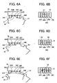
- FIG. 6 is a diagram showing the pressed state of the portion to be pressed 34 being pressed with the first convex portion 27, second convex portion 28 and synthesized convex portion 33 in a case where the paper feed cassette 5 loaded with the recording medium S of an A4 landscape (A4Y) on the recording medium load face 5b is installed in the body case 2.
- FIG. 6A and FIG. 6B are diagrams showing the positional relationship of the portion to be pressed 34 and the first convex portion 27. Two portions to be pressed 34B, 34C and the first convex portion 27 are facing each other, and the portions to be pressed 34B, 34C being pressed with the first convex portion 27 are turned ON.
- FIG. 6C and FIG. 6D are diagrams showing the positional relationship of the portion to be pressed 34 and the second convex portion 28.
- Three portions to be pressed 34B, 34D, 34E and the second convex portion 28 are facing each other, and the portions to be pressed 34B, 34D, 34E being pressed with the second convex portion 28 are turned ON.
- FIG. 6E and FIG. 6F are diagrams showing the positional relationship of the portion to be pressed 34 and the synthesized convex portion 33.
- Four portions to be pressed 34B, 34C, 34D, 34E and the synthesized convex portion 33 are facing each other, and the portions to be pressed 34B, 34C, 34D, 34E being pressed with the synthesized convex portion 33 are turned ON.
- FIG. 7 is an explanatory diagram showing the size (Y is landscape, T is portrait) of the recording medium S loaded on the recording medium load face 5b, and pressed state of the portion to be pressed 34 being pressed with the first convex portion 27, second convex portion 28 and synthesized convex portion 33 in such a case.
- "0” implies that the portion to be pressed 34 is not being pressed and is turned OFF.
- "1” implies that the portion to be pressed 34 is being pressed and is turned ON.
- the members to be pressed 34 cannot be reliably pressed with the first convex portion 27 or second convex portion 28 independently since the spacing between the portions to be pressed 34 cannot be made large, and the width size of the first convex portion 27 and second convex portion 28 cannot be made large.
- the second convex portion 28 supplements the pressing operation of the first convex portion 27 to enable the reliable pressing of the portion to be pressed 34B.
- FIG. 8 is a side view showing the relationship of the width size (vertical width size) of the overlapping direction of the first movable member 24 and second movable member 25 in the synthesized convex portion 33, and the width size in the same direction of this overlapping direction in the portion to be pressed 34.
- the width size (same as the width size in the overlapping direction of the first movable member 24 and second movable member 25) L1 of the overlapping direction of the first movable member 24 and second movable member 25 in the synthesized convex portion 33 is set to be smaller than the wide size L2 in the same direction of this overlapping direction in the portion to be pressed 34.
- the synthesized convex portion 33 presses the portion to be pressed 34, it is possible to prevent the synthesized convex portion 33 from departing from the pressing area of the portion to be pressed 34, and the synthesized convex portion 33 will therefore be able to reliably press the portion to be pressed 34, and the performance of detecting the size of the recording medium S with the size detection switch 35 can be improved.
- a gap size L0 capable of preventing the first movable member 24 and the second movable member 25 from coming into contact may be secured between the first movable member 24 and the second movable member 25 in relation to the disposition of the overlapping direction of the first movable member 24 and the second movable member 25.
- this gap size L0 the rotation of the first movable member 24 and the rotation of the second movable member 25 can be conducted smoothly without contacting each other.
- a part of the printer engine 3 is constituted with the process cartridge 18.
- the present invention may also be employed in a paper feed cassette comprising only one side fence and which positions the loaded recording medium S on one side.
- the present invention yields the following effects:
Landscapes
- Engineering & Computer Science (AREA)
- Mechanical Engineering (AREA)
- Sheets, Magazines, And Separation Thereof (AREA)
Claims (14)
- Cassette d'alimentation de papier (5), comprenant :un corps de cassette (5a) capable de charger une pluralité de supports d'enregistrement sur lui-même et détachable d'un casier de corps (2) ;un rideau latéral (19) prévu en coulissement sur ledit corps de cassette (5a) et venant en butée contre la face terminale, dans la direction en largeur orthogonale à la direction d'alimentation du support d'enregistrement chargé sur ce corps de cassette (5a) ;un rideau terminal (20) prévu en coulissement sur ledit corps de cassette (5a) et venant en butée contre la face terminale arrière dans la direction d'alimentation du support d'enregistrement chargé sur ce corps de cassette (5a);un premier élément mobile (24), sur lequel sont formées une pluralité de premières portions convexes (27) au niveau de la bordure périphérique de celui-ci, qui amène sélectivement lesdites premières portions convexes (27) en face d'une pluralité de portions (34A-34E) à presser d'un commutateur de détection de taille (35) prévu sur ledit casier de corps (2) pour détecter la taille du support d'enregistrement chargé dans ledit corps de cassette (5a), et est monté sur le ledit corps de cassette (5a) de façon mobile dans la direction pour faire varier lesdites portions (34A-34E) à presser en face de l'une au moins desdites premières portions convexes (27) en synchronisme avec le mouvement de coulissement dudit rideau latéral (19) ; et un second élément mobile (25), sur lequel sont formées une pluralité de secondes portions convexes (28) au niveau de la bordure périphérique de celui-ci, qui amène sélectivement lesdites secondes portions convexes (28) en face d'une pluralité desdites portions (34A-34E) à presser, et est monté sur ledit corps de cassette (5a) de façon mobile dans la direction pour faire varier lesdites portions (34A-34E) à presser en face de l'une au moins desdites secondes portions convexes (28) en synchronisme avec le mouvement de coulissement dudit rideau terminal (20) ;caractérisée en ce que le ledit premier élément mobile (24) et ledit second élément mobile (25) sont disposés à une position à laquelle l'une au moins desdites premières portions convexes (27) et l'une au moins desdites secondes portions convexes (28) sont en chevauchement, une pluralité de portions convexes synthétisées pour presser sélectivement lesdites portions (34A-34E) à presser peuvent être formées par chevauchement de l'une au moins desdites premières portions convexes (27) et de l'une au moins desdites secondes portions convexes (28), et la taille en largeur et la position de ces portions convexes synthétisées varie en synchronisme avec le mouvement de coulissement dudit rideau latéral (19) et dudit rideau terminal (20) selon la taille du support d'enregistrement chargé sur ledit corps de cassette (5a).
- Cassette d'alimentation de papier (5) selon la revendication 1, dans laquelle la taille en largeur d'une partie au moins desdites portions convexes synthétisées est formée plus grande que la taille en largeur lorsque ladite au moins une desdites premières portions convexes et ladite au moins une desdites secondes portions convexes qui forment au moins une partie desdites portions convexes synthétisées sont indépendantes.
- Cassette d'alimentation de papier (5) selon la revendication 1, dans laquelle ledit premier élément mobile (24) et ledit second élément mobile (25) sont des éléments tabulaires, et le premier élément mobile (24) et le second élément mobile (25) sont disposés sur le côté postérieur de la face dudit corps de cassette (5a) sur lequel le support d'enregistrement est chargé parallèlement à cette face de chargement pour support d'enregistrement.
- Cassette d'alimentation de papier (5) selon la revendication 1, dans laquelle ledit premier élément mobile (24) et ledit second élément mobile (25) sont prévus en rotation autour d'une broche positionnée coaxialement, et lesdites premières portions convexes (27) et lesdites secondes portions convexes (28) sont positionnées sur le même arc circulaire.
- Cassette d'alimentation de papier (5) selon la revendication 4, dans laquelle ledit premier élément mobile (24) et ledit second élément mobile (25) sont prévus avec possibilité de rotation autour d'une broche commune (26).
- Cassette d'alimentation de papier (5) selon la revendication 4, dans laquelle une première gorge de coulissement (29), qui s'étend dans une direction recoupant la direction de coulissement dudit rideau latéral (19), est formé sur le ledit premier élément mobile (24), et un doigt (30) prévu sur ledit rideau latéral (19) est engagé en coulissement dans la dite première gorge de coulissement (29).
- Cassette d'alimentation de papier (5) selon la revendication 4, dans laquelle une seconde gorge de coulissement (31), qui s'étend dans une direction recoupant la direction de coulissement dudit rideau terminal (20), elle formée sur ledit second élément mobile (25), et un doigt (32) prévu sur ledit rideau terminal (20) est engagé en coulissement dans la dite seconde gorge de coulissement (31).
- Cassette d'alimentation de papier (5) selon la revendication 1, dans laquelle ledit premier élément mobile (24) est formé à partir d'un élément unique.
- Cassette d'alimentation de papier (5) selon la revendication 1, dans laquelle ledit second élément mobile (25) est formé à partir d'un élément unique.
- Cassette d'alimentation de papier (5) selon la revendication 1, dans laquelle ledit premier élément mobile (24) et ledit second élément mobile (25) sont positionnés à l'intérieur de la dimension extérieure dudit corps de cassette (2).
- Détecteur de taille de support d'enregistrement comprenant une cassette d'alimentation de papier (5) selon la revendication 1, et un commutateur de détection de taille (35) possédant une pluralité de portions (34A-34E) à presser, qui sont pressées de manière sélective par lesdites portions synthétisées prévues sur ladite cassette d'alimentation de papier (5) installée dans ledit casier de corps (2).
- Détecteur de taille de support d'enregistrement selon la revendication 11, dans lequel la taille, dans la direction de chevauchement dudit premier élément mobile (24) et dudit second élément mobile (25) dans lesdites portions synthétisées, est choisie plus petite que la taille dans la même direction que cette direction de chevauchement dans lesdites portions à presser.
- Dispositif de formation d'images comprenant
une cassette d'alimentation de papier selon la revendication 1 ;
un commutateur de détection de taille (35) ayant une pluralité de portions (34A-34E) à presser qui sont sélectivement pressées par lesdites portions synthétisées prévues sur ladite cassette d'alimentation de papier (5) installée dans ledit casier de corps (2) ;
des moyens pour alimenter séparément les supports d'enregistrement, un par un, depuis ladite cassette d'alimentation de papier (5) installée dans ledit casier de corps (2) ;
des moyens pour alimenter séparément les supports d'enregistrement ; et
un moteur d'impression (3) pour former une image en accord avec les données images entrées vers le support d'enregistrement alimenté de manière séparée. - Dispositif de formation d'images selon la revendication 13, dans lequel ledit moteur d'impression (3) contient une cartouche de traitement (18) qui abrite au moins un dispositif parmi un dispositif de chargement, un dispositif de développement, et un dispositif de nettoyage, et un photoconducteur, de manière intégrée, qui est monté de manière détachable sur ledit casier de corps (2).
Applications Claiming Priority (4)
| Application Number | Priority Date | Filing Date | Title |
|---|---|---|---|
| JP2004061915 | 2004-03-05 | ||
| JP2004061915 | 2004-03-05 | ||
| JP2004315640 | 2004-10-29 | ||
| JP2004315640A JP4294572B2 (ja) | 2004-03-05 | 2004-10-29 | 給紙カセット、記録媒体サイズ検知装置及び画像形成装置 |
Publications (2)
| Publication Number | Publication Date |
|---|---|
| EP1571107A1 EP1571107A1 (fr) | 2005-09-07 |
| EP1571107B1 true EP1571107B1 (fr) | 2008-05-28 |
Family
ID=34752204
Family Applications (1)
| Application Number | Title | Priority Date | Filing Date |
|---|---|---|---|
| EP05004801A Expired - Lifetime EP1571107B1 (fr) | 2004-03-05 | 2005-03-04 | Cassette pour l'alimentation en papier, dispositif de détection de la la taille d'un support d'enregistrement et dispositif de formation d'image |
Country Status (4)
| Country | Link |
|---|---|
| US (1) | US7413188B2 (fr) |
| EP (1) | EP1571107B1 (fr) |
| JP (1) | JP4294572B2 (fr) |
| DE (1) | DE602005007079D1 (fr) |
Families Citing this family (28)
| Publication number | Priority date | Publication date | Assignee | Title |
|---|---|---|---|---|
| JP4185460B2 (ja) * | 2003-03-31 | 2008-11-26 | 株式会社リコー | 給送装置および画像形成装置 |
| JP3773114B2 (ja) * | 2003-06-19 | 2006-05-10 | 船井電機株式会社 | 画像形成装置 |
| JP4294572B2 (ja) * | 2004-03-05 | 2009-07-15 | 株式会社リコー | 給紙カセット、記録媒体サイズ検知装置及び画像形成装置 |
| JP4414860B2 (ja) * | 2004-10-21 | 2010-02-10 | 株式会社リコー | 給紙トレイ、給紙装置および画像形成装置 |
| JP4408842B2 (ja) * | 2005-06-30 | 2010-02-03 | 株式会社リコー | シート搬送装置、自動原稿搬送装置、給紙装置および画像形成装置 |
| JP4640100B2 (ja) * | 2005-10-14 | 2011-03-02 | 富士ゼロックス株式会社 | シートサイズ検知装置及び画像形成装置 |
| JP2007276957A (ja) * | 2006-04-07 | 2007-10-25 | Ricoh Co Ltd | 画像形成装置 |
| US8562274B2 (en) | 2006-11-29 | 2013-10-22 | Pouch Pac Innovations, Llc | Load smart system for continuous loading of a pouch into a fill-seal machine |
| WO2008067437A2 (fr) * | 2006-11-29 | 2008-06-05 | Pouch Pac Innovations, Llc | Système, procédé et machine pour le chargement continu d'un produit |
| CN101190758B (zh) * | 2006-12-01 | 2010-12-29 | 虹光精密工业(苏州)有限公司 | 可侦测纸张尺寸的进纸装置 |
| JP5055619B2 (ja) | 2007-08-20 | 2012-10-24 | 株式会社リコー | シートサイズ検知装置・画像形成装置・シートサイズ検知方法 |
| US7731183B2 (en) | 2007-09-10 | 2010-06-08 | Kabushiki Kaisha Toshiba | Paper feeding apparatus with paper size detectors |
| US7984901B2 (en) * | 2008-08-19 | 2011-07-26 | Kabushiki Kaisha Toshiba | Paper feeding cassette |
| US7694960B2 (en) | 2008-08-26 | 2010-04-13 | Hewlett-Packard Development Company, L.P. | Media size sensing system and method |
| US8123213B2 (en) * | 2008-11-12 | 2012-02-28 | Xerox Corporation | Sheet size detection device |
| JP5335457B2 (ja) * | 2009-01-29 | 2013-11-06 | キヤノン株式会社 | シート給送装置及び画像形成装置 |
| CN102205697B (zh) * | 2010-03-09 | 2014-01-08 | 株式会社东芝 | 消除装置、图像形成装置、纸盒共用系统 |
| JP6007692B2 (ja) * | 2012-09-13 | 2016-10-12 | 株式会社リコー | 給送装置及び画像形成装置 |
| JP6119265B2 (ja) * | 2013-01-23 | 2017-04-26 | 沖電気工業株式会社 | 媒体収容装置及び媒体処理装置 |
| JP6415059B2 (ja) * | 2013-03-18 | 2018-10-31 | キヤノン株式会社 | 印刷装置及びその制御方法、プログラム |
| US8991816B1 (en) * | 2013-10-03 | 2015-03-31 | Xerox Corporation | Mechanism to detect linear motion using cam path |
| JP6272035B2 (ja) * | 2014-01-09 | 2018-01-31 | キヤノン株式会社 | シート給送装置及び画像形成装置 |
| US9580259B1 (en) * | 2016-04-22 | 2017-02-28 | Lexmark International, Inc. | Removable media tray having a rack and pinion media length sensing mechanism operable by a rear restraint |
| JP6957238B2 (ja) * | 2017-06-30 | 2021-11-02 | キヤノン株式会社 | 給送装置 |
| JP7387323B2 (ja) * | 2019-07-31 | 2023-11-28 | キヤノン株式会社 | 給送装置及び記録装置 |
| US11386738B1 (en) * | 2021-03-15 | 2022-07-12 | Glory Ltd. | Automated teller machine |
| JP2023028763A (ja) | 2021-08-20 | 2023-03-03 | セイコーエプソン株式会社 | 媒体積載装置、記録装置及び媒体判別方法 |
| JP7755807B2 (ja) | 2021-11-12 | 2025-10-17 | 株式会社リコー | シート積載装置及び画像形成システム |
Family Cites Families (24)
| Publication number | Priority date | Publication date | Assignee | Title |
|---|---|---|---|---|
| US3427239A (en) * | 1966-04-11 | 1969-02-11 | Cincinnati Milling Machine Co | Tool electrode for electro-erosive machinery |
| US4563080A (en) * | 1982-05-19 | 1986-01-07 | P.A. Management Consultants Limited | Electrophotographic liquid developing apparatus and method |
| JPS59227630A (ja) * | 1983-06-08 | 1984-12-20 | Fuji Xerox Co Ltd | 積層枚葉紙位置決め装置 |
| US4786042A (en) | 1987-04-01 | 1988-11-22 | Xerox Corporation | Adjustable size sensing sheet cassette |
| US5172903A (en) * | 1990-09-28 | 1992-12-22 | Konica Corporation | Paper feed cassette |
| JPH04292334A (ja) | 1991-03-19 | 1992-10-16 | Canon Inc | ユニバーサル給紙カセット |
| US5327206A (en) * | 1991-07-17 | 1994-07-05 | Minolta Camera Kabushiki Kaisha | Image forming apparatus including a sheet refeeding unit |
| JPH0632489A (ja) | 1992-07-13 | 1994-02-08 | Konica Corp | 画像形成装置のユニバーサル給紙カセット |
| KR0140628B1 (ko) * | 1994-06-24 | 1998-07-15 | 김광호 | 급지카세트 |
| US5634634A (en) * | 1995-03-06 | 1997-06-03 | Eastman Kodak Company | Vacuum corrugated duplex tray having oscillating side guides |
| JP3669604B2 (ja) * | 1996-04-17 | 2005-07-13 | 東北リコー株式会社 | 孔版印刷装置 |
| JPH09325545A (ja) * | 1996-05-31 | 1997-12-16 | Mita Ind Co Ltd | 用紙収容器 |
| KR100208397B1 (ko) * | 1997-02-13 | 1999-07-15 | 윤종용 | 팩시밀리의 원고크기 감지장치 |
| JP2000118729A (ja) | 1998-10-19 | 2000-04-25 | Minolta Co Ltd | ユニバーサル給紙トレイの用紙サイズ検出方法と装置 |
| KR100343168B1 (ko) * | 1998-10-21 | 2002-09-18 | 삼성전자 주식회사 | 인쇄기기의급지장치 |
| JP4121209B2 (ja) * | 1999-02-26 | 2008-07-23 | 東北リコー株式会社 | 画像形成装置における給紙装置 |
| FR2799141B1 (fr) * | 1999-10-01 | 2002-01-25 | Neopost Ind | Dispositif de taquage pour alimenteur de documents |
| GB9925552D0 (en) * | 1999-10-29 | 1999-12-29 | Ncr Int Inc | Self-service terminal |
| JP2001187643A (ja) | 1999-12-27 | 2001-07-10 | Canon Inc | 給紙装置および画像形成装置 |
| KR100388995B1 (ko) * | 2000-12-29 | 2003-06-25 | 삼성전자주식회사 | 화상형성기의 용지 사이즈 인식장치 |
| JP2002321833A (ja) | 2001-04-26 | 2002-11-08 | Ricoh Co Ltd | 用紙サイズ検知装置 |
| US6688592B1 (en) * | 2002-07-30 | 2004-02-10 | Hewlett-Packard Development Company, L.P. | Paper tray for a printing mechanism |
| JP4294572B2 (ja) * | 2004-03-05 | 2009-07-15 | 株式会社リコー | 給紙カセット、記録媒体サイズ検知装置及び画像形成装置 |
| KR100565088B1 (ko) * | 2004-10-21 | 2006-03-30 | 삼성전자주식회사 | 급지 카세트 및 이를 구비한 화상형성장치 |
-
2004
- 2004-10-29 JP JP2004315640A patent/JP4294572B2/ja not_active Expired - Fee Related
-
2005
- 2005-03-03 US US11/069,953 patent/US7413188B2/en not_active Expired - Lifetime
- 2005-03-04 EP EP05004801A patent/EP1571107B1/fr not_active Expired - Lifetime
- 2005-03-04 DE DE602005007079T patent/DE602005007079D1/de not_active Expired - Lifetime
Also Published As
| Publication number | Publication date |
|---|---|
| JP4294572B2 (ja) | 2009-07-15 |
| US20050196211A1 (en) | 2005-09-08 |
| DE602005007079D1 (de) | 2008-07-10 |
| EP1571107A1 (fr) | 2005-09-07 |
| JP2005280994A (ja) | 2005-10-13 |
| US7413188B2 (en) | 2008-08-19 |
Similar Documents
| Publication | Publication Date | Title |
|---|---|---|
| US7413188B2 (en) | Paper feed cassette, recording medium size detector and image formation device using coaxial movable members for moving orthogonal fences | |
| EP1650144B1 (fr) | Casette pour l'alimentation de papier, dispositif d'alimentation en papier et dispositif de formation d'image | |
| US6805509B2 (en) | Paper sensing apparatus of image forming machine | |
| US9829857B2 (en) | Image forming apparatus including an erroneous attaching prevention unit | |
| US9902578B2 (en) | Sheet containing device, sheet feeder incorporating the sheet containing device, and image forming apparatus incorporating the sheet containing device | |
| US7111841B2 (en) | Mechanism for adapting cassette guide movement for size detection | |
| KR101725093B1 (ko) | 화상형성장치 | |
| CN112125003A (zh) | 片材存储设备和成像设备 | |
| JPH11322138A (ja) | 画像形成装置 | |
| US7255504B2 (en) | Paper detecting apparatus and image forming apparatus having the same | |
| US6769681B2 (en) | Paper feed cassette provided with a size detection function | |
| US20020117796A1 (en) | Sheet feeding apparatus, and image forming apparatus, image reading apparatus and communication apparatus using the sheet feeding apparatus | |
| US7185887B2 (en) | Apparatus for switching paper feed direction of image forming device | |
| JP4737240B2 (ja) | 排出装置および該排出装置を備えた画像形成装置 | |
| JP4120891B2 (ja) | シート材供給装置及び画像形成装置 | |
| JP3338166B2 (ja) | 画像形成装置 | |
| JPH082717A (ja) | 給紙方法及び装置 | |
| JP2025026150A (ja) | 画像形成装置 | |
| JP3604671B2 (ja) | 画像形成装置 | |
| JP2025179721A (ja) | 後処理装置および画像形成装置 | |
| JPH0485264A (ja) | 画像形成装置におけるシート積載量検知装置 | |
| JP2010052903A (ja) | 給紙カセット及びこれを備えた画像形成装置 | |
| JP2005208075A (ja) | 画像形成装置 | |
| JPH10218387A (ja) | 給紙装置 | |
| JP2007276957A (ja) | 画像形成装置 |
Legal Events
| Date | Code | Title | Description |
|---|---|---|---|
| PUAI | Public reference made under article 153(3) epc to a published international application that has entered the european phase |
Free format text: ORIGINAL CODE: 0009012 |
|
| 17P | Request for examination filed |
Effective date: 20050304 |
|
| AK | Designated contracting states |
Kind code of ref document: A1 Designated state(s): AT BE BG CH CY CZ DE DK EE ES FI FR GB GR HU IE IS IT LI LT LU MC NL PL PT RO SE SI SK TR |
|
| AX | Request for extension of the european patent |
Extension state: AL BA HR LV MK YU |
|
| AKX | Designation fees paid |
Designated state(s): DE ES FR GB IT NL |
|
| 17Q | First examination report despatched |
Effective date: 20060627 |
|
| GRAP | Despatch of communication of intention to grant a patent |
Free format text: ORIGINAL CODE: EPIDOSNIGR1 |
|
| GRAS | Grant fee paid |
Free format text: ORIGINAL CODE: EPIDOSNIGR3 |
|
| GRAA | (expected) grant |
Free format text: ORIGINAL CODE: 0009210 |
|
| AK | Designated contracting states |
Kind code of ref document: B1 Designated state(s): DE ES FR GB IT NL |
|
| REG | Reference to a national code |
Ref country code: GB Ref legal event code: FG4D |
|
| REF | Corresponds to: |
Ref document number: 602005007079 Country of ref document: DE Date of ref document: 20080710 Kind code of ref document: P |
|
| PG25 | Lapsed in a contracting state [announced via postgrant information from national office to epo] |
Ref country code: ES Free format text: LAPSE BECAUSE OF FAILURE TO SUBMIT A TRANSLATION OF THE DESCRIPTION OR TO PAY THE FEE WITHIN THE PRESCRIBED TIME-LIMIT Effective date: 20080908 |
|
| PG25 | Lapsed in a contracting state [announced via postgrant information from national office to epo] |
Ref country code: NL Free format text: LAPSE BECAUSE OF FAILURE TO SUBMIT A TRANSLATION OF THE DESCRIPTION OR TO PAY THE FEE WITHIN THE PRESCRIBED TIME-LIMIT Effective date: 20080528 |
|
| NLV1 | Nl: lapsed or annulled due to failure to fulfill the requirements of art. 29p and 29m of the patents act | ||
| PLBE | No opposition filed within time limit |
Free format text: ORIGINAL CODE: 0009261 |
|
| STAA | Information on the status of an ep patent application or granted ep patent |
Free format text: STATUS: NO OPPOSITION FILED WITHIN TIME LIMIT |
|
| 26N | No opposition filed |
Effective date: 20090303 |
|
| PG25 | Lapsed in a contracting state [announced via postgrant information from national office to epo] |
Ref country code: IT Free format text: LAPSE BECAUSE OF FAILURE TO SUBMIT A TRANSLATION OF THE DESCRIPTION OR TO PAY THE FEE WITHIN THE PRESCRIBED TIME-LIMIT Effective date: 20080528 |
|
| REG | Reference to a national code |
Ref country code: FR Ref legal event code: PLFP Year of fee payment: 12 |
|
| REG | Reference to a national code |
Ref country code: FR Ref legal event code: PLFP Year of fee payment: 13 |
|
| REG | Reference to a national code |
Ref country code: FR Ref legal event code: PLFP Year of fee payment: 14 |
|
| P01 | Opt-out of the competence of the unified patent court (upc) registered |
Effective date: 20230522 |
|
| PGFP | Annual fee paid to national office [announced via postgrant information from national office to epo] |
Ref country code: DE Payment date: 20240320 Year of fee payment: 20 Ref country code: GB Payment date: 20240320 Year of fee payment: 20 |
|
| PGFP | Annual fee paid to national office [announced via postgrant information from national office to epo] |
Ref country code: FR Payment date: 20240321 Year of fee payment: 20 |
|
| REG | Reference to a national code |
Ref country code: DE Ref legal event code: R071 Ref document number: 602005007079 Country of ref document: DE |
|
| REG | Reference to a national code |
Ref country code: GB Ref legal event code: PE20 Expiry date: 20250303 |
|
| PG25 | Lapsed in a contracting state [announced via postgrant information from national office to epo] |
Ref country code: GB Free format text: LAPSE BECAUSE OF EXPIRATION OF PROTECTION Effective date: 20250303 |