EP1569726B1 - Appareil de sport pourvu d'un dispositif de securite - Google Patents
Appareil de sport pourvu d'un dispositif de securite Download PDFInfo
- Publication number
- EP1569726B1 EP1569726B1 EP03785593A EP03785593A EP1569726B1 EP 1569726 B1 EP1569726 B1 EP 1569726B1 EP 03785593 A EP03785593 A EP 03785593A EP 03785593 A EP03785593 A EP 03785593A EP 1569726 B1 EP1569726 B1 EP 1569726B1
- Authority
- EP
- European Patent Office
- Prior art keywords
- cord
- handle
- sports device
- pull
- tensioning element
- Prior art date
- Legal status (The legal status is an assumption and is not a legal conclusion. Google has not performed a legal analysis and makes no representation as to the accuracy of the status listed.)
- Expired - Lifetime
Links
- 230000007246 mechanism Effects 0.000 title claims description 15
- 230000033001 locomotion Effects 0.000 claims description 20
- 230000000694 effects Effects 0.000 claims description 5
- 230000009849 deactivation Effects 0.000 description 9
- 230000009471 action Effects 0.000 description 7
- 210000004247 hand Anatomy 0.000 description 5
- 230000008901 benefit Effects 0.000 description 3
- 230000001960 triggered effect Effects 0.000 description 3
- 230000015572 biosynthetic process Effects 0.000 description 2
- 238000010586 diagram Methods 0.000 description 2
- 229920001971 elastomer Polymers 0.000 description 2
- 239000000806 elastomer Substances 0.000 description 2
- 238000003780 insertion Methods 0.000 description 2
- 230000037431 insertion Effects 0.000 description 2
- 238000000034 method Methods 0.000 description 2
- 230000008569 process Effects 0.000 description 2
- 230000001105 regulatory effect Effects 0.000 description 2
- 230000007480 spreading Effects 0.000 description 2
- 230000005540 biological transmission Effects 0.000 description 1
- 230000001276 controlling effect Effects 0.000 description 1
- 230000001419 dependent effect Effects 0.000 description 1
- 238000006073 displacement reaction Methods 0.000 description 1
- 230000005489 elastic deformation Effects 0.000 description 1
- 235000019589 hardness Nutrition 0.000 description 1
- 230000010354 integration Effects 0.000 description 1
- 230000009191 jumping Effects 0.000 description 1
- 230000004044 response Effects 0.000 description 1
- 150000003839 salts Chemical class 0.000 description 1
- 239000004576 sand Substances 0.000 description 1
- XLYOFNOQVPJJNP-UHFFFAOYSA-N water Substances O XLYOFNOQVPJJNP-UHFFFAOYSA-N 0.000 description 1
- 210000000707 wrist Anatomy 0.000 description 1
Images


Classifications
-
- B—PERFORMING OPERATIONS; TRANSPORTING
- B63—SHIPS OR OTHER WATERBORNE VESSELS; RELATED EQUIPMENT
- B63H—MARINE PROPULSION OR STEERING
- B63H8/00—Sail or rigging arrangements specially adapted for water sports boards, e.g. for windsurfing or kitesurfing
- B63H8/10—Kite-sails; Kite-wings; Control thereof; Safety means therefor
- B63H8/16—Control arrangements, e.g. control bars or control lines
-
- B—PERFORMING OPERATIONS; TRANSPORTING
- B63—SHIPS OR OTHER WATERBORNE VESSELS; RELATED EQUIPMENT
- B63H—MARINE PROPULSION OR STEERING
- B63H8/00—Sail or rigging arrangements specially adapted for water sports boards, e.g. for windsurfing or kitesurfing
- B63H8/10—Kite-sails; Kite-wings; Control thereof; Safety means therefor
- B63H8/18—Arrangements for connecting the user to a kite-sail; Kite-safety means, e.g. chicken loops, safety leashes or quick release mechanisms
-
- B—PERFORMING OPERATIONS; TRANSPORTING
- B63—SHIPS OR OTHER WATERBORNE VESSELS; RELATED EQUIPMENT
- B63H—MARINE PROPULSION OR STEERING
- B63H8/00—Sail or rigging arrangements specially adapted for water sports boards, e.g. for windsurfing or kitesurfing
- B63H8/50—Accessories, e.g. repair kits or kite launching aids
- B63H8/56—Devices to distribute the user's load, e.g. harnesses
Definitions
- the present invention relates to a sports device with a handle for holding and controlling the sports equipment and with a pulling device, which is operatively connected to the handle and exerts a pulling force on the handle and a coupled object in an active state.
- Such a sports equipment is known in the art e.g. as a stunt kite, parachute, paraglider, kite or even as a pleasure craft that waterskiing.
- Such a sports equipment is known from DE-U-20 209 515.
- kite kites are used to power kite (surf) boards, snowkiteboards, skis, buggies and other sports vehicles.
- the kite is equipped with several lines which serve to control the direction of air movement and speed as well as the regulation of the angle of attack, i.e. the angle of flow.
- the steering lines are directly connected to a handle or a handlebar or bar.
- the lines for regulating the angle of attack are summarized above the bar to a tug or depower line.
- This depower line is passed through an opening in the center of the bar, or through a sleeve fixed centrally on the outside of the bar, and attached to the receptacle, i.e., a hook, eyelet, shackle, or the like, of a trapezoidal belt tied around a user's body.
- a sleeve fixed centrally on the outside of the bar, and attached to the receptacle, i.e., a hook, eyelet, shackle, or the like, of a trapezoidal belt tied around a user's body.
- the user connects a safety line to one of the flying lines, e.g. on a harness hook, a shackle or a wrist, or with the brake lines, as in a soft kite. If the user breaks away from the bar and the depower line, he remains connected to the kite which is now without power
- the stunt kite generates buoyancy forces due to wind flow according to the wing principle, which are transmitted as pulling forces over the lines to the bar and to the user.
- the Buoyancy-related traction forces can be regulated by relative length changes of the depower and stern lines.
- the control lines are relieved, and tilting or deconstructing the kite profile reduces lift and reduces pulling forces.
- An additional dynamic buoyancy is created when the kite is put into a proper motion, i.e. a flight on a circular path with a line-length radius, by unilateral line pulling left or right.
- a proper motion i.e. a flight on a circular path with a line-length radius
- the forces acting on the user increase. At the start of the driving movement or to increase the driving speed, such a control pulse is intentionally generated.
- the object of the invention is therefore to continue to form a sports equipment of the type mentioned in that a caused by a loss of control induced dangerous situation can be completed reliably and quickly.
- a safety device is arranged in the vicinity of the handle, which deactivates the traction device upon reaching a threshold value of the tensile force.
- the depower line has a cross section with different radii and is performed by a safety device which is arranged in the vicinity of the handle and the traction device deactivated upon reaching a threshold value of the tensile force.
- Another advantage of the present invention according to claim 2 is that the deactivation of the pulling device in response to a movement of the handle in a direction of action of the tensile force takes place. The user must move to deactivate only the handle in the direction of action of the pulling force of the pulling device to operate the trigger mechanism and disable the pulling device.
- deactivation of the traction device can also be done automatically by the safety device triggers upon reaching a predetermined limit and deactivated the towing device. This may be provided as an alternative or in addition to the movement-dependent deactivation, for example to enable a safer training.
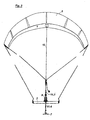
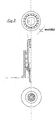
- FIG. 1 a part of a sports equipment 1 is shown schematically.
- a handle 3 is formed in the illustrated embodiment as a handlebar and has a fürgangsöfmung 3.1 in its center.
- the side of the handle 3, which is located in Fig. 1 above the handle 3, is the so-called tension side, that is, the side facing a pulling device 5 acting on the handle 3 ( Figure 3).
- the side which lies below the handle 3 is the side facing a trapeze belt, object or user 7 (FIG. 3).
- a safety device 9 is arranged on the handle 3.
- the safety device 9 deactivates the traction device 5.
- the deactivation takes place in the present embodiment by a force decoupling of the handle 3 and the user 7 acting tensile force.
- the deactivation may optionally be initiated by the user during operation, that is, the threshold may be a subjectively perceived value for each user 7.
- the manual release of the deactivation of the traction device 5 takes place as a function of a movement of the handle 3 in a direction of action of the tensile force ( Figure 4).
- the deactivation of the traction device 5 can also be triggered automatically as a function of reaching a predetermined limit value of the traction force. It is possible to set the threshold value of a tensile force before a start of operation. This can be done, for example, depending on the performance of the user 7. A criterion for the performance may be the level of training on the sports equipment but also the age of the user and his weight.
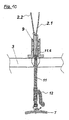
- the safety device 9 is arranged in the present embodiment on a line 11 which is guided through the opening 3.1 in the handle 3 therethrough.
- the safety device 9 is arranged on the leash 11 in the effective direction of the tensile force close to the action behind the handle 3, that is, on the tension side in Figure 1.
- Wirkenne here such proximity is meant that in the case that the object a user is equal to a maximum of one arm length of the user. The distance is adjustable. The effect proximity should be such a proximity that the handle 3 can still act with a movement on the safety device 9.
- the safety device 9 has in inner clamping element 9.1 and an outer clamping element 9.2, which are biased against each other in a direction of action of the tensile force and are arranged relative to each other against the bias relative to each other.
- the outer clamping element 9.2 has a handle side, a flange 9.3, which wraps around the outer clamping element 9.2 and the handle side forms an abutment surface for the handle 3.
- the flange 9.3 is zug turc in a sleeve portion 9.4, which abuts with an inner wall slidably on an outer wall of the inner clamping element 9.1.
- the sleeve part 9.4 has at its Werner end a smaller wall thickness than at its flange end, wherein the inner wall of the sleeve part 9.4 is stepped at the Switzerland paragraphen end, so that there is formed between the sleeve part 9.4 and the inner clamping element 9.1 a receiving space for a spring element 9.5 ,
- the spring element 9.5 is in the present case a helical spring with a uniform spring constant. It is conceivable that the spring element 9.5 has a varying spring constant, so that the spring force via an adjustment mechanism (not shown) is adjustable.
- the inner clamping element 9.1 has at its circumference on a shoulder 9.6, which closes the zugueaum formed between the sleeve part 9.4 and the clamping element 9.1 zugmen.
- the spring element 9.5 is supported on the projection 9.6 and on the step in the sleeve part 9.4, whereby the inner clamping element 9.1 and the outer clamping element 9.2 are biased against each other.
- the inner clamping element 9.1 is sleeve-shaped and has at its handle-side end a first inner annular groove 9.7.
- the inner clamping element 9.1 also has at its karmonyen end a second inner annular groove 9.8.
- the line 11 has a first karmonyes linen part 11.1, which is connected at a free end 11.2 with a pin 11.3, which sits positively in the annular groove 9.8.
- a clamping element 9.9 is attached to the Switzerland folken end of the inner clamping element 9.1, and generates a clamping voltage, such that the pin 11.3 is firmly clamped in the annular groove 9.8.
- the clamping element 11.3 may for example be a clamping nut.
- the line 11 also includes a second user-side linen portion 11.4 having at its free end 11.5 a release pin 11.6, which is identical to the pin 11.3 in the present embodiment.
- the trigger pin 11.6 sits positively in the first annular groove 9.7 and is there firmly clamped by the outer clamping element 9.2.
- the line 11 or the line parts 11.1 and 11.4 and the pins 11.3 and 11.6 are hollow or formed with a central passage in which a safety line 13 runs.
- the clamping voltage is taken away to the first annular groove 9.7 and seated therein tripping pin 11.6, so that the user-side linen part 11.4 of the line 11 slips out of the first annular groove 9.7 and dissolves from the frictional connection with the tension-side linen part 11.1.
- the tensile force is decoupled.
- the leash 11 is not divided and in the inner clamping element 9.1 only an annular groove 9.8 or 9.7 is formed in which a projection formed on the leash is firmly seated.
- the further triggering mechanism may remain identical to that described above.
- the line 11 would in this case have user side of the annular groove a linen supply, which leads in the event of a tripping to a temporary force decoupling.
- Such an embodiment can be used where such temporary power decoupling is sufficient to regain secure control over the sports equipment 1.
- FIG. 2 schematically shows a second embodiment of the safety device 9.
- the same reference numerals as in Figure 1 are used for the same components.
- the embodiment shown in Figure 2 differs only in that the outer clamping element 9.2 in a region 9.10 has a groove recess, which is preferably wedge-shaped.
- the inner clamping element 9.1 has at its periphery a recess 9.11 in which a clamping element 9.13 is pivotally mounted on a ring element 9.12.
- the trigger pin 11.6 has at its periphery an annular groove 11.7, the zuggrass forms an edge 11.8.
- the clamping wedge 9.13 abuts the edge 11.8 of the annular groove 11.7.
- the clamping wedge 9.10 turns from the locking position in the annular groove 11.7 of the pin 11.6 into the wedge-shaped groove recess 9.10 and releases the user-side linen part 11.4.
- the trigger pin 11.6 can be inserted into the inner clamping element 9.1, without the outer clamping element must be operated 9.2.
- the trigger pin 11.6 pushes the insertion of the clamping wedge 9.10 in a rotational movement upwards and laterally against a spring tongue 9.14 in the groove recess 9.10 and thus releases the opening of the inner clamping element 9.1.
- the trigger pin 9.6 inserted over the top of the clamping wedge 9.10 in the opening of the inner clamping element 9.1 presses the spring tongue 9.14 the clamping wedge 9.13 back and locks the trigger pin 11.6 in the position shown in Figure 1.
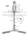
- FIG. 3 schematically shows the entire arrangement of the sports device 1 between a person (trapezoidal belt) 7 and the safety device 9.
- FIG. 5 schematically shows a development of the line 11.4 between the user 7 and the safety device 9.
- the handle 9 with its passage opening 3.1 and guided therein user-side linen part 11.4 and the safety line 13 offers the opportunity to be able to unravel it after rotation jumps or similar maneuvers freely.
- the leash 11 in the present embodiment is a so-called depower line, which in the prior art has a circular cross-section.
- the cross section may be polygonal or oval. Due to the formation of at least the Depowerleinenteils 11.4 with a non-uniform radius and in particular by the formation of the cross section in the form of a triangle, the Depowerleine 11 at a turn of the handlebar synchronously rotate with, since a rotational relative motion is hindered by positive engagement.
- a depower line 11 or such a depower part 11. 4 having a cross section which has different radii can be combined with the embodiments in FIG. 1 and FIG. 2.
- FIGS. 6 to 12 Further embodiments of the present invention and schematic illustrations are shown in FIGS. 6 to 12.
- FIG. 6 schematically shows a further embodiment of the safety device 9.
- the lower part is 9.7 of the inner clamping element 9.1 formed as a pin.
- the connection to the lower part of the tug 11.4 as "Übersch 11.6" is formed.
- a movement of the handle 3 upwards, in the direction of the tension element 5, then leads as in the embodiment in Figure 1 to the fact that the handle 3 overcomes the effect proximity to the safety device 9 and to the surface 9.4 of the flange abuts 9.3 and the outer clamping element 9.2 against the biasing force of the spring 9.5 moves upwards.
- the spring stop 9.6 of the inner clamping element 9.1 is formed as a threaded sleeve which is rotated to a thread in the upper circumference of the inner clamping element 9.1 and thus allows an individual default of the spring used 9.5.
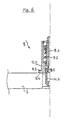
- FIG. 7 shows a further developed embodiment of the safety device 9 according to the first embodiment in FIG.
- the release sleeve 9.2 is provided in this embodiment with an expandable diameter constriction 9.14 at the top. Upon displacement of the release sleeve 9.2 on the spring stop 9.6 of the inner sleeve 9.1 upwards away both elements are locked against the bias of the spring 9.5 by engaging the diameter constriction 9.14 each other.
- the required for spreading the lower part of the inner sleeve 9.1 9.15 is created with a hole in the lower part of the outer sleeve 9.2.
- the tripping pin 11.6 is polygonal outside (not round) executed to prevent relative rotations to the inner sleeve 9.1.
- the expandable inner sleeve lower part 9.7 is divided several times according to the shape of the tripping pin 11.6. The corners of the tripping pin 11.6 can engage in the interstices of the multiply divided inner sleeve lower part 9.7.
- connection of the pulling line upper part takes place by insertion and knotting through hole 9.10 in the shaft on the upper part of the inner sleeve 9.1.
- the safety line 13 is guided through the bore 9.11 in the shaft at the top of the inner sleeve 9.1 and connected to the user-side part of the pull line in the recess at the top of the tripping pin 11.6.
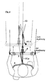
- Figure 8 shows a schematic plan view of a user who uses the sports device according to the invention and attacks with his hands on the handle, the solid lines show an active operating situation and the dashed lines show a deactive situation and motion arrows schematically represent the deactivation process.
- the functional diagram takes into account a connection with the handlebar 3 with a prior art collar or shackle release system 20 through the lines 18.
- the triggering mechanism 20 will be activated by the line 18 transmitted tensile force automatically actuated.
- the security line 13, which is centrally moved by the depower line 11, remains connected to the user 7.
- the handlebar 3 and the associated control lines 4 slip along the safety line 13 upwards.
- the stunt kite 5 falls down without pressure.
- Fig. 9 shows schematically a steering kite system which can be transmitted in the variant shown on all other described embodiments.
- the Consistor 12 in contrast to the systems known from the prior art, which use a Constant 12 for adjusting the length of the front lines 2.1 and 2.2 above the handlebar 3 on the stunt kite 5 facing side, the Consistierelement 12 in the embodiment shown here below the handlebar 3 used in the depower line 3. This creates the possibility, with the simultaneous use of the safety device 9, one of the front lines 2.1 as a continuous safety line with the releasable Depowerleinenunterteil 11 to connect.
- the use of an additional safety line 13 in this embodiment is not necessary. If the safety device 9 is triggered, then the handlebar 3 with the control lines 4 fastened thereto and the safety device 9 with the second front line 2.2 fastened to its upper part slide on the front line 2.1 running in the direction of the safety line of the steering kite 5. The only used by the continuous leash used as a continuous line 2.1 2.1 with the user 7 Steering kite 5 then falls down without pressure.
- Figure 10 shows a detailed diagram of the embodiment of Figure 9 with the connection of the front line 2.2 to the upper part of the inner clamping element 9.1 of the safety device 9 and the front line 2.1 as a continuous safety line with connection to the tripping pin 9.7 of the depower line 11 and the integration of the length adjustment 12 of the depower line below the handlebar 3.
- FIG. 11 schematically shows a further, further developed embodiment of the safety device 9.
- an elastomeric spring 9.5 is used in this embodiment, which can be adapted in various Shore hardnesses to individual needs of the release force.
- the replaceable elastomer spring 9.5 is stretched between release sleeve 9.2 and inner sleeve 9.1.
- Release sleeve 9.2 and inner sleeve 9.1 are assembled by means of an outer diameter extension at the lower end of the inner sleeve 9.1 9.7.
- the expandable lower part 9.7 of the inner sleeve 9.1 is compressed with disassembled trigger pin 11.6.
- the spring 9.5 and the outer sleeve 9.2 are pushed over the compressed inner sleeve lower part 9.7.
- a front line leads a short connecting line through a hole 9.11 in the upper lid he inner sleeve 9.1 and is secured with a knot against slipping.
- the other front line is called a continuous safety line through the second Bore in the upper cover of the inner sleeve 9.1 out and tied at the end of Depowerleinenunterteils 11 in the recess of the tripping pin 11.8.
- the recess for receiving the expandable inner sleeve lower part in the lower part of the outer sleeve is, as already described with reference to FIG 7, executed.
- the polygonal, ovale placed. not round shape of the tripping pin 11.6 with adapted form of the expandable lower part 9.7 of the inner sleeve 9.1 is carried out according to the descriptions with reference to FIG.
- FIG. 12 shows a further embodiment of the safety device 9, which is similar to the described embodiment according to FIG.
- the elastomeric spring used is 9.5 bonded to the bottom and top with centrally pierced discs 9.16.
- the spring element consisting of elastomer spring 9.5 and glued discs 9.16, screwed through the upper cover of the inner sleeve 9.1 with the inner sleeve 9.1.
- the second disc 9.16 on the lower part of the elastomeric spring 9.5 is screwed to the release sleeve 9.2.
- the embodiment shown here takes into account the use of an additional safety line 13, which is guided through the hole 9.11 in the lid at the top of the inner sleeve 9.1 and connected to the end of Depowerleinenunterteils 11 in the recess of the tripping pin 11.6.
- the upper part of the tug, to which the length adjuster 12 adjoins on the side facing the steer kite 5, is connected to a stirrup which is fastened to the upper side of the cover of the inner sleeve 9.1.
Claims (18)
- Appareil de sport comportant une poignée-barre servant à retenir et à piloter l'appareil de sport, un dispositif de traction qui à l'état actif est relié de manière active à l'utilisateur par l'intermédiaire d'une ligne de traction et exerce une force de traction sur l'utilisateur, ainsi qu'un dispositif de sécurité servant à découpler la force de traction agissant sur la ligne de traction, l'utilisateur tenant la poignée-barre à l'état actif,
caractérisé en ce que le dispositif de sécurité (9) est disposé côté traction sur la poignée-barre (3), à proximité effective de l'utilisateur (7), et, à l'état actif, il peut être déclenché par un mouvement de la poignée-barre (3) dans la direction d'action de la force de traction et, en cas de déclenchement, il découple la force de traction agissant sur ligne de traction (11). - Appareil de sport selon la revendication 1,
caractérisé en ce que le dispositif de sécurité (9) est disposé sur la poignée-barre (3) et sur la ligne de traction (11) dans la direction d'action de la force de traction. - Appareil de sport selon la revendication 1 ou 2,
caractérisé en ce que la ligne de traction (11) passe dans la poignée-barre (3). - Appareil de sport selon l'une des revendications 1 à 3,
caractérisé en ce que le dispositif de sécurité (9) comporte un élément de serrage intérieur (9.1) sur lequel est monté, extérieurement, un élément de serrage extérieur (9.2) pouvant coulisser axialement d'une position de blocage à une position de libération à l'encontre d'une force de précontrainte. - Appareil de sport selon la revendication 4,
caractérisé en ce que, en fonctionnement, l'élément de serrage extérieur (9.2) exerce, de manière sensiblement transversale à la direction d'action de la force de traction, une tension sur l'élément de serrage intérieur (9.1) de telle sorte que la ligne de traction (11) soit solidement enserrée dans l'élément de serrage intérieur (9.1). - Appareil de sport selon la revendication 5,
caractérisé en ce que le mouvement de la poignée-barre (3) dans la direction d'action de la force de traction provoque un déplacement de l'élément de serrage extérieur (9.2) à l'encontre de la force de précontrainte et relativement à l'élément de serrage intérieur (9.1) et met un terme au solide enserrement de la ligne de traction (11) dans l'élément de serrage intérieur (9.1). - Appareil de sport selon l'une des revendications 1 à 6,
caractérisé en ce que la ligne de traction (11) comporte une première partie de ligne (11.1) qui est disposée entre le dispositif de sécurité (9) et le dispositif de traction (5) et une seconde partie de ligne (11.4) qui est disposée entre l'utilisateur (7) et le- dispositif de sécurité (9), les deux parties de ligne (11.1, 11.4) étant reliées, en fonctionnement, dans le dispositif de sécurité (9). - Appareil de sport selon la revendication 7,
caractérisé en ce que la première partie de ligne (11.1) est solidement enserrée au niveau d'une extrémité de l'élément de serrage intérieur (9.1) située côté traction et en ce que la seconde partie de ligne (11.4) est solidement enserrée au niveau d'une extrémité de l'élément de serrage intérieur (9.1) située côté poignée-barre, transversalement à la direction d'action de la force de traction, du fait de l'effet de serrage de l'élément de serrage extérieur (9.2). - Appareil de sport selon la revendication 8,
caractérisé en ce que le mouvement de la poignée-barre (3) dans la direction d'action de la force de traction provoque un déplacement de l'élément de serrage extérieur (9.2) à l'encontre de la force de précontrainte, relativement à l'élément de serrage intérieur (9.1), et met un terme au solide enserrement de la seconde partie de ligne (11.4) dans l'élément de serrage intérieur (9.1). - Appareil de sport selon l'une des revendications 1 à 9,
caractérisé en ce que l'on fait passer la seconde partie de ligne (11.4) de la ligne de traction (11) à travers la poignée-barre (3). - Appareil de sport selon l'une des revendications 5 à 10,
caractérisé en ce que la ligne de traction (11) est une ligne de gestion de puissance. - Appareil de sport selon l'une des revendications précédentes,
caractérisé en ce que la poignée-barre (3) est une barre de direction. - Appareil de sport selon l'une des revendications précédentes,
caractérisé en ce que le dispositif de traction (5) est une aile volante. - Appareil de sport selon la revendication 11,
caractérisé en ce que-la ligne de traction (11) réalisée sous forme de ligne de gestion de puissance est creuse et a une section ayant différents rayons. - Appareil de sport selon la revendication 14,
caractérisé en ce que l'on fait passer une ligne de sécurité (13) à travers la poignée-barre (3) dans la ligne de traction (11) réalisée sous forme de ligne de gestion de puissance. - Appareil de sport selon la revendication 14 ou 15,
caractérisé en ce que la section de la ligne de traction (11) réalisée sous forme de ligne de gestion de puissance est polygonale. - Appareil de sport selon les revendications 14 à 16,
caractérisé en ce que la section de la ligne de- traction réalisée sous forme de ligne de gestion de puissance (11) est triangulaire. - Appareil de sport selon les revendications 14 et 17,
caractérisé en ce que la section de la ligne de traction réalisée sous forme de ligne de gestion de puissance (11) est ovale.
Applications Claiming Priority (7)
| Application Number | Priority Date | Filing Date | Title |
|---|---|---|---|
| DE10258637A DE10258637C5 (de) | 2002-12-13 | 2002-12-13 | Sportgerät mit einer Sicherheitseinrichtung |
| DE10258637 | 2002-12-13 | ||
| DE20302460U | 2003-02-15 | ||
| DE20302460U DE20302460U1 (de) | 2002-12-13 | 2003-02-15 | Sportgerät mit einer Sicherheitseinrichtung |
| DE20303089U | 2003-02-26 | ||
| DE20303089U DE20303089U1 (de) | 2002-12-13 | 2003-02-26 | Sportgerät mit einer Sicherheitseinrichtung |
| PCT/DE2003/004200 WO2004054659A2 (fr) | 2002-12-13 | 2003-12-12 | Appareil de sport pourvu d'un dispositif de securite |
Publications (3)
| Publication Number | Publication Date |
|---|---|
| EP1569726A2 EP1569726A2 (fr) | 2005-09-07 |
| EP1569726B1 true EP1569726B1 (fr) | 2006-11-02 |
| EP1569726B2 EP1569726B2 (fr) | 2012-08-15 |
Family
ID=32600537
Family Applications (1)
| Application Number | Title | Priority Date | Filing Date |
|---|---|---|---|
| EP03785593A Expired - Lifetime EP1569726B2 (fr) | 2002-12-13 | 2003-12-12 | Appareil de sport pourvu d'un dispositif de securite |
Country Status (5)
| Country | Link |
|---|---|
| EP (1) | EP1569726B2 (fr) |
| AT (1) | ATE344096T1 (fr) |
| DE (1) | DE50305607D1 (fr) |
| ES (1) | ES2276141T5 (fr) |
| WO (1) | WO2004054659A2 (fr) |
Cited By (2)
| Publication number | Priority date | Publication date | Assignee | Title |
|---|---|---|---|---|
| DE102010053320B3 (de) * | 2010-12-01 | 2012-06-14 | Christian OTTERBACH | Trainingsgerät für Kitesportarten |
| US8814098B2 (en) | 2010-06-17 | 2014-08-26 | Neil Pryde Limited | Control system for a traction wing |
Families Citing this family (2)
| Publication number | Priority date | Publication date | Assignee | Title |
|---|---|---|---|---|
| FR2875788B1 (fr) * | 2004-09-24 | 2006-12-15 | Ronan Saliou | Cerf-volant de traction pour sport de glisse |
| IT1396531B1 (it) * | 2009-10-22 | 2012-12-14 | Flaccomio Nardi Dei | Dispositivo per lo sgancio automatico di una linea, in particolare una linea di collegemento di una vela da kite surfing al corpo del surfista |
Family Cites Families (6)
| Publication number | Priority date | Publication date | Assignee | Title |
|---|---|---|---|---|
| US5816636A (en) * | 1997-06-24 | 1998-10-06 | Gibson; Daniel R. | Self-releasing log choker |
| DE10047452A1 (de) * | 2000-09-26 | 2002-01-03 | Peter Stiewe | Bar (Steuerstange des Drachens) mit arretierbarer Depowereinrichtung |
| US6581879B2 (en) † | 2000-11-16 | 2003-06-24 | John D. Bellacera | Kite control systems |
| DE20107925U1 (de) * | 2001-05-10 | 2002-01-24 | Flysurfer Gmbh | Leinensystem zum Steuern eines Kites |
| DE20209515U1 (de) † | 2002-06-19 | 2002-10-17 | Huber Christian | Passives Sicherheitssystem für 4-Leiner Kites |
| DE10262138B4 (de) * | 2002-12-13 | 2007-06-21 | Dirk Schiffmann | Sportgerät mit Depowerleine |
-
2003
- 2003-12-12 ES ES03785593T patent/ES2276141T5/es not_active Expired - Lifetime
- 2003-12-12 EP EP03785593A patent/EP1569726B2/fr not_active Expired - Lifetime
- 2003-12-12 WO PCT/DE2003/004200 patent/WO2004054659A2/fr active IP Right Grant
- 2003-12-12 AT AT03785593T patent/ATE344096T1/de active
- 2003-12-12 DE DE50305607T patent/DE50305607D1/de not_active Expired - Lifetime
Cited By (2)
| Publication number | Priority date | Publication date | Assignee | Title |
|---|---|---|---|---|
| US8814098B2 (en) | 2010-06-17 | 2014-08-26 | Neil Pryde Limited | Control system for a traction wing |
| DE102010053320B3 (de) * | 2010-12-01 | 2012-06-14 | Christian OTTERBACH | Trainingsgerät für Kitesportarten |
Also Published As
| Publication number | Publication date |
|---|---|
| WO2004054659A3 (fr) | 2004-08-19 |
| EP1569726A2 (fr) | 2005-09-07 |
| WO2004054659B1 (fr) | 2004-11-04 |
| ATE344096T1 (de) | 2006-11-15 |
| ES2276141T5 (es) | 2012-10-30 |
| ES2276141T3 (es) | 2007-06-16 |
| WO2004054659A2 (fr) | 2004-07-01 |
| DE50305607D1 (de) | 2006-12-14 |
| EP1569726B2 (fr) | 2012-08-15 |
Similar Documents
| Publication | Publication Date | Title |
|---|---|---|
| CH615833A5 (fr) | ||
| EP1569726B1 (fr) | Appareil de sport pourvu d'un dispositif de securite | |
| DE10262138B4 (de) | Sportgerät mit Depowerleine | |
| DE102016103532B3 (de) | Steuerungs- und Zugkraftübertragungseinrichtung für einen Lenkdrachen | |
| DE10258637B4 (de) | Sportgerät mit einer Sicherheitseinrichtung | |
| DE10304072A1 (de) | Sportgerät mit zwei Lenkleinen und einer Sicherheitseinrichtung | |
| EP1516810B1 (fr) | Dispositif de contrôle pour une aile de traction | |
| DE202004006143U1 (de) | Trapez | |
| DE102010021462B4 (de) | Sicherheitseinrichtung für einen Kite und Kite | |
| DE202009002826U1 (de) | Sicherheitseinrichtung an der Zugleine großer Lenkdrachen | |
| DE20315464U1 (de) | Steuerstange für Kiteschirme | |
| DE2115403C3 (de) | Seilspannungsregler fur Steuer seile | |
| DE10242455B4 (de) | Verbindungselement eines lenkbaren Drachens | |
| DE202019101286U1 (de) | Safety-Leash und Sicherheitseinrichtung mit einer Safety-Leash | |
| DE2916643A1 (de) | Trapezgurt fuer windsurfbretter | |
| DE202019103607U1 (de) | Leinensystem eines Lenkdrachens | |
| WO2005023631A2 (fr) | Systeme de securite ameliore pour cerf-volant a quatre suspentes | |
| DE202006019043U1 (de) | Sicherheitseinrichtung für einen Lenkdrachen-Kite | |
| DE102006005620A1 (de) | Lenkdrachen-Kite mit einer Stützleine | |
| DE202009010309U1 (de) | Ausdrehbare Sicherheitsleine an großen Lenkdrachen | |
| DE202010009294U1 (de) | Magnetvorrichtung zur Lagerung der Auslösehülse an einer Sicherheitseinrichtung großer Lenkdrachen | |
| DE202012003062U1 (de) | Loopverbindung an der Zugleine eines Lenkdrachen | |
| DE202011103240U1 (de) | Verbindung eines Strangs der Zugleine großer Lenkdrachen mit einer Flugleine | |
| DE4230033C2 (de) | Variable Sicherheits-Trapeztampenbefestigung für Windsurfboards | |
| DE3914210A1 (de) | Vorrichtung zur befestigung an einem trapeztampen |
Legal Events
| Date | Code | Title | Description |
|---|---|---|---|
| PUAI | Public reference made under article 153(3) epc to a published international application that has entered the european phase |
Free format text: ORIGINAL CODE: 0009012 |
|
| 17P | Request for examination filed |
Effective date: 20050428 |
|
| AK | Designated contracting states |
Kind code of ref document: A2 Designated state(s): AT BE BG CH CY CZ DE DK EE ES FI FR GB GR HU IE IT LI LU MC NL PT RO SE SI SK TR |
|
| AX | Request for extension of the european patent |
Extension state: AL LT LV MK |
|
| DAX | Request for extension of the european patent (deleted) | ||
| GRAP | Despatch of communication of intention to grant a patent |
Free format text: ORIGINAL CODE: EPIDOSNIGR1 |
|
| GRAS | Grant fee paid |
Free format text: ORIGINAL CODE: EPIDOSNIGR3 |
|
| GRAA | (expected) grant |
Free format text: ORIGINAL CODE: 0009210 |
|
| AK | Designated contracting states |
Kind code of ref document: B1 Designated state(s): AT BE BG CH CY CZ DE DK EE ES FI FR GB GR HU IE IT LI LU MC NL PT RO SE SI SK TR |
|
| PG25 | Lapsed in a contracting state [announced via postgrant information from national office to epo] |
Ref country code: FI Free format text: LAPSE BECAUSE OF FAILURE TO SUBMIT A TRANSLATION OF THE DESCRIPTION OR TO PAY THE FEE WITHIN THE PRESCRIBED TIME-LIMIT Effective date: 20061102 Ref country code: SI Free format text: LAPSE BECAUSE OF FAILURE TO SUBMIT A TRANSLATION OF THE DESCRIPTION OR TO PAY THE FEE WITHIN THE PRESCRIBED TIME-LIMIT Effective date: 20061102 Ref country code: CZ Free format text: LAPSE BECAUSE OF FAILURE TO SUBMIT A TRANSLATION OF THE DESCRIPTION OR TO PAY THE FEE WITHIN THE PRESCRIBED TIME-LIMIT Effective date: 20061102 Ref country code: IE Free format text: LAPSE BECAUSE OF FAILURE TO SUBMIT A TRANSLATION OF THE DESCRIPTION OR TO PAY THE FEE WITHIN THE PRESCRIBED TIME-LIMIT Effective date: 20061102 Ref country code: SK Free format text: LAPSE BECAUSE OF FAILURE TO SUBMIT A TRANSLATION OF THE DESCRIPTION OR TO PAY THE FEE WITHIN THE PRESCRIBED TIME-LIMIT Effective date: 20061102 Ref country code: RO Free format text: LAPSE BECAUSE OF FAILURE TO SUBMIT A TRANSLATION OF THE DESCRIPTION OR TO PAY THE FEE WITHIN THE PRESCRIBED TIME-LIMIT Effective date: 20061102 |
|
| REG | Reference to a national code |
Ref country code: GB Ref legal event code: FG4D Free format text: NOT ENGLISH |
|
| REG | Reference to a national code |
Ref country code: IE Ref legal event code: FG4D Free format text: LANGUAGE OF EP DOCUMENT: GERMAN |
|
| REG | Reference to a national code |
Ref country code: CH Ref legal event code: EP |
|
| REF | Corresponds to: |
Ref document number: 50305607 Country of ref document: DE Date of ref document: 20061214 Kind code of ref document: P |
|
| PG25 | Lapsed in a contracting state [announced via postgrant information from national office to epo] |
Ref country code: MC Free format text: LAPSE BECAUSE OF NON-PAYMENT OF DUE FEES Effective date: 20061231 |
|
| PG25 | Lapsed in a contracting state [announced via postgrant information from national office to epo] |
Ref country code: DK Free format text: LAPSE BECAUSE OF FAILURE TO SUBMIT A TRANSLATION OF THE DESCRIPTION OR TO PAY THE FEE WITHIN THE PRESCRIBED TIME-LIMIT Effective date: 20070202 Ref country code: SE Free format text: LAPSE BECAUSE OF FAILURE TO SUBMIT A TRANSLATION OF THE DESCRIPTION OR TO PAY THE FEE WITHIN THE PRESCRIBED TIME-LIMIT Effective date: 20070202 Ref country code: BG Free format text: LAPSE BECAUSE OF FAILURE TO SUBMIT A TRANSLATION OF THE DESCRIPTION OR TO PAY THE FEE WITHIN THE PRESCRIBED TIME-LIMIT Effective date: 20070202 |
|
| PG25 | Lapsed in a contracting state [announced via postgrant information from national office to epo] |
Ref country code: PT Free format text: LAPSE BECAUSE OF FAILURE TO SUBMIT A TRANSLATION OF THE DESCRIPTION OR TO PAY THE FEE WITHIN THE PRESCRIBED TIME-LIMIT Effective date: 20070402 |
|
| ET | Fr: translation filed | ||
| REG | Reference to a national code |
Ref country code: ES Ref legal event code: FG2A Ref document number: 2276141 Country of ref document: ES Kind code of ref document: T3 |
|
| REG | Reference to a national code |
Ref country code: IE Ref legal event code: FD4D |
|
| PLBE | No opposition filed within time limit |
Free format text: ORIGINAL CODE: 0009261 |
|
| PLAA | Information modified related to event that no opposition was filed |
Free format text: ORIGINAL CODE: 0009299DELT |
|
| PLBI | Opposition filed |
Free format text: ORIGINAL CODE: 0009260 |
|
| 26N | No opposition filed |
Effective date: 20070803 |
|
| PLAX | Notice of opposition and request to file observation + time limit sent |
Free format text: ORIGINAL CODE: EPIDOSNOBS2 |
|
| 26 | Opposition filed |
Opponent name: NEIL PRYDE LIMITED Effective date: 20070802 |
|
| D26N | No opposition filed (deleted) | ||
| NLR1 | Nl: opposition has been filed with the epo |
Opponent name: NEIL PRYDE LIMITED |
|
| PLBB | Reply of patent proprietor to notice(s) of opposition received |
Free format text: ORIGINAL CODE: EPIDOSNOBS3 |
|
| PG25 | Lapsed in a contracting state [announced via postgrant information from national office to epo] |
Ref country code: GR Free format text: LAPSE BECAUSE OF FAILURE TO SUBMIT A TRANSLATION OF THE DESCRIPTION OR TO PAY THE FEE WITHIN THE PRESCRIBED TIME-LIMIT Effective date: 20070203 |
|
| PG25 | Lapsed in a contracting state [announced via postgrant information from national office to epo] |
Ref country code: EE Free format text: LAPSE BECAUSE OF FAILURE TO SUBMIT A TRANSLATION OF THE DESCRIPTION OR TO PAY THE FEE WITHIN THE PRESCRIBED TIME-LIMIT Effective date: 20061102 |
|
| PG25 | Lapsed in a contracting state [announced via postgrant information from national office to epo] |
Ref country code: HU Free format text: LAPSE BECAUSE OF FAILURE TO SUBMIT A TRANSLATION OF THE DESCRIPTION OR TO PAY THE FEE WITHIN THE PRESCRIBED TIME-LIMIT Effective date: 20070503 Ref country code: TR Free format text: LAPSE BECAUSE OF FAILURE TO SUBMIT A TRANSLATION OF THE DESCRIPTION OR TO PAY THE FEE WITHIN THE PRESCRIBED TIME-LIMIT Effective date: 20061102 Ref country code: LU Free format text: LAPSE BECAUSE OF NON-PAYMENT OF DUE FEES Effective date: 20061212 |
|
| REG | Reference to a national code |
Ref country code: CH Ref legal event code: PL |
|
| PG25 | Lapsed in a contracting state [announced via postgrant information from national office to epo] |
Ref country code: LI Free format text: LAPSE BECAUSE OF NON-PAYMENT OF DUE FEES Effective date: 20071231 Ref country code: CH Free format text: LAPSE BECAUSE OF NON-PAYMENT OF DUE FEES Effective date: 20071231 |
|
| PG25 | Lapsed in a contracting state [announced via postgrant information from national office to epo] |
Ref country code: CY Free format text: LAPSE BECAUSE OF FAILURE TO SUBMIT A TRANSLATION OF THE DESCRIPTION OR TO PAY THE FEE WITHIN THE PRESCRIBED TIME-LIMIT Effective date: 20061102 |
|
| PLCK | Communication despatched that opposition was rejected |
Free format text: ORIGINAL CODE: EPIDOSNREJ1 |
|
| APBM | Appeal reference recorded |
Free format text: ORIGINAL CODE: EPIDOSNREFNO |
|
| APBP | Date of receipt of notice of appeal recorded |
Free format text: ORIGINAL CODE: EPIDOSNNOA2O |
|
| APAH | Appeal reference modified |
Free format text: ORIGINAL CODE: EPIDOSCREFNO |
|
| APBQ | Date of receipt of statement of grounds of appeal recorded |
Free format text: ORIGINAL CODE: EPIDOSNNOA3O |
|
| APBU | Appeal procedure closed |
Free format text: ORIGINAL CODE: EPIDOSNNOA9O |
|
| PLAY | Examination report in opposition despatched + time limit |
Free format text: ORIGINAL CODE: EPIDOSNORE2 |
|
| PGFP | Annual fee paid to national office [announced via postgrant information from national office to epo] |
Ref country code: IT Payment date: 20110630 Year of fee payment: 8 |
|
| PUAH | Patent maintained in amended form |
Free format text: ORIGINAL CODE: 0009272 |
|
| STAA | Information on the status of an ep patent application or granted ep patent |
Free format text: STATUS: PATENT MAINTAINED AS AMENDED |
|
| 27A | Patent maintained in amended form |
Effective date: 20120815 |
|
| AK | Designated contracting states |
Kind code of ref document: B2 Designated state(s): AT BE BG CH CY CZ DE DK EE ES FI FR GB GR HU IE IT LI LU MC NL PT RO SE SI SK TR |
|
| REG | Reference to a national code |
Ref country code: DE Ref legal event code: R102 Ref document number: 50305607 Country of ref document: DE Effective date: 20120815 |
|
| REG | Reference to a national code |
Ref country code: ES Ref legal event code: DC2A Ref document number: 2276141 Country of ref document: ES Kind code of ref document: T5 Effective date: 20121030 |
|
| REG | Reference to a national code |
Ref country code: NL Ref legal event code: T3 |
|
| PG25 | Lapsed in a contracting state [announced via postgrant information from national office to epo] |
Ref country code: IT Free format text: LAPSE BECAUSE OF NON-PAYMENT OF DUE FEES Effective date: 20111212 |
|
| REG | Reference to a national code |
Ref country code: ES Ref legal event code: FD2A Effective date: 20130703 |
|
| PG25 | Lapsed in a contracting state [announced via postgrant information from national office to epo] |
Ref country code: ES Free format text: LAPSE BECAUSE OF NON-PAYMENT OF DUE FEES Effective date: 20111213 |
|
| REG | Reference to a national code |
Ref country code: FR Ref legal event code: PLFP Year of fee payment: 13 |
|
| REG | Reference to a national code |
Ref country code: FR Ref legal event code: PLFP Year of fee payment: 14 |
|
| REG | Reference to a national code |
Ref country code: FR Ref legal event code: PLFP Year of fee payment: 15 |
|
| PGFP | Annual fee paid to national office [announced via postgrant information from national office to epo] |
Ref country code: BE Payment date: 20171219 Year of fee payment: 15 Ref country code: GB Payment date: 20171221 Year of fee payment: 15 |
|
| PGFP | Annual fee paid to national office [announced via postgrant information from national office to epo] |
Ref country code: ES Payment date: 20190103 Year of fee payment: 16 |
|
| GBPC | Gb: european patent ceased through non-payment of renewal fee |
Effective date: 20181212 |
|
| REG | Reference to a national code |
Ref country code: BE Ref legal event code: MM Effective date: 20181231 |
|
| PG25 | Lapsed in a contracting state [announced via postgrant information from national office to epo] |
Ref country code: BE Free format text: LAPSE BECAUSE OF NON-PAYMENT OF DUE FEES Effective date: 20181231 |
|
| PG25 | Lapsed in a contracting state [announced via postgrant information from national office to epo] |
Ref country code: GB Free format text: LAPSE BECAUSE OF NON-PAYMENT OF DUE FEES Effective date: 20181212 |
|
| PGFP | Annual fee paid to national office [announced via postgrant information from national office to epo] |
Ref country code: FR Payment date: 20191219 Year of fee payment: 17 |
|
| PGFP | Annual fee paid to national office [announced via postgrant information from national office to epo] |
Ref country code: AT Payment date: 20191218 Year of fee payment: 17 |
|
| PGFP | Annual fee paid to national office [announced via postgrant information from national office to epo] |
Ref country code: DE Payment date: 20200122 Year of fee payment: 17 |
|
| REG | Reference to a national code |
Ref country code: NL Ref legal event code: MM Effective date: 20200101 |
|
| PG25 | Lapsed in a contracting state [announced via postgrant information from national office to epo] |
Ref country code: NL Free format text: LAPSE BECAUSE OF NON-PAYMENT OF DUE FEES Effective date: 20200101 |
|
| REG | Reference to a national code |
Ref country code: DE Ref legal event code: R119 Ref document number: 50305607 Country of ref document: DE |
|
| REG | Reference to a national code |
Ref country code: AT Ref legal event code: MM01 Ref document number: 344096 Country of ref document: AT Kind code of ref document: T Effective date: 20201212 |
|
| PG25 | Lapsed in a contracting state [announced via postgrant information from national office to epo] |
Ref country code: FR Free format text: LAPSE BECAUSE OF NON-PAYMENT OF DUE FEES Effective date: 20201231 Ref country code: AT Free format text: LAPSE BECAUSE OF NON-PAYMENT OF DUE FEES Effective date: 20201212 |
|
| PG25 | Lapsed in a contracting state [announced via postgrant information from national office to epo] |
Ref country code: DE Free format text: LAPSE BECAUSE OF NON-PAYMENT OF DUE FEES Effective date: 20210701 |