EP1569726B1 - Sporting apparatus comprising a safety mechanism - Google Patents
Sporting apparatus comprising a safety mechanism Download PDFInfo
- Publication number
- EP1569726B1 EP1569726B1 EP03785593A EP03785593A EP1569726B1 EP 1569726 B1 EP1569726 B1 EP 1569726B1 EP 03785593 A EP03785593 A EP 03785593A EP 03785593 A EP03785593 A EP 03785593A EP 1569726 B1 EP1569726 B1 EP 1569726B1
- Authority
- EP
- European Patent Office
- Prior art keywords
- cord
- handle
- sports device
- pull
- tensioning element
- Prior art date
- Legal status (The legal status is an assumption and is not a legal conclusion. Google has not performed a legal analysis and makes no representation as to the accuracy of the status listed.)
- Expired - Lifetime
Links
- 230000007246 mechanism Effects 0.000 title claims description 15
- 230000033001 locomotion Effects 0.000 claims description 20
- 230000000694 effects Effects 0.000 claims description 5
- 230000009849 deactivation Effects 0.000 description 9
- 230000009471 action Effects 0.000 description 7
- 210000004247 hand Anatomy 0.000 description 5
- 230000008901 benefit Effects 0.000 description 3
- 230000001960 triggered effect Effects 0.000 description 3
- 230000015572 biosynthetic process Effects 0.000 description 2
- 238000010586 diagram Methods 0.000 description 2
- 229920001971 elastomer Polymers 0.000 description 2
- 239000000806 elastomer Substances 0.000 description 2
- 238000003780 insertion Methods 0.000 description 2
- 230000037431 insertion Effects 0.000 description 2
- 238000000034 method Methods 0.000 description 2
- 230000008569 process Effects 0.000 description 2
- 230000001105 regulatory effect Effects 0.000 description 2
- 230000007480 spreading Effects 0.000 description 2
- 230000005540 biological transmission Effects 0.000 description 1
- 230000001276 controlling effect Effects 0.000 description 1
- 230000001419 dependent effect Effects 0.000 description 1
- 238000006073 displacement reaction Methods 0.000 description 1
- 230000005489 elastic deformation Effects 0.000 description 1
- 235000019589 hardness Nutrition 0.000 description 1
- 230000010354 integration Effects 0.000 description 1
- 230000009191 jumping Effects 0.000 description 1
- 230000004044 response Effects 0.000 description 1
- 150000003839 salts Chemical class 0.000 description 1
- 239000004576 sand Substances 0.000 description 1
- XLYOFNOQVPJJNP-UHFFFAOYSA-N water Substances O XLYOFNOQVPJJNP-UHFFFAOYSA-N 0.000 description 1
- 210000000707 wrist Anatomy 0.000 description 1
Images


Classifications
-
- B—PERFORMING OPERATIONS; TRANSPORTING
- B63—SHIPS OR OTHER WATERBORNE VESSELS; RELATED EQUIPMENT
- B63H—MARINE PROPULSION OR STEERING
- B63H8/00—Sail or rigging arrangements specially adapted for water sports boards, e.g. for windsurfing or kitesurfing
- B63H8/10—Kite-sails; Kite-wings; Control thereof; Safety means therefor
- B63H8/16—Control arrangements, e.g. control bars or control lines
-
- B—PERFORMING OPERATIONS; TRANSPORTING
- B63—SHIPS OR OTHER WATERBORNE VESSELS; RELATED EQUIPMENT
- B63H—MARINE PROPULSION OR STEERING
- B63H8/00—Sail or rigging arrangements specially adapted for water sports boards, e.g. for windsurfing or kitesurfing
- B63H8/10—Kite-sails; Kite-wings; Control thereof; Safety means therefor
- B63H8/18—Arrangements for connecting the user to a kite-sail; Kite-safety means, e.g. chicken loops, safety leashes or quick release mechanisms
-
- B—PERFORMING OPERATIONS; TRANSPORTING
- B63—SHIPS OR OTHER WATERBORNE VESSELS; RELATED EQUIPMENT
- B63H—MARINE PROPULSION OR STEERING
- B63H8/00—Sail or rigging arrangements specially adapted for water sports boards, e.g. for windsurfing or kitesurfing
- B63H8/50—Accessories, e.g. repair kits or kite launching aids
- B63H8/56—Devices to distribute the user's load, e.g. harnesses
Definitions
- the present invention relates to a sports device with a handle for holding and controlling the sports equipment and with a pulling device, which is operatively connected to the handle and exerts a pulling force on the handle and a coupled object in an active state.
- Such a sports equipment is known in the art e.g. as a stunt kite, parachute, paraglider, kite or even as a pleasure craft that waterskiing.
- Such a sports equipment is known from DE-U-20 209 515.
- kite kites are used to power kite (surf) boards, snowkiteboards, skis, buggies and other sports vehicles.
- the kite is equipped with several lines which serve to control the direction of air movement and speed as well as the regulation of the angle of attack, i.e. the angle of flow.
- the steering lines are directly connected to a handle or a handlebar or bar.
- the lines for regulating the angle of attack are summarized above the bar to a tug or depower line.
- This depower line is passed through an opening in the center of the bar, or through a sleeve fixed centrally on the outside of the bar, and attached to the receptacle, i.e., a hook, eyelet, shackle, or the like, of a trapezoidal belt tied around a user's body.
- a sleeve fixed centrally on the outside of the bar, and attached to the receptacle, i.e., a hook, eyelet, shackle, or the like, of a trapezoidal belt tied around a user's body.
- the user connects a safety line to one of the flying lines, e.g. on a harness hook, a shackle or a wrist, or with the brake lines, as in a soft kite. If the user breaks away from the bar and the depower line, he remains connected to the kite which is now without power
- the stunt kite generates buoyancy forces due to wind flow according to the wing principle, which are transmitted as pulling forces over the lines to the bar and to the user.
- the Buoyancy-related traction forces can be regulated by relative length changes of the depower and stern lines.
- the control lines are relieved, and tilting or deconstructing the kite profile reduces lift and reduces pulling forces.
- An additional dynamic buoyancy is created when the kite is put into a proper motion, i.e. a flight on a circular path with a line-length radius, by unilateral line pulling left or right.
- a proper motion i.e. a flight on a circular path with a line-length radius
- the forces acting on the user increase. At the start of the driving movement or to increase the driving speed, such a control pulse is intentionally generated.
- the object of the invention is therefore to continue to form a sports equipment of the type mentioned in that a caused by a loss of control induced dangerous situation can be completed reliably and quickly.
- a safety device is arranged in the vicinity of the handle, which deactivates the traction device upon reaching a threshold value of the tensile force.
- the depower line has a cross section with different radii and is performed by a safety device which is arranged in the vicinity of the handle and the traction device deactivated upon reaching a threshold value of the tensile force.
- Another advantage of the present invention according to claim 2 is that the deactivation of the pulling device in response to a movement of the handle in a direction of action of the tensile force takes place. The user must move to deactivate only the handle in the direction of action of the pulling force of the pulling device to operate the trigger mechanism and disable the pulling device.
- deactivation of the traction device can also be done automatically by the safety device triggers upon reaching a predetermined limit and deactivated the towing device. This may be provided as an alternative or in addition to the movement-dependent deactivation, for example to enable a safer training.
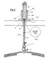
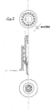
- FIG. 1 a part of a sports equipment 1 is shown schematically.
- a handle 3 is formed in the illustrated embodiment as a handlebar and has a fürgangsöfmung 3.1 in its center.
- the side of the handle 3, which is located in Fig. 1 above the handle 3, is the so-called tension side, that is, the side facing a pulling device 5 acting on the handle 3 ( Figure 3).
- the side which lies below the handle 3 is the side facing a trapeze belt, object or user 7 (FIG. 3).
- a safety device 9 is arranged on the handle 3.
- the safety device 9 deactivates the traction device 5.
- the deactivation takes place in the present embodiment by a force decoupling of the handle 3 and the user 7 acting tensile force.
- the deactivation may optionally be initiated by the user during operation, that is, the threshold may be a subjectively perceived value for each user 7.
- the manual release of the deactivation of the traction device 5 takes place as a function of a movement of the handle 3 in a direction of action of the tensile force ( Figure 4).
- the deactivation of the traction device 5 can also be triggered automatically as a function of reaching a predetermined limit value of the traction force. It is possible to set the threshold value of a tensile force before a start of operation. This can be done, for example, depending on the performance of the user 7. A criterion for the performance may be the level of training on the sports equipment but also the age of the user and his weight.
- the safety device 9 is arranged in the present embodiment on a line 11 which is guided through the opening 3.1 in the handle 3 therethrough.
- the safety device 9 is arranged on the leash 11 in the effective direction of the tensile force close to the action behind the handle 3, that is, on the tension side in Figure 1.
- Wirkenne here such proximity is meant that in the case that the object a user is equal to a maximum of one arm length of the user. The distance is adjustable. The effect proximity should be such a proximity that the handle 3 can still act with a movement on the safety device 9.
- the safety device 9 has in inner clamping element 9.1 and an outer clamping element 9.2, which are biased against each other in a direction of action of the tensile force and are arranged relative to each other against the bias relative to each other.
- the outer clamping element 9.2 has a handle side, a flange 9.3, which wraps around the outer clamping element 9.2 and the handle side forms an abutment surface for the handle 3.
- the flange 9.3 is zug turc in a sleeve portion 9.4, which abuts with an inner wall slidably on an outer wall of the inner clamping element 9.1.
- the sleeve part 9.4 has at its Werner end a smaller wall thickness than at its flange end, wherein the inner wall of the sleeve part 9.4 is stepped at the Switzerland paragraphen end, so that there is formed between the sleeve part 9.4 and the inner clamping element 9.1 a receiving space for a spring element 9.5 ,
- the spring element 9.5 is in the present case a helical spring with a uniform spring constant. It is conceivable that the spring element 9.5 has a varying spring constant, so that the spring force via an adjustment mechanism (not shown) is adjustable.
- the inner clamping element 9.1 has at its circumference on a shoulder 9.6, which closes the zugueaum formed between the sleeve part 9.4 and the clamping element 9.1 zugmen.
- the spring element 9.5 is supported on the projection 9.6 and on the step in the sleeve part 9.4, whereby the inner clamping element 9.1 and the outer clamping element 9.2 are biased against each other.
- the inner clamping element 9.1 is sleeve-shaped and has at its handle-side end a first inner annular groove 9.7.
- the inner clamping element 9.1 also has at its karmonyen end a second inner annular groove 9.8.
- the line 11 has a first karmonyes linen part 11.1, which is connected at a free end 11.2 with a pin 11.3, which sits positively in the annular groove 9.8.
- a clamping element 9.9 is attached to the Switzerland folken end of the inner clamping element 9.1, and generates a clamping voltage, such that the pin 11.3 is firmly clamped in the annular groove 9.8.
- the clamping element 11.3 may for example be a clamping nut.
- the line 11 also includes a second user-side linen portion 11.4 having at its free end 11.5 a release pin 11.6, which is identical to the pin 11.3 in the present embodiment.
- the trigger pin 11.6 sits positively in the first annular groove 9.7 and is there firmly clamped by the outer clamping element 9.2.
- the line 11 or the line parts 11.1 and 11.4 and the pins 11.3 and 11.6 are hollow or formed with a central passage in which a safety line 13 runs.
- the clamping voltage is taken away to the first annular groove 9.7 and seated therein tripping pin 11.6, so that the user-side linen part 11.4 of the line 11 slips out of the first annular groove 9.7 and dissolves from the frictional connection with the tension-side linen part 11.1.
- the tensile force is decoupled.
- the leash 11 is not divided and in the inner clamping element 9.1 only an annular groove 9.8 or 9.7 is formed in which a projection formed on the leash is firmly seated.
- the further triggering mechanism may remain identical to that described above.
- the line 11 would in this case have user side of the annular groove a linen supply, which leads in the event of a tripping to a temporary force decoupling.
- Such an embodiment can be used where such temporary power decoupling is sufficient to regain secure control over the sports equipment 1.
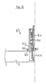
- FIG. 2 schematically shows a second embodiment of the safety device 9.
- the same reference numerals as in Figure 1 are used for the same components.
- the embodiment shown in Figure 2 differs only in that the outer clamping element 9.2 in a region 9.10 has a groove recess, which is preferably wedge-shaped.
- the inner clamping element 9.1 has at its periphery a recess 9.11 in which a clamping element 9.13 is pivotally mounted on a ring element 9.12.
- the trigger pin 11.6 has at its periphery an annular groove 11.7, the zuggrass forms an edge 11.8.
- the clamping wedge 9.13 abuts the edge 11.8 of the annular groove 11.7.
- the clamping wedge 9.10 turns from the locking position in the annular groove 11.7 of the pin 11.6 into the wedge-shaped groove recess 9.10 and releases the user-side linen part 11.4.
- the trigger pin 11.6 can be inserted into the inner clamping element 9.1, without the outer clamping element must be operated 9.2.
- the trigger pin 11.6 pushes the insertion of the clamping wedge 9.10 in a rotational movement upwards and laterally against a spring tongue 9.14 in the groove recess 9.10 and thus releases the opening of the inner clamping element 9.1.
- the trigger pin 9.6 inserted over the top of the clamping wedge 9.10 in the opening of the inner clamping element 9.1 presses the spring tongue 9.14 the clamping wedge 9.13 back and locks the trigger pin 11.6 in the position shown in Figure 1.
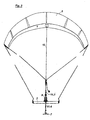
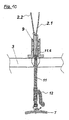
- FIG. 3 schematically shows the entire arrangement of the sports device 1 between a person (trapezoidal belt) 7 and the safety device 9.
- FIG. 5 schematically shows a development of the line 11.4 between the user 7 and the safety device 9.
- the handle 9 with its passage opening 3.1 and guided therein user-side linen part 11.4 and the safety line 13 offers the opportunity to be able to unravel it after rotation jumps or similar maneuvers freely.
- the leash 11 in the present embodiment is a so-called depower line, which in the prior art has a circular cross-section.
- the cross section may be polygonal or oval. Due to the formation of at least the Depowerleinenteils 11.4 with a non-uniform radius and in particular by the formation of the cross section in the form of a triangle, the Depowerleine 11 at a turn of the handlebar synchronously rotate with, since a rotational relative motion is hindered by positive engagement.
- a depower line 11 or such a depower part 11. 4 having a cross section which has different radii can be combined with the embodiments in FIG. 1 and FIG. 2.
- FIGS. 6 to 12 Further embodiments of the present invention and schematic illustrations are shown in FIGS. 6 to 12.
- FIG. 6 schematically shows a further embodiment of the safety device 9.
- the lower part is 9.7 of the inner clamping element 9.1 formed as a pin.
- the connection to the lower part of the tug 11.4 as "Übersch 11.6" is formed.
- a movement of the handle 3 upwards, in the direction of the tension element 5, then leads as in the embodiment in Figure 1 to the fact that the handle 3 overcomes the effect proximity to the safety device 9 and to the surface 9.4 of the flange abuts 9.3 and the outer clamping element 9.2 against the biasing force of the spring 9.5 moves upwards.
- the spring stop 9.6 of the inner clamping element 9.1 is formed as a threaded sleeve which is rotated to a thread in the upper circumference of the inner clamping element 9.1 and thus allows an individual default of the spring used 9.5.
- FIG. 7 shows a further developed embodiment of the safety device 9 according to the first embodiment in FIG.
- the release sleeve 9.2 is provided in this embodiment with an expandable diameter constriction 9.14 at the top. Upon displacement of the release sleeve 9.2 on the spring stop 9.6 of the inner sleeve 9.1 upwards away both elements are locked against the bias of the spring 9.5 by engaging the diameter constriction 9.14 each other.
- the required for spreading the lower part of the inner sleeve 9.1 9.15 is created with a hole in the lower part of the outer sleeve 9.2.
- the tripping pin 11.6 is polygonal outside (not round) executed to prevent relative rotations to the inner sleeve 9.1.
- the expandable inner sleeve lower part 9.7 is divided several times according to the shape of the tripping pin 11.6. The corners of the tripping pin 11.6 can engage in the interstices of the multiply divided inner sleeve lower part 9.7.
- connection of the pulling line upper part takes place by insertion and knotting through hole 9.10 in the shaft on the upper part of the inner sleeve 9.1.
- the safety line 13 is guided through the bore 9.11 in the shaft at the top of the inner sleeve 9.1 and connected to the user-side part of the pull line in the recess at the top of the tripping pin 11.6.
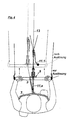
- Figure 8 shows a schematic plan view of a user who uses the sports device according to the invention and attacks with his hands on the handle, the solid lines show an active operating situation and the dashed lines show a deactive situation and motion arrows schematically represent the deactivation process.
- the functional diagram takes into account a connection with the handlebar 3 with a prior art collar or shackle release system 20 through the lines 18.
- the triggering mechanism 20 will be activated by the line 18 transmitted tensile force automatically actuated.
- the security line 13, which is centrally moved by the depower line 11, remains connected to the user 7.
- the handlebar 3 and the associated control lines 4 slip along the safety line 13 upwards.
- the stunt kite 5 falls down without pressure.
- Fig. 9 shows schematically a steering kite system which can be transmitted in the variant shown on all other described embodiments.
- the Consistor 12 in contrast to the systems known from the prior art, which use a Constant 12 for adjusting the length of the front lines 2.1 and 2.2 above the handlebar 3 on the stunt kite 5 facing side, the Consistierelement 12 in the embodiment shown here below the handlebar 3 used in the depower line 3. This creates the possibility, with the simultaneous use of the safety device 9, one of the front lines 2.1 as a continuous safety line with the releasable Depowerleinenunterteil 11 to connect.
- the use of an additional safety line 13 in this embodiment is not necessary. If the safety device 9 is triggered, then the handlebar 3 with the control lines 4 fastened thereto and the safety device 9 with the second front line 2.2 fastened to its upper part slide on the front line 2.1 running in the direction of the safety line of the steering kite 5. The only used by the continuous leash used as a continuous line 2.1 2.1 with the user 7 Steering kite 5 then falls down without pressure.
- Figure 10 shows a detailed diagram of the embodiment of Figure 9 with the connection of the front line 2.2 to the upper part of the inner clamping element 9.1 of the safety device 9 and the front line 2.1 as a continuous safety line with connection to the tripping pin 9.7 of the depower line 11 and the integration of the length adjustment 12 of the depower line below the handlebar 3.
- FIG. 11 schematically shows a further, further developed embodiment of the safety device 9.
- an elastomeric spring 9.5 is used in this embodiment, which can be adapted in various Shore hardnesses to individual needs of the release force.
- the replaceable elastomer spring 9.5 is stretched between release sleeve 9.2 and inner sleeve 9.1.
- Release sleeve 9.2 and inner sleeve 9.1 are assembled by means of an outer diameter extension at the lower end of the inner sleeve 9.1 9.7.
- the expandable lower part 9.7 of the inner sleeve 9.1 is compressed with disassembled trigger pin 11.6.
- the spring 9.5 and the outer sleeve 9.2 are pushed over the compressed inner sleeve lower part 9.7.
- a front line leads a short connecting line through a hole 9.11 in the upper lid he inner sleeve 9.1 and is secured with a knot against slipping.
- the other front line is called a continuous safety line through the second Bore in the upper cover of the inner sleeve 9.1 out and tied at the end of Depowerleinenunterteils 11 in the recess of the tripping pin 11.8.
- the recess for receiving the expandable inner sleeve lower part in the lower part of the outer sleeve is, as already described with reference to FIG 7, executed.
- the polygonal, ovale placed. not round shape of the tripping pin 11.6 with adapted form of the expandable lower part 9.7 of the inner sleeve 9.1 is carried out according to the descriptions with reference to FIG.
- FIG. 12 shows a further embodiment of the safety device 9, which is similar to the described embodiment according to FIG.
- the elastomeric spring used is 9.5 bonded to the bottom and top with centrally pierced discs 9.16.
- the spring element consisting of elastomer spring 9.5 and glued discs 9.16, screwed through the upper cover of the inner sleeve 9.1 with the inner sleeve 9.1.
- the second disc 9.16 on the lower part of the elastomeric spring 9.5 is screwed to the release sleeve 9.2.
- the embodiment shown here takes into account the use of an additional safety line 13, which is guided through the hole 9.11 in the lid at the top of the inner sleeve 9.1 and connected to the end of Depowerleinenunterteils 11 in the recess of the tripping pin 11.6.
- the upper part of the tug, to which the length adjuster 12 adjoins on the side facing the steer kite 5, is connected to a stirrup which is fastened to the upper side of the cover of the inner sleeve 9.1.
Abstract
Description
Die vorliegende Erfindung betrifft ein Sportgerät mit einem Haltegriff zum Festhalten und Steuern des Sportgerätes und mit einer Zugeinrichtung, die mit dem Haltegriff wirkverbunden ist und in einem aktiven Zustand eine Zugkraft auf den Haltegriff und ein angekoppeltes Objekt ausübt.The present invention relates to a sports device with a handle for holding and controlling the sports equipment and with a pulling device, which is operatively connected to the handle and exerts a pulling force on the handle and a coupled object in an active state.
Ein solches Sportgerät ist aus dem Stand der Technik z.B. als Lenkdrachen, Fallschirm, Paraglider, Flugdrachen oder auch als Sportboot, das Wasserski zieht. Es gibt viele Sportgeräte, die eine oder mehrere Personen mittels einer Zugeinrichtung ziehen. Alle diese Sportgeräte sollen unter den Oberbegriff der Ansprüche 1 und 24 fallen, sofern sie die darin genannten Merkmale aufweisen. Ein solches Sportgerät ist durch DE-U-20 209 515 bekannt.Such a sports equipment is known in the art e.g. as a stunt kite, parachute, paraglider, kite or even as a pleasure craft that waterskiing. There are many sports equipment that pull one or more people by means of a traction device. All these sports equipment should fall under the preamble of claims 1 and 24, provided that they have the features mentioned therein. Such a sports equipment is known from DE-U-20 209 515.
Die vorliegende Erfindung betrifft aber insbesondere solche Sportgeräte, bei denen die Zugeinrichtung ein Lenkdrachen ist. Sogenannte Lenkdrachenkites werden als Antrieb von Kite(Surf)-Boards, Snowkiteboards, Skiern, Buggies und anderen Fahrzeugen zu Sportzwecken verwendet. Der Kite ist dabei mit mehreren Leinen ausgestattet, die die Steuerung der Flugbewegungsrichtung und -geschwindigkeit sowie der Regulierung des Anstellwinkels, d.h., des Strömungswinkels, dienen. Die Steuerleinen sind dabei direkt mit einem Haltegriff bzw. einer Lenkstange oder Bar verbunden. Die Leinen zur Regulierung des Anstellwinkels werden noch oberhalb der Bar zu einer Zugleine bzw. Depowerleine zusammengefaßt. Diese Depowerleine wird durch eine Öffnung in der Barmitte oder durch eine mittig außen an der Bar befestigte Hülse geführt und an der Aufnahme, d.h., einem Haken, einer Öse, einem Schäkel o. dgl., eines um den Körper eines Benutzers gebundenen Trapezgurtes befestigt.However, the present invention relates in particular to those sports equipment in which the towing device is a stunt kite. So-called kite kites are used to power kite (surf) boards, snowkiteboards, skis, buggies and other sports vehicles. The kite is equipped with several lines which serve to control the direction of air movement and speed as well as the regulation of the angle of attack, i.e. the angle of flow. The steering lines are directly connected to a handle or a handlebar or bar. The lines for regulating the angle of attack are summarized above the bar to a tug or depower line. This depower line is passed through an opening in the center of the bar, or through a sleeve fixed centrally on the outside of the bar, and attached to the receptacle, i.e., a hook, eyelet, shackle, or the like, of a trapezoidal belt tied around a user's body.
Zusätzlich verbindet den Benutzer bei den bekannten Systemen eine Sicherheitsleine mit einer der Flugleinen, z.B. an einem Trapezhaken, einem Schäkel oder einem Handgelenk, oder mit den Bremsleinen, wie bei einem Softkite. Löst sich der Benutzer von der Bar und der Depowerleine, bleibt er mit dem nun zugkraftlosen Kite verbundenIn addition, in the known systems the user connects a safety line to one of the flying lines, e.g. on a harness hook, a shackle or a wrist, or with the brake lines, as in a soft kite. If the user breaks away from the bar and the depower line, he remains connected to the kite which is now without power
Der Lenkdrachen erzeugt durch Windströmung nach dem Tragflügelprinzip Auftriebskräfte, die als Zugkräfte über die Leinen zur Bar und zum Benutzer übertragen werden. Die auftriebsabhängigen Zugkräfte können durch relative Längenänderungen der Depower-und Heckleinen reguliert werden.The stunt kite generates buoyancy forces due to wind flow according to the wing principle, which are transmitted as pulling forces over the lines to the bar and to the user. The Buoyancy-related traction forces can be regulated by relative length changes of the depower and stern lines.
Schiebt der Benutzer die Bar über die mit dem Trapezgurt verbundene Depowerleine vom Körper weg, so werden die Steuerleinen entlastet, durch Kippen bzw. Entwölben des Kite-Profils wird der Auftrieb verringert, die Zugkräfte werden reduziert. Ein zusätzlicher dynamischer Auftrieb wird erzeugt, wenn der Kite durch einseitigen Leinenzug links oder rechts in eine Eigenbewegung, d.h., einen Flug auf einer Kreisbahn mit einem Radius in Leinenlänge, versetzt wird. Mit zunehmender Fluggeschwindigkeit des Drachens erhöht sich der dynamische Auftrieb nach dem Bernoullischen Prinzip. Die auf den Benutzer wirkenden Kräfte nehmen zu. Beim Start der Fahrbewegung oder zur Erhöhung der Fahrgeschwindigkeit wird ein solcher Steuerimpuls absichtlich erzeugt.If the user pushes the bar away from the body via the depower line connected to the trapeze belt, the control lines are relieved, and tilting or deconstructing the kite profile reduces lift and reduces pulling forces. An additional dynamic buoyancy is created when the kite is put into a proper motion, i.e. a flight on a circular path with a line-length radius, by unilateral line pulling left or right. As the speed of the kite increases, dynamic lift increases according to the Bernoulli principle. The forces acting on the user increase. At the start of the driving movement or to increase the driving speed, such a control pulse is intentionally generated.
Bei böigen, plötzlich stark zunehmenden Winden, fehlerhaften (überzogenen) Steuerbewegungen oder Orientierungsverlusten bei Sprung- oder Trickmanövern etc. wird ein sprunghafter Zugkraftanstieg jedoch auch unbeabsichtigt und unkontrolliert ausgelöst. In einem sich aus einer solchen beschriebenen Situation entwickelnden Notfall wird der Kite Kräfte entwickeln, die ein Mehrfaches des Eigengewichts des Benutzers betragen können, wobei mehr als 200 kg möglich sind.In gusty, suddenly strong winds, erroneous (exaggerated) control movements or orientation losses in jumping or trick maneuvers etc., however, a sudden increase in traction is also triggered unintentionally and uncontrollably. In an emergency evolving from such a described situation, the kite will develop forces that can amount to several times the user's own weight, with more than 200 kg being possible.
Die Folge ist ein totaler Kontrollverlust. Der Benutzer wird in der Regel bei zusätzlicher Eigenrotation um die Körperlängsachse orientierungslos hinter dem Kite hergezogen. Dieser Zustand hält an, bis das Kite aus seiner Eigenbewegung möglicherweise abstürzt oder der Benutzer unter Zugkraft gegen Hindernisse geschleudert wird.The result is a total loss of control. As a rule, the user is pulled behind the body longitudinal axis with no additional self-rotation behind the kite. This condition persists until the kite may crash out of its own motion or the user may be thrown against obstacles with traction.
Zur Gefahrenabwehr für den Benutzer und für Dritte ergibt sich damit eine Notwendigkeit, die Zugkraftverbindung zwischen dem Benutzer und dem Kite in der Weise ohne einschränkende Bedingungen entkoppeln zu können, daß der Kite möglichst schnell zugkraftlos wird. Bei einem bloßen Lösen der Hände von der Bar bleiben die über die Depowerleine zum Trapezgurt des Benutzers übertragenen Zugkräfte erhalten. Die Gefahrensituation wird dadurch nicht entspannt.To avoid danger to the user and third parties, this results in a need to be able to decouple the tensile force connection between the user and the kite in such a way without restrictive conditions that the kite is as fast as possible without power. By simply releasing the hands from the bar, the traction forces transmitted via the depower line to the trapeze belt of the user are maintained. The danger situation is not relaxed thereby.
Bislang sind zum Lösen der kritischen Verbindung zwischen Benutzer und Depowerleine nur Klapphaken, sogenannte Panikschäkel oder Panikhaken, Klettbandverbindungen und leashes bekannt, die in der Depowerleine unterhalb der Bar, also auf der dem Benutzer zugewandten Seite, eingesetzt oder direkt mit dem Trapezhaken und/oder der Trapezplatte verbunden werden.So far, to solve the critical connection between the user and Depowerleine only folding hooks, so-called panic shackles or panic hooks, Velcro connections and leashes known, which are used in the depower line below the bar, ie on the side facing the user, or connected directly to the harness hook and / or the trapezoidal plate.
Alle bekannten Systeme ermöglichen die Entkopplung der Zugkraftübertragung erst unter den folgenden, sicherheitsrelevant einschränkenden Bedingungen:
- 1. Der Benutzer muß mindestens eine Hand von dem Handgriff bzw. der Lenkstange lösen, um den Auslöser erreichen zu können.
- 2. Der Benutzer muß nach dem Loslassen der Lenkstange in einer zielgerichteten und damit kontrollierten Handlung nach dem Bedienteil greifen und dieses blind finden, um den Mechanismus auslösen zu können.
- 1. The user must detach at least one hand from the handle or the handlebar to reach the trigger can.
- 2. The user must grab after releasing the handlebar in a targeted and thus controlled action for the control panel and find this blind to trigger the mechanism can.
Die bekannten Systeme lassen das erhebliche Sicherheitsproblem damit weitgehend ungelöst, da gerade in einer Notsituation, die in der hier zu bewertenden Weise von einem systemimmanenten Orientierungs- und Kontrollverlust begleitet wird, die zur Kraftentkopplung erforderlichen zielgerichteten und kontrollierten Handlungen nicht mehr ausführbar sind. Dies gilt um so mehr, da der Benutzer das einzig zur Verfügung stehende Kontrollinstrument, nämlich die Lenkstange, loslassen muß, bevor der zielgerichtete Griff nach der Auslösevorrichtung überhaupt erst folgen kann.The known systems thus leave the considerable security problem largely unresolved, since it is precisely in an emergency situation, which is accompanied by a system-immanent orientation and control loss in the manner to be evaluated here, that the targeted and controlled actions required for power decoupling can no longer be carried out. This is even more so since the user must release the only control instrument available, namely the handlebar, before the targeted grip on the triggering device can follow at all.
Die Aufgabe der Erfindung ist daher, ein Sportgerät der eingangs genannten Art dahin gehend weiter zu bilden, daß eine durch einen Kontrollverlust herbei geführte Gefahrensituation zuverlässig und schnell beendet werden kann.The object of the invention is therefore to continue to form a sports equipment of the type mentioned in that a caused by a loss of control induced dangerous situation can be completed reliably and quickly.
Die Aufgabe wird erfindungsgemäß dadurch gelöst, daß in Wirknähe des Handgriffs eine Sicherheitseinrichtung angeordnet ist, welche die Zugeinrichtung beim Erreichen eines Schwellenwertes der Zugkraft deaktiviert.The object is achieved in that a safety device is arranged in the vicinity of the handle, which deactivates the traction device upon reaching a threshold value of the tensile force.
Die Aufgabe wird auch dadurch gelöst, daß die Depowerleine einen Querschnitt mit unterschiedlichen Radien aufweist und durch eine Sicherheitseinrichtung durchgeführt ist, die in Wirknähe des Haltegriff angeordnet ist und die Zugeinrichtung beim Erreichen eines Schwellenwertes der Zugkraft deaktiviert.The object is also achieved in that the depower line has a cross section with different radii and is performed by a safety device which is arranged in the vicinity of the handle and the traction device deactivated upon reaching a threshold value of the tensile force.
Mit der erfindungsgemäßen Vorrichtung nach Anspruch 1 ist es möglich, daß eine Kraftentkopplung direkt über den Haltegriff betätigt werden kann, ohne daß der Benutzer seine Hände von dem Haltegriff lösen muß.With the device according to the invention according to claim 1, it is possible that a power decoupling can be operated directly on the handle without the user must solve his hands from the handle.
Ein weiterer Vorteil der vorliegenden Erfindung gemäß Anspruch 2 besteht darin, daß die Deaktivierung der Zugeinrichtung in Abhängigkeit von einer Bewegung des Haltegriffs in einer Wirkrichtung der Zugkraft erfolgt. Der Benutzer muß zur Deaktivierung lediglich den Haltegriff in Wirkrichtung der Zugkraft der Zugeinrichtung bewegen, um den Auslösemechanismus zu betätigen und die Zugeinrichtung zu deaktivieren.Another advantage of the present invention according to claim 2 is that the deactivation of the pulling device in response to a movement of the handle in a direction of action of the tensile force takes place. The user must move to deactivate only the handle in the direction of action of the pulling force of the pulling device to operate the trigger mechanism and disable the pulling device.
Ein weiterer Vorteil gemäß Anspruch 3 besteht darin, daß die Deaktivierung der Zugeinrichtung auch automatisch erfolgen kann, indem die Sicherheitseinrichtung bei Erreichen eines vorbestimmten Grenzwertes auslöst und die Zugeinrichtung deaktiviert. Dies kann alternativ oder zusätzlich zu der bewegungsabhängigen Deaktivierung vorgesehen sein, um z.B. ein sichereres Training zu ermöglichen.Another advantage according to
Ausführungsform der vorliegenden Erfindung werden im folgenden anhand der Zeichnungen näher beschrieben. Es zeigen:
- Fig. 1 eine schematische Teilansicht im Querschnitt eines Haltegriffs im Bereich des Durchgangs einer Leine bzw. Depowerleine und mit einer erfindungsgemäßen Sicherheitseinrichtung;
- Fig. 2 eine schematische Teilansicht im Querschnitt einer zweiten Ausführungsform der vorliegenden Erfindung;
- Fig. 3 eine schematische Ansicht eines Sportgerätes gemäß vorliegender Erfindung, an welchem der Haltegriff aus Fig. 1 oder Fig. 2 angebracht ist;
- Fig. 4 eine schematische Draufsicht auf einen Benutzer, der das erfindungsgemäße Sportgerät benutzt und mit seinen Händen an den Haltegriff angreift, wobei die durchgezogenen Linien eine aktive Betriebssituation zeigen und gestrichelte Linien eines deaktive Situation zeigen und Bewegungspfeile den Deaktivierungsvorgang schematisch darstellen;
- Fig. 5 eine schematische Darstellung einer erfindungsgemäßen Depowerleine;
- Fig.6 eine schematische Darstellung einer zweiten Ausführungsform der Sicherheitseinrichtung;
- Fig. 7 eine schematische Darstellung einer dritten Ausführungsform der Sicherheitseinrichtung;
- Fig. 8 eine schematische Draufsicht auf das erfindungsgemäße Sportgerät in einer dritten Ausführungsform;
- Fig. 9 eine schematische Darstellung eines erfindungsgemäßen Lenkdrachensystems;
- Fig. 10 eine Detaildarstellung der Ausführungsform nach
Figur 9; - Fig. 11 eine schematische Darstellung einer vierten Ausführungsform der Sicherheitseinrichtung; und
- Fig. 12 eine schematische Darstellung einer fünften Ausführungsform der Sicherheitseinrichtung.
- Figure 1 is a schematic partial view in cross section of a handle in the region of the passage of a leash or depower line and with a safety device according to the invention.
- Fig. 2 is a schematic partial cross-sectional view of a second embodiment of the present invention;
- Fig. 3 is a schematic view of a sports equipment according to the present invention to which the handle of Fig. 1 or Fig. 2 is attached;
- 4 is a schematic plan view of a user using the sports equipment of the present invention and engaging his hands on the handle, the solid lines showing an active operating situation and dashed lines showing an inactive situation and movement arrows schematically illustrating the deactivation process;
- 5 shows a schematic representation of a depower line according to the invention;
- 6 shows a schematic representation of a second embodiment of the safety device;
- Fig. 7 is a schematic representation of a third embodiment of the safety device;
- 8 is a schematic plan view of the sports equipment according to the invention in a third embodiment;
- 9 shows a schematic representation of a steering kite system according to the invention;
- Fig. 10 is a detail view of the embodiment of Figure 9;
- 11 is a schematic representation of a fourth embodiment of the safety device; and
- Fig. 12 is a schematic representation of a fifth embodiment of the safety device.
In Fig. 1 ist schematisch ein Teil eines Sportgeräts 1 dargestellt. Ein Haltegriff 3 ist in der dargestellten Ausführungsform als Lenkstange ausgebildet und weist in seiner Mitte eine Durchgangsöfmung 3.1 auf. Die Seite des Haltegriffs 3, die in Fig. 1 oberhalb des Haltegriffs 3 liegt, ist die sogenannten Zugseite, das heißt, die Seite, die einer auf den Haltegriff 3 wirkenden Zugeinrichtung 5 (Figur 3) zugewandt ist. Die Seite, welche unterhalb des Haltegriffs 3 liegt, ist die Seite, die einem Trapezgurt, Objekt oder Benutzer 7 (Figur 3) zugewandt ist.In Fig. 1, a part of a sports equipment 1 is shown schematically. A
An dem Haltegriff 3 ist eine Sicherheitseinrichtung 9 angeordnet. Wenn die Zugeinrichtung 5 in einem aktiven Zustand, das heißt, im Betrieb des Sportgerätes 1 eine Zugkraft auf den Haltegriff 3 ausübt und ein Schwellenwert erreicht wird, deaktiviert die Sicherheitseinrichtung 9 die Zugeinrichtung 5. Die Deaktivierung erfolgt in der vorliegenden Ausführungsform durch eine Kraftentkopplung der auf den Haltegriff 3 und den Benutzer 7 wirkenden Zugkraft. Die Deaktivierung kann wahlfrei durch den Benutzer während des Betriebes ausgelöst werden, das heißt, der Schwellenwert kann für jeden Benutzer 7 ein subjektiv wahrgenommener Wert sein. Die manuelle Auslösung der Deaktivierung der Zugeinrichtung 5 erfolgt in Abhängigkeit von einer Bewegung des Haltegriffs 3 in einer Wirkrichtung der Zugkraft (Figur 4). Alternativ oder zusätzlich kann die Deaktivierung der Zugeinrichtung 5 auch in Abhängigkeit vom Erreichen eines vorbestimmten Grenzwertes der Zugkraft automatisch ausgelöst werden. Es ist möglich, den Grenzwert einer Zugkraft vor einer Betriebsaufnahme einzustellen. Dies kann z.B. in Abhängigkeit von dem Leistungsvermögen des Benutzers 7 erfolgen. Ein Kriterium für das Leistungsvermögen kann der Ausbildungsstand an dem Sportgerät aber auch das Alter des Benutzers und sein Gewicht sein.On the
Die Sicherheitseinrichtung 9 ist in der vorliegenden Ausführungsform an einer Leine 11 angeordnet, die durch die Öffnung 3.1 in dem Haltegriff 3 hindurch geführt ist. Die Sicherheitseinrichtung 9 ist an der Leine 11 in Wirkrichtung der Zugkraft in Wirknähe hinter dem Haltegriff 3 angeordnet, das heißt, auf der Zugseite in Figur 1. Mit "Wirknähe" ist hier eine solche Nähe gemeint, die in dem Fall, daß das Objekt 7 ein Benutzer ist, maximal einer Armlänge des Benutzers entspricht. Die Entfernung ist aber einstellbar. Die Wirknähe soll eine solche Nähe sein, daß der Haltegriff 3 mit einer Bewegung noch auf die Sicherheitseinrichtung 9 einwirken kann.The
Die Sicherheitseinrichtung 9 weist in inneres Spannelement 9.1 und eine äußeres Spannelement 9.2 auf, die in einer Wirkrichtung der Zugkraft gegeneinander vorgespannt sind und gegen die Vorspannung relativ zueinander verschiebbar angeordnet sind. Das äußere Spannelement 9.2 weist haltegriffseitig einen Flansch 9.3 auf, der das äußere Spannelement 9.2 kranzförmig umschließt und haltegriffseitig eine Anstoßfläche für den Haltegriff 3 bildet. Der Flansch 9.3 geht zugseitig in einen Hülsenteil 9.4 über, der mit einer Innenwand gleitfähig an einer Außenwand des inneren Spannelement 9.1 anliegt. Das Hülsenteil 9.4 weist an seinem zugseitigen Ende eine geringere Wandstärke auf als an seinem flanschseitigen Ende, wobei die Innenwand des Hülsenteils 9.4 am zugseitigen Ende abgestuft ist, so daß dort zwischen dem Hülsenteil 9.4 und dem inneren Spannelement 9.1 ein Aufnahmeraum für ein Federelement 9.5 ausgebildet ist. Das Federelement 9.5 ist im vorliegenden Fall eine Schraubenfeder mit einer einheitlichen Federkonstante. Es ist denkbar, daß das Federelement 9.5 eine variierende Federkonstante hat, so daß die Federkraft über einen Einstellmechanismus (nicht dargestellt) einstellbar ist. Das innere Spannelement 9.1 weist an seinem Umfang einen Ansatz 9.6 auf, der den zwischen dem Hülsenteil 9.4 und dem Spannelement 9.1 gebildeten Aufnahmeraum zugseitig abschließt. Das Federelement 9.5 stützt sich an dem Ansatz 9.6 und an der Stufe im Hülsenteil 9.4 ab, wodurch das innere Spannelement 9.1 und das äußere Spannelement 9.2 gegeneinander vorgespannt sind.The
Das innere Spannelement 9.1 ist hülsenförmig ausgebildet und weist an seinem haltegriffseitigen Ende eine erste innen liegende Ringnut 9.7 auf. Das innere Spannelement 9.1 weist zudem an seinem zugseitigen Ende eine zweite innen liegende Ringnut 9.8 auf. Die Leine 11 weist ein erstes zugseitiges Leinenteil 11.1 auf, das an einem freien Ende 11.2 mit einem Zapfen 11.3 verbunden ist, der formschlüssig in der Ringnut 9.8 sitzt. Ein Klemmelement 9.9 ist am zugseitigen Ende des inneren Spannelements 9.1 angebracht, und erzeugt eine Klemmspannung, derart, daß der Zapfen 11.3 fest in der Ringnut 9.8 eingespannt ist. Das Klemmelement 11.3 kann z.B. eine Klemmmutter sein. Die Leine 11 umfaßt auch ein zweites benutzerseitiges Leinenteil 11.4, das an seinem freien Ende 11.5 einen Auslösezapfen 11.6 aufweist, der in der vorliegenden Ausführungsform identisch mit dem Zapfen 11.3 ist. Der Auslösezapfen 11.6 sitzt formschlüssig in der ersten Ringnut 9.7 und ist dort durch das äußere Spannelement 9.2 fest eingespannt. Die Leine 11 bzw. die Leinenteile 11.1 und 11.4 sowie die Zapfen 11.3 und 11.6 sind hohl bzw. mit einem zentralen Durchgang ausgebildet, in welchem eine Sicherheitsleine 13 verläuft.The inner clamping element 9.1 is sleeve-shaped and has at its handle-side end a first inner annular groove 9.7. The inner clamping element 9.1 also has at its zugseitigen end a second inner annular groove 9.8. The
Eine Bewegung des Haltegriffs 3 in Figur 1 nach oben, das heißt, in Richtung des Zugelements 5 bzw. in Wirkrichtung einer Zugkraft führt dazu, daß der Haltegriff 3 die Wirknähe überwindet und an die Fläche 9.4 des Flansches 9.3 anstößt und das äußere Spannelement 9.2 in Figur 1 gegen die Vorspannkraft der Feder 9.5 nach oben schiebt. Dadurch wird die Klemmspannung auf die erste Ringnut 9.7 und den darin sitzenden Auslösezapfen 11.6 weg genommen, so daß das benutzerseitige Leinenteil 11.4 der Leine 11 aus der ersten Ringnut 9.7 rutscht und sich aus der kraftschlüssigen Verbindung mit dem zugseitigen Leinenteil 11.1 löst. Dadurch ist dann die Zugkraft entkoppelt.A movement of the
Alternativ wäre auch vorstellbar, daß die Leine 11 nicht geteilt ist und in dem innere Spannelement 9.1 nur eine Ringnut 9.8 oder 9.7 ausgebildet ist, in der ein an der Leine ausgebildeter Vorsprung fest sitzt. Die weitere Auslösemechanik kann identisch zu derjenigen bleiben, die vorstehend beschrieben wurde. Die Leine 11 müßte in diesem Fall benutzerseitig von der Ringnut einen Leinenvorrat aufweisen, der im Falle einer Auslösung zu einer vorübergehenden Kraftentkopplung führt. Eine solche Ausführungsform kann dort eingesetzt werden, wo eine solche vorübergehende Kraftentkopplung ausreicht, um eine sichere Kontrolle über das Sportgerät 1 wieder zu gewinnen.Alternatively, it would also be conceivable that the
In Figur 2 ist schematisch eine zweite Ausführungsform der Sicherheitseinrichtung 9 dargestellt. In Figur 2 werden für die gleichen Bauteile auch die gleichen Bezugszeichen wie in Figur 1 verwendet. Die in Figur 2 dargestellte Ausführungsform unterscheidet sich lediglich darin, daß das äußere Spannelement 9.2 in einem Bereich 9.10 eine Nutaussparung aufweist, die vorzugsweise keilförmig ausgebildet ist. Das innere Spannelement 9.1 weist an seinem Umfang eine Aussparung 9.11 auf, in der auf einem Ringelement 9.12 ein Klemmkeil 9.13 schwenkbar angeordnet ist. Der Auslösezapfen 11.6 weist an seinem Umfang eine Ringnut 11.7 auf, die zugseitig eine Kante 11.8 bildet. Im verriegelten Zustand stößt der Klemmkeil 9.13 an der Kante 11.8 der Ringnut 11.7 an. Wenn der Haltegriff 3 in Figur 2 nach oben bewegt wird, dreht sich der Klemmkeil 9.10 aus der Arretierungsposition in der Ringnut 11.7 des Zapfens 11.6 in die keilförmige Nutaussparung 9.10 und gibt das benutzerseitige Leinenteil 11.4 frei.FIG. 2 schematically shows a second embodiment of the
Die Funktion des in Figur 2 beschriebenen Ausführungsbeispiels zur Anwendung der Erfindung unterscheidet sich von dem Ausführungsbeispiel in Figur 1 in der Art des Arretierungsmechanismusses. Wird die Verbindung von Ober- und Unterteil der Leine 11.4 beabsichtigt, so ist in dem Ausführungsbeispiel nach Figur 1 das äußere Spannelement 9.2 zunächst in Wirkrichtung der Zugkraft nach oben zu schieben, bevor der Auslösezapfen 11.6 gegen den Spreizungswiderstand des haltegriffseitigen Endes des inneren Spannelements 9.1 in dessen Ringnut 9.7 eingeschoben werden kann. Das äußere Spannelement 9.2 muß also gegen die Kraftwirkung der Feder 9.5 relativ zum inneren Spannelement 9.1 verschoben werden.The function of the embodiment described in Figure 2 for the application of the invention differs from the embodiment in Figure 1 in the type of Arretierungsmechanismusses. If the connection of the upper and lower part of the line 11.4 is intended, then in the embodiment of Figure 1, the outer clamping element 9.2 initially push in the effective direction of the tensile force up before the tripping pin 11.6 against the spreading resistance of the handle-side end of the inner clamping element 9.1 in its annular groove 9.7 can be inserted. The outer clamping element 9.2 must therefore be moved against the force of the spring 9.5 relative to the inner clamping element 9.1.
Wird die Verbindung von Ober- und Unterteil der Leine 11 in dem Ausführungsbeispiel aus Figur 2 beabsichtigt, so kann der Auslösezapfen 11.6 in das innere Spannelement 9.1 eingeschoben werden, ohne daß das äußere Spannelement 9.2 betätigt werden muß. Der Auslösezapfen 11.6 drückt beim Einschub den Klemmkeil 9.10 in einer Rotationsbewegung nach oben und seitlich gegen eine Federzunge 9.14 in der Nutaussparung 9.10 und gibt damit die Öffnung des inneren Spannelements 9.1 frei. Ist der Auslösezapfen 9.6 über die Spitze des Klemmkeils 9.10 hinweg in die Öffnung des inneren Spannelements 9.1 eingeschoben, drückt die Federzunge 9.14 den Klemmkeil 9.13 zurück und arretiert den Auslösezapfen 11.6 in der in Figur 1 abgebildeten Position.If the connection of upper and lower part of the
In Figur 3 ist schematisch die gesamte Anordnung des Sportgerätes 1 zwischen einer Person (Trapezgurt) 7 und mit der Sicherheitseinrichtung 9 dargestellt.FIG. 3 schematically shows the entire arrangement of the sports device 1 between a person (trapezoidal belt) 7 and the
In Figur 4 ist schematisch die manuelle Auslösung der Sicherheitseinrichtung 9 dargestellt. Der Benutzer 7 schiebt mit seinen Händen den Haltegriff 3 in Figur 1 nach oben (Pfeilrichtung) und löst das benutzerseitige Teil der Leine 11.4 aus der Sicherheitseinrichtung 9..In Figure 4, the manual release of the
In Figur 5 ist schematisch eine Weiterbildung der Leine 11.4 zwischen dem Benutzer 7 und der Sicherheitseinrichtung 9 dargestellt. Der Handgriff 9 mit seiner Durchgangsöffnung 3.1 und dem darin geführten benutzerseitigen Leinenteil 11.4 und der Sicherheitsleine 13 bietet die Möglichkeit, diese nach Rotationssprüngen oder ähnlichen Manövern frei entdrehen zu können. Die Leine 11 ist in der vorliegenden Ausführungsform eine sogenannte Depowerleine, die im Stand der Technik einen kreisförmigen Querschnitt aufweist. Bei Verdrehungen des benutzerseitigen Depowerleinenteils 11.4 und der in dem kreisförmigen Hohlraum des Depowerleinenteils 11.4 geführten Sicherheitsleine 13 und anschließenden Entdrehungen der Lenkstange 3 ist ohne die zusätzliche Verwendung von Lagerungen (Schäkel o.ä.) nicht gewährleistet, daß sich auch die Depowerleine 11.4 wieder entdreht, weil sie an den Innenwänden der Führung a in der Lenkstange 3 entlang rutscht. Es ist daher in Figur 5 eine Weiterbildung des Depowerleinenteils 11.4 dargestellt, mit der dieser gezwungen werden kann, sich bei einer Drehung der Lenkstange 3 mit zu drehen.
Zu diesem Zweck ist das Depowerleinenteil 11.4 wenigstens benutzerseitig mit einem Querschnitt versehen, der unterschiedliche Radien aufweist. In Figur 5 ist der Querschnitt dreieckig dargestellt. In anderen Ausführungsformen kann der Querschnitt mehreckig oder auch oval sein. Durch die Ausbildung wenigstens des Depowerleinenteils 11.4 mit einem ungleichmäßigen Radius und insbesondere durch die Ausbildung des Querschnitts in Form eines Dreieckes, wird die Depowerleine 11 bei einer Entdrehung der Lenkstange synchron mit drehen, da eine rotatorische Relativbewegung durch Formschluß behindert wird. Eine solche Depowerleine 11 bzw. ein solches Depowerleinenteil 11.4 mit einem Querschnitt, der unterschiedliche Radien aufweist, kann mit den Ausführungsformen in Figur 1 und Figur 2 kombiniert werden.FIG. 5 schematically shows a development of the line 11.4 between the
For this purpose, the Depowerleinenteil 11.4 is provided at least user side with a cross section having different radii. In Figure 5, the cross section is triangular. In other embodiments, the cross section may be polygonal or oval. Due to the formation of at least the Depowerleinenteils 11.4 with a non-uniform radius and in particular by the formation of the cross section in the form of a triangle, the
Weitere Ausführungsformen der vorliegenden Erfindung und schematische Darstellungen werden mit den Figuren 6 bis 12 gezeigt.Further embodiments of the present invention and schematic illustrations are shown in FIGS. 6 to 12.
In Figur 6 ist schematisch eine weitere Ausführungsform der Sicherheitseinrichtung 9 dargestellt. Gegenüber der Ausführungsform, die in Figur 1 dargestellt ist, ist das Unterteil 9.7 des inneren Spannelementes 9.1 als Zapfen ausgebildet. Entsprechend ebenfalls umgekehrt zu der Ausführungsform nach Figur 1 ist der Anschluß an das Unterteil der Zugleine 11.4 als "Überwurf 11.6" ausgebildet. Eine Bewegung des Haltegriffes 3 nach oben, in Richtung des Zugelementes 5, führt dann wie bei der Ausführungsform in Figur 1 dazu, daß der Haltegriff 3 die Wirknähe zur Sicherheitseinrichtung 9 überwindet und an die Fläche 9.4 des Flansches 9.3 anstößt und das äußere Spannelement 9.2 gegen die Vorspannkraft der Feder 9.5 nach oben verschiebt. Dadurch wird die Klemmspannung, die auf die geschlitzte Ausführung des Überwurfes 11.6 zur Ringnut des Zapfens 9.7 übertragen wird, gelöst, so daß das benutzerseitige Leinenteil 11.4 der Leine 11 herausrutscht und sich aus der kraftschlüssigen Verbindung mit dem zugseitigen Leinenteil 11.1 löst. Die Zugkraft ist dann entkoppelt.FIG. 6 schematically shows a further embodiment of the
Ein weiterer Unterschied ergibt sich in der Ausführung des Federanschlages 9.6 des inneren Spannelementes 9.1. In der hier vorliegenden Ausführungsform ist der Federanschlag 9.6 als Gewindehülse ausgebildet, die auf ein Gewinde im oberen Umfang des inneren Spannelementes 9.1 gedreht wird und damit eine individuelle Voreinstellung der verwendeten Feder 9.5 zuläßt.Another difference arises in the embodiment of the spring stop 9.6 of the inner clamping element 9.1. In the present embodiment, the spring stop 9.6 is formed as a threaded sleeve which is rotated to a thread in the upper circumference of the inner clamping element 9.1 and thus allows an individual default of the spring used 9.5.
In Figur 7 wird eine weiterentwickelte Ausführungsform der Sicherheitseinrichtung 9 entsprechend der ersten Ausführungsform in Figur 1 gezeigt.FIG. 7 shows a further developed embodiment of the
Die Auslösehülse 9.2 wird in dieser Ausführungsform mit einer spreizbaren Durchmesserverengung 9.14 am oberen Ende versehen. Bei Verschiebung der Auslösehülse 9.2 über den Federanschlag 9.6 der Innenhülse 9.1 nach oben hin weg werden beide Elemente gegen die Vorspannung der Feder 9.5 durch Einrasten der Durchmesserverengung 9.14 miteinander verriegelt. Der zur Spreizung des Unterteiles der Innenhülse 9.1 erforderliche Raum 9.15 wird mit einer Bohrung im Unterteil der Außenhülse 9.2 geschaffen. Der Auslösezapfen 11.6 wird außen mehreckig (nicht rund) ausgeführt, um relative Rotationen zur Innenhülse 9.1 zu verhindern. Das spreizbare Innenhülsenunterteil 9.7 wird entsprechend der Form des Auslösezapfens 11.6 mehrfach geteilt. Die Ecken des Auslösezapfens 11.6 können in die Zwischenräume des mehrfach geteilten Innenhülsenunterteils 9.7 eingreifen.The release sleeve 9.2 is provided in this embodiment with an expandable diameter constriction 9.14 at the top. Upon displacement of the release sleeve 9.2 on the spring stop 9.6 of the inner sleeve 9.1 upwards away both elements are locked against the bias of the spring 9.5 by engaging the diameter constriction 9.14 each other. The required for spreading the lower part of the inner sleeve 9.1 9.15 is created with a hole in the lower part of the outer sleeve 9.2. The tripping pin 11.6 is polygonal outside (not round) executed to prevent relative rotations to the inner sleeve 9.1. The expandable inner sleeve lower part 9.7 is divided several times according to the shape of the tripping pin 11.6. The corners of the tripping pin 11.6 can engage in the interstices of the multiply divided inner sleeve lower part 9.7.
Der Anschluß des Zugleinenoberteils erfolgt durch Einführen und Verknoten durch Bohrung 9.10 im Schaft am Oberteil der Innenhülse 9.1. Die Sicherheitsleine 13 wird durch die Bohrung 9.11 im Schaft an der Oberseite der Innenhülse 9.1 geführt und mit dem benutzerseitigen Teil der Zugleine in der Aussparung an der Oberseite des Auslösezapfens 11.6 verbunden.The connection of the pulling line upper part takes place by insertion and knotting through hole 9.10 in the shaft on the upper part of the inner sleeve 9.1. The
Figur 8 zeigt eine schematische Draufsicht auf einen Benutzer, der das erfindungsgemäße Sportgerät benutzt und mit seinen Händen an den Haltegriff angreift, wobei die durchgezogenen Linien eine aktive Betriebssituation und die gestrichelten Linien eine deaktive Situation zeigen und Bewegungspfeile den Deaktivierungsvorgang schematisch darstellen. Das Funktionsschema berücksichtigt in der hier gezeigten Ausführungsform eine Verbindung mit der Lenkstange 3 mit einem nach dem Stand der Technik bekannten Manschetten- oder Schäkelauslösesystem 20 durch die Leinen 18. Läßt der Benutzer die Lenkstange 3 los, wird der Auslösemechanismus 20 durch den über die Leinen 18 übertragene Zugkraft automatisch betätigt. Die mittig durch die Depowerleine 11 gerührte Sicherheitsleine 13 bleibt mit dem Benutzer 7 verbunden. Die Lenkstange 3 und die damit verbundenen Steuerleinen 4 rutschen entlang der Sicherheitsleine 13 nach oben. Der Lenkdrachen 5 fällt drucklos herunter.Figure 8 shows a schematic plan view of a user who uses the sports device according to the invention and attacks with his hands on the handle, the solid lines show an active operating situation and the dashed lines show a deactive situation and motion arrows schematically represent the deactivation process. The functional diagram, in the embodiment shown here, takes into account a connection with the
Mit dem hier gezeigten Auslöseschema können nach dem Stand der Technik bereits bekannte Manschetten- oder Schäkelsysteme, die teilweise marktgängig sind, ebenfalls durch aktives Wegdrücken der Lenkstange 3 in Richtung des Lenkrachens 5 oder abhängig von der Einstellung durch bloßes Loslassen der Hände von der Lenkstange 3 zuverlässig entkoppelt werden.With the triggering scheme shown here can already known cuff or Schäkelsysteme that are partially marketable, also by actively pushing away the
Fig. 9 zeigt schematisch ein Lenkdrachensystem, das in der gezeigten Variante auf alle weiteren beschriebenen Ausführungsformen übertragen werden kann. Im Unterschied zu den nach dem Stand der Technik bekannten Systeme, die ein Längenjustierelement 12 zur Einstellung der Länge der Frontleinen 2.1 und 2.2 oberhalb der Lenkstange 3 auf der dem Lenkdrachen 5 zugewandten Seite verwenden, wird das Längenjustierelement 12 in der hier gezeigten Ausführung unterhalb der Lenkstange 3 in die Depowerleine 3 eingesetzt. Damit entsteht die Möglichkeit, bei gleichzeitiger Verwendung der Sicherheitseinrichtung 9 eine der Frontleinen 2.1 als durchlaufende Sicherheitsleine mit dem auslösbaren Depowerleinenunterteil 11 zu verbinden.Fig. 9 shows schematically a steering kite system which can be transmitted in the variant shown on all other described embodiments. In contrast to the systems known from the prior art, which use a
Im Gegensatz zu den bisher gezeigten Anordnungsschemata wird die Verwendung einer zusätzlichen Sicherheitsleine 13 in dieser Ausführungsform nicht notwendig. Wird die Sicherheitseinrichtung 9 ausgelöst, so rutscht die Lenkstange 3 mit den daran befestigten Steuerleinen 4 sowie die Sicherheitseinrichtung 9 mit der an deren Oberteil befestigten zweiten Frontleine 2.2 auf der als Sicherheitsleine durchlaufenden Frontleine 2.1 in Richtung des Lenkdrachens 5. Der nur noch durch die als durchlaufende Sicherheitsleine verwendete Frontleine 2.1 mit dem Benutzer 7 verbundene Lenkdrachen 5 fällt dann drucklos herunter.In contrast to the arrangement schemes shown so far, the use of an
Figur 10 zeigt ein Detailschema der Ausführungsform nach Figur 9 mit dem Anschluß der Frontleine 2.2 an das Oberteil des inneren Spannelementes 9.1 der Sicherheitseinrichtung 9 und der Frontleine 2.1 als durchlaufende Sicherheitsleine mit Anschluß an den Auslösezapfen 9.7 der Depowerleine 11 und die Einbindung des Längenjustierelementes 12 der Depowerleine unterhalb der Lenkstange 3.Figure 10 shows a detailed diagram of the embodiment of Figure 9 with the connection of the front line 2.2 to the upper part of the inner clamping element 9.1 of the
In Figur 11 ist schematisch eine weitere, weiterentwickelte Ausführungsform der Sicherheitseinrichtung 9 dargestellt. Anstelle der in den bisherigen Ausführungsvarianten verwendeten Schrauben 9.5 wird in dieser Ausführungsform eine Elastomerfeder 9.5 eingesetzt, die in verschiedenen Shore-Härten an individuelle Bedürfnisse der Auslösekraft angepaßt werden kann.FIG. 11 schematically shows a further, further developed embodiment of the
Wesentliche Vorteile der hier vorliegenden Ausführungsform entstehen durch die Einfachheit der einzelnen Elemente und die begrenzte Anzahl der Gesamtstückzahl der zu verwendenden Komponenten. Ferner wird das System unanfällig gegenüber äußeren Einflüssen bei der Benutzung (Salz, Sand beim Einsatz als Wassersportgerät in freier Umgebung).Significant advantages of the present embodiment arise from the simplicity of the individual elements and the limited number of the total number of components to be used. Furthermore, the system is not susceptible to external influences during use (salt, sand when used as a water sports device in a free environment).
Die austauschbare Elastomerfeder 9.5 wird zwischen Auslösehülse 9.2 und Innenhülse 9.1 gespannt. Auslösehülse 9.2 und Innenhülse 9.1 werden mit Hilfe einer Außendurchmessererweiterung am unteren Ende 9.7 der Innenhülse 9.1 zusammengefügt. Zur Montage von Innenhülse 9.1 und Außenhülse 9.5 wird das spreizbare Unterteil 9.7 der Innenhülse 9.1 bei demontiertem Auslösezapfen 11.6 zusammengedrückt. Die Feder 9.5 und die Außenhülse 9.2 werden über das zusammengedrückte Innenhülsenunterteil 9.7 geschoben. Bei Überfahren der Durchmessererweiterung des Innenhülsenunterteils 9.7 mit der inneren Unterkante der Auslösehülse 9.2 werden die Komponenten durch Entspannung der elastischen Verformung des spreizbaren Innenhülsenunterteils 9.7 verriegelt.The replaceable elastomer spring 9.5 is stretched between release sleeve 9.2 and inner sleeve 9.1. Release sleeve 9.2 and inner sleeve 9.1 are assembled by means of an outer diameter extension at the lower end of the inner sleeve 9.1 9.7. For mounting of inner sleeve 9.1 and outer sleeve 9.5, the expandable lower part 9.7 of the inner sleeve 9.1 is compressed with disassembled trigger pin 11.6. The spring 9.5 and the outer sleeve 9.2 are pushed over the compressed inner sleeve lower part 9.7. When driving over the diameter extension of the inner sleeve lower part 9.7 with the inner lower edge of the release sleeve 9.2, the components are locked by relaxation of the elastic deformation of the expandable inner sleeve lower part 9.7.
Zur Befestigung einer Frontleine führt eine kurze Anschlußleine durch eine Bohrung 9.11 im oberen Deckel er Innenhülse 9.1 und wird mit einem Knoten gegen Durchrutschen gesichert. Die andere Frontleine wird als durchlaufende Sicherheitsleine durch die zweite Bohrung im oberen Deckel der Innenhülse 9.1 geführt und am Ende des Depowerleinenunterteils 11 in der Aussparung des Auslösezapfens 11.8 angebunden. Die Aussparung zur Aufnahme des spreizbaren Innenhülsenunterteils im Unterteil der Außenhülse wird, wie bereits anhand von Figur 7 beschrieben, ausgeführt. Auch die mehreckige, ovalebzw. nicht runde Form des Auslösezapfens 11.6 mit angepaßter Form des spreizbaren Unterteils 9.7 der Innenhülse 9.1 wird gemäß der Beschreibungen anhand von Figur 7 ausgeführt.To attach a front line leads a short connecting line through a hole 9.11 in the upper lid he inner sleeve 9.1 and is secured with a knot against slipping. The other front line is called a continuous safety line through the second Bore in the upper cover of the inner sleeve 9.1 out and tied at the end of
Figur 12 zeigte eine weitere Ausführungsform der Sicherheitseinrichtung 9, die ähnlich der beschriebenen Ausführungsform nach Figur 11 ist. Bei der hier dargestellten Ausführungsform wird die verwendete Elastomerfeder 9.5 an Unter- und Oberseite mit mittig durchbohrten Scheiben 9.16 verklebt. Zur Montage wird das Federelement, bestehend aus Elastomerfeder 9.5 und aufgeklebten Scheiben 9.16, durch den oberen Deckel der Innenhülse 9.1 mit der Innenhülse 9.1 verschraubt. Die zweite Scheibe 9.16 am Unterteil der Elastomerfeder 9.5 wird mit der Auslösehülse 9.2 verschraubt.FIG. 12 shows a further embodiment of the
Im Unterschied zu der Ausführungsform in Figur 11 berücksichtigt die hier dargestellte Ausführung die Verwendung einer zusätzlichen Sicherheitsleine 13, die durch die Bohrung 9.11 im Deckel an der Oberseite der Innenhülse 9.1 geführt und mit dem Ende des Depowerleinenunterteils 11 in der Aussparung des Auslösezapfens 11.6 verbunden wird. Der obere Teil der Zugleine, an den sich auf der dem Lenkdrachen 5 zugewandten Seite die Längenjustiereinrichtung 12 anschließt, wird mit einem Bügel, der an der Oberseite des Deckels der Innenhülse 9.1 befestigt ist, verbunden.In contrast to the embodiment in Figure 11, the embodiment shown here takes into account the use of an
Claims (18)
- Sports device with a handle for holding and guiding the sports device, and with a tension mechanism which, when in an active condition, is effectively connected to the user by means of a pull-cord and exerts a tensile force on the user, and with a safety mechanism for uncoupling the tensile force acting on the pull-cord, the user grasping the handle in the active condition,
characterised in that
the safety mechanism (9) is positioned on the handle (3) at the tightened side in effective proximity to the user (7), and in the active condition can be released by a movement of the handle (3) in an effective direction of the tensile force, and when released uncouples the tensile force that is acting upon the pull-cord (11). - Sports device as in claim 1,
characterised in that
the safety mechanism (9) on the pull-cord (11) is positioned on the handle (3) in the effective direction of the tensile force. - Sports device as in claim 1 or 2,
characterised in that
the pull-cord (11) passes inside the handle (3). - Sports device as in one of claims 1 to 3,
characterised in that
the safety mechanism (9) has an inner tensioning element (9.1), on the outside of which is mounted an outer tensioning element (9.2) which can be moved axially against a prestress force from a locked setting to a released setting. - Sports device as in claim 4,
characterised in that
the outer tensioning element (9.2) exerts, when in operation, a tension that is essentially at right angles to the effective direction of the tensile force on the inner tensioning element (9.1), in such a manner that the pull-cord (11) is firmly gripped in the inner tensioning element (9.1). - Sports device as in claim 5,
characterised in that
the movement of the handle in an effective direction of the tensile force effects a movement of the outer tensioning element (9.2) against the prestress force and relative to the inner tensioning element (9.1), and releases the firm gripping of the pull-cord (11) in the inner tensioning element (9.1). - Sports device as in one of claims 1 to 6,
characterised in that
the pull-cord (11) has a first part (11.1) which is positioned between the safety mechanism (9) and the tension mechanism (5), and a second part (11.4) which is positioned between the user (7) and the safety mechanism (9), the two parts (11.1, 11.4) of the cord being connected, in operation, in the safety device (9). - Sports device as in claim 7,
characterised in that
the first part of the cord (11.1) is firmly gripped at one tension-side end of the inner tensioning element (9.1), and the second part of the cord (11.4) is firmly gripped at one handle-side end of the inner tensioning element (9.1) by the tensioning effect of the outer tensioning element (9.2) at right angles to the effective direction of the tensile force. - Sports device as in claim 8,
characterised in that
the movement of the handle (3) in an effective direction of the tensile force effects a movement of the outer tensioning element (9.2) against the prestress force relative to the inner tensioning element (9.1), and releases the firm gripping of the second part of the cord (11.4) in the inner tensioning element (9.1). - Sports device as in one of claims 1 to 9,
characterised in that
the second part (11.4) of the pull-cord (11) is passed through the handle (3). - Sports device as in one of claims 5 to 10,
characterised in that
the pull-cord (11) is a depower line. - Sports device as in one of the preceding claims,
characterised in that
the handle (3) is a steering bar. - Sports device as in one of the preceding claims,
characterised in that
the tension mechanism (5) is a stunt kite. - Sports device as in claim 11,
characterised in that
the pull-cord (11) in the form of a depower line is made hollow and has a cross-section of different radii. - Sports device as in claim 14,
characterised in that
in the pull-cord (11) in the form of a depower line, a safety cord (13) is passed through the handle (3). - Sports device as in claim 14 or 15,
characterised in that
the pull-cord (11) in the form of a depower line is polygonal in cross-section. - Sports device as in claims 14 to 16,
characterised in that
the pull-cord (11) in the form of a depower line is triangular in cross-section. - Sports device as in claims 14 and 17,
characterised in that
the pull-cord (11) in the form of a depower line is oval in cross-section.
Applications Claiming Priority (7)
| Application Number | Priority Date | Filing Date | Title |
|---|---|---|---|
| DE10258637A DE10258637C5 (en) | 2002-12-13 | 2002-12-13 | Sports equipment with a safety device |
| DE10258637 | 2002-12-13 | ||
| DE20302460U DE20302460U1 (en) | 2002-12-13 | 2003-02-15 | Sports equipment with a safety device |
| DE20302460U | 2003-02-15 | ||
| DE20303089U DE20303089U1 (en) | 2002-12-13 | 2003-02-26 | Sports equipment with a safety device |
| DE20303089U | 2003-02-26 | ||
| PCT/DE2003/004200 WO2004054659A2 (en) | 2002-12-13 | 2003-12-12 | Sport equipment item comprising a safety mechanism |
Publications (3)
| Publication Number | Publication Date |
|---|---|
| EP1569726A2 EP1569726A2 (en) | 2005-09-07 |
| EP1569726B1 true EP1569726B1 (en) | 2006-11-02 |
| EP1569726B2 EP1569726B2 (en) | 2012-08-15 |
Family
ID=32600537
Family Applications (1)
| Application Number | Title | Priority Date | Filing Date |
|---|---|---|---|
| EP03785593A Expired - Lifetime EP1569726B2 (en) | 2002-12-13 | 2003-12-12 | Sporting apparatus comprising a safety mechanism |
Country Status (5)
| Country | Link |
|---|---|
| EP (1) | EP1569726B2 (en) |
| AT (1) | ATE344096T1 (en) |
| DE (1) | DE50305607D1 (en) |
| ES (1) | ES2276141T5 (en) |
| WO (1) | WO2004054659A2 (en) |
Cited By (2)
| Publication number | Priority date | Publication date | Assignee | Title |
|---|---|---|---|---|
| DE102010053320B3 (en) * | 2010-12-01 | 2012-06-14 | Christian OTTERBACH | Training tool for sports kite, varies angle of traction cable with respect to lever by applied force and arrangement of deflection roller relative to lever so that lifting height of traction cable is increased under weight of user |
| US8814098B2 (en) | 2010-06-17 | 2014-08-26 | Neil Pryde Limited | Control system for a traction wing |
Families Citing this family (2)
| Publication number | Priority date | Publication date | Assignee | Title |
|---|---|---|---|---|
| FR2875788B1 (en) * | 2004-09-24 | 2006-12-15 | Ronan Saliou | TRACTION KITE FOR SPORT SPORTS |
| IT1396531B1 (en) * | 2009-10-22 | 2012-12-14 | Flaccomio Nardi Dei | DEVICE FOR THE AUTOMATIC RELEASE OF A LINE, IN PARTICULAR A LINE OF CONNECTION OF A SAILING FROM KITE SURFING TO THE BODY OF THE SURFER |
Family Cites Families (6)
| Publication number | Priority date | Publication date | Assignee | Title |
|---|---|---|---|---|
| US5816636A (en) * | 1997-06-24 | 1998-10-06 | Gibson; Daniel R. | Self-releasing log choker |
| DE10047452A1 (en) * | 2000-09-26 | 2002-01-03 | Peter Stiewe | Control rod for kite has clamping mechanism to lock central line |
| WO2002040124A1 (en) † | 2000-11-16 | 2002-05-23 | Bellacera John D | Kite control systems |
| DE20107925U1 (en) * | 2001-05-10 | 2002-01-24 | Flysurfer Gmbh | Line system for controlling a kite |
| DE20209515U1 (en) † | 2002-06-19 | 2002-10-17 | Huber Christian | Passive safety system for 4-line kites |
| DE10262138B4 (en) * | 2002-12-13 | 2007-06-21 | Dirk Schiffmann | Automatic safety line release mechanism for large kites |
-
2003
- 2003-12-12 AT AT03785593T patent/ATE344096T1/en active
- 2003-12-12 WO PCT/DE2003/004200 patent/WO2004054659A2/en active IP Right Grant
- 2003-12-12 ES ES03785593T patent/ES2276141T5/en not_active Expired - Lifetime
- 2003-12-12 EP EP03785593A patent/EP1569726B2/en not_active Expired - Lifetime
- 2003-12-12 DE DE50305607T patent/DE50305607D1/en not_active Expired - Lifetime
Cited By (2)
| Publication number | Priority date | Publication date | Assignee | Title |
|---|---|---|---|---|
| US8814098B2 (en) | 2010-06-17 | 2014-08-26 | Neil Pryde Limited | Control system for a traction wing |
| DE102010053320B3 (en) * | 2010-12-01 | 2012-06-14 | Christian OTTERBACH | Training tool for sports kite, varies angle of traction cable with respect to lever by applied force and arrangement of deflection roller relative to lever so that lifting height of traction cable is increased under weight of user |
Also Published As
| Publication number | Publication date |
|---|---|
| WO2004054659A3 (en) | 2004-08-19 |
| EP1569726A2 (en) | 2005-09-07 |
| ATE344096T1 (en) | 2006-11-15 |
| WO2004054659A2 (en) | 2004-07-01 |
| WO2004054659B1 (en) | 2004-11-04 |
| ES2276141T3 (en) | 2007-06-16 |
| ES2276141T5 (en) | 2012-10-30 |
| EP1569726B2 (en) | 2012-08-15 |
| DE50305607D1 (en) | 2006-12-14 |
Similar Documents
| Publication | Publication Date | Title |
|---|---|---|
| CH615833A5 (en) | ||
| EP1569726B1 (en) | Sporting apparatus comprising a safety mechanism | |
| DE10262138B4 (en) | Automatic safety line release mechanism for large kites | |
| DE102016103532B3 (en) | Control and traction transmission for a kite | |
| DE10258637B4 (en) | Sports equipment with a safety device | |
| DE10304072A1 (en) | Sports equipment with two steering lines and a safety device | |
| EP1516810B1 (en) | Control system for a traction kite | |
| DE202004006143U1 (en) | Trapeze harness for windsurfer has quick release catch with carabiner hook and release loop | |
| DE102010021462B4 (en) | Safety device for a kite and kite | |
| DE202009002826U1 (en) | Safety device on the tug of large kites | |
| DE20315464U1 (en) | Kitebar for kite surfing has the control lines looped over the ends and secured by a rapid release clamp | |
| DE2115403C3 (en) | Rope tension regulator for control ropes | |
| DE10242455B4 (en) | Connecting element of a steerable kite | |
| DE202019101286U1 (en) | Safety leash and safety device with a safety leash | |
| DE2916643A1 (en) | Automatic release trapeze belt for sail-board user - has coupling with pin sprung into notch across wedge so that pull-out force exceeds rider weight | |
| DE202019103607U1 (en) | Linen system of a steering kite | |
| WO2005023631A2 (en) | Improved safety system for a steerable 4-line kite | |
| DE202006019043U1 (en) | Safety device for steerable kite e.g. for kite surfing, has clamping device which can be anchored to pulling line by one-hand operation | |
| DE102006005620A1 (en) | Tube kite with support line, has first lateral zone joined to second lateral zone by support line | |
| DE202009010309U1 (en) | Turn-out safety leash on large kites | |
| DE202010009294U1 (en) | Magnetic device for supporting the release sleeve on a safety device of large kites | |
| DE202012003062U1 (en) | Loop connection on the tug of a stunt kite | |
| DE202011103240U1 (en) | Connecting a strand of the tug of large stunt kites with a flying line | |
| DE4230033C2 (en) | Variable safety trapeze rope attachment for windsurf boards | |
| DE3914210A1 (en) | Surf-board trapezium belt - engages with hook having eccentric coupled to tappet acting against elastic component |
Legal Events
| Date | Code | Title | Description |
|---|---|---|---|
| PUAI | Public reference made under article 153(3) epc to a published international application that has entered the european phase |
Free format text: ORIGINAL CODE: 0009012 |
|
| 17P | Request for examination filed |
Effective date: 20050428 |
|
| AK | Designated contracting states |
Kind code of ref document: A2 Designated state(s): AT BE BG CH CY CZ DE DK EE ES FI FR GB GR HU IE IT LI LU MC NL PT RO SE SI SK TR |
|
| AX | Request for extension of the european patent |
Extension state: AL LT LV MK |
|
| DAX | Request for extension of the european patent (deleted) | ||
| GRAP | Despatch of communication of intention to grant a patent |
Free format text: ORIGINAL CODE: EPIDOSNIGR1 |
|
| GRAS | Grant fee paid |
Free format text: ORIGINAL CODE: EPIDOSNIGR3 |
|
| GRAA | (expected) grant |
Free format text: ORIGINAL CODE: 0009210 |
|
| AK | Designated contracting states |
Kind code of ref document: B1 Designated state(s): AT BE BG CH CY CZ DE DK EE ES FI FR GB GR HU IE IT LI LU MC NL PT RO SE SI SK TR |
|
| PG25 | Lapsed in a contracting state [announced via postgrant information from national office to epo] |
Ref country code: FI Free format text: LAPSE BECAUSE OF FAILURE TO SUBMIT A TRANSLATION OF THE DESCRIPTION OR TO PAY THE FEE WITHIN THE PRESCRIBED TIME-LIMIT Effective date: 20061102 Ref country code: SI Free format text: LAPSE BECAUSE OF FAILURE TO SUBMIT A TRANSLATION OF THE DESCRIPTION OR TO PAY THE FEE WITHIN THE PRESCRIBED TIME-LIMIT Effective date: 20061102 Ref country code: CZ Free format text: LAPSE BECAUSE OF FAILURE TO SUBMIT A TRANSLATION OF THE DESCRIPTION OR TO PAY THE FEE WITHIN THE PRESCRIBED TIME-LIMIT Effective date: 20061102 Ref country code: IE Free format text: LAPSE BECAUSE OF FAILURE TO SUBMIT A TRANSLATION OF THE DESCRIPTION OR TO PAY THE FEE WITHIN THE PRESCRIBED TIME-LIMIT Effective date: 20061102 Ref country code: SK Free format text: LAPSE BECAUSE OF FAILURE TO SUBMIT A TRANSLATION OF THE DESCRIPTION OR TO PAY THE FEE WITHIN THE PRESCRIBED TIME-LIMIT Effective date: 20061102 Ref country code: RO Free format text: LAPSE BECAUSE OF FAILURE TO SUBMIT A TRANSLATION OF THE DESCRIPTION OR TO PAY THE FEE WITHIN THE PRESCRIBED TIME-LIMIT Effective date: 20061102 |
|
| REG | Reference to a national code |
Ref country code: GB Ref legal event code: FG4D Free format text: NOT ENGLISH |
|
| REG | Reference to a national code |
Ref country code: IE Ref legal event code: FG4D Free format text: LANGUAGE OF EP DOCUMENT: GERMAN |
|
| REG | Reference to a national code |
Ref country code: CH Ref legal event code: EP |
|
| REF | Corresponds to: |
Ref document number: 50305607 Country of ref document: DE Date of ref document: 20061214 Kind code of ref document: P |
|
| PG25 | Lapsed in a contracting state [announced via postgrant information from national office to epo] |
Ref country code: MC Free format text: LAPSE BECAUSE OF NON-PAYMENT OF DUE FEES Effective date: 20061231 |
|
| PG25 | Lapsed in a contracting state [announced via postgrant information from national office to epo] |
Ref country code: DK Free format text: LAPSE BECAUSE OF FAILURE TO SUBMIT A TRANSLATION OF THE DESCRIPTION OR TO PAY THE FEE WITHIN THE PRESCRIBED TIME-LIMIT Effective date: 20070202 Ref country code: SE Free format text: LAPSE BECAUSE OF FAILURE TO SUBMIT A TRANSLATION OF THE DESCRIPTION OR TO PAY THE FEE WITHIN THE PRESCRIBED TIME-LIMIT Effective date: 20070202 Ref country code: BG Free format text: LAPSE BECAUSE OF FAILURE TO SUBMIT A TRANSLATION OF THE DESCRIPTION OR TO PAY THE FEE WITHIN THE PRESCRIBED TIME-LIMIT Effective date: 20070202 |
|
| PG25 | Lapsed in a contracting state [announced via postgrant information from national office to epo] |
Ref country code: PT Free format text: LAPSE BECAUSE OF FAILURE TO SUBMIT A TRANSLATION OF THE DESCRIPTION OR TO PAY THE FEE WITHIN THE PRESCRIBED TIME-LIMIT Effective date: 20070402 |
|
| ET | Fr: translation filed | ||
| REG | Reference to a national code |
Ref country code: ES Ref legal event code: FG2A Ref document number: 2276141 Country of ref document: ES Kind code of ref document: T3 |
|
| REG | Reference to a national code |
Ref country code: IE Ref legal event code: FD4D |
|
| PLBE | No opposition filed within time limit |
Free format text: ORIGINAL CODE: 0009261 |
|
| PLAA | Information modified related to event that no opposition was filed |
Free format text: ORIGINAL CODE: 0009299DELT |
|
| PLBI | Opposition filed |
Free format text: ORIGINAL CODE: 0009260 |
|
| 26N | No opposition filed |
Effective date: 20070803 |
|
| PLAX | Notice of opposition and request to file observation + time limit sent |
Free format text: ORIGINAL CODE: EPIDOSNOBS2 |
|
| 26 | Opposition filed |
Opponent name: NEIL PRYDE LIMITED Effective date: 20070802 |
|
| D26N | No opposition filed (deleted) | ||
| NLR1 | Nl: opposition has been filed with the epo |
Opponent name: NEIL PRYDE LIMITED |
|
| PLBB | Reply of patent proprietor to notice(s) of opposition received |
Free format text: ORIGINAL CODE: EPIDOSNOBS3 |
|
| PG25 | Lapsed in a contracting state [announced via postgrant information from national office to epo] |
Ref country code: GR Free format text: LAPSE BECAUSE OF FAILURE TO SUBMIT A TRANSLATION OF THE DESCRIPTION OR TO PAY THE FEE WITHIN THE PRESCRIBED TIME-LIMIT Effective date: 20070203 |
|
| PG25 | Lapsed in a contracting state [announced via postgrant information from national office to epo] |
Ref country code: EE Free format text: LAPSE BECAUSE OF FAILURE TO SUBMIT A TRANSLATION OF THE DESCRIPTION OR TO PAY THE FEE WITHIN THE PRESCRIBED TIME-LIMIT Effective date: 20061102 |
|
| PG25 | Lapsed in a contracting state [announced via postgrant information from national office to epo] |
Ref country code: HU Free format text: LAPSE BECAUSE OF FAILURE TO SUBMIT A TRANSLATION OF THE DESCRIPTION OR TO PAY THE FEE WITHIN THE PRESCRIBED TIME-LIMIT Effective date: 20070503 Ref country code: TR Free format text: LAPSE BECAUSE OF FAILURE TO SUBMIT A TRANSLATION OF THE DESCRIPTION OR TO PAY THE FEE WITHIN THE PRESCRIBED TIME-LIMIT Effective date: 20061102 Ref country code: LU Free format text: LAPSE BECAUSE OF NON-PAYMENT OF DUE FEES Effective date: 20061212 |
|
| REG | Reference to a national code |
Ref country code: CH Ref legal event code: PL |
|
| PG25 | Lapsed in a contracting state [announced via postgrant information from national office to epo] |
Ref country code: LI Free format text: LAPSE BECAUSE OF NON-PAYMENT OF DUE FEES Effective date: 20071231 Ref country code: CH Free format text: LAPSE BECAUSE OF NON-PAYMENT OF DUE FEES Effective date: 20071231 |
|
| PG25 | Lapsed in a contracting state [announced via postgrant information from national office to epo] |
Ref country code: CY Free format text: LAPSE BECAUSE OF FAILURE TO SUBMIT A TRANSLATION OF THE DESCRIPTION OR TO PAY THE FEE WITHIN THE PRESCRIBED TIME-LIMIT Effective date: 20061102 |
|
| PLCK | Communication despatched that opposition was rejected |
Free format text: ORIGINAL CODE: EPIDOSNREJ1 |
|
| APBM | Appeal reference recorded |
Free format text: ORIGINAL CODE: EPIDOSNREFNO |
|
| APBP | Date of receipt of notice of appeal recorded |
Free format text: ORIGINAL CODE: EPIDOSNNOA2O |
|
| APAH | Appeal reference modified |
Free format text: ORIGINAL CODE: EPIDOSCREFNO |
|
| APBQ | Date of receipt of statement of grounds of appeal recorded |
Free format text: ORIGINAL CODE: EPIDOSNNOA3O |
|
| APBU | Appeal procedure closed |
Free format text: ORIGINAL CODE: EPIDOSNNOA9O |
|
| PLAY | Examination report in opposition despatched + time limit |
Free format text: ORIGINAL CODE: EPIDOSNORE2 |
|
| PGFP | Annual fee paid to national office [announced via postgrant information from national office to epo] |
Ref country code: IT Payment date: 20110630 Year of fee payment: 8 |
|
| PUAH | Patent maintained in amended form |
Free format text: ORIGINAL CODE: 0009272 |
|
| STAA | Information on the status of an ep patent application or granted ep patent |
Free format text: STATUS: PATENT MAINTAINED AS AMENDED |
|
| 27A | Patent maintained in amended form |
Effective date: 20120815 |
|
| AK | Designated contracting states |
Kind code of ref document: B2 Designated state(s): AT BE BG CH CY CZ DE DK EE ES FI FR GB GR HU IE IT LI LU MC NL PT RO SE SI SK TR |
|
| REG | Reference to a national code |
Ref country code: DE Ref legal event code: R102 Ref document number: 50305607 Country of ref document: DE Effective date: 20120815 |
|
| REG | Reference to a national code |
Ref country code: ES Ref legal event code: DC2A Ref document number: 2276141 Country of ref document: ES Kind code of ref document: T5 Effective date: 20121030 |
|
| REG | Reference to a national code |
Ref country code: NL Ref legal event code: T3 |
|
| PG25 | Lapsed in a contracting state [announced via postgrant information from national office to epo] |
Ref country code: IT Free format text: LAPSE BECAUSE OF NON-PAYMENT OF DUE FEES Effective date: 20111212 |
|
| REG | Reference to a national code |
Ref country code: ES Ref legal event code: FD2A Effective date: 20130703 |
|
| PG25 | Lapsed in a contracting state [announced via postgrant information from national office to epo] |
Ref country code: ES Free format text: LAPSE BECAUSE OF NON-PAYMENT OF DUE FEES Effective date: 20111213 |
|
| REG | Reference to a national code |
Ref country code: FR Ref legal event code: PLFP Year of fee payment: 13 |
|
| REG | Reference to a national code |
Ref country code: FR Ref legal event code: PLFP Year of fee payment: 14 |
|
| REG | Reference to a national code |
Ref country code: FR Ref legal event code: PLFP Year of fee payment: 15 |
|
| PGFP | Annual fee paid to national office [announced via postgrant information from national office to epo] |
Ref country code: BE Payment date: 20171219 Year of fee payment: 15 Ref country code: GB Payment date: 20171221 Year of fee payment: 15 |
|
| PGFP | Annual fee paid to national office [announced via postgrant information from national office to epo] |
Ref country code: ES Payment date: 20190103 Year of fee payment: 16 |
|
| GBPC | Gb: european patent ceased through non-payment of renewal fee |
Effective date: 20181212 |
|
| REG | Reference to a national code |
Ref country code: BE Ref legal event code: MM Effective date: 20181231 |
|
| PG25 | Lapsed in a contracting state [announced via postgrant information from national office to epo] |
Ref country code: BE Free format text: LAPSE BECAUSE OF NON-PAYMENT OF DUE FEES Effective date: 20181231 |
|
| PG25 | Lapsed in a contracting state [announced via postgrant information from national office to epo] |
Ref country code: GB Free format text: LAPSE BECAUSE OF NON-PAYMENT OF DUE FEES Effective date: 20181212 |
|
| PGFP | Annual fee paid to national office [announced via postgrant information from national office to epo] |
Ref country code: FR Payment date: 20191219 Year of fee payment: 17 |
|
| PGFP | Annual fee paid to national office [announced via postgrant information from national office to epo] |
Ref country code: AT Payment date: 20191218 Year of fee payment: 17 |
|
| PGFP | Annual fee paid to national office [announced via postgrant information from national office to epo] |
Ref country code: DE Payment date: 20200122 Year of fee payment: 17 |
|
| REG | Reference to a national code |
Ref country code: NL Ref legal event code: MM Effective date: 20200101 |
|
| PG25 | Lapsed in a contracting state [announced via postgrant information from national office to epo] |
Ref country code: NL Free format text: LAPSE BECAUSE OF NON-PAYMENT OF DUE FEES Effective date: 20200101 |
|
| REG | Reference to a national code |
Ref country code: DE Ref legal event code: R119 Ref document number: 50305607 Country of ref document: DE |
|
| REG | Reference to a national code |
Ref country code: AT Ref legal event code: MM01 Ref document number: 344096 Country of ref document: AT Kind code of ref document: T Effective date: 20201212 |
|
| PG25 | Lapsed in a contracting state [announced via postgrant information from national office to epo] |
Ref country code: FR Free format text: LAPSE BECAUSE OF NON-PAYMENT OF DUE FEES Effective date: 20201231 Ref country code: AT Free format text: LAPSE BECAUSE OF NON-PAYMENT OF DUE FEES Effective date: 20201212 |
|
| PG25 | Lapsed in a contracting state [announced via postgrant information from national office to epo] |
Ref country code: DE Free format text: LAPSE BECAUSE OF NON-PAYMENT OF DUE FEES Effective date: 20210701 |