EP1568832A2 - Betätigungsvorrichtung für ein schloss - Google Patents
Betätigungsvorrichtung für ein schloss Download PDFInfo
- Publication number
- EP1568832A2 EP1568832A2 EP05101413A EP05101413A EP1568832A2 EP 1568832 A2 EP1568832 A2 EP 1568832A2 EP 05101413 A EP05101413 A EP 05101413A EP 05101413 A EP05101413 A EP 05101413A EP 1568832 A2 EP1568832 A2 EP 1568832A2
- Authority
- EP
- European Patent Office
- Prior art keywords
- actuating device
- leg
- actuating
- push
- side wall
- Prior art date
- Legal status (The legal status is an assumption and is not a legal conclusion. Google has not performed a legal analysis and makes no representation as to the accuracy of the status listed.)
- Withdrawn
Links
- 230000008878 coupling Effects 0.000 claims abstract description 9
- 238000010168 coupling process Methods 0.000 claims abstract description 9
- 238000005859 coupling reaction Methods 0.000 claims abstract description 9
- 230000007246 mechanism Effects 0.000 claims abstract description 6
- 238000003780 insertion Methods 0.000 claims description 28
- 230000037431 insertion Effects 0.000 claims description 28
- 230000006835 compression Effects 0.000 claims description 8
- 238000007906 compression Methods 0.000 claims description 8
- 210000002445 nipple Anatomy 0.000 claims description 7
- 210000001061 forehead Anatomy 0.000 claims description 5
- 238000007789 sealing Methods 0.000 claims description 5
- 238000004891 communication Methods 0.000 claims description 3
- 230000007704 transition Effects 0.000 claims description 3
- 230000008901 benefit Effects 0.000 description 2
- 241000773945 Trimusculidae Species 0.000 description 1
- 230000001419 dependent effect Effects 0.000 description 1
- 210000003128 head Anatomy 0.000 description 1
- 230000003993 interaction Effects 0.000 description 1
- 239000007787 solid Substances 0.000 description 1
Images


Classifications
-
- E—FIXED CONSTRUCTIONS
- E05—LOCKS; KEYS; WINDOW OR DOOR FITTINGS; SAFES
- E05B—LOCKS; ACCESSORIES THEREFOR; HANDCUFFS
- E05B13/00—Devices preventing the key or the handle or both from being used
- E05B13/10—Devices preventing the key or the handle or both from being used formed by a lock arranged in the handle
- E05B13/105—Devices preventing the key or the handle or both from being used formed by a lock arranged in the handle the handle being a pushbutton
-
- E—FIXED CONSTRUCTIONS
- E05—LOCKS; KEYS; WINDOW OR DOOR FITTINGS; SAFES
- E05B—LOCKS; ACCESSORIES THEREFOR; HANDCUFFS
- E05B81/00—Power-actuated vehicle locks
- E05B81/54—Electrical circuits
- E05B81/90—Manual override in case of power failure
-
- E—FIXED CONSTRUCTIONS
- E05—LOCKS; KEYS; WINDOW OR DOOR FITTINGS; SAFES
- E05B—LOCKS; ACCESSORIES THEREFOR; HANDCUFFS
- E05B85/00—Details of vehicle locks not provided for in groups E05B77/00 - E05B83/00
- E05B85/10—Handles
-
- E—FIXED CONSTRUCTIONS
- E05—LOCKS; KEYS; WINDOW OR DOOR FITTINGS; SAFES
- E05B—LOCKS; ACCESSORIES THEREFOR; HANDCUFFS
- E05B81/00—Power-actuated vehicle locks
- E05B81/02—Power-actuated vehicle locks characterised by the type of actuators used
- E05B81/04—Electrical
- E05B81/08—Electrical using electromagnets or solenoids
-
- Y—GENERAL TAGGING OF NEW TECHNOLOGICAL DEVELOPMENTS; GENERAL TAGGING OF CROSS-SECTIONAL TECHNOLOGIES SPANNING OVER SEVERAL SECTIONS OF THE IPC; TECHNICAL SUBJECTS COVERED BY FORMER USPC CROSS-REFERENCE ART COLLECTIONS [XRACs] AND DIGESTS
- Y10—TECHNICAL SUBJECTS COVERED BY FORMER USPC
- Y10S—TECHNICAL SUBJECTS COVERED BY FORMER USPC CROSS-REFERENCE ART COLLECTIONS [XRACs] AND DIGESTS
- Y10S292/00—Closure fasteners
- Y10S292/37—Push button operators
-
- Y—GENERAL TAGGING OF NEW TECHNOLOGICAL DEVELOPMENTS; GENERAL TAGGING OF CROSS-SECTIONAL TECHNOLOGIES SPANNING OVER SEVERAL SECTIONS OF THE IPC; TECHNICAL SUBJECTS COVERED BY FORMER USPC CROSS-REFERENCE ART COLLECTIONS [XRACs] AND DIGESTS
- Y10—TECHNICAL SUBJECTS COVERED BY FORMER USPC
- Y10T—TECHNICAL SUBJECTS COVERED BY FORMER US CLASSIFICATION
- Y10T292/00—Closure fasteners
- Y10T292/57—Operators with knobs or handles
-
- Y—GENERAL TAGGING OF NEW TECHNOLOGICAL DEVELOPMENTS; GENERAL TAGGING OF CROSS-SECTIONAL TECHNOLOGIES SPANNING OVER SEVERAL SECTIONS OF THE IPC; TECHNICAL SUBJECTS COVERED BY FORMER USPC CROSS-REFERENCE ART COLLECTIONS [XRACs] AND DIGESTS
- Y10—TECHNICAL SUBJECTS COVERED BY FORMER USPC
- Y10T—TECHNICAL SUBJECTS COVERED BY FORMER US CLASSIFICATION
- Y10T70/00—Locks
- Y10T70/50—Special application
- Y10T70/5611—For control and machine elements
- Y10T70/5757—Handle, handwheel or knob
- Y10T70/5765—Rotary or swinging
- Y10T70/577—Locked stationary
-
- Y—GENERAL TAGGING OF NEW TECHNOLOGICAL DEVELOPMENTS; GENERAL TAGGING OF CROSS-SECTIONAL TECHNOLOGIES SPANNING OVER SEVERAL SECTIONS OF THE IPC; TECHNICAL SUBJECTS COVERED BY FORMER USPC CROSS-REFERENCE ART COLLECTIONS [XRACs] AND DIGESTS
- Y10—TECHNICAL SUBJECTS COVERED BY FORMER USPC
- Y10T—TECHNICAL SUBJECTS COVERED BY FORMER US CLASSIFICATION
- Y10T70/00—Locks
- Y10T70/50—Special application
- Y10T70/5611—For control and machine elements
- Y10T70/5757—Handle, handwheel or knob
- Y10T70/5832—Lock and handle assembly
-
- Y—GENERAL TAGGING OF NEW TECHNOLOGICAL DEVELOPMENTS; GENERAL TAGGING OF CROSS-SECTIONAL TECHNOLOGIES SPANNING OVER SEVERAL SECTIONS OF THE IPC; TECHNICAL SUBJECTS COVERED BY FORMER USPC CROSS-REFERENCE ART COLLECTIONS [XRACs] AND DIGESTS
- Y10—TECHNICAL SUBJECTS COVERED BY FORMER USPC
- Y10T—TECHNICAL SUBJECTS COVERED BY FORMER US CLASSIFICATION
- Y10T70/00—Locks
- Y10T70/50—Special application
- Y10T70/5889—For automotive vehicles
- Y10T70/5973—Remote control
- Y10T70/5978—With switch
-
- Y—GENERAL TAGGING OF NEW TECHNOLOGICAL DEVELOPMENTS; GENERAL TAGGING OF CROSS-SECTIONAL TECHNOLOGIES SPANNING OVER SEVERAL SECTIONS OF THE IPC; TECHNICAL SUBJECTS COVERED BY FORMER USPC CROSS-REFERENCE ART COLLECTIONS [XRACs] AND DIGESTS
- Y10—TECHNICAL SUBJECTS COVERED BY FORMER USPC
- Y10T—TECHNICAL SUBJECTS COVERED BY FORMER US CLASSIFICATION
- Y10T70/00—Locks
- Y10T70/70—Operating mechanism
- Y10T70/7051—Using a powered device [e.g., motor]
- Y10T70/7062—Electrical type [e.g., solenoid]
- Y10T70/7102—And details of blocking system [e.g., linkage, latch, pawl, spring]
-
- Y—GENERAL TAGGING OF NEW TECHNOLOGICAL DEVELOPMENTS; GENERAL TAGGING OF CROSS-SECTIONAL TECHNOLOGIES SPANNING OVER SEVERAL SECTIONS OF THE IPC; TECHNICAL SUBJECTS COVERED BY FORMER USPC CROSS-REFERENCE ART COLLECTIONS [XRACs] AND DIGESTS
- Y10—TECHNICAL SUBJECTS COVERED BY FORMER USPC
- Y10T—TECHNICAL SUBJECTS COVERED BY FORMER US CLASSIFICATION
- Y10T70/00—Locks
- Y10T70/70—Operating mechanism
- Y10T70/7051—Using a powered device [e.g., motor]
- Y10T70/7062—Electrical type [e.g., solenoid]
- Y10T70/7107—And alternately mechanically actuated by a key, dial, etc.
-
- Y—GENERAL TAGGING OF NEW TECHNOLOGICAL DEVELOPMENTS; GENERAL TAGGING OF CROSS-SECTIONAL TECHNOLOGIES SPANNING OVER SEVERAL SECTIONS OF THE IPC; TECHNICAL SUBJECTS COVERED BY FORMER USPC CROSS-REFERENCE ART COLLECTIONS [XRACs] AND DIGESTS
- Y10—TECHNICAL SUBJECTS COVERED BY FORMER USPC
- Y10T—TECHNICAL SUBJECTS COVERED BY FORMER US CLASSIFICATION
- Y10T70/00—Locks
- Y10T70/70—Operating mechanism
- Y10T70/7441—Key
- Y10T70/7486—Single key
- Y10T70/7508—Tumbler type
- Y10T70/7559—Cylinder type
- Y10T70/7576—Sliding and rotary plug
Definitions
- the invention relates to an actuating device for a Lock, in particular a door and / or flap lock a Motor vehicle, in particular a tractor according to the preamble of claim 1.
- actuating devices for motor vehicle locks have a handle body in which a push button with a Lock cylinder is mounted displaceably.
- the push button can by means of a key, which in the lock cylinder fits, from a first operating state in a second operating state be transferred and vice versa.
- In the first Operating state can be actuated by means of the push button a lock so that it opens.
- the push-button causes a so-called idle stroke so that despite pressing the button an actuation, i. an opening of the castle is omitted.
- the associated motor vehicle door or motor vehicle door is thus closed.
- the locks with a remote-controlled Locking unit e.g. as part of a central locking system of the motor vehicle to cooperate.
- a remote-controlled Locking unit e.g. as part of a central locking system of the motor vehicle to cooperate.
- actuator and lock together with a remote-controlled locking unit disadvantageous that a large space is needed and a Variety of parts and a high design effort required is.
- assembly and mounting effort the components consuming and cumbersome.
- the object of the invention is to provide an actuating device for a lock, in particular a motor vehicle door or flap lock, especially for a tractor to create which has a small footprint and a remote-controlled Has locking and / or unlocking functionality.
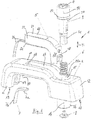
- An actuating device 1 has a handle body 2, as an actuating device a push button 3 with a lock cylinder 4, a motor driven Locking device 5, a compression spring 6 and a Cover 7 and an actuating element 8.
- the handle body 2 is viewed from the side of a substantially U-shaped handle bar with a base leg 10, a first U-leg 11 and a second U-leg 12 is formed.
- the U-legs 11, 12 each have end faces 13, with which the handle body 2, e.g. on a door outer skin of a Motor vehicle is fastened.
- the second U-leg 12 has along a leg extending in the longitudinal direction of actuation longitudinal axis 14, which also longitudinal movement axis of the push button 3 together with the lock cylinder 4 is an insertion opening 15 for the printhead 3.
- the insertion opening 15 opens into a plug-in channel 15a, the second U-leg 12 completely penetrates.
- a sleeve-shaped receiving device 16 which is a substantially cylindrical Has outer shape. From the insertion opening 15 away, extends opening into this and outwardly an elongated groove or a blind hole 17 to over about 2/3 of the base leg 10, the course of the U-leg 12 and the base leg follows.
- the blind hole 17 in the base leg 10 is in the region of its insertion opening 15 opposite End 18 just above her groove bottom with a groove recess 19 and a groove, which is open opposite or from an inner side 20 of the base leg 10 and of the first U-leg 11 up to the end face 13 of the first U-leg 11 extends in conjunction or the course of this Parts follows.
- the groove recess 19 is by means of the cover 7, which is substantially 1-shaped with a first cover leg 7a and a second cover leg 7b formed is, coverable or closable.
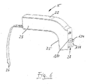
- the locking device 5 is in the manner of a plug-in module for insertion into the blind hole 17 of the handle body 2 is formed and has a rectangular cross-section Housing 21 with a housing main body 22 and a side Housing cover 23 on.
- the housing 21 is viewed from the side formed substantially L-shaped and has a first longer L-leg 24 and a shorter second L-leg 25 on.
- the first leg 24 corresponds to the SacklochausEnglishung 17 in the base leg 10.
- the second leg 25 corresponds to the blind hole 17 in the connection area this to the insertion opening 15 and comes in the assembled Condition in the transition region between the second U-leg 12 and the base leg 10 to lie. At the free end of the first leg 24 go from electrical lines 26.
- the second leg 25 has the insertion opening 15 through an outer surface 27, which is concave-cylindrical section-shaped is, such that the insertion opening 15 together with the outer surface 27 is circular in cross section. From the outside surface 27 of the locking device 5 projects on below described in more detail projecting slider 28 a piece into the insertion opening 15.
- the push button 3 has a push button top 30 and a Push button bottom 31 on.
- the push button upper part 30 sits the Lock cylinder 4 by means of a clip connection.
- a sealing ring 32 is arranged, which cooperates with the inside of the insertion opening 15 and the gap between the push button top 30 and the insertion opening 15 seals.
- the push button top 30 has a Cylinder tube section 32a and a pressure member 33.
- the cylinder tube section 32a is a thin-walled cylindrical tube with a pipe outside 34 and a free annular end face 35th Opposite to the annular end face 35 is the pressure part 33rd integrally connected to the cylinder tube section 32a.
- the Pressure part 33 is in the outer diameter relative to the cylinder tube section 32a larger and has a stepped bore 36 with the actuating longitudinal axis 14 as the central axis.
- the stepped bore 36 has inside longitudinal grooves 37 for receiving Lock plate of the lock cylinder 4. At the outer circumference has the pressure part 33 adjacent to the cylinder tube section 32 an annular groove 38 for receiving the sealing ring 32.
- the cylinder tube section 32a has opposite ones rectangular window cutouts 40 with a lower edge 41, two side edges 42 and an upper edge 43 on.
- the two Window cutouts 40 have the same areal extension.
- the lower edge 41 and the upper edge 43 are each parallel to the annular end face 35.
- the side edges 42 are parallel to the actuating longitudinal axis 14.
- the lock cylinder 4 has a locking body 50 and a Rotary body 51 on.
- the locking body 50 are in a known manner and Way locking plate 51 stored.
- the lock body 50 a guard 52 as a safeguard against falling out on, which in a known manner, a twisting of the Block body 50 in the pressure part 33 should prevent.
- the rotary body 51 has eccentrically to the actuating longitudinal axis 14 a Eccentric nipple 53, which in the axial direction of the rotary body 51 protrudes a piece down.
- the push-button base 31 has a punch portion 60 and a pipe section 61 on.
- the stamp portion 60 has along the actuating longitudinal axis 14 at the free end 62 of the stamp portion 60, a threaded hole 63 for receiving the actuating element 8 on.
- the raw section 61 has an outer diameter on, which with the inner diameter of the cylinder tube section 32a of the push button top 30 corresponds.
- the pipe section 61 extends a piece from the stamp section 60 away and corresponding to the window cutouts 40 locking projections 64, which in terms of their Room shape are dimensioned such that they are with the lower edge 41 of the window cutouts 40 can cooperate latching.
- the latching projections 64 are dimensioned such that that these are guided in the window openings 40 by the side edges 42 are movable up and down.
- the pipe section 61 Adjacent to the latching projections 64, the pipe section 61 is slightly deeper lying forehead 65 on.
- the forehead steps 65 are used for support a slider guide 66, which is detailed below is described.
- Aligned in the longitudinal direction has a the latching projections 64 as an extension of the pipe section 61st up a stop tab or stop ridge 67 on.
- the Stop tab 67 has a cylindrical tube wall portion-shaped Solid shape and has an upper free end edge 68 and Side edges 69.
- the stop tab 67 Directly in the longitudinal axis 14 adjacent to associated latching projection 64, the stop tab 67 a outwardly projecting, arcuate stepped shoulder 70, which has a circular ring-shaped step top 71.
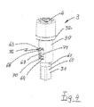
- the stepped shoulder 70 In the assembly of the push button top 30 and the Druckknopfunterteils 31 is the stepped shoulder 70 in one of the windows 40 of the pushbutton upper part 30 (see FIG 4).
- the axial extent of the stop tab 67 is such dimensioned that in the assembly, when the locking projection 64 at the lower edge 41 of the window 40 abuts, between the free Front edge 68 and the upper edge 43 is an axial distance, so that a free space or gap 72 is formed (see. FIG. 4).
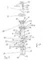
- the slide guide 66 (see Figure 3) has a substantially circular disk-shaped base plate 75, whose outer diameter approximately the inner diameter of the pipe section 60 equivalent. Opposite each other are at the base plate 75 circular disc segments 76 arranged integrally, which have an outer diameter, the outer diameter the pipe section 61 or the inner diameter of the cylinder tube section 32a corresponds.
- the circular disk sections 76 are thicker than the base plate 75 is formed and have opposing parallel, planar guide surfaces 77, which together with the base plate 75 for displaceable Storage of a slide 78, the more detailed below described serve.
- the base plate 75 forms thus together with the guide surfaces 77 in cross section U-shaped guide groove for the slider 78.
- the slider 78 is a first coupling member and has a in essential disc-shaped spatial form and has just opposite Leading edge 79, which with the guide surfaces 77 cooperate, so that a guide of the slide 78th between the circular disk sections 76 is ensured.
- the end edges of the slider 78 are circular arc. Of the Outer diameter of the slider 78 between the end edges corresponds to the inner diameter of the cylinder tube section 32a. From one of the leading edges 79 extends a U-shaped recess 80 into the interior of the slider 78. In this U-shaped recess 80 engages in the assembly of Exzen ternippel 53 of the lock cylinder 4 a. In the assembly sits the slider guide 66 with the circular disk sections 76 the forehead steps 65 of the pipe section 61.
- the slider guide 66 is with respect to the slide 78 with respect to the push button base 31 in a double arrow direction or axial direction 81 displaceable (Fig. 10), wherein the slide guide 66 along the free side edges 69 of the stop tab 67 out is.
- the housing part 22 has a side view substantially L-shaped and in cross-section U-shaped spatial form with a GeHousebodenwandung 91, a first L-shaped side wall 92 and a second L-shaped side wall 93 as well a Stirnatewandung 94.
- the second side wall 93 has in the region of the insertion opening 15, the outer surface 27th on, which together with the insertion opening 15 in cross section forms circular passage.
- the bottom wall 91 has in the region of the long leg 24 a first long Bottom wall portion 91a and in the region of the second short Leg 25 has a second short bottom wall portion 91b on.
- the bottom wall portions 91a and 91b go with a Bottom wall arch portion 91c into each other over.
- the first side wall 92 has a first long side wall portion 92a in the area of the first long leg 24, a second short side wall portion 92b in the area of the second short leg 25 and a side wall arch portion 92c in between.
- the second side wall 93 has a first long side wall portion 93a in the area of the first long leg 24, a second short Side wall portion 93b in the region of the second short Leg 25 and a side wall arch portion 93c therebetween with the first long side wall section 93a, the side wall arch portion 93c together in the assembly a flush with the surface of the handle body 2 surface form.
- the Stirnatewandung 94 is in the assembly at the free end 18 of the blind hole 17 flush.
- the front side wall 94 has two recesses 95 in the region of the side wall 92 on, through which the electrical lines 26 from the housing interior are randomlitebar.
- a motor Axial drive 100 e.g. a solenoid with a magnetic body 101 and one guided in a central bore, from the Bore outstanding piston rod 102 is arranged.
- the piston rod 102 is outside of the magnetic body 101 via a Transverse pin 103 connected to a drag lever 104, who sits in front of the head on the piston rod.
- the rocker arm 104 has in the region of its free end 105 a perpendicular to the longitudinal extension extending slot recess 106, in which a transversely extending pin 107 stored is about the drag lever 105 with a lever arm 111 of a two-armed reversing lever 108 is in communication.
- the lever 108 has a bore 109, with he on an axis 110 which extends in the region of the bottom wall arc section 91c extends vertically away from the bottom wall 91, is pivotally mounted.
- the lever 109 has a first lever arm 111 opposite the second lever arm 112 on.
- the axial drive 100, the drag lever 104 and the first lever arm 111 of the reversing lever 108 are in the range of the first leg 24 of the housing 21 is arranged.
- the second Lever arm 112 of the reversing lever 108 protrudes from the axis 110 in the second leg 25 of the housing 21.
- the lever 108 points in the region of the free end of the second lever arm 112 on an operating portion 113.
- the operating section 113 tapers towards the free end and has one Sliding surface 114, which in assembly to the insertion 15 points.
- the second bottom wall portion 91b has a rectangular, L-shaped angle groove 122 with a first short groove leg 122a and a second long groove leg 122b. Of the first groove legs 122a are parallel to the direction of actuation 120 of the axial drive 100. The second groove leg 122b runs parallel to the actuating longitudinal axis 14. At the free end of the first groove leg 122a ends in the transition region between the bottom wall portion 92c and the second side wall portion 92b of the side wall 92. Lateral alignment with the groove leg 122a is on the inside of the second sowandungsabexcellentes 92 b a stop bracket 123 for the slider 28, which will be described below, integrally formed. Opposite to the second side wall section 92b, the side wall portion 93b below the outer surface 27, a recess from which the slider 28 protrudes.
- the slider 28 is another coupling member and has a Slider plate 130 and a stop tab or stop bar 131, which is perpendicular to the slide plate 130 in the area of the one end of the slide plate 130 extending therefrom.
- the stop tab 131 has a free edge 131a on and has a width that is less than or equal to the clear width of the windows 40.
- the protrusions 132 are in assembly in the angle groove 122, i. they are standing with the angle groove legs 122a and 122b are engaged.
- the slide plate 130 In an operating position, the slide plate is located 130 on the support bracket 123 on.
- the slide plate 130 further comprises a substantially square Druchgriffs donor 133 on which the free end 113 of the reversing lever 108 passes through.
- the stop tab 131 of the slider 28 has a cylinder tube wall-shaped spatial form whose Inner diameter approximately the outer diameter of the pipe section 61 corresponds and whose outer diameter is approximately the Outer diameter of the cylinder tube portion 32a corresponds.
- a slide projection 134 which has a circular arc groove at its free end, the groove being in diameter the inner diameter of the pipe section 61 corresponds approximately.
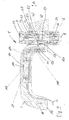
- the compression spring 6 is supported at one end Bottom wall of the receiving device 16 from and is at the other end against the annular end face 35 of the cylinder tube section 32a of the push button top 30 at.
- the push-button base 31 is axially in by means of the above-described clip connection the direction 81 slidably with the push button upper part 30 in Connection.
- the push-button upper part 30 is by means of the sealing ring 32 in the insertion opening 15 in interaction with the Outer surface 27 mounted in the handle body 2.
- the push button base 31 passes through a hole in the bottom wall of the receiving device 16 and communicates with the actuator 8 in Connection.
- the lever 108 passes through with its free End 113, the slide plate 130 of the slider 28, wherein the Slider 28 is guided in the grooves 122, 122 'in the housing 21.
- the windows 40 of the push button 3 are arranged such that the window 40 in which the stop tab 67 of the push-button base 31 is arranged, the slider 28 is opposite.
- the manually actuated via the lock cylinder 4 Slider 78 is connected to the eccentric nipple 53 of the lock cylinder 4 engaged and is by means of the eccentric nipple 53 in a direction perpendicular to the axis 14, e.g. with a key by turning the lock cylinder 4 back and forth.
- the axial drive 100 i. the solenoid below Set current so that the push rod 102 is retracted.
- the lever arm 112 of the reversing lever 110th positioned such that the sliding surface 114 parallel to the actuating longitudinal axis 14 is aligned.
- the slider 28 is seated with its guide projections 132 in the corner of the angle groove 122, so that the stop tab 131 of the slider 28 with the Stop tab 67 of the push button base 31 comes to rest and the free end edge 131a rests on the step 71.
- Farther sits the upper edge 43 of the slider 28 facing Window 40 in the push button top 30 on the slide plate 130 on.
- the push button top is 30 via the slide 28 form-fitting with the Push button bottom 31 coupled, which in turn positively connected to the actuating element 8, so that by pressing on the pressure member 33 according to FIG Push button top 30 together with the slider 28 and the Push button bottom 31 and the actuator 8 to the Length 1 is displaceable (see Figure 8).
- the slider 28 In this position is the slider 28 with its projections 132 at free end of the second groove leg 122b and 122b '.
- the Compression spring 8 is compressed. By releasing the pressure part 33 expands the compression spring 6 and spends the push button. 3 back to the starting position according to FIG 7.
- By the extension of the actuating element 8 by the length 1 becomes a Lock mechanism actuated (not shown).
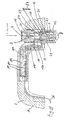
- the Push-button base remains in its initial position according to Figure 9 "stand", so that an operation of a lock mechanism (not shown) is omitted by the actuator 8, an extension of the actuating element 8 by the length of the first is thus prevented.
- Leerhub be the locking projections 64 lifted from the lower edges 41.
- the Locking projections 64 and the support projection 70 are interposed the side edges 42 of the window 40 in the cylinder tube section 32 a guided and moved relative to the push button upper part 30.
- the push button upper part by the compression spring 6 back to the starting position according to Figure 9 moved. In this position is thus an opening a motor vehicle door or the motor vehicle door (not shown) not possible because the actuator 8 from Push button shell 3 is mechanically decoupled.
- This position can be adjusted by pressing the Push button 3 reaches an actuation of the actuating element 8 be because the push button top 30 on the lock cylinder 4, the slider 78, the stop tab 67 of the push-button lower part 31 mechanically coupled to the actuator 8 is.
- an operation of the lock can also e.g. to be reached manually in case of power failure.
- the actuator according to the invention is of particular Advantage that this is particularly compact and builds both the manual closure and opening as well as a remotely operable Opening and closing possible.
- Another special The advantage is that the electrically controllable locking device 5 module or cassette-like design and in the handle body is inserted and thus in a simple way and Way a variation of the actuator with and without a remotely controlled unlocking functionality feasible is.
- the Actuator according to the invention optionally with and without a remote triggering functionality can be formed.
- An elaborate one Mounting e.g. in a door body of a motor vehicle, as is usually done, is eliminated.
Landscapes
- Lock And Its Accessories (AREA)
Abstract
Description
- Figur 1:
- eine perspektivische Explosionsdarstellung einer erfindungsgemäßen Betätigungsvorrichtung;
- Figur 2:
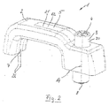
- die Betätigungsvorrichtung gemäß Figur 1 in einer perspektivischen Zusammenbaudarstellung;
- Figur 3:
- eine perspektivische Explosionsdarstellung eines Druckknopfes der Betätigungsvorrichtung gemäß Figur 1;
- Figur 4:
- eine perspektivische Zusammenbaudarstellung des Druckknopfes gemäß Figur 3;
- Figur 5:
- eine perspektivische Explosionsdarstellung einer Verriegelungseinrichtung der erfindungsgemäßen Betätigungsvorrichtung gemäß Figur 1;
- Figur 6:
- die Verriegelungseinrichtung gemäß Figur 5 in einer perspektivischen Zusammenbaudarstellung;
- Figur 7:
- einen Längsschnitt durch die Betätigungsvorrichtung gemäß Figur 1 in einer ersten Betriebsstellung mit nichtbetätigtem Druckknopf;
- Figur 8:
- die Betätigungsvorrichtung gemäß Figur 7 mit betätigtem Druckknopf;
- Figur 9:
- einen Längsschnitt durch die erfindungsgemäße Betätigungsvorrichtung in einer zweiten Betriebsstellung mit nicht nichtbetätigtem Druckknopf;
- Figur 10
- die Betätigungsvorrichtung gemäß Figur 9 mit betätigtem Druckknopf.
Claims (64)
- Betätigungsvorrichtung für eine Schlossmechanik, insbesondere einer Tür oder Klappe eines Kraftfahrzeuges insbesondere eines Traktors mit einem Griffkörper (2), in dem in einem Griffkörperendbereich eine Betätigungseinrichtung (3, 30, 31) zum Antrieb eines Betätigungselements (8) für die Schlossmechanik gelagert ist, wobei ein bewegliches Koppelglied (28) vorgesehen ist, mit dem die Betätigungseinrichtung (3, 30, 31) außer Funktion bringbar ist, dadurch gekennzeichnet dass das Koppelglied (28) mit einer eine fernbedienbare Antriebseinrichtung (100) aufweisenden Verriegelungseinrichtung (5) antreibbar in Verbindung steht und die Verriegelungseinrichtung (5) in anderen Teilbereichen des Griffkörpers (2) untergebracht ist.
- Betätigungsvorrichtung nach Anspruch 1, gekennzeichnet durch ein weiteres manuell betätigbares Koppelglied (78).
- Betätigungsvorrichtung nach Anspruch 1 und/oder 2, dadurch gekennzeichnet, dass die Antriebseinrichtung (100) ein Axialantrieb (100) insbesondere ein Hubmotor, vorzugsweise ein Hubmagnetantrieb ist.
- Betätigungsvorrichtung nach einem oder mehreren der vorangegangenen Ansprüche, dadurch gekennzeichnet, dass die Antriebseinrichtung (100) über einen schwenkbaren Umlenkhebel (108) mit dem Koppelglied (28) verbunden ist.
- Betätigungsvorrichtung nach einem oder mehreren der vorangegangenen Ansprüche, dadurch gekennzeichnet, dass zwischen dem Umlenkhebel (108) und der Antriebseinrichtung (100) ein Schlepparm (104) zwischengeschaltet ist.
- Betätigungsvorrichtung nach einem oder mehreren der vorangegangenen Ansprüche, dadurch gekennzeichnet, dass die Antriebseinrichtung (100) mit Hebelarm (108) und gegebenenfalls Schlepparm (104) sowie das Koppelglied (28) in einem Gehäuse (21) untergebracht sind und dass das Gehäuse (21) im Griffkörper angeordnet ist.
- Betätigungsvorrichtung nach einem oder mehreren der vorangegangenen Ansprüche, dadurch gekennzeichnet, dass die Betätigungseinrichtung einen Druckknopf (3) mit einem Schließzylinder (4) aufweist.
- Betätigungsvorrichtung nach einem oder mehreren der vorangegangenen Ansprüche, gekennzeichnet durch den Griffkörper (2), den Druckknopf (3) mit dem Schließzylinder (4), die motorisch antreibbare Verriegelungseinrichtung (5), und ein mit einer Druckfeder (6) beaufschlagtes Betätigungselement (8).
- Betätigungsvorrichtung nach einem oder mehreren der vorangegangenen Ansprüche, dadurch gekennzeichnet, dass der Griffkörper (2) im Wesentlichen U-förmig, mit einen Basisschenkel (10), einem ersten U-Schenkel (11) und einem zweiten U-Schenkel (12) ausgebildet ist, wobei die U-Schenkel (11, 12) jeweils Stirnseiten (13) aufweisen, mit denen der Griffkörper (2) z.B. an einer Türaußenhaut befestigbar ist.
- Betätigungsvorrichtung nach einem oder mehreren der vorangegangenen Ansprüche, dadurch gekennzeichnet, dass der zweite U-Schenkel (12) entlang einer Betätigungslängsachse (14) eine Einstecköffnung (15) für den Druckknopf (3) aufweist.
- Betätigungsvorrichtung nach einem oder mehreren der vorangegangenen Ansprüche, dadurch gekennzeichnet, dass die Einstecköffnung (15) den zweiten U-Schenkel (12) vollständig durchdringt und sich von der Stirnseite (13) des zweiten U-Schenkels eine Aufnahmeeinrichtung (16) mit einer im Wesentlichen zylindrischen Außenform wegerstreckt.
- Betätigungsvorrichtung nach einem oder mehreren der vorangegangenen Ansprüche, dadurch gekennzeichnet, dass sich von der Einstecköffnung (15) weg in diese mündend eine längliche Sacklochausnehmung (17) bis über etwa 1/3 des Basisschenkels (10) des Griffkörpers (2) erstreckt und diese im Bereich ihres der Einstecköffnung (15) gegenüberliegenden Endes mit einer Nutvertiefung (19), welche sich von einer Innenseite des Basisschenkels (10) und des ersten U-Schenkels (11) bis hin zur Stirnseite (13) des ersten U-Schenkels (11) erstreckt, in Verbindung steht.
- Betätigungsvorrichtung nach einem oder mehreren der vorangegangenen Ansprüche, dadurch gekennzeichnet, dass die Nutvertiefung (19) mittels der Abdeckung (7), welche im Wesentlichen L-förmig mit einem ersten Abdeckungsschenkel (7a) und einem zweiten Abdeckungsschenkel (7b) ausgebildet ist, abdeckbar bzw. verschließbar ist.
- Betätigungsvorrichtung nach einem oder mehreren der vorangegangenen Ansprüche, dadurch gekennzeichnet, dass die Verriegelungseinrichtung (5) nach Art eines Einsteckmoduls zum Einstecken die Sacklochausnehmung (17) des Griffkörpers (2) ausgebildet ist und ein Gehäuse (21) mit einem Gehäuseteil (22) und einem Gehäusedeckel (23) aufweist.
- Betätigungsvorrichtung nach einem oder mehreren der vorangegangenen Ansprüche, dadurch gekennzeichnet, dass das Gehäuse (21) im wesentlichen L-förmig ausgebildet ist und einen ersten Schenkel (24) und einen zweiten Schenkel (25) aufweist.
- Betätigungsvorrichtung nach einem oder mehreren der vorangegangenen Ansprüche, dadurch gekennzeichnet, dass der erste Schenkel (24) mit der Sacklochausnehmung (17) im Basisschenkel (10) korrespondiert und der zweite Schenkel (25) mit der Sacklochausnehmung (17) im Anschlussbereich dieser zur Einstecköffnung (15) korrespondiert.
- Betätigungsvorrichtung nach einem oder mehreren der vorangegangenen Ansprüche, dadurch gekennzeichnet, dass am freien Ende des ersten Schenkels (24) elektrische Leitungen (26) zu einem elektrischen Steuerelement abgehen.
- Betätigungsvorrichtung nach einem oder mehreren der vorangegangenen Ansprüche, dadurch gekennzeichnet, dass der zweite Schenkel (25) zur Einstecköffnung (15) hin eine Außenfläche (27) aufweist, welche zylinderabschnittsförmig ausgebildet ist, derart, dass die Einstecköffnung (15) zusammen mit der Außenfläche (27) im Querschnitt kreisförmig ist, wobei aus der Außenfläche (27) der Verriegelungseinrichtung (5) der Schieber (28) ein Stück in die Einstecköffnung (15) hineinragt.
- Betätigungsvorrichtung nach einem oder mehreren der vorangegangenen Ansprüche, dadurch gekennzeichnet, dass der Druckknopf (3) ein Druckknopfoberteil (30) und ein Druck knopfunterteil (31) aufweist, wobei im Druckknopfoberteil (30) der Schließzylinder (4) mittels einer Clipsverbindung eingesetzt ist.
- Betätigungsvorrichtung nach einem oder mehreren der vorangegangenen Ansprüche, dadurch gekennzeichnet, dass das Druckknopfoberteil (30) einen Dichtring (32) aufweist, welcher mit der Innenseite der Einstecköffnung (15) zusammenwirkt und den Spalt zwischen den Druckknopfoberteil (30) und der Einstecköffnung (15) abdichtet.
- Betätigungsvorrichtung nach einem oder mehreren der vorangegangenen Ansprüche, dadurch gekennzeichnet, dass das Druckknopfoberteil einen Zylinderrohrabschnitt (32a) und ein Druckteil (33) aufweist, wobei der Zylinderrohrabschnitt (32a) ein dünnwandiges zylindrisches Rohr mit einer Rohraußenseite (34) und einer freien Ringstirnfläche (35) ist, und gegenüberliegend zur Ringstirnfläche (35) das Druckteil (33) einstückig mit dem Zylinderrohrabschnitt (32a) verbunden ist.
- Betätigungsvorrichtung nach einem oder mehreren der vorangegangenen Ansprüche, dadurch gekennzeichnet, dass das Druckteil (33) im Außendurchmesser gegenüber dem Zylinderrohrabschnitt (32a) größer ist und eine Stufenbohrung (36) mit der Betätigungslängsachse (14) als Mittelachse aufweist, wobei die Stufenbohrung (36) innenseitig Nuten (27) zur Aufnahme von Schließplättchen des Schließzylinders (4) aufweist.
- Betätigungsvorrichtung nach einem oder mehreren der vorangegangenen Ansprüche, dadurch gekennzeichnet, dass der Zylinderrohrabschnitt (32a) sich jeweils gegenüberliegende Fensterausschnitte(40) mit einer Unterkante (41), zwei Seitenkanten (42) und eine Oberkante (43) aufweist, wobei die beiden Fensterausschnitte (40) die gleiche flächenmäßigen Erstreckung haben und die Unterkante (41) und die Oberkante (43) jeweils parallel zur Ringsternfläche (35) angeordnet sind, wobei die Seitenkanten (42) parallel zur Betätigungslängsachse (14) angeordnet sind.
- Betätigungsvorrichtung nach einem oder mehreren der vorangegangenen Ansprüche, dadurch gekennzeichnet, dass der Schließzylinder (4) einen Sperrkörper (50) und einen Drehkörper (51) aufweist, wobei im Sperrkörper (50) Schließplättchen (51) gelagert sind und der Sperrkörper (50) einen Verdrehvorsprung (52) aufweist.
- Betätigungsvorrichtung nach einem oder mehreren der vorangegangenen Ansprüche, dadurch gekennzeichnet, dass der Drehkörper (51) exzentrisch zur Betätigungslängsachse (14) einen Exzenternippel (53) aufweist, welcher in Axialrichtung vom Drehkörper (51) ein Stück vorsteht.
- Betätigungsvorrichtung nach einem oder mehreren der vorangegangenen Ansprüche, dadurch gekennzeichnet, dass das Druckknopfunterteil (31) einen Stempelabschnitt (60) und einen Rohrabschnitt (61) aufweist, wobei der Stempelabschnitt (60) entlang der Betätigungslängsachse (14) am freien Ende (62) des Stempelabschnitts (60) eine Gewindebohrung (63) zur Aufnahme des Betätigungselements (8) aufweist und der Rohrabschnitt (61) einen Außendurchmesser aufweist, welcher mit dem Innendurchmesser des Zylinderrohrabschnitts (36a) des Druckknopfoberteils (30) korrespondiert.
- Betätigungsvorrichtung nach einem oder mehreren der vorangegangenen Ansprüche, dadurch gekennzeichnet, dass der Rohrabschnitt (61) sich ein Stück vom Stempelabschnitt (60) wegerstreckt und korrespondierend zu den Fensteraus schnitten (40) Rastvorsprünge (64) aufweist, welche hinsichtlich ihrer Raumform derart bemessen sind, dass sie mit der Unterkante (41) der Fensterausschnitte (40) zusammenwirken können.
- Betätigungsvorrichtung nach einem oder mehreren der vorangegangenen Ansprüche, dadurch gekennzeichnet, dass hinsichtlich der Breite die Rastvorsprünge (64) derart bemessen sind, dass diese in den Fensterausschnitten (40), geführt durch die Seitenkanten (42) auf und ab bewegbar sind.
- Betätigungsvorrichtung nach einem oder mehreren der vorangegangenen Ansprüche, dadurch gekennzeichnet, dass benachbart zu den Rastvorsprüngen (64) der Rohrabschnitt (61) etwas tieferliegend Stirnstufen (65) aufweist, wobei die Stirnstufen (65) zur Auflage einer Schieberführung (66) dienen.
- Betätigungsvorrichtung nach einem oder mehreren der vorangegangenen Ansprüche, dadurch gekennzeichnet, dass in Längsrichtung fluchtend einer der Rastvorsprünge (64) als Verlängerung des Rohrabschnitts (61) einen Anschlaglappen (67) aufweist, wobei der Anschlaglappen eine zylinderrohrabschnittsförmige Raumform aufweist und eine freie Stirnkante (68) und Seitenkanten (69) besitzt.
- Betätigungsvorrichtung nach einem oder mehreren der vorangegangenen Ansprüche, dadurch gekennzeichnet, dass direkt in Längsrichtung (14) benachbart zum zugehörigen Rastvorsprung (64) der Anschlaglappen (67) einen Stufenabsatz (70) aufweist, welcher eine kreisringabschnittsförmige Stufenoberseite (71) besitzt.
- Betätigungsvorrichtung nach einem oder mehreren der vorangegangenen Ansprüche, dadurch gekennzeichnet, dass im Zusammenbau des Druckknopfoberteils (30) und des Druckknopfunterteils (31) sich der Stufenabsatz (70) in einem der Fenster (40) des Druckknopfoberteils (30) befindet.
- Betätigungsvorrichtung nach einem oder mehreren der vorangegangenen Ansprüche, dadurch gekennzeichnet, dass die axiale Erstreckung des Anschlaglappens (67) derart bemessen ist, dass im Zusammenbau, wenn der Rastvorsprung (64) an der Unterkante (41) des Fensters (40) anliegt, zwischen der freien Stirnkante (68) und der Oberkante (43) ein axialer Abstand vorliegt, so dass ein Spalt (72) gebildet ist.
- Betätigungsvorrichtung nach einem oder mehreren der vorangegangenen Ansprüche, dadurch gekennzeichnet, dass die Schieberführung (66) eine im Wesentlichen kreisscheibenförmige Grundplatte (75) aufweist, deren Außendurchmesser in etwa dem Innendurchmesser (60) entspricht und gegenüberliegend beabstandet zueinander an die Grundplatte (75) Kreisscheibensegmente (76) einstückig angeformt sind.
- Betätigungsvorrichtung nach einem oder mehreren der vorangegangenen Ansprüche, dadurch gekennzeichnet, dass die Kreisscheibenabschnitte (76) dicker als die Grundplatte (75) ausgebildet sind und gegenüberliegende parallele Führungsflächen (77) aufweisen, welche zusammen mit der Grundplatte (75) zur verschieblichen Lagerung des Schiebers (78) dienen.
- Betätigungsvorrichtung nach einem oder mehreren der vorangegangenen Ansprüche, dadurch gekennzeichnet, dass der Schieber (78) eine im Wesentlichen kreisscheibenförmige Raumform aufweist und abgeflachte gegenüberliegende Stirnkanten (79) hat, welche mit den Führungsflächen (77) zusammenwirken, so dass eine Führung des Schiebers (79) zwischen den Kreisscheibenabschnitten (76) gewährleistet ist.
- Betätigungsvorrichtung nach einem oder mehreren der vorangegangenen Ansprüche, dadurch gekennzeichnet, dass von einer der Abflachungen (79) eine U-förmige Ausdehnung (80) ins Innere des Schiebers (78) erstreckt und in diese U-förmige Ausnehmung (80) im Zusammenbau der Exzenternippel (53) des Schließzylinders (4) eingreift.
- Betätigungsvorrichtung nach einem oder mehreren der vorangegangenen Ansprüche, dadurch gekennzeichnet, dass das Gehäuseteil (22) eine im Wesentlichen L-förmige, rinnenförmige Raumform mit einer Gehäusebodenwandung (91) einer ersten L-förmigen Seitenwandung (92) und einer zweiten L-förmigen Seitenwandung (93) sowie einer Stirnseitenwandung (94) aufweist, wobei die zweite Seitenwandung (93) im Bereich der Einstecköffnung (15) die Außenfläche (27) aufweist.
- Betätigungsvorrichtung nach einem oder mehreren der vorangegangenen Ansprüche, dadurch gekennzeichnet, dass die Bodenwandung (91) im Bereich des ersten Schenkels (24) einen ersten Bodenwandungsabschnitt (91a) und im Bereich des zweiten Schenkels (25) einen zweiten Bodenwandungsabschnitt (91b) aufweist, welche mit einem Bodenwandungsbogenabschnitt (91c) verbunden sind.
- Betätigungsvorrichtung nach einem oder mehreren der vorangegangenen Ansprüche, dadurch gekennzeichnet, dass die erste Seitenwandung (92) einen ersten Seitenwandungsabschitt (92a) im Bereich des ersten Schenkels (24), einen zweiten Seitenwandungsabschnitt (92b) im Bereich des zweiten Schenkels (25) und einen Seitenwandungsbogenabschnitt (92c) dazwischen aufweist.
- Betätigungsvorrichtung nach einem oder mehreren der vorangegangenen Ansprüche, dadurch gekennzeichnet, dass die zweite Seitenwandung (93) einen ersten Seitenwandungsabschnitt (93a) im Bereich des ersten Schenkels (24), einen zweiten Seitenwandungsabschnitt (93b) im Bereich des zweiten Schenkels (25) und einen Seitenwandungsbogenabschnitt (93c) dazwischen aufweist, wobei der erste Seitenwandungsabschnitt (93a) und der Seitenwandungsbogenabschnitt (93c) zusammen im Zusammenbau eine mit der Oberfläche des Griffkörpers (2) fluchtende Fläche bilden.
- Betätigungsvorrichtung nach einem oder mehreren der vorangegangenen Ansprüche, dadurch gekennzeichnet, dass im Bereich des ersten Schenkels der motorische Axialantrieb (100) angeordnet ist, welcher ein Hubmagnet mit einem Magnetkörper (101) und einer Kolgenstange (102) ist, die Kolbenstange (102) über einen Querstift (103) mit einem Schlepphebel (104) verbunden ist.
- Betätigungsvorrichtung nach einem oder mehreren der vorangegangenen Ansprüche, dadurch gekennzeichnet, dass der Schlepphebel (104) im Bereich seines freien Endes (105) eine Langlochausnehmung (106) aufweist, in der ein Stift (107) gelagert ist, über dem der Schlepphebel (5) mit einem Umlenkhebel (108) in Verbindung steht, wobei der Umlenkhebel (108) eine Bohrung (109) aufweist, mit der er auf einer Achse (110), welche sich im Bereich des Bodenwandungsbogenabschnitts (91c) vertikal von der Bodenwandung (91) wegerstreckt, schwenkbar gelagert ist.
- Betätigungsvorrichtung nach einem oder mehreren der vorangegangenen Ansprüche, dadurch gekennzeichnet, dass der Umlenkhebel (109) einen ersten Hebelarm (111) und einen zweiten Hebelarm (112) aufweist, wobei der zweite Hebelarm (112) des Umlenkhebels (108) von der Achse (110) aus in den zweiten Schenkel (25) des Gehäuses (21) ragt.
- Betätigungsvorrichtung nach einem oder mehreren der vorangegangenen Ansprüche, dadurch gekennzeichnet, dass bei Axialantrieb (100), der Schlepphebel (104) und der Hebelarm (111) des Umlenkhebels (108) im Bereich des ersten Schenkels 24 des Gehäuses (21) angeordnet sind.
- Betätigungsvorrichtung nach einem oder mehreren der vorangegangenen Ansprüche, dadurch gekennzeichnet, dass der Umlenkhebel (108) im Bereich des freien Endes des zweiten Hebelarmes (112) einen Betätigungsabschnitt (113) aufweist, wobei sich der Betätigungsabschnitt (113) zum freien Ende hin verjüngt und eine Gleitfläche (114) aufweist, welche im Zusammenbau zur Einstecköffnung (15) weist.
- Betätigungsvorrichtung nach einem oder mehreren der vorangegangenen Ansprüche, dadurch gekennzeichnet, dass der zweite Bodenwandungsabschnitt (91b) eine Winkelnut (122) mit einem ersten Nutschenkel (122a) und einem zweiten Nutschenkel (122b) aufweist, wobei der erste Nutschenkel (122a) parallel zur Betätigungsrichtung (120) des Axialantriebs (100) verläuft und der zweite Nutschenkel (122b) parallel zur Betätigungslängsachse (14) verläuft.
- Betätigungsvorrichtung nach einem oder mehreren der vorangegangenen Ansprüche, dadurch gekennzeichnet, dass am freien Ende des ersten Nutschenkels (122a) dieser im Übergangsbereich zwischen dem Bodenwandungsabschnitt (92c) und dem zweiten Seitenwandungsabschnitt (92b) der Seitenwandung (92) endet.
- Betätigungsvorrichtung nach einem oder mehreren der vorangegangenen Ansprüche, dadurch gekennzeichnet, dass fluchtend mit dem Nutschenkel (122a) an der Innenseite des zweiten Seitenwandungsabschnittes (92b) eine Anschlagkonsole (123) für den Schieber (28) angeordnet ist.
- Betätigungsvorrichtung nach einem oder mehreren der vorangegangenen Ansprüche, dadurch gekennzeichnet, dass gegenüberliegend zum zweiten Seitenwandungsabschnitt (92b) der Seitenwandungsabschnitt (93b) unterhalb der Außenfläche (27) eine Ausnehmung aufweist, aus der der Schieber (28) hervorragt.
- Betätigungsvorrichtung nach einem oder mehreren der vorangegangenen Ansprüche, dadurch gekennzeichnet, dass der Schieber (28) eine Schieberplatte (130) und einen Anschlaglappen (131) aufweist, welcher sich vertikal von der Schieberplatte (130) im Bereich des einen Endes der Schieberplatte (130) vertikal von diesem wegerstreckt.
- Betätigungsvorrichtung nach einem oder mehreren der vorangegangenen Ansprüche, dadurch gekennzeichnet, dass der Anschlaglappen (131) eine freie Kante (131a) aufweist und eine Breite hat, die kleiner oder gleich ist der lichten Weite der Fenster (40).
- Betätigungsvorrichtung nach einem oder mehreren der vorangegangenen Ansprüche, dadurch gekennzeichnet, dass im Bereich des anderen Endes der Schieberplatte (130) an die Schieberplatte (130) Vorsprünge angeformt sind, welche im Zusammenbau in der Winkelnut (122) laufen.
- Betätigungsvorrichtung nach einem oder mehreren der vorangegangenen Ansprüche, dadurch gekennzeichnet, dass gegenüberliegend zur Winkelnut (122) in der Bodenwandung (91) im Deckel (23) ebenfalls eine Winkelnut (122') mit einem ersten Winkelnutschenkel (122a') und einem zweiten Winkelnutschenkel (122b') eingeformt ist.
- Betätigungsvorrichtung nach einem oder mehreren der vorangegangenen Ansprüche, dadurch gekennzeichnet, dass die Schieberplatte (130) ein im Wesentlichen quadratisches Durchgriffsfenster (133) aufweist, welches das freie Ende (113) des Umlenkhebels (108) durchgreift.
- Betätigungsvorrichtung nach einem oder mehreren der vorangegangenen Ansprüche, dadurch gekennzeichnet, dass in Verlängerung der Schieberplatte (130) sich über den Anschlaglappen (131) hinaus ein Schiebervorsprung (134) erstreckt, welcher an seinem freien Ende eine kreisbogenförmige Auskehlung besitzt.
- Betätigungsvorrichtung nach einem oder mehreren der vorangegangenen Ansprüche, dadurch gekennzeichnet, dass das Gehäuse (21), in dem der Axialantrieb (100), der Schlepphebel (104), der Umlenkhebel (108) und der Schieber (28) gelagert sind, die Verriegelungseinrichtung (5) bilden, welche modul- bzw. kassettenartig in den Griffkörper (2) einsetzbar ist.
- Betätigungsvorrichtung nach einem oder mehreren der vorangegangenen Ansprüche, dadurch gekennzeichnet, dass die Druckfeder (6) einendig an eine Bodenwandung der Aufnahmeeinrichtung (16) anliegt und anderendig mit der Ringstirnfläche (35) des Zylinderrohrabschnitts (32a) des Druckknopfoberteils (30) in Verbindung steht.
- Betätigungsvorrichtung nach einem oder mehreren der vorangegangenen Ansprüche, dadurch gekennzeichnet, dass das Druckknopfunterteil (31) mittels einer Clipsverbindung mit dem Druckknopfoberteil (30) zueinander axial in der Richtung (81) verschiebbar verbunden ist.
- Betätigungsvorrichtung nach einem oder mehreren der vorangegangenen Ansprüche, dadurch gekennzeichnet, dass das Druckknopfoberteil (30) mittels des Dichtrings (32) und der Einstecköffnung (15) im Zusammenspiel mit der Außenfläche (27) im Griffkörper (2) gelagert ist.
- Betätigungsvorrichtung nach einem oder mehreren der vorangegangenen Ansprüche, dadurch gekennzeichnet, dass das Druckknopfunterteil (31) eine Bohrung in der Bodenwandung der Aufnahmeeinrichtung (16) durchgreift und mit dem Betätigungselement (8) in Verbindung steht.
- Betätigungsvorrichtung nach einem oder mehreren der vorangegangenen Ansprüche, dadurch gekennzeichnet, dass der Umlenkhebel (108) mit seinem freien Ende (113) die Schieberplatte (130) des Schiebers (28) durchgreift, wobei der Schieber (28) in den Nuten (122, 122') im Gehäuse (21) geführt ist.
- Betätigungsvorrichtung nach einem oder mehreren der vorangegangenen Ansprüche, dadurch gekennzeichnet, dass die Fenster (40) des Druckknopfes (3) derart angeordnet sind, dass das Fenster (40), in welchem der Anschlaglappen (67) des Druckkopfunterteils (31) angeordnet ist, dem Schieber (28) gegenüberliegt.
- Betätigungsvorrichtung nach einem oder mehreren der vorangegangenen Ansprüche, dadurch gekennzeichnet, dass der Schieber (78) mit dem Exzenternippel (53) des Schließzylinders (4) im Eingriff steht und mit diesem verschiebbar ist.
Applications Claiming Priority (2)
| Application Number | Priority Date | Filing Date | Title |
|---|---|---|---|
| DE200410009366 DE102004009366A1 (de) | 2004-02-26 | 2004-02-26 | Betätigungsvorrichtung für ein Schloss |
| DE102004009366 | 2004-02-26 |
Publications (2)
| Publication Number | Publication Date |
|---|---|
| EP1568832A2 true EP1568832A2 (de) | 2005-08-31 |
| EP1568832A3 EP1568832A3 (de) | 2007-06-06 |
Family
ID=34745285
Family Applications (1)
| Application Number | Title | Priority Date | Filing Date |
|---|---|---|---|
| EP20050101413 Withdrawn EP1568832A3 (de) | 2004-02-26 | 2005-02-24 | Betätigungsvorrichtung für ein schloss |
Country Status (3)
| Country | Link |
|---|---|
| US (1) | US7194881B2 (de) |
| EP (1) | EP1568832A3 (de) |
| DE (1) | DE102004009366A1 (de) |
Cited By (3)
| Publication number | Priority date | Publication date | Assignee | Title |
|---|---|---|---|---|
| WO2007025644A1 (de) * | 2005-08-30 | 2007-03-08 | D. la Porte Söhne GmbH | Betätigungsvorrichtung für ein schloss |
| US7819440B2 (en) | 2007-01-31 | 2010-10-26 | Tri/Mark Corporation | Power locking handle for a movable closure element |
| CN113802932A (zh) * | 2020-06-15 | 2021-12-17 | 赖晋华 | 高安全性电子机械码盘安全锁 |
Families Citing this family (13)
| Publication number | Priority date | Publication date | Assignee | Title |
|---|---|---|---|---|
| CN2863548Y (zh) * | 2005-12-29 | 2007-01-31 | 明门实业股份有限公司 | 扶手装置 |
| DE202006003304U1 (de) * | 2006-03-02 | 2007-07-05 | Dirak Dieter Ramsauer Konstruktionselemente Gmbh & Co. Kg | Griff mit Verschlußeinsatz |
| DE102006032257B4 (de) * | 2006-07-12 | 2010-02-11 | D. la Porte Söhne GmbH | Drehfallenschloss |
| ES2331500B2 (es) * | 2007-10-25 | 2010-08-27 | Ojmar, S.A. | Cerradura de cierre electronico programable, con pomo movil. |
| ES2384284T3 (es) * | 2008-07-02 | 2012-07-03 | Ojmar S.A. | Cerradura electrónica programable |
| US8756963B2 (en) * | 2012-07-13 | 2014-06-24 | S.P.E.P. Acquisition Corp. | Sealed push button latch |
| USD708924S1 (en) | 2013-05-09 | 2014-07-15 | Trimark Corporation | Pull handle with integrated keypad |
| US9441403B2 (en) | 2013-05-15 | 2016-09-13 | Trimark Corporation | Power locking door handles with integrated keypad |
| US9145712B1 (en) * | 2014-12-17 | 2015-09-29 | I-Tek Metal Mfg. Co., Ltd. | Lock cylinder for a door lock |
| CN207027350U (zh) * | 2017-05-26 | 2018-02-23 | 上海蔚来汽车有限公司 | 用于安装平面车门外把手的定位工装 |
| GB2587770B (en) | 2019-04-08 | 2022-09-21 | Trimark Europe Ltd | A remotely operable push button lock mechanism |
| USD1043306S1 (en) | 2023-03-13 | 2024-09-24 | Trimark Corporation | Push button handle |
| USD1068434S1 (en) * | 2024-01-11 | 2025-04-01 | Graco Minnesota Inc. | Handle |
Family Cites Families (19)
| Publication number | Priority date | Publication date | Assignee | Title |
|---|---|---|---|---|
| US2358554A (en) * | 1943-03-02 | 1944-09-19 | American Telephone & Telegraph | Lock mechanism |
| DE925154C (de) * | 1952-07-03 | 1955-03-14 | Wilhelm Nolte | Vorrichtung zum Sichern von Tueren, insbesondere Kraftwagentueren, gegen unbefugtes OEffnen |
| DE1022117B (de) * | 1952-07-18 | 1958-01-02 | Wilhelm Nolte | Vorrichtung zum Sichern von Tueren, insbesondere Kraftwagentueren, gegen unbefugtes OEffnen |
| US3036453A (en) * | 1958-03-17 | 1962-05-29 | Expl De Brevets D App Electron | Push-button operator |
| DE1109053B (de) * | 1958-03-17 | 1961-06-15 | Expl De Brevets D App Electron | Druckknopf zum Betaetigen mechanischer Teile, insbesondere von Fallen von Verschluessen, mit einem angebauten Elektromagneten |
| JPS5189624A (en) * | 1975-01-31 | 1976-08-05 | Rotsukusochino enkakuseigyosochi | |
| US4936122A (en) * | 1985-06-04 | 1990-06-26 | Shunichi Osada | Electronic door lock assembly |
| US4886310A (en) * | 1988-06-20 | 1989-12-12 | General Motors Corporation | Door handle for vehicle with flush glass |
| US5040390A (en) * | 1989-11-16 | 1991-08-20 | General Motors Corporation | Lock and control assembly for a vehicle tailgate |
| FR2769037B1 (fr) * | 1997-10-01 | 1999-11-19 | Valeo Securite Habitacle | Dispositif de verrouillage comportant un doigt de transmission commande par came |
| DE19746381C1 (de) * | 1997-10-21 | 1999-01-21 | Huf Huelsbeck & Fuerst Gmbh | Verschlußvorrichtung mit einem schlüsselbetätigbaren Schließzylinder, der zugleich als Druckhandhabe zum Betätigen von Schloßgliedern dient |
| US6826935B2 (en) * | 1997-12-22 | 2004-12-07 | Security People, Inc. | Mechanical/electronic lock and key therefor |
| IT1305155B1 (it) * | 1998-11-03 | 2001-04-10 | Valeo Sicurezza Abitacolo Spa | Maniglia per una porta di un veicolo. |
| US6240751B1 (en) * | 1999-04-16 | 2001-06-05 | Tri/Mark Corporation | Operator for a latch system |
| WO2001040606A1 (de) * | 1999-11-29 | 2001-06-07 | Robert Bosch Gmbh | Kraftfahrzeug-türschliesssystem |
| CA2297333A1 (en) * | 2000-01-27 | 2001-07-27 | Christian Doucet | Pressure biased clutch mechanism for locks |
| DE10121046A1 (de) * | 2001-04-28 | 2002-11-07 | Huf Huelsbeck & Fuerst Gmbh | Außenbetätigung für Fahrzeugschlösser von Türen, Klappen oder dgl. |
| JP3619505B2 (ja) * | 2001-11-20 | 2005-02-09 | 株式会社ホンダロック | 車両用ドアのハンドル装置 |
| EP1582670B1 (de) * | 2004-03-30 | 2010-06-16 | Kabushiki Kaisha Honda Lock | Türgriffanordnung für eine Kraftfahrzeugtür |
-
2004
- 2004-02-26 DE DE200410009366 patent/DE102004009366A1/de not_active Withdrawn
-
2005
- 2005-02-24 EP EP20050101413 patent/EP1568832A3/de not_active Withdrawn
- 2005-02-25 US US11/063,345 patent/US7194881B2/en not_active Expired - Fee Related
Cited By (3)
| Publication number | Priority date | Publication date | Assignee | Title |
|---|---|---|---|---|
| WO2007025644A1 (de) * | 2005-08-30 | 2007-03-08 | D. la Porte Söhne GmbH | Betätigungsvorrichtung für ein schloss |
| US7819440B2 (en) | 2007-01-31 | 2010-10-26 | Tri/Mark Corporation | Power locking handle for a movable closure element |
| CN113802932A (zh) * | 2020-06-15 | 2021-12-17 | 赖晋华 | 高安全性电子机械码盘安全锁 |
Also Published As
| Publication number | Publication date |
|---|---|
| US7194881B2 (en) | 2007-03-27 |
| DE102004009366A1 (de) | 2005-09-15 |
| EP1568832A3 (de) | 2007-06-06 |
| US20050279144A1 (en) | 2005-12-22 |
Similar Documents
| Publication | Publication Date | Title |
|---|---|---|
| EP2037063B1 (de) | Verriegelungssystem für eine Tür | |
| EP1568832A2 (de) | Betätigungsvorrichtung für ein schloss | |
| EP0861959B1 (de) | Sicherheitsschloss mit Zugangskontrolle | |
| DE102008018500A1 (de) | Kraftfahrzeugschloß | |
| WO2007104499A2 (de) | Verriegelungssystem für eine tür | |
| EP3165703A2 (de) | Absenkbare dichtungsvorrichtung | |
| DE29506151U1 (de) | Sicherungsvorrichtung für ein auf eine Montagefläche montierbares Schaltgerät mit Schaltschloß | |
| DE19514742A1 (de) | Rohrrahmenschloß | |
| DE102016108706A1 (de) | Standflügelschloss mit Motorantrieb | |
| DE19534609C2 (de) | Selbstverriegelndes Motorschloss | |
| EP2441905B1 (de) | Schloss | |
| EP1920126B1 (de) | Betätigungsvorrichtung für ein schloss | |
| EP1629166A1 (de) | Kraftfahrzeugtürverschluss | |
| EP3045624A1 (de) | Verriegelungsvorrichtung für einen schwenkbar gelagerten flügel | |
| DE4013158C1 (en) | Roller blind covering car boot - incorporates swing arm passing through blind casing and pushbutton control | |
| EP1790810A2 (de) | Türblattintegrierbarer Türstopper | |
| EP0328780A2 (de) | Stellelement zur Entriegelung, Verriegelung und Einbruchsicherung eines Tür- oder Klappenschlosses | |
| EP1739257B1 (de) | Schloss | |
| EP3438384A1 (de) | Schloss | |
| DE202005021438U1 (de) | Betätigungsvorrichtung für ein Schloss | |
| DE102014215174A1 (de) | Treibstangenschloss | |
| EP3215696B1 (de) | Schloss | |
| EP1231345B1 (de) | Gesteuerte Verriegelungsvorrichtung und Eckumlenkung | |
| DE102005020194B4 (de) | Anordnung eines Riegelschlosses mit einem Verschluß-Gegenstück an einer Möbeltür | |
| EP3339540B1 (de) | Schloss |
Legal Events
| Date | Code | Title | Description |
|---|---|---|---|
| PUAI | Public reference made under article 153(3) epc to a published international application that has entered the european phase |
Free format text: ORIGINAL CODE: 0009012 |
|
| AK | Designated contracting states |
Kind code of ref document: A2 Designated state(s): AT BE BG CH CY CZ DE DK EE ES FI FR GB GR HU IE IS IT LI LT LU MC NL PL PT RO SE SI SK TR |
|
| AX | Request for extension of the european patent |
Extension state: AL BA HR LV MK YU |
|
| PUAL | Search report despatched |
Free format text: ORIGINAL CODE: 0009013 |
|
| AK | Designated contracting states |
Kind code of ref document: A3 Designated state(s): AT BE BG CH CY CZ DE DK EE ES FI FR GB GR HU IE IS IT LI LT LU MC NL PL PT RO SE SI SK TR |
|
| AX | Request for extension of the european patent |
Extension state: AL BA HR LV MK YU |
|
| 17P | Request for examination filed |
Effective date: 20071115 |
|
| AKX | Designation fees paid |
Designated state(s): AT BE BG CH CY CZ DE DK EE ES FI FR GB GR HU IE IS IT LI LT LU MC NL PL PT RO SE SI SK TR |
|
| 17Q | First examination report despatched |
Effective date: 20080118 |
|
| GRAP | Despatch of communication of intention to grant a patent |
Free format text: ORIGINAL CODE: EPIDOSNIGR1 |
|
| STAA | Information on the status of an ep patent application or granted ep patent |
Free format text: STATUS: THE APPLICATION IS DEEMED TO BE WITHDRAWN |
|
| 18D | Application deemed to be withdrawn |
Effective date: 20090926 |