EP1568330B1 - Hochfrequenz-Behandlungsgerät mit zwei Klemmbacken und Elektroden - Google Patents
Hochfrequenz-Behandlungsgerät mit zwei Klemmbacken und Elektroden Download PDFInfo
- Publication number
- EP1568330B1 EP1568330B1 EP05004146.6A EP05004146A EP1568330B1 EP 1568330 B1 EP1568330 B1 EP 1568330B1 EP 05004146 A EP05004146 A EP 05004146A EP 1568330 B1 EP1568330 B1 EP 1568330B1
- Authority
- EP
- European Patent Office
- Prior art keywords
- jaws
- high frequency
- jaw
- electrode
- tissue
- Prior art date
- Legal status (The legal status is an assumption and is not a legal conclusion. Google has not performed a legal analysis and makes no representation as to the accuracy of the status listed.)
- Expired - Lifetime
Links
- 238000011282 treatment Methods 0.000 title claims description 137
- 238000003780 insertion Methods 0.000 claims description 65
- 230000037431 insertion Effects 0.000 claims description 65
- 239000012212 insulator Substances 0.000 claims description 39
- 239000000463 material Substances 0.000 claims description 14
- 230000001112 coagulating effect Effects 0.000 claims description 10
- 239000004020 conductor Substances 0.000 claims description 5
- 210000001519 tissue Anatomy 0.000 description 98
- 230000000740 bleeding effect Effects 0.000 description 35
- 239000008280 blood Substances 0.000 description 27
- 210000004369 blood Anatomy 0.000 description 27
- 229920005989 resin Polymers 0.000 description 13
- 239000011347 resin Substances 0.000 description 13
- 238000003825 pressing Methods 0.000 description 9
- NBVXSUQYWXRMNV-UHFFFAOYSA-N fluoromethane Chemical compound FC NBVXSUQYWXRMNV-UHFFFAOYSA-N 0.000 description 6
- 230000004048 modification Effects 0.000 description 6
- 238000012986 modification Methods 0.000 description 6
- 238000013459 approach Methods 0.000 description 5
- 230000008901 benefit Effects 0.000 description 5
- 230000004044 response Effects 0.000 description 5
- 239000011248 coating agent Substances 0.000 description 4
- 238000000576 coating method Methods 0.000 description 4
- 230000007246 mechanism Effects 0.000 description 4
- 230000004323 axial length Effects 0.000 description 3
- 238000005345 coagulation Methods 0.000 description 2
- 230000015271 coagulation Effects 0.000 description 2
- 210000003811 finger Anatomy 0.000 description 2
- 238000009413 insulation Methods 0.000 description 2
- 238000000926 separation method Methods 0.000 description 2
- 239000004696 Poly ether ether ketone Substances 0.000 description 1
- 239000004952 Polyamide Substances 0.000 description 1
- 239000004642 Polyimide Substances 0.000 description 1
- 230000009471 action Effects 0.000 description 1
- 239000000919 ceramic Substances 0.000 description 1
- 229910010293 ceramic material Inorganic materials 0.000 description 1
- 238000010276 construction Methods 0.000 description 1
- 230000008878 coupling Effects 0.000 description 1
- 238000010168 coupling process Methods 0.000 description 1
- 238000005859 coupling reaction Methods 0.000 description 1
- 150000001925 cycloalkenes Chemical class 0.000 description 1
- 238000013461 design Methods 0.000 description 1
- 238000000034 method Methods 0.000 description 1
- 210000004877 mucosa Anatomy 0.000 description 1
- UMRZSTCPUPJPOJ-KNVOCYPGSA-N norbornane Chemical compound C1C[C@H]2CC[C@@H]1C2 UMRZSTCPUPJPOJ-KNVOCYPGSA-N 0.000 description 1
- 229920002647 polyamide Polymers 0.000 description 1
- 229920002530 polyetherether ketone Polymers 0.000 description 1
- 229920001721 polyimide Polymers 0.000 description 1
- 229920000098 polyolefin Polymers 0.000 description 1
- 238000004904 shortening Methods 0.000 description 1
- 210000003813 thumb Anatomy 0.000 description 1
Images


Classifications
-
- A—HUMAN NECESSITIES
- A61—MEDICAL OR VETERINARY SCIENCE; HYGIENE
- A61B—DIAGNOSIS; SURGERY; IDENTIFICATION
- A61B18/00—Surgical instruments, devices or methods for transferring non-mechanical forms of energy to or from the body
- A61B18/04—Surgical instruments, devices or methods for transferring non-mechanical forms of energy to or from the body by heating
- A61B18/12—Surgical instruments, devices or methods for transferring non-mechanical forms of energy to or from the body by heating by passing a current through the tissue to be heated, e.g. high-frequency current
- A61B18/14—Probes or electrodes therefor
- A61B18/1442—Probes having pivoting end effectors, e.g. forceps
- A61B18/1445—Probes having pivoting end effectors, e.g. forceps at the distal end of a shaft, e.g. forceps or scissors at the end of a rigid rod
-
- A—HUMAN NECESSITIES
- A61—MEDICAL OR VETERINARY SCIENCE; HYGIENE
- A61B—DIAGNOSIS; SURGERY; IDENTIFICATION
- A61B18/00—Surgical instruments, devices or methods for transferring non-mechanical forms of energy to or from the body
- A61B18/04—Surgical instruments, devices or methods for transferring non-mechanical forms of energy to or from the body by heating
- A61B18/12—Surgical instruments, devices or methods for transferring non-mechanical forms of energy to or from the body by heating by passing a current through the tissue to be heated, e.g. high-frequency current
- A61B18/14—Probes or electrodes therefor
- A61B2018/1405—Electrodes having a specific shape
- A61B2018/1435—Spiral
-
- A—HUMAN NECESSITIES
- A61—MEDICAL OR VETERINARY SCIENCE; HYGIENE
- A61B—DIAGNOSIS; SURGERY; IDENTIFICATION
- A61B90/00—Instruments, implements or accessories specially adapted for surgery or diagnosis and not covered by any of the groups A61B1/00 - A61B50/00, e.g. for luxation treatment or for protecting wound edges
- A61B90/03—Automatic limiting or abutting means, e.g. for safety
- A61B2090/033—Abutting means, stops, e.g. abutting on tissue or skin
- A61B2090/034—Abutting means, stops, e.g. abutting on tissue or skin abutting on parts of the device itself
- A61B2090/035—Abutting means, stops, e.g. abutting on tissue or skin abutting on parts of the device itself preventing further rotation
Definitions
- the present invention relates to a high frequency treatment device used, for example, with an endoscope for cutting open a portion of tissue of an object to be treated and/or applying a coagulating operation to a portion of tissue of an object to be treated, such as bleeding portion, by supplying high frequency (radio frequency) current to the portion.
- a high frequency treatment device used, for example, with an endoscope for cutting open a portion of tissue of an object to be treated and/or applying a coagulating operation to a portion of tissue of an object to be treated, such as bleeding portion, by supplying high frequency (radio frequency) current to the portion.
- Japanese Patent Laid-open publication No. 2001-170069 has disclosed a high frequency treatment device, in which the device has a gripper with electrodes. This device is handled to have a bleeding portion gripped by the gripper to which high frequency current is supplied, with the result that a portion of tissue can be cut open and a bleeding portion can be stanched.
- Another conventional high frequency treatment device has been proposed Japanese Patent Laid-open publication No. 2000-70280 , in which the device has a pair of distal ends of grippers with insulators thereon. In this device of which distal ends are closed to come into contact to each other with the insulators located between the grippers. Thus the insulators make conductive gripping surfaces of the grippers prevent from being directly touched with each other, so that electric short circuit between the grippers can surely be avoided when the grippers are closed.
- the high frequency treatment device typical of the device shown in United States Patent publication No. 5,403,311 is able to simply stanch a diseased part, because it is sufficient to supply current to the electrode touched to the diseased part.
- This is advantageous when urgent medical treatments are required, but disadvantageous in that this device may be difficult to stop projectile bleeding due to a lack of sufficient press of the electrode onto the diseased part. That is, simply pressing the electrode onto the diseased part results in an insufficient press to blood stanching.
- the high frequency treatment device represented by Japanese Patent Laid-open publication No. 2001-170069 can fully press a diseased part by the gripper and, under such a grip, high frequency current is supplied to the electrodes for blood stanching.
- This gripping technique is very useful for stopping projectile blooding.
- to grip a portion of tissue of an object to be treated in a quick and precise manner requires surgeon's relatively complicated operations. This means that this kind of device is not suitable for urgent medical treatments.
- the device proposed by Japanese Patent Laid-open publication No. 2000-70280 is still useful, because, with a diseased part pressed sufficiently by the gripper, high frequency current is made to flow through the electrodes for blood stanching. Concurrently, with jaws of the grippers made to close to each other, a side of the gripper can be pressed onto a diseased part and high frequency current is fed to the electrodes to stop bleeding easily.
- the insulators on the gripper are nothing to do with current flow, there are some limitations on effective positions to grip the tissue and press the gripper onto the tissue. Precisely, it is always necessary to pay attention to which part of the gripping surfaces should be used for gripping and which part of the gripper should be used for pressing.
- US 2003/0216733A1 discloses a tissue grasping device comprising a tip portion including a first jaw and a second jaw with at least one of the jaws being movable toward the other jaw.
- Each jaw includes a tissue grasping surface with the tissue grasping surface of each jaw further comprising an electrically insulative surface.
- the device further comprises at least two spaced-apart electrode surfaces separated from the tissue grasping surface of each jaw, with the two electrode surfaces on the first jaw in direct opposed relation with the two electrode surfaces on the second jaw, the opposing electrode surfaces being of like polarity and the electrode surfaces of each jaw being connectable to a power source for providing electrical current flow therebetween.
- the present invention which is defined in claim 1, has been made to overcome the above difficulties, and an object of the present invention is to provide a high frequency treatment device capable of, with tissue firmly gripped by openable and closable grippers, medically treating tissue easily using high frequency current and, with being fully pressed onto the tissue with paying no attention to the pressing positions, medically treating the tissue easily using the high frequency current.
- the present invention provides a high frequency treatment device comprising the features of claim 1.
- the short-circuit preventing member is formed in either one of the link member and the insertion member.
- each of the paired jaws is made from a conductive material to serve as an electrode in charge of the electrode function.
- the gripper has openable/closable jaws, which are operated to grip a portion of tissue of an object to be treated. High frequency current is then supplied to the portion through the jaws taking on the electrode function, so that the tissue can be treated steadily thanks to heat caused by the current thereat.
- any portion of the gripper that is, the jaws taking on the electrode function, can be pressed onto a desired portion of tissue. In this case, the short circuit between the jaws is prevented, while high frequency current is applied to the portion through the jaws.
- This current supply also enables medical high-frequency treatments.
- this single device is able to have two functions, that is, high-frequency treatments using the gripping operation and the pressing operation. As a result, almost all types of bleeding can be treated by using this single device, without using different devices.
- At least one of the paired jaws comprises an electrically insulative jaw body; and positive and negative electrodes serving as the electrode function by receiving an application of the high frequency voltage and being disposed through an entire region on an outer surface of each jaw body in the longitudinal direction.
- a further aspect provides a high frequency treatment device comprising: an insertion member insertable into a body of an object to be examined; a pair of jaws being disposed at a tip of the insertion member and consisting of a first and second jaws gripping a portion of tissue to be treated of the object; and a handle coupled with a base of the insertion member and used for opening and closing the jaws.
- each of the first and second jaws has a gripping surface used for the gripping, a back surface located back to back to the gripping surface, a first and second side surfaces each connecting the back surface and the gripping surface, and one or more pairs of positive and negative electrodes.
- both of the positive and negative electrodes are exposed on the back surface of each of the first and second jaws, at least one of both the positive and negative electrodes is exposed, at least one in number, on the gripping surface of the first jaw, at least one of both the positive and negative electrodes is exposed, at least one in number, on the first and second side surfaces of the first jaw, at least one electrode opposite in polarity to the electrodes exposed on the gripping surface of the fist jaw is exposed on the griping surface of the second jaw, and at least one electrode opposite in polarity to the electrodes exposed on the first and second side surfaces of the first jaw is exposed on the first and second side surfaces of the second jaw.
- the terms "positive” and “negative” are made reference to the electrode members to which high frequency (radio frequency) voltage is applied to supply high frequency current for medical high frequency treatments, for it is occasionally necessary to distinguish the two types of electrode members from one the other.
- the "positive” polarity corresponds to a non-grounded electrode member and the “negative” polarity corresponds to a grounded electrode member.
- a high frequency (radio-frequency) treatment device also called diathermy treatment device
- a bipolar forceps (bipolar diathermy forceps) 10 (serving as a high frequency treatment device) according to the present embodiment is provided for cutting open and coagulating a portion of tissue of an object to be treated.
- This bipolar forceps 10 are used with, for example, an endoscope 100, with the forceps 10 inserted through an insertion channel of the endoscope 100.
- the bipolar forceps 10 are equipped with a flexible insertion member 12 formed into a thin and long tubular shape whose both ends are respectively referred to as a tip and a base, a treatment member 14 rigidly secured to the tip of the insertion member 12, and a handle 16 formed at the base of the insertion member 12 and configured to operate the treatment member 14.
- a conductive wire 18 for conveying operational movements and currying current is movably inserted into the insertion member 12 along an axial direction thereof.
- the wire 18 therefore connects the treatment member 14 and the handle 16.
- the wire 18 conveys operational movements from the handle 16 to the treatment member 14 and carries high frequency current from the handle 16 to the treatment member 14.
- the insertion member 12 is provided with a sheath 22 rotatable against the treatment member 12.
- the sheath 22 is made from a resin material that exhibits an excellent flexibility.
- the sheath 22 may however be formed from a metal-made flexible coil, not limited to the resin materials.
- the outer diameter of the sheath 22 is 1 to 6 mm. Particularly it is preferable if the diameter is 1.8 - 3.6 mm, because of a higher insertion performance along an insertion channel 102 of the endoscope 100.
- the foregoing wire 18 is movably arranged along the axial direction of the sheath 22.
- the treatment member 14 is equipped with a gripper (grasper) 32 openable and closable in order to grip (grasp) tissue, a link mechanism 34 making the gripper 32 open and close, and a tip securing member 36 which is hard and arranged at the tip of the insertion member 12.
- the tip securing member 36 which has an approximately tubular shape, is provided with a tubular member 36a coupled with the tip of the sheath 22 and a pair of arms 36b rigidly formed with the tubular member 36a and elongated forwardly from the tubular member 36a.
- the pair of arms 36b holds both ends of a pin 40, with which coupling members 32c and 32d of jaws 32a and 32b described later are held rotatably around the pin 40.
- the outer surfaces of the tubular member 36a and arms 36b are coated with insulative material such as fluorocarbon resin.
- the gripper 32 is provided with a pair of jaws 32a and 32b each having a gripping surface 38a (38b) and joints 32c and 32d formed as base portions of the respective jaws 32a and 32b.
- Each of the jaws 32a and 32b is integrated with each of the joints 32c and 32d each made from a hard conductive member.
- each of the joints 32c and 32d forms the base portion of each jaw 32a (32b), but arranged to be bent at a predetermine angle made from a longitudinal axis of each jaw 32a (32b).
- the joints 32c and 32d are respectively bent from the jaws 32a and 32b so as to be crossed with each other.
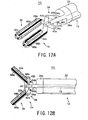
- This crossing structure allows the gripping surfaces 38a and 38b to be located face to face when the gripper 32 is closed as shown in Fig. 3A (hereinafter, the jaw positions shown in Fig. 3A are referred to as “closed,” in contrast, jaw positions shown in Fig. 3B are referred to as “open.”)
- the jaws 32a and 32b function as gripping members which are able to grip a portion of tissue of a patient and function as electrodes to make high frequency current pass through the gripped tissue.
- a side of each of the jaws 32a and 32b is formed to provide the gripping surface 38a (38b) which is made to touch the tissue to be gripped.
- Each of the gripping surfaces 38a and 38b has irregularities to enhance a gripping force.
- the side-view shapes of the irregularities are for example triangular as shown in Figs. 3A and 3B , but this is not a decisive shape. Any shapes, such as round shapes and quadrangular shapes, can be applied too the irregularities.
- the surface, including the gripping surface 38a (38b), of each jaw 32a (32b) is entirely subjected to thin coating of, for example, a fluorocarbon resin for preventing the tissue from being burned dry to the jaws 32a and 32b.
- the outer surfaces of the joints 32c and 32d of the gripper 32 are formed into insulative surfaces. That is, the joints 32c and 32d, which compose bases of the respective jaws 32a and 32b, are coated with insulative material, so that an electric short circuit between the joints 32c and 32d touched to each other is surely prevented.
- the insulative outer surfaces of the joints 32c and 32d can be formed by covering the entire joints 32c and 32d with an electrical insulative sheet or can be coated with insulative material.
- the joints 32c and 32d which compose the bases of the pair of jaws 32a and 32b, are crossed to each other and rotatably held by a pin 40 bridging the tips of the arms 36b of the tip securing member 36.
- the pair of jaws 32a and 32b can be opened and closed mutually as shown by arrows AR in Figs. 3B (opened position) and 3A (closed position) around the pin 40 serving as a fulcrum at the tips of the arms 36b.
- the pin 40 is coated with insulative material such as fluorocarbon resin.
- a distance (width) ⁇ between the outer surfaces of the jaws 32a and 32b measured when the pair of jaws 32a and 32b is closed (at the mutually nearest positions) is 1.5 to 6 mm in the present embodiment. Especially it is preferable that the distance ⁇ is 2 to 3.5 mm.
- This distance ⁇ is set to establish both the insertion performance into the endoscope's insertion channel 102 and an appropriate region for blood stanching.
- the axial length of each of the jaws 32a and 32b is in a range of 1 to 20 mm, and particularly, the axial length of 4 to 12 mm is preferable. This length is also determined to have both the insertion performance into the endoscope's insertion channel 102 and an appropriate region for blood stanching.
- the link member 14 is provided with a first and second links 34a and 34b.
- One end of the first link 34a is rotatably coupled with the base of the joint 32c for one of the jaws, 32a, with the aid of a first rotatably support pin 42a.
- one end of the second link 34b is rotatably coupled with the base of the joint 32d for the other of the jaws, 32b, with the aid of a second rotatably support pin 42b.
- the other ends of both first and second links 34a and 34b are rotatably held by a third rotatably support pin 42c at the tip of the wire 18.
- the pair of links 34a and 34b are arranged to rotatably connect to the tip of the wire 18 the help of the third rotatably support pin 42c.
- the first and second links 34a and 34b ban be rotated around the third rotatably support pin 42c.
- the rotations of the links 34a an 34b make it possible that the bases of the jaws 32a and 32b rotate around the first and second rotatably support pins 42a and 42b, respectively.
- the jaws 32and 32b can therefore be rotated around the pin 40 in the mutually opposite directions as shown by arrows AR in Fig. 3B .
- first and second links 34a and 34b are also coated with insulative material such as fluorocarbon resin, respectively, so that an electrical short-circuit between the links 34a and 34b can be prevented.
- the third rotatably support pin 42c is also subjected to insulative coating with material such as fluorocarbon resin. Thus an electrical separation between the third rotatbly support pin 42c and the arms 36b are secured, with no conductive linkage therebetween.
- the links 34a and 34b have stoppers 34c and 34d to restrict angular rotation amounts of the jaws 32a and 32b, respectively.
- Each of the stoppers 34c and 34d is disposed on each of sides of the links 34a and 34b to protrude therefrom.
- the stoppers 34c and 34d are located in such a manner that, when the wire 18 is pulled by an operator to establish a gap (spacing) of predetermined distance ⁇ between the jaws 32a and 32b, the stoppers 34a and 34b just come into contact with the arms 36b, respectively.
- the stoppers 34c and 34d may have any outer shapes, not limited to a cylindrical shape as depicted in Figs. 3A and 3B . Any outer shapes including a triangle and a square may be available for the stoppers 34c and 34d.
- the distance ⁇ is preferably a value ranging from 0.1 mm to 2 mm.
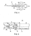
- the handle 16 is provided with an operating main body 62 and a slider 64.
- the operating main body 62 includes a shaft-like sliding guide 62a and a finger-hooked ring 62b disposed at the base of the sliding guide 62a.
- the slider 64 which is slidable along the sliding guide 62a, comprises first and second current-conducting connectors 64a and 64b.
- the slider 64 further comprises finger-hooked rings 64c and 64d with which the index and middle fingers are hooked.
- the wire 18 is inserted in the sheath 22 of the insertion member 12 to extend therealong and the base of the wire 18 is connected to the first and second current-conducting connectors 64a and 64b disposed on the slider 64, respectively.
- the connectors 64a and 64b each are coupled with cables coming from a high frequency cautery power supply unit (not shown). This power supply unit is switched on/off by, for example, operating a foot switch coupled thereto and configured to generate high frequency voltage.
- the slider 64 is moved to slide along the sliding guide 62a, which makes the wire 18 to slide backward and forward. Those slide movements cause the jaws 32a and 32b at the tip of the treatment member 14 to open and close, line shown in Figs. 3A and 3B .
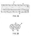
- the wire 18 comprises an insulative coating member 52 of high insulation performance, which is made from fluorocarbon resin or polyolefin, and a pair of conductive wires 54a and 54b mutually insulated by the coating member 52. It is also possible to have the two conductive wires 54a and 54b inserted into insulative tubes with two or more lumens. Alternatively, the two conductive wires 54a and 54b may be covered by insulative coats, respectively. Still, the conductive wires 54a and 54b may not be confined to the forgoing structure in which the two wires are combined into one cable shown in Fig. 2B , but the wires 54 and 54b may be separated as independent cables.
- the first conductive one 54a has a tip coupled with the first link 34a by the third rotatably support pin 42c (refer to Fig. 3A ).
- the base of the first conductive wire 54a is coupled with the first current-conducting connector 64a.
- the second conductive wire 54b has tip linked with the second link 34b by the third rotatably support pin 42c.
- the base of the second conductive wire 54b is connected with the second current-conducting connector 64b.
- the third rotatably support pin 42c is connected with the wire 18 and both the first and second conductive wires 54a and 54b, in which the conductive wires 54a and 54b are electrically separated from each other.
- the third rotatably support pin 42c is formed of a pair of conductive members between which an insulator is placed. Precisely, the pin 42c is formed into a bar consisting of a pair of conducting portions and an insulator bridging both conducting portions.
- To the conducting portions are connected with the forgoing first and second conductive wires 54a and 54b.
- One pair of conducive portions of the pin 42c has linkages with the first and second links 34a and 34b, respectively.
- all of the first current-conducting connector 64a, the first conductive wire 54a of the wire 18, the third rotatably support pin 42c, the first link 34a, the first rotatably support pin 42a, and the first jaw 32a are not only eclectically connected but also mechanically coupled with each other.
- all of the second current-conducting connector 64b, the second conductive wire 54b of the wire 18, the third rotatably support pin 42c, the second link 34b, the second rotatably support pin 42b, and the second jaw 32b are not only eclectically connected but also mechanically coupled with each other.
- one ends of not-shown cables are connected respectively to the first and second current-conducting connectors 64a and 64b of the bipolar forceps 10.
- the other end of each of the cables is connected with the high frequency coutery power supply unit not shown, thus establishing the connections between the bipolar forceps 10 and the high frequency coutery power supply unit.
- both tips of the first and second links 34a and 34b are pulled back, which will cause both the links 34a and 34b to rotate about the third rotatably support pin 42c.
- the rotation of the links 34a and 34b involves pulling of the first and second rotatably support pins 42a and 42b backward, so that the pair of joints 32c and 32d is rotated bout the pin 40. This will cause the pair of jaws 32a and 32b to approach to each other, that is, to close, as shown in Fig. 3A .
- the insertion member 12 thereof is inserted into the insertion channel 102 of the endoscope 100, as shown in Fig. 1 , so that the insertion member 12 is inserted into the body of a patient. Then the endoscope 100 is operated to guide the treatment member 14 at the tip of the insertion member 12 to a spatial position near a tissue to be treated in the body.
- the slider 64 of the handle 16 is operated by an operator to slide forward along the sliding guide 62a. This operation allows the wire 18 to advance, which will give the operations to the jaws, which are opposite to the above. In other words, the link member 34 is forced to drive the jaws 32a and 32b to separate from each other, resulting in the open position of the jaws, as shown in Fig. 3B .
- the jaws 32a and 32b which are in their open attitude, are moved to bite at a portion of the tissue 110 to be treated, with the tissue 110 between the jaws 32a and 32b.
- the slider 64 is then operated to close jaws 32a and 32b. That is, as shown in Fig. 5 , the tissue 110 to be treated is gripped by the jaws 32a and 32b, with the gripping surfaces 38a and 38b facing the tissue 110 respectively.
- the not-shown foot switch connected to the high frequency cautery power supply unit is operated to apply high frequency voltage to the first and second current-conducting connectors 64a and 64b through cables.
- the voltage is therefore supplied to the jaw 32a via the connector 64a, the first conductive wire 54a of the wire 18, the third rotatably support pin 42c, the first link 34a, and the first rotatably support pin 42a.
- the voltage is supplied to the jaw 32b via the connector 64a, the first conductive wire 54b of the wire 18, the third rotatably support pin 42c, the second link 34b, and the second rotatably support pin 42b.
- the jaws 32a and 32b are prevented from being short-circuited when the high frequency current is supplied to the jaws 32a and 32b, because there is formed a gap ⁇ between the gripping surfaces 38a and 38b and the outer surfaces of the joints 32c and 32d are kept insulative.
- the minimum gap ⁇ between the gripping surfaces 38a and 38b is secured by touching the arm 36b of the tip securing member 36 to the stoppers 34c and 34d.
- the stoppers 34c and 34d limit the slider 64 from moving backward any more, even if the operator wants. Additionally, because there is no insulative portion on the gripping surfaces 38a and 38b of the jaws 32a and 32b, there is no need for worrying about positions on the clipping surfaces 38a and 38b at which the tissue 110 is gripped.
- the tissue 110 can also be cut open by supplying the high frequency current to the jaws 32a and 32b, as shown in Fig. 6 .
- the electrical short circuit resulting from clagged mucosa of the tissue to the jaws 32a and 32b can be prevented between the jaws 32a and 32b.
- a blood stanching operation it is sometimes desired to simply apply a blood stanching operation to tissue 110, without gripping it.
- the front surfaces of the respective jaws 32a and 32b are made to press onto a treatment-desired portion of the tissue 110.
- the jaws 32a and 32b receives high frequency current supply as stated above, whereby the desired portion of the tissue 110 coagulates simply for stop bleeding due heat caused by the current.
- This operation also enjoys the benefit of the minimum gap gamma formed between the jaws 32a and 32b. That is, the gap gamma prevents the jaws 32a and 32b from being short-circuited with each other, while still making the high frequency current pass through the tissue 110. In this way, the tissue 110 can undergo the coagulating treatment for stop blooding in a simple manner.
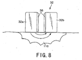
- An alternative stop bleeding operation is to make flat side surfaces of the respective jaws 32a and 32b press onto a desired portion of tissue 110, as shown in Fig. 8 .
- the high frequency current is supplied to the jaws 32a and 32b by applying the high frequency voltage, resulting in coagulating the pressed portion of the tissue 110 for blood stanching.
- the short circuit between the jaws 32a and 32b is prevented well due to the minimum gap gamma between the jaws 32a and 32b and the insulative outer surfaces of the joints 32c and 32d, whilst the current flow through the tissue 110 is secured.
- the tissue 110 can be coagulated at its desired portion, for stop bleeding in a simple but steady manner.
- the present embodiment can provide various advantages.
- the predetermined-length gap ⁇ is formed between the jaws 32a and 32b and the joins 32c and 32d have the insulative outer surfaces. These structures prevent the short circuit between the jaws 32a and 32b when the jaws 32a and 32b are closed to each other.
- the bipolar forceps 10 with the openable/closable gripper 32 which has the capability of gripping a desired portion of the tissue and being pressed onto (made to touch) a desired portion of the tissue without paying attention to pressing portions of the gripper 32.
- various types of high frequency medial treatments can be done in an easier manner.
- FIGs. 9A and 9B a second embodiment of the high frequency treatment device according to the present invention will now be described. Incidentally, for the sake of simplified explanations, the similar or identical parts in the present and subsequent embodiments to those in the first embodiment will have the same reference numerals.
- the second embodiment corresponds to a modification of the bipolar forces 10 explained in the first embodiment.
- the bipolar forceps 10 according to the present embodiment has a link mechanism 34 different in structures from that explained in the first embodiment.
- the tip of the wire 18 is divided into two so as to connect to first and second branch wires 18a and 18b which are conductive.
- the first branch wire 18a is connected to the first conducive wire 54a (refer to Fig. 2A ), whereas the second branch wire 18b is connected to the second conductive wire 54b.
- the tips of the first and second wires 18a and 18b are coupled respectively with the joints 32c and 32d functioning as the bases of the jaws 32a and 32b so as to allow the joints 32c and 32d to rotate around the pin 40.
- the wires 18a and 18b have outer surfaces on each of which an insulative layer is coated.
- First and second stoppers 18c and 18d are fixed at axial predetermined positions of the first and second branch wires 18a and 18b, respectively. The positions are decided appropriately to touch a blocker 22a formed on the inner wall surface of the sheath 22, when the wire 18 is pulled back.
- the blocker 22 is positioned at an axial predetermined position of the sheath 22 and formed into a cylinder having a bore through which the two branch wires 18a and 18b are placed movably in the axial direction of the insertion member 12.
- the shapes of the first and second stoppers 18c and 18d and the blocker 22a are not limited to those shown in Figs. 9A and 9B . Any shapes can be used as long as the equivalent functions are achieved.
- the positional relationship of the first and second stoppers 18c and 18d and the blocker 22a is designed such that the first and second stoppers 18c and 18d are just made to touch the blocker 22a, when the distance (spacing) between the gripping surfaces 38a and 38b of the jaws 32a and 32b is reduced down to a predetermined minimum length ⁇ in response to pulling the wire 18 backward.
- the minimum gap length ⁇ is therefore secured between the jaws 32a and 32b of the treatment member 14.
- both the length of the wire 18 and the sliding guide 62a of the operating main body 62 can be adjusted so that, when the predetermined length ⁇ is established between the gripping surfaces 38a and 38b of the jaws 32a and 32b, the slider 64 is located nearest to the operating main body 62 so as not to permit the move of the slider 64 backward any more.
- the handle 16 shown in Fig. 4 is operated by an operator so that the wire 18 is moved forward and backward along the sheath 22 of the insertion member 12. This operations are converted into forward and backward movements of the first and second branch wires 18a and 18b, which are then transmitted to the joints 32cand 32d.
- the jaws 32a and 32b are then operated around the pin 40 so that the jaws 32a and 32b get separated from each other or closer with each other (i.e., open and close).
- an operator's forward operation of the wire 18 enables the jaws 32a and 32b to open, while an operator's backward operation of the wire 18 results in the close of the jaws 32a and 32b.
- this closing operation the distance between the gripping surfaces 38a and 38b is gradually reduced, and finally becomes the predetermined value ⁇ just when the first and second stoppers 18c and 18d are made to touch the block 22a for a stop thereat.
- the wire 18 cannot be pulled backward any more, with the result that the minimum distance ⁇ between the gripping surfaces 38a and 38b can be kept.
- the bipolar forceps 10 according to the present embodiment can enjoy the identical advantages to those explained in the first embodiment. Additionally, the choice in design can be expanded.
- FIG. 10A and 10B to 13 a third embodiment of the present embodiment will now be described.
- This embodiment relates to another structure of the jaws.
- a gripper 32 shown in Figs. 10A and 10B has a pair of jaws 32a and 32b, which are made from an eclectically insulative material, such as ceramics, of high heat resistance. That is, in the present embodiment, the jaws 32a and 32b cannot be used as electrodes by themselves.
- first and second electrode members 68a and 68b each made from conductive materials are arranged on each of the outer surfaces of the jaws 32a and 32b such that the electrode members are located to have a predetermined distance separation therebetween. That is, the two electrode members 68a and 68b, which are charged with positive and negative polarities, are arranged around each of the jaws 32a and 32b in a spiral and positive/negative-alternate fashion. Both of the electrode members 68a and 68b are eclectically connected with the first and second current-conducting connectors 64 and 64b via the link mechanism 34 and the wire 18, respectively.
- the operations of the bipolar forceps 10 will now be described.
- the operations involving opening and closing the jaws 32a and 32b and the operations involving the closed state of the jaws 32a and 32b are similar to those explained in the first embodiment, thus omitting their detailed explanations. Since the jaws 32a and 32b have the first and second electrode members 68a and 68b spirally disposed on the outer surface of the jaws 32a and 32b along the entire axial range thereof, the jaws 32 and 32b provide the similar operations to those explained in the first embodiment.
- one jaw 32b is made to touch a desired portion of tissue 110 and high frequency vulgate is applied to the first and second electrode members 68a and 68b in the same manner as the foregoing.
- portions of the tissue 110 which along the jaw 32b and each of which resides between the first and second electrode members 68a and 68b, are subjected to high frequency current flow, as shown by arrows in Fig. 11 , thus leading to coagulation for blood stanching. That is, only one jaw 32b can be used for blood stanching by simply pressing the jaw 32b to a desired treatment portion of the tissue 110 and applying the high frequency voltage to the jaws 32a and 32b. This is also true of the other jaw 32a.
- spiral electrode members 68a and 68b on each of the jaws 32a and 32b as shown in Figs. 10A and 10B are not always necessary.
- An alternative is for example parallel-disposed electrode members 68a and 68b on each of the jaws 32a and 32b as shown in Figs. 12A and 12B .
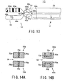
- FIG. 13 Another electrode structure can by shown by Fig. 13 , in which the first and second electrode members 68a and 68b are disposed on only one 32a of the jaws 32a and 32b, not absolutely necessary for arranging the electrodes on both the jaws 32a and 32b. This type of jaws 32a and 32b are still able to use for both the gripping operations and the touching operations.
- Fig. 14A shows a front view of jaws 32a and 32b of a gripper 32 used by a bipolar forceps 10 according to the present embodiment.
- each of the jaws 32a and 32b has first and second electrode members 70a and 70c which are formed into rectangular prisms, respectively, and a plate-like insulator 70c rigidly sandwiched between the electrode members 70a and 70c.
- one of the jaws, 32a is composed of the first electrode member 70a, insulator 70c, and second electrode member 70c arranged in this order from the left in Fig. 14A .
- the second electrode member 70b, insulator 70c, and first electrode member 70a are aligned to form the other jaw 32b.
- the first and second electrode members 70a and 70b receive the high frequency current from positive and negative polarity terminals of the power supply unit, respectively.
- sides of the pair of jaws 32a and 32b can be pressed onto a bleeding portion of tissue 110.
- the high frequency voltage is applied to the second electrode member 70b of one of the jaws, 32a, and the first electrode member 70a of the other jaws 32b, resulting in that the portion of the tissue 110 touching both the electrode members 70b and 70a undergo the supply of high frequency current, as indicated by an arrow in Fig. 15A .
- the tissue portion between the pair of jaws 32a and 32b is coagulated to stop bleeding. This operation is also true of the jaws 32a and 32b which have gripped a portion of the tissue 110 for treatment.
- FIG. 15B A further use of the gripper 32 is depicted as shown in Fig. 15B , in which only one of the jaws 32a and 32b is used for treatment. For example, a side of one of the jaws, 32b, is pressed onto a bleeding portion of tissue 110. In this state, the first and second electrode members 70a and 70b on the jaw 32b receives an application of high frequency voltage so that high frequency current passes through a portion residing between the electrode members 70a and 70b. Accordingly, the portion between the electrode members 70a and 70b is coagulated for blood stanching.
- each of the jaws 32a and 32b has a U-shaped (in section) insulator 70c.
- one of the jaws, 32a is composed of a rectangular-prism-like first electrode member 70a, the U-shaped insulator 70c placed to embrace the first electrode member 70a, and a second electrode member 70b U-shaped in section and placed to embrace the insulator 70c, which are all combined rigidly.
- the other jaw 32b is also composed of the second electrode member 70b, the insulator 70c, and the first electrode member 70a and combined with each other in the same manner as the jaw 32a.
- side surfaces of the paired jaws 32a and 32b can be pressed onto a bleeding portion of tissue 110. This allows the tissue portion existing between the first electrode member 70a of one of the jaws, 32a, and the second electrode member 70b of the other jaw 32b to receive the flow of high frequency current. This operation is applicable to the pair of jaws 32a and 32b which has gripped a portion of the tissue 110 for high frequency treatment.
- only one of the jaws for example, 32b, can be used for high frequency treatment such as blood stanching. That is, it is enough that one of the side of the jaw 32b, which is opposed to the remaining jaw 32a, is pressed onto a bleeding portion. In this case, a portion residing between the first and second electrode members 70a and 70b undergoes the flow of high frequency current, thus providing the stanching operation at the pressed portion. This is also true of the other jaw 32a.
- a further variation is to arrange the electrode members 70a and 70b in only one of the jaws 32a and 32b, not always necessary for arranging them on both the jaws 32a and 32b. Still, in each or only one of the jaws 32a and 32b, a plurality of sets of positive- and negative-polarities electrode members may be formed. This structure of plural sets of electrodes can be achieved by employing two or more insulators arranged in the same manner as the above.
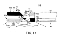
- a bipolar forceps 10 has a tubular tip securing member 36 with a tubular member 36a, which is similar to that explained before and located at the base of the treatment member 14.
- first and second electrode members 72a and 72b On the outer surface of the tubular member 36a, formed in the circumferential direction are first and second electrode members 72a and 72b and an insulator 72c separating the electrode members 72a and 72b from one the other. That is, the insulator 72c of a predetermined width prevents the electrode members 72a and 72b from being short-circuited.
- the first electrode member 72a of for example positive polarity is also disposed entirely on the outer surface of one of the jaws, 32a, whilst the second electrode member 72b of negative polarity is also disposed entirely on the outer surface of the jaw 32b.
- both jaws 32a and 32b function as a pair of electrodes, like the jaws 32a and 32b in the first embodiment.
- the first electrode member 72a on the tubular member 36a and the second electrode member 72b on the other jaw 32b are paired in that they are positionally biased on the same side in a direction perpendicular to the central axis of the insertion member 12.
- the second electrode member 72b on the tubular member 36a and the first electrode member 72a on the other jaw 32b are paired.
- the first and second electrode members 72a and 72b are electrically connected to the first and second current-conducting connectors 64a and 64b, respectively, within the sheath 22 of the insertion member 12 via the wire 18.
- the paired first electrode member 72a on the tubular member 36a is pressed together onto the portion.
- An application of high frequency voltage to the first and second electrode members 72a and 72b thus pressed allows high frequency current to flow between the jaw 32b (second electrode member 72b) and the first electrode member 72a on the tubular member 36a, as depicted by an arrow in Fig. 17 . This will cause coagulation at the desired portion for blood stanching.
- the present embodiment provides an advantage, in addition to those gained in the first embodiment. That is, in pressing the jaws 32a and 42b for blood stanching, either of the positionally biased two pairs selected from the jaws 32a and 32b and the electrodes 72 and 72b is simply pressed onto a bleeding portion of tissue 110. An example is shown in Fig. 17 . In such a pressed state, the electrode members 72a and 72b is subject to the supply of high frequency current. This is a simple operation for blood stanching, shortening a time for the overall treatment operations.
- first and second electrodes 72 and 72b are not limited to that shown in Fig. 17 .
- first electrode member 72a and the second electrode member 72b are not limited to one in number, respectively.
- Plural mutually-opposite-polarity electrodes can be placed on the jaw 32a (32b) at intervals, for example.
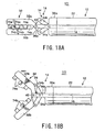
- Figs. 18A and 18B show a gripper of a bipolar forceps 10 according to the present embodiment, in which the gripper 32 comprises a pair of jaws 32a and 32b made from conductive materials, like the first embodiment.
- the jaws 32a and 32b function as electrodes by themselves.
- the jaws 32a and 32b are electrically connected to the first and second current-conducting connectors 64a and 64b via the wire 18.
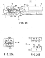
- a plurality of insulators 74a are rigidly built at intervals along the longitudinal (axial) direction of the gripper 32.
- Each of the insulators 74a and 75b is formed into, for example, a cubic or a cuboid in the present embodiment, but this is not a decisive list. Any shapes such as hemisphere shape, truncated cone shape, and triangular pyramid shape can be adopted as the insulators 74a and 74b.
- the number of insulators 74a (74b) is one to five in number in the axial direction of each jaw in order to keep a sufficient gripping force.
- the insulators 74a and 74b are made from a highly insulative and heat-resistive material, for example, selected from a group consisting of ceramic material, cycloolefin resin, norbornane resin, polyether ether ketone, polyimide, polyamide, and polysufone.
- the dimensional configurations are given to the jaws 32a and 32b such that, when the jaws 32a and 32b are closed at full, the insulators 74a and 74b on the mutually opposed gripping surfaces 38a and 38b do not interfere with each other.
- the insulators 74a and 75b are located alternately along the longitudinal direction of the gripper 32 when the closing operations of the jaws 32a and 32b are completed and a gap of slight distance is formed between the mutually adjacent insulators 74a and 74b on both the jaws 32a and 32b in the longitudinal direction.
- the portion of the tissue 110 is gripped between the gripping surfaces 38a and 38b.
- the tissue portion 10 is pressed onto the gripping surface 38b of one of the jaws, 32b, by the insulators 74a of the other jaw 32a and pressed onto the gripping surface 38a of the jaw 32a by the insulators 74b on the jaw 32b.
- high frequency voltage flows through the gripped tissue portion, as shown by arrows in Fig. 19 .
- the gripped tissue portion 110 coagulates to stop bleeding therefrom.
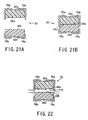
- FIGs. 20A and 20B which pictorially depict front views of the jaws 32a and 32b composing the gripper 32.
- a plurality of rows of the insulators 74a (74b) are arranged in parallel in the longitudinal (axial) direction of the gripper 32, not limited to the arrangement in which each row of the insulators 74a (74b) is aligned in the direction perpendicular to the longitudinal direction.
- the axial length of each insulator 74a (74b) is 0.5 to 20 mm and set to an amount not to protrude from the jaws 32a and 32b.
- a seventh embodiment of the present invention will now be described.
- This embodiment provides a modified example from the electrode configurations shown in the sixth embodiment in which the stoppers 34c and 34d explained in Figs. 3A and 3B are unnecessary.
- a bipolar forceps 10 has a gripper 32 shown in Figs. 21A and 21B .
- the gripper 32 has jaws 32a and 32b made from insulative materials. Gripping surfaces 38a and 38b formed on the jaws 32a and 32b can be contacted to each other, as shown in Fig. 21B .
- first and second L-shaped electrode members 76a and 76b are secured with a predetermined interval therebetween.
- the first and second L-shaped electrode members 76a and 76b are secured to cover part of the upper surface and a side surface and to protrude from the lower end of the jaw 32a by a predetermined length, respectively, as shown in Fig. 21A .
- the two electrode members 76a and 76b are separated from each other by a predetermined length.
- the first and second L-shaped electrode members 76a and 76b are secured to cover part of the lower surface and part of a side surface of the jaw 32b, respectively, as shown in Fig. 21A .
- the two electrode members 76a and 76b are separated a predetermined length from each other.
- the electrode members 76a and 76b receive an application of high frequency voltage of positive and negative polarities, respectively.
- the first and second electrode members 76a and 76b can be formed into any shapes, not limited to those expressed by Figs. 21A and 21B . Though an arbitrary number of electrode members are available for each of the first and second electrode members 76a and 76b, it is preferable to dispose two to six electrode members are disposed along the longitudinal direction of the jaws 32a and 32b when taking the arrangement areas on the jaws into account.
- the pair of jaws 32a and 32b can also grip a portion of tissue 110 to stop bleeding from the portion.
- This gripping operation is illustrated in Fig. 22 .
- high frequency voltage is applied to the first and second electrode members 76a and 76b on each of the jaws 32a and 32b so that high frequency current flows between the jaws 32a and 32b through the portion of the tissue. Hence the gripped portion is coagulated to stop bleeding.
- one-side surfaces of the jaws 32a and 32b can be touched to the tissue 110 to apply high frequency voltage to the first and second electrode members 76a and 76b.
- high frequency current flows between the paired first and second electrode members 76a and 76b on the paired jaws 32a and 32b, with a touched tissue portion coagulated for blood stanching.
- a high frequency treatment device when it is used, is inserted into the insertion channel 102 of for example the endoscope 100 as shown in Fig. 1 .
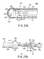
- a high frequency treatment device 200 according to the present embodiment is provided with a monopolar stanching device (a coagulating device or a coagulater) 210 and a bipolar forceps (high frequency gripping forceps) 10 placed within the monopolar stanching device 210.
- the bipolar forceps 10 by be, by way of example, identical in configurations to those explained in the first to seventh embodiments. Particularly in the present embodiment, the bipolar forceps 10 is identical to that in the first embodiment.
- the monopolar stanching device 210 is provided with a thin and flexible insertion member 212, a treatment member 214 secured to the tip of the insertion member 212, and a current-supply connector 216 secured to the base of the insertion member 212.
- the insertion member 212 is provided with a sheath 222 rotatable against the treatment member 214.
- the sheath 222 is made from a resin material that exhibits an excellent flexibility.
- the sheath 222 may however be formed from a metal-made flexible coil, not limited to the resin materials.
- the sheath 222 has an inner diameter to form an inner tubular space through which the treatment member 12 and insertion member 14 of the bipolar forceps 10 are inserted smoothly.
- the outer diameter of the sheath 222 is 1.5 to 6 mm. Particularly it is preferable if the outer diameter is 2.2 - 3.5 mm.
- a current-supply cable 218 is arranged along the axial direction of the sheath 222.
- the current-supply connector 216 of the monopolar stanching device 210 is a tubular connecter body 262 and a terminal 264 secured on this connector body 262.
- the connector body 262 has an inner hole connecting both axial ends and the diameter of the hole is set to an amount permitting the treatment member 14 and insertion member 12 of the bipolar forceps 10 to be inserted smoothly.
- the terminal 264 is electrically connected with an end of the current-supply cable 218.
- the treatment member 214 is provided with a hemispheric valve 226 that has sufficient elasticity and an electrode 228 being formed from conductive material, such as elastomeric resin, and covering the valve 226.
- a hemispheric valve 226 that has sufficient elasticity and an electrode 228 being formed from conductive material, such as elastomeric resin, and covering the valve 226.
- Each of the valve 226 and the electrode 228 is divided by slits 230 into plural segments and formed to open and close.
- each segment of the electrode 228, which is the same in shape as each segment of the valve 226, is affixed.
- the tip of the current-supply cable 218 is electrically coupled with the electrode 228. That is, the current-supply cable 218 electrically connects the electrode 228 and the terminal 264 of the current-supply connector 216.
- the segments of the electrode 228 are affixed on all the segments of the valve 226, but is enough if only one electrode segment is affixed on any segment of the valve 226.
- the number of slits 230 of the valve 226, that is, the number of segments thereof, is arbitrary.
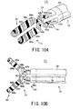
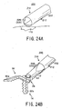
- the high frequency treatment device 200 is inserted into the insertion channel of the endoscope 100 so as to make the tip of the device 200 approach a portion of tissue 110 to be treated, in which the treatment member 14 and insertion member 12 of the bipolar forceps 10 are inserted into the insertion member 212 (sheath 222) of the monopolar stanching device 210 through the tip thereof. As shown in Fig. 24A , the tip of the high frequency treatment device 200 is served by the treatment member 214 of the monopolar stanching device 210.
- the bipolar forceps 10 is operated to advance toward the tip of the monopolar stanching device 210 within this device 210. Then, as shown in Fig. 24B , from the tip of the monopolar stanching device 210, the treatment device 14 of the bipolar forceps 10 is pushed out to open the valve 226 and electrode 228 of the outer device 210. In this pushing operation, since the valve 226 has elasticity, the segments of the valve 226 can be pushed aside to form an opening in an easy manner. Thus the treatment member 14 of the bipolar forceps 10 can protrude from the outer device 210.
- the treatment member 14 is able to grip a portion of tissue 110 for blood stanching using the current-supplied jaws 32a and 32b.
- the monopolar stanching device 210 can be used for blood stanching by having the device 210 itself pressed onto a portion of tissue.
- the high frequency treatment device 200 in which the bipolar forceps 10 is contained within the monopolar stanching device 210, is operated so that its tip approaches a bleeding portion of tissue 110, as shown in Fig. 24A . And the electrode 228 on the tip of the monopolar stanching device 210 is touched to the bleeding portion and receives an application of high frequency voltage from the high frequency power supply unit. This application allows high frequency current to flow through the electrode and bleeding portion, with the blooding portion coagulated for performing blood stanching.
- a variation according to this embodiment is to replace the bipolar forceps 10 with a monopolar forceps and to replace the monopolar stanching device 210 with a bipolar stanching device.
- FIG. 25 and 26 a ninth embodiment of the present invention will now be described, which is modified from the constructions in the eighth embodiment.
- a high frequency treatment device 200 has also a double-device structure and is provided with a bipolar forceps 10' arranged as an outer device and a monopolar stanching device 210' arranged within an insertion member 12' of the bipolar forceps 10'.
- the insertion member 12' of the forceps 10' has a tubular through-hole sufficient therein for insertion of an insertion member 212' of the monopolar stanching device 210'.
- the bipolar forceps 10' has a handle 16' with an operating main body 62', which is similar to the ones of the foregoing embodiments.
- an insertion channel 216a is formed to accept the insertion of a treatment member 214' and an insertion member 212' of the monopolar stanching device 210'.
- This insertion channel 216a has a diameter of which amount is appropriate for a smooth insertion of the insertion member 212'.
- This high frequency treatment device 200 will now be explained in terms of its operations.
- the bipolar forceps 10' functioning as part of the device 200, has the capability of stopping bleeding. Cables are used to connect both the monopolar stanching device 210' and the bipolar forceps 10' to the high frequency power supply unit.
- the high frequency treatment device 200 that is, the bipolar forceps 10', is operated to make its tip approach a bleeding portion of tissue through the insertion channel 102 of the endoscope 100.
- jaws 32a' and 32b' of the bipolar forceps 10' are then driven to grip the bleeding portion and subjected to high frequency current supply.
- the device 200 is operated to make its tip approach a bleeding portion of tissue. Then a gripper 32' of the bipolar forceps 10', which consists of the jaws 32a' and 32b', is opened by driving the jaws 32a' and 32b' so that its tips are rotated in the mutually different directions. After completing this open as shown in Fig. 25 , the monopolar stanching device 210' is moved to protrude its treatment member 214' from the tip of the insertion member 12' of the outer forceps 10'.
- An electrode 228' on the tip of the monopolar stanching 210' is then pressed to a bleeding portion of tissue.
- the blood stanching is achieved at the portion, like the foregoing.
- the gripper 32' of the bipolar forceps 10' can grip tissue to perform blood stanching with the aid of high frequency current. Further, any portion of the treatment member 214' of the monopolar stanching device 210' can be pressed to a bleeding portion of tissue for stanching.
- both of these stanching ways can be used selectively depending on various bleeding conditions. That is, the single high frequency treatment device 200 has the two high frequency treatment functions, thus being convenient and efficient for the stanching operations.
Landscapes
- Health & Medical Sciences (AREA)
- Surgery (AREA)
- Engineering & Computer Science (AREA)
- Life Sciences & Earth Sciences (AREA)
- Biomedical Technology (AREA)
- Otolaryngology (AREA)
- Nuclear Medicine, Radiotherapy & Molecular Imaging (AREA)
- Plasma & Fusion (AREA)
- Physics & Mathematics (AREA)
- Heart & Thoracic Surgery (AREA)
- Medical Informatics (AREA)
- Molecular Biology (AREA)
- Animal Behavior & Ethology (AREA)
- General Health & Medical Sciences (AREA)
- Public Health (AREA)
- Veterinary Medicine (AREA)
- Surgical Instruments (AREA)
Claims (26)
- Hochfrequenz-Behandlungsgerät, das umfasst:ein Einführelement (12);ein Klemmbackenpaar (32a, 32b), das eine Längsrichtung bereitstellt, entlang derer jede der Klemmbacken langgestreckt ausgebildet ist, wobei jede Klemmbacke eine Außenfläche hat, an der eine elektrische Elektrode ausgebildet ist, wobei die Elektrode den gesamten Bereich der Außenfläche in der Längsrichtung einnimmt, wobei die Außenfläche eine Greiffläche umfasst, die dazu eingerichtet ist, einen Gewebeabschnitt eines Objekts zu greifen;ein Verbindungselement (34, 42), das dazu eingerichtet ist, i) das Klemmbackenpaar zu halten, um in einer Richtung geöffnet und geschlossen zu werden, in der sich die Greifflächen der Klemmbacken selektiv aneinander annähern oder voneinander entfernen, und ii) das Klemmbackenpaar mit einer Spitze des Einführelements (12) zu verbinden, wobei ein elektrisch isolierendes Material auf eine Außenfläche des Verbindungselements (34, 42) aufgebracht ist;ein Kontaktverhinderungselement (34a, 34b; 18a, 18b, 18c, 18d; 74a, 74b), das dazu eingerichtet ist, einen mechanischen Kontakt zwischen den Greifflächen des Klemmbackenpaars (32a, 32b) zu verhindern, wenn sich die Klemmbacken aneinander annähern;eine Energieleitung (64a, 18(54a), 42c, 34a, 42a, 64b, 18(54b), 42c, 34b, 42b) die durch das Einführelement (12) verläuft und dazu eingerichtet ist, über das Verbindungselement (34, 42) eine Hochfrequenzspannung an die Klemmbacken (32a, 32b) anzulegen, um zu veranlassen, dass ein Hochfrequenzstrom durch die Klemmbacken (32a, 32b) fließt; undeinen Betätigungsdraht (18), der durch das Einführelement (12) verläuft und dazu eingerichtet ist, über das Verbindungselement (34, 42) Öffnungs- und Schließbewegungen an die Klemmbacken (32a, 32b) zu übertragen.
- Gerät nach Anspruch 1, bei dem das Kontaktverhinderungselement in dem Verbindungselement (34, 42) oder dem Einführelement (12) ausgebildet ist.
- Gerät nach Anspruch 2, bei dem jede Klemmbacke der paarweise vorgesehenen Klemmbacken (32a, 32b) aus einem leitfähigen Material besteht, um als Elektrode zu dienen.
- Gerät nach Anspruch 3, bei dem jede Klemmbacke der paarweise vorgesehenen Klemmbacken (32a, 32b) als positive oder negative Elektrode dient, an die die Hochfrequenzspannung angelegt ist.
- Gerät nach Anspruch 4, bei dem das Kontaktverhinderungselement mit einem Begrenzungselement versehen ist, um einen Rotationsbereich einer jeden Klemmbacke der paarweise vorgesehenen Klemmbacken (32a, 32b) in einer Schließrichtung zu begrenzen, entlang derer jede Klemmbacke gedreht wird, wobei der Rotationsbereich so eingestellt ist, dass sichergestellt ist, dass ein Spalt mit einer vorbestimmten Länge zwischen den vollständig geschlossenen Klemmbacken vorhanden ist.
- Gerät nach Anspruch 5, bei dem das Verbindungselement (34, 42) zwei Verbindungsglieder umfasst, die jeweils mit den paarweise vorgesehenen Klemmbacken (32a, 32b) gekoppelt sind, und
das Begrenzungselement zwei Stifte umfasst, die jeweils an jedem der zwei Verbindungsglieder befestigt und dazu eingerichtet sind, mit einem an dem Einführelement (12) befestigten Arm zusammenzuwirken, um den Rotationsbereich einer jeden Klemmbacke in der Schließrichtung zu begrenzen. - Gerät nach Anspruch 6, bei dem das Verbindungselement (34, 42) zwei Klemmbackenhalter umfasst, die zwischen Sockeln der paarweise vorgesehenen Klemmbacken (32a, 32b) bzw. den zwei Verbindungselementen eingreifen, wobei mindestens einer der Klemmbackenhalter eine elektrische isolierende Außenfläche hat.
- Gerät nach Anspruch 4, bei dem die Greifflächen der paarweise vorgesehenen Klemmbacken (32a, 32b) Unregelmäßigkeiten aufweisen.
- Gerät nach Anspruch 4, bei dem das Kontaktverhinderungselement zwei Drähte, die den Betätigungsdraht und zwei Klemmbackenhalter, die starr mit Sockeln der jeweiligen Klemmbacken gekoppelt sind, in dem Einführelement (12) verbinden, und einen Stopper umfasst, der eine Bewegung der zwei Drähte an einer vorbestimmten Position in einer Bewegungsrichtung der zwei Drähte, die der Schließrichtung der Klemmbacken entspricht, stoppt.
- Gerät nach Anspruch 4, bei dem jede Klemmbacke der paarweise vorgesehenen Klemmbacken (32a, 32b) durch die Energieleitung eine Anlage der Hochfrequenzspannung empfängt, um die positiven und negativen Elektroden zu bilden, und leitfähige Oberflächen an Außenflächen der Spitze des Einführelements (12) ausgebildet sind, wobei die leitfähigen Oberflächen den Klemmbacken zugewandt positioniert sind und die Anlage der Hochfrequenzspannung empfangen, in ihren Polaritäten den Klemmbacken jedoch entgegengesetzt sind.
- Gerät nach Anspruch 3, bei dem jede Klemmbacke der paarweise vorgesehenen Klemmbacken (32a, 32b) zwei Elektroden, die die Elektrodenfunktion bereitstellen, und einen zwischen den zwei Elektroden angeordneten Isolator umfasst, wobei die zwei Elektroden und der Isolator in der Längsrichtung angeordnet sind.
- Gerät nach Anspruch 11, bei dem die einander wechselseitig zugewandten zwei Elektroden und die zwei paarweise vorgesehenen Klemmbacken (32a, 32b) dazu eingerichtet sind, eine Anlage der Hochfrequenzspannung mit wechselseitig abweichenden Polaritäten über die Energieleitung zu empfangen.
- Gerät nach Anspruch 12, bei dem der Isolator, wenn die paarweise vorgesehenen Klemmbacken (32a, 32b) entlang der Längsrichtung betrachtet werden, ein flacher Isolator ist.
- Gerät nach Anspruch 12, bei dem der Isolator, wenn die paarweise vorgesehenen Klemmbacken (32a, 32b) entlang der Längsrichtung betrachtet werden, ein Isolator mit einem U-förmigen Querschnitt ist.
- Gerät nach Anspruch 1, bei dem das Kontaktverhinderungselement aus einer Mehrzahl von Isolatoren besteht, die von den Greifflächen der paarweise vorgesehenen Klemmbacken (32a, 32b) vorsteht, wobei die Mehrzahl von Isolatoren abwechselnd in der Längsrichtung fluchtet, wenn die paarweise vorgesehenen Klemmbacken (32a, 32b) vollständig geschlossen sind.
- Gerät nach Anspruch 1, bei dem mindestens eine Klemmbacke der paarweise vorgesehenen Klemmbacken (32a, 32b) einen elektrisch isolierenden Klemmbackenkörper und positive und negative Elektroden umfasst, die die Elektrodenfunktion erfüllen, indem sie eine Anlage der Hochfrequenzspannung empfangen und über einen gesamten Bereich einer Außenfläche eines jeden Klemmbackenkörpers in der Längsrichtung angeordnet sind.
- Gerät nach Anspruch 16, bei dem die positiven und negativen Elektroden in einem Paar an der Außenfläche mindestens eines der Klemmbackenkörper angeordnet sind.
- Gerät nach Anspruch 16, bei dem die positiven und negativen Elektroden um die Außenfläche mindestens eines der Klemmbackenkörper gewickelt sind.
- Gerät nach Anspruch 16, bei dem die positiven und negativen Elektroden in einer Mehrzahl von Paaren an der Außenfläche mindestens eines der Klemmbackenkörper angeordnet sind.
- Gerät nach Anspruch 16, bei dem die positiven und negativen Elektroden linear an der Außenfläche mindestens eines der Klemmbackenkörper angeordnet sind.
- Gerät nach Anspruch 16, bei dem die positiven und negativen Elektroden an der Außenfläche eines jeden der Klemmbackenkörper angeordnet sind.
- Gerät nach Anspruch 16, bei dem die positiven und negativen Elektroden an der Außenfläche lediglich eines der Klemmbackenkörper angeordnet sind.
- Gerät nach Anspruch 21, bei dem die zwei Klemmbackenkörper strukturiert sind, um zu veranlassen, dass die Greifflächen miteinander in Kontakt geraten, wenn die zwei Klemmbacken (32a, 32b) geschlossen werden,
wobei die positiven und negativen Elektroden an den Außenflächen eines jeden der zwei Klemmbackenkörper entlang der Längsrichtung angeordnet sind, wobei die positiven und negativen Elektroden an einem der zwei Klemmbackenkörper von einem Niveau der Greiffläche vorstehen und die wechselseitig benachbarten Elektroden an den zwei Klemmbackenkörpern so festgelegt sind, dass sie die Hochfrequenzspannungen empfangen, deren Polaritäten einander entgegengesetzt sind. - Hochfrequenz-Behandlungsgerät, das umfasst:eine bipolare Zange, die aus dem Hochfrequenz-Behandlungsgerät nach Anspruch 1 besteht; undeine Koagulationseinrichtung, die umfasstwobei das Einführelement der bipolaren Zange oder das weitere Einführelement der Koagulationseinrichtung in dem anderen enthalten ist, so dass eine Spitze des Einführelements der bipolaren Zange oder des weiteren Einführelements der Koagulationseinrichtung zurückziehbar von einer Spitze des anderen vorsteht.ein weiteres Einführelement undeine Elektrode, die an einer Spitze des weiteren Einführelements angeordnet und dazu eingerichtet ist, einen von der Elektrode berührten Gewebeabschnitt mit einer an die Elektrode angelegten Hochfrequenzspannung zu behandeln,
- Gerät nach Anspruch 1, bei dem die Außenflächen einer jeden Klemmbacke des Paars von Klemmbacken (32a, 32b) eine Vorderfläche, die die Längsrichtung kreuzt, und eine Seitenfläche haben, die sich in der Längsrichtung erstreckt,
wobei die Vorderfläche einer jeden Klemmbacke des Paars von Klemmbacken (32a, 32b) eine einzige ist und die Seitenfläche einer jeden Klemmbacke des Paars von Klemmbacken (32a, 32b) aus zwei Seitenflächen besteht, wobei die Vorderfläche und die zwei Seitenflächen zu der Greiffläche in jeder Klemmbacke des Paars von Klemmbacken (32a, 32b) benachbart sind. - Gerät nach Anspruch 25, bei dem die zwei Seitenflächen einer jeden Klemmbacke des Paars von Klemmbacken (32a, 32b) einander entgegen gerichtet und Rücken zu Rücken zueinander angeordnet sind.
Applications Claiming Priority (2)
| Application Number | Priority Date | Filing Date | Title |
|---|---|---|---|
| JP2004050212 | 2004-02-25 | ||
| JP2004050212A JP4436698B2 (ja) | 2004-02-25 | 2004-02-25 | 高周波処置具 |
Publications (2)
| Publication Number | Publication Date |
|---|---|
| EP1568330A1 EP1568330A1 (de) | 2005-08-31 |
| EP1568330B1 true EP1568330B1 (de) | 2016-11-30 |
Family
ID=34747480
Family Applications (1)
| Application Number | Title | Priority Date | Filing Date |
|---|---|---|---|
| EP05004146.6A Expired - Lifetime EP1568330B1 (de) | 2004-02-25 | 2005-02-25 | Hochfrequenz-Behandlungsgerät mit zwei Klemmbacken und Elektroden |
Country Status (3)
| Country | Link |
|---|---|
| US (1) | US7621910B2 (de) |
| EP (1) | EP1568330B1 (de) |
| JP (1) | JP4436698B2 (de) |
Families Citing this family (297)
| Publication number | Priority date | Publication date | Assignee | Title |
|---|---|---|---|---|
| US6267761B1 (en) * | 1997-09-09 | 2001-07-31 | Sherwood Services Ag | Apparatus and method for sealing and cutting tissue |
| US6726686B2 (en) | 1997-11-12 | 2004-04-27 | Sherwood Services Ag | Bipolar electrosurgical instrument for sealing vessels |
| US7435249B2 (en) | 1997-11-12 | 2008-10-14 | Covidien Ag | Electrosurgical instruments which reduces collateral damage to adjacent tissue |
| US6228083B1 (en) | 1997-11-14 | 2001-05-08 | Sherwood Services Ag | Laparoscopic bipolar electrosurgical instrument |
| US7267677B2 (en) | 1998-10-23 | 2007-09-11 | Sherwood Services Ag | Vessel sealing instrument |
| US7364577B2 (en) | 2002-02-11 | 2008-04-29 | Sherwood Services Ag | Vessel sealing system |
| US7118570B2 (en) | 2001-04-06 | 2006-10-10 | Sherwood Services Ag | Vessel sealing forceps with disposable electrodes |
| US20040249374A1 (en) | 1998-10-23 | 2004-12-09 | Tetzlaff Philip M. | Vessel sealing instrument |
| US7582087B2 (en) | 1998-10-23 | 2009-09-01 | Covidien Ag | Vessel sealing instrument |
| WO2002080797A1 (en) | 1998-10-23 | 2002-10-17 | Sherwood Services Ag | Vessel sealing instrument |
| US7887535B2 (en) | 1999-10-18 | 2011-02-15 | Covidien Ag | Vessel sealing wave jaw |
| US20030109875A1 (en) | 1999-10-22 | 2003-06-12 | Tetzlaff Philip M. | Open vessel sealing forceps with disposable electrodes |
| JP4394881B2 (ja) | 2001-04-06 | 2010-01-06 | コヴィディエン アクチェンゲゼルシャフト | 隣接する組織に対する付随的損傷を減少させる電気外科器具 |
| US7101371B2 (en) | 2001-04-06 | 2006-09-05 | Dycus Sean T | Vessel sealer and divider |
| CA2442598C (en) | 2001-04-06 | 2011-10-04 | Sean T. Dycus | Vessel sealer and divider with non-conductive stop members |
| US10849681B2 (en) | 2001-04-06 | 2020-12-01 | Covidien Ag | Vessel sealer and divider |
| US7276068B2 (en) | 2002-10-04 | 2007-10-02 | Sherwood Services Ag | Vessel sealing instrument with electrical cutting mechanism |
| US7931649B2 (en) | 2002-10-04 | 2011-04-26 | Tyco Healthcare Group Lp | Vessel sealing instrument with electrical cutting mechanism |
| US7270664B2 (en) | 2002-10-04 | 2007-09-18 | Sherwood Services Ag | Vessel sealing instrument with electrical cutting mechanism |
| US7799026B2 (en) | 2002-11-14 | 2010-09-21 | Covidien Ag | Compressible jaw configuration with bipolar RF output electrodes for soft tissue fusion |
| US7033354B2 (en) * | 2002-12-10 | 2006-04-25 | Sherwood Services Ag | Electrosurgical electrode having a non-conductive porous ceramic coating |
| WO2004082495A1 (en) | 2003-03-13 | 2004-09-30 | Sherwood Services Ag | Bipolar concentric electrode assembly for soft tissue fusion |
| US7160299B2 (en) | 2003-05-01 | 2007-01-09 | Sherwood Services Ag | Method of fusing biomaterials with radiofrequency energy |
| US8128624B2 (en) | 2003-05-01 | 2012-03-06 | Covidien Ag | Electrosurgical instrument that directs energy delivery and protects adjacent tissue |
| EP1617778A2 (de) | 2003-05-01 | 2006-01-25 | Sherwood Services AG | Elektrochirurgisches instrument zur verringerung von hitzebedingten schäden an benachbartem gewebe |
| US7491201B2 (en) | 2003-05-15 | 2009-02-17 | Covidien Ag | Tissue sealer with non-conductive variable stop members and method of sealing tissue |
| US7857812B2 (en) | 2003-06-13 | 2010-12-28 | Covidien Ag | Vessel sealer and divider having elongated knife stroke and safety for cutting mechanism |
| USD956973S1 (en) | 2003-06-13 | 2022-07-05 | Covidien Ag | Movable handle for endoscopic vessel sealer and divider |
| US7156846B2 (en) | 2003-06-13 | 2007-01-02 | Sherwood Services Ag | Vessel sealer and divider for use with small trocars and cannulas |
| US7597693B2 (en) | 2003-06-13 | 2009-10-06 | Covidien Ag | Vessel sealer and divider for use with small trocars and cannulas |
| US7150749B2 (en) | 2003-06-13 | 2006-12-19 | Sherwood Services Ag | Vessel sealer and divider having elongated knife stroke and safety cutting mechanism |
| US20040260337A1 (en) | 2003-06-18 | 2004-12-23 | Scimed Life Systems, Inc. | Endoscopic instruments and methods of manufacture |
| US8469993B2 (en) | 2003-06-18 | 2013-06-25 | Boston Scientific Scimed, Inc. | Endoscopic instruments |
| US7951165B2 (en) * | 2003-08-18 | 2011-05-31 | Boston Scientific Scimed, Inc. | Endoscopic medical instrument and related methods of use |
| US9848938B2 (en) | 2003-11-13 | 2017-12-26 | Covidien Ag | Compressible jaw configuration with bipolar RF output electrodes for soft tissue fusion |
| US7367976B2 (en) | 2003-11-17 | 2008-05-06 | Sherwood Services Ag | Bipolar forceps having monopolar extension |
| US7232440B2 (en) | 2003-11-17 | 2007-06-19 | Sherwood Services Ag | Bipolar forceps having monopolar extension |
| US7811283B2 (en) | 2003-11-19 | 2010-10-12 | Covidien Ag | Open vessel sealing instrument with hourglass cutting mechanism and over-ratchet safety |
| US7500975B2 (en) | 2003-11-19 | 2009-03-10 | Covidien Ag | Spring loaded reciprocating tissue cutting mechanism in a forceps-style electrosurgical instrument |
| US7131970B2 (en) | 2003-11-19 | 2006-11-07 | Sherwood Services Ag | Open vessel sealing instrument with cutting mechanism |
| US7442193B2 (en) | 2003-11-20 | 2008-10-28 | Covidien Ag | Electrically conductive/insulative over-shoe for tissue fusion |
| US7780662B2 (en) | 2004-03-02 | 2010-08-24 | Covidien Ag | Vessel sealing system using capacitive RF dielectric heating |
| US20060041252A1 (en) * | 2004-08-17 | 2006-02-23 | Odell Roger C | System and method for monitoring electrosurgical instruments |
| US7195631B2 (en) | 2004-09-09 | 2007-03-27 | Sherwood Services Ag | Forceps with spring loaded end effector assembly |
| US7540872B2 (en) | 2004-09-21 | 2009-06-02 | Covidien Ag | Articulating bipolar electrosurgical instrument |
| US7955332B2 (en) | 2004-10-08 | 2011-06-07 | Covidien Ag | Mechanism for dividing tissue in a hemostat-style instrument |
| US7686827B2 (en) | 2004-10-21 | 2010-03-30 | Covidien Ag | Magnetic closure mechanism for hemostat |
| US7909823B2 (en) | 2005-01-14 | 2011-03-22 | Covidien Ag | Open vessel sealing instrument |
| US7686804B2 (en) | 2005-01-14 | 2010-03-30 | Covidien Ag | Vessel sealer and divider with rotating sealer and cutter |
| US7491202B2 (en) | 2005-03-31 | 2009-02-17 | Covidien Ag | Electrosurgical forceps with slow closure sealing plates and method of sealing tissue |
| US7762960B2 (en) | 2005-05-13 | 2010-07-27 | Boston Scientific Scimed, Inc. | Biopsy forceps assemblies |
| US7837685B2 (en) | 2005-07-13 | 2010-11-23 | Covidien Ag | Switch mechanisms for safe activation of energy on an electrosurgical instrument |
| DE102005034816A1 (de) | 2005-07-26 | 2007-02-01 | Aesculap Ag & Co. Kg | Koagulationsklemme für chirurgische Zwecke |
| US7628791B2 (en) | 2005-08-19 | 2009-12-08 | Covidien Ag | Single action tissue sealer |
| CA2561034C (en) | 2005-09-30 | 2014-12-09 | Sherwood Services Ag | Flexible endoscopic catheter with an end effector for coagulating and transfecting tissue |
| US7922953B2 (en) | 2005-09-30 | 2011-04-12 | Covidien Ag | Method for manufacturing an end effector assembly |
| US7722607B2 (en) | 2005-09-30 | 2010-05-25 | Covidien Ag | In-line vessel sealer and divider |
| US7789878B2 (en) | 2005-09-30 | 2010-09-07 | Covidien Ag | In-line vessel sealer and divider |
| EP1769765B1 (de) | 2005-09-30 | 2012-03-21 | Covidien AG | Isolierhülse für elektrochirurgische Zange |
| US7879035B2 (en) | 2005-09-30 | 2011-02-01 | Covidien Ag | Insulating boot for electrosurgical forceps |
| US7594916B2 (en) | 2005-11-22 | 2009-09-29 | Covidien Ag | Electrosurgical forceps with energy based tissue division |
| US8734443B2 (en) | 2006-01-24 | 2014-05-27 | Covidien Lp | Vessel sealer and divider for large tissue structures |
| US8298232B2 (en) | 2006-01-24 | 2012-10-30 | Tyco Healthcare Group Lp | Endoscopic vessel sealer and divider for large tissue structures |
| US7766910B2 (en) | 2006-01-24 | 2010-08-03 | Tyco Healthcare Group Lp | Vessel sealer and divider for large tissue structures |
| US8882766B2 (en) | 2006-01-24 | 2014-11-11 | Covidien Ag | Method and system for controlling delivery of energy to divide tissue |
| US8241282B2 (en) | 2006-01-24 | 2012-08-14 | Tyco Healthcare Group Lp | Vessel sealing cutting assemblies |
| DE102006006812B4 (de) * | 2006-02-14 | 2011-04-07 | Erbe Elektromedizin Gmbh | Elektrochirurgisches Instrument |
| US8007494B1 (en) | 2006-04-27 | 2011-08-30 | Encision, Inc. | Device and method to prevent surgical burns |
| US20070255278A1 (en) * | 2006-04-28 | 2007-11-01 | Nobis Rudolph H | Apparatus and method for deploying a cutting element during an endoscopic mucosal resection |
| US7641653B2 (en) | 2006-05-04 | 2010-01-05 | Covidien Ag | Open vessel sealing forceps disposable handswitch |
| US7846158B2 (en) | 2006-05-05 | 2010-12-07 | Covidien Ag | Apparatus and method for electrode thermosurgery |
| US20070282330A1 (en) * | 2006-05-30 | 2007-12-06 | Pentax Corporation | Bipolar high-frequency treatment tool for an endoscope |
| US20070282329A1 (en) * | 2006-05-30 | 2007-12-06 | Pentax Corporation | Bipolar high-frequency incision tool for an endoscope |
| US20070282331A1 (en) * | 2006-05-30 | 2007-12-06 | Pentax Corporation | Bipolar high-frequency incision tool for an endoscope |
| US8251989B1 (en) | 2006-06-13 | 2012-08-28 | Encision, Inc. | Combined bipolar and monopolar electrosurgical instrument and method |
| US7776037B2 (en) | 2006-07-07 | 2010-08-17 | Covidien Ag | System and method for controlling electrode gap during tissue sealing |
| US7717914B2 (en) * | 2006-07-11 | 2010-05-18 | Olympus Medical Systems Corporation | Treatment device |
| US7744615B2 (en) | 2006-07-18 | 2010-06-29 | Covidien Ag | Apparatus and method for transecting tissue on a bipolar vessel sealing instrument |
| US7731717B2 (en) | 2006-08-08 | 2010-06-08 | Covidien Ag | System and method for controlling RF output during tissue sealing |
| US8597297B2 (en) | 2006-08-29 | 2013-12-03 | Covidien Ag | Vessel sealing instrument with multiple electrode configurations |
| US8070746B2 (en) * | 2006-10-03 | 2011-12-06 | Tyco Healthcare Group Lp | Radiofrequency fusion of cardiac tissue |
| US7951149B2 (en) | 2006-10-17 | 2011-05-31 | Tyco Healthcare Group Lp | Ablative material for use with tissue treatment device |
| US7785060B2 (en) * | 2006-10-27 | 2010-08-31 | Applied Materials, Inc. | Multi-directional mechanical scanning in an ion implanter |
| US7935130B2 (en) | 2006-11-16 | 2011-05-03 | Intuitive Surgical Operations, Inc. | Two-piece end-effectors for robotic surgical tools |
| USD649249S1 (en) | 2007-02-15 | 2011-11-22 | Tyco Healthcare Group Lp | End effectors of an elongated dissecting and dividing instrument |
| US7655004B2 (en) | 2007-02-15 | 2010-02-02 | Ethicon Endo-Surgery, Inc. | Electroporation ablation apparatus, system, and method |
| US7815662B2 (en) | 2007-03-08 | 2010-10-19 | Ethicon Endo-Surgery, Inc. | Surgical suture anchors and deployment device |
| ES2394719T3 (es) | 2007-03-23 | 2013-02-05 | Medtronic Advanced Energy Llc | Dispositivo electroquirúrgico con disco distal con dos electrodos y salida de fluido |
| US8267935B2 (en) | 2007-04-04 | 2012-09-18 | Tyco Healthcare Group Lp | Electrosurgical instrument reducing current densities at an insulator conductor junction |
| US8075572B2 (en) | 2007-04-26 | 2011-12-13 | Ethicon Endo-Surgery, Inc. | Surgical suturing apparatus |
| US8100922B2 (en) | 2007-04-27 | 2012-01-24 | Ethicon Endo-Surgery, Inc. | Curved needle suturing tool |
| WO2009032623A2 (en) * | 2007-08-31 | 2009-03-12 | Ethicon Endo-Surgery, Inc | Electrical albation surgical instruments |
| US8262655B2 (en) | 2007-11-21 | 2012-09-11 | Ethicon Endo-Surgery, Inc. | Bipolar forceps |
| US8579897B2 (en) | 2007-11-21 | 2013-11-12 | Ethicon Endo-Surgery, Inc. | Bipolar forceps |
| US8568410B2 (en) | 2007-08-31 | 2013-10-29 | Ethicon Endo-Surgery, Inc. | Electrical ablation surgical instruments |
| US7877853B2 (en) | 2007-09-20 | 2011-02-01 | Tyco Healthcare Group Lp | Method of manufacturing end effector assembly for sealing tissue |
| US7877852B2 (en) | 2007-09-20 | 2011-02-01 | Tyco Healthcare Group Lp | Method of manufacturing an end effector assembly for sealing tissue |
| US8251996B2 (en) | 2007-09-28 | 2012-08-28 | Tyco Healthcare Group Lp | Insulating sheath for electrosurgical forceps |
| US9023043B2 (en) | 2007-09-28 | 2015-05-05 | Covidien Lp | Insulating mechanically-interfaced boot and jaws for electrosurgical forceps |
| US8267936B2 (en) | 2007-09-28 | 2012-09-18 | Tyco Healthcare Group Lp | Insulating mechanically-interfaced adhesive for electrosurgical forceps |
| US8235992B2 (en) | 2007-09-28 | 2012-08-07 | Tyco Healthcare Group Lp | Insulating boot with mechanical reinforcement for electrosurgical forceps |
| US8221416B2 (en) | 2007-09-28 | 2012-07-17 | Tyco Healthcare Group Lp | Insulating boot for electrosurgical forceps with thermoplastic clevis |
| US8235993B2 (en) | 2007-09-28 | 2012-08-07 | Tyco Healthcare Group Lp | Insulating boot for electrosurgical forceps with exohinged structure |
| AU2008221509B2 (en) | 2007-09-28 | 2013-10-10 | Covidien Lp | Dual durometer insulating boot for electrosurgical forceps |
| US8236025B2 (en) | 2007-09-28 | 2012-08-07 | Tyco Healthcare Group Lp | Silicone insulated electrosurgical forceps |
| JP4726015B2 (ja) * | 2007-10-12 | 2011-07-20 | 有限会社リバー精工 | 内視鏡用鋏型高周波処置具 |
| US20090112059A1 (en) | 2007-10-31 | 2009-04-30 | Nobis Rudolph H | Apparatus and methods for closing a gastrotomy |
| US8480657B2 (en) | 2007-10-31 | 2013-07-09 | Ethicon Endo-Surgery, Inc. | Detachable distal overtube section and methods for forming a sealable opening in the wall of an organ |
| WO2009067649A2 (en) * | 2007-11-21 | 2009-05-28 | Ethicon Endo-Surgery, Inc. | Bipolar forceps having a cutting element |
| US8764748B2 (en) | 2008-02-06 | 2014-07-01 | Covidien Lp | End effector assembly for electrosurgical device and method for making the same |
| US8623276B2 (en) | 2008-02-15 | 2014-01-07 | Covidien Lp | Method and system for sterilizing an electrosurgical instrument |
| US8262680B2 (en) | 2008-03-10 | 2012-09-11 | Ethicon Endo-Surgery, Inc. | Anastomotic device |
| JP5380705B2 (ja) | 2008-05-15 | 2014-01-08 | 株式会社リバーセイコー | 内視鏡用高周波止血鉗子 |
| WO2010131309A1 (ja) * | 2009-05-13 | 2010-11-18 | 住友ベークライト株式会社 | 内視鏡用高周波止血鉗子 |
| US8070759B2 (en) | 2008-05-30 | 2011-12-06 | Ethicon Endo-Surgery, Inc. | Surgical fastening device |
| US8771260B2 (en) | 2008-05-30 | 2014-07-08 | Ethicon Endo-Surgery, Inc. | Actuating and articulating surgical device |
| US8679003B2 (en) | 2008-05-30 | 2014-03-25 | Ethicon Endo-Surgery, Inc. | Surgical device and endoscope including same |
| US8652150B2 (en) | 2008-05-30 | 2014-02-18 | Ethicon Endo-Surgery, Inc. | Multifunction surgical device |
| US8317806B2 (en) | 2008-05-30 | 2012-11-27 | Ethicon Endo-Surgery, Inc. | Endoscopic suturing tension controlling and indication devices |
| US8114072B2 (en) | 2008-05-30 | 2012-02-14 | Ethicon Endo-Surgery, Inc. | Electrical ablation device |
| US8906035B2 (en) | 2008-06-04 | 2014-12-09 | Ethicon Endo-Surgery, Inc. | Endoscopic drop off bag |
| US8403926B2 (en) | 2008-06-05 | 2013-03-26 | Ethicon Endo-Surgery, Inc. | Manually articulating devices |
| US8361112B2 (en) | 2008-06-27 | 2013-01-29 | Ethicon Endo-Surgery, Inc. | Surgical suture arrangement |
| JP5403959B2 (ja) * | 2008-07-08 | 2014-01-29 | オリンパスメディカルシステムズ株式会社 | 高周波処置具 |
| US8262563B2 (en) | 2008-07-14 | 2012-09-11 | Ethicon Endo-Surgery, Inc. | Endoscopic translumenal articulatable steerable overtube |
| US8888792B2 (en) | 2008-07-14 | 2014-11-18 | Ethicon Endo-Surgery, Inc. | Tissue apposition clip application devices and methods |
| US9204923B2 (en) | 2008-07-16 | 2015-12-08 | Intuitive Surgical Operations, Inc. | Medical instrument electronically energized using drive cables |
| US8469956B2 (en) | 2008-07-21 | 2013-06-25 | Covidien Lp | Variable resistor jaw |
| US8162973B2 (en) | 2008-08-15 | 2012-04-24 | Tyco Healthcare Group Lp | Method of transferring pressure in an articulating surgical instrument |
| US8211125B2 (en) | 2008-08-15 | 2012-07-03 | Ethicon Endo-Surgery, Inc. | Sterile appliance delivery device for endoscopic procedures |
| US8257387B2 (en) | 2008-08-15 | 2012-09-04 | Tyco Healthcare Group Lp | Method of transferring pressure in an articulating surgical instrument |
| EP2323578B1 (de) | 2008-08-18 | 2018-10-03 | Encision, Inc. | Erweiterte steuersysteme mit flexiblen abschirmungs- und unterstützungssystemen für elektrochirurgische anwendungen |
| US9833281B2 (en) | 2008-08-18 | 2017-12-05 | Encision Inc. | Enhanced control systems including flexible shielding and support systems for electrosurgical applications |
| US9603652B2 (en) | 2008-08-21 | 2017-03-28 | Covidien Lp | Electrosurgical instrument including a sensor |
| US8529563B2 (en) | 2008-08-25 | 2013-09-10 | Ethicon Endo-Surgery, Inc. | Electrical ablation devices |
| US8317787B2 (en) | 2008-08-28 | 2012-11-27 | Covidien Lp | Tissue fusion jaw angle improvement |
| US8795274B2 (en) | 2008-08-28 | 2014-08-05 | Covidien Lp | Tissue fusion jaw angle improvement |
| US8784417B2 (en) | 2008-08-28 | 2014-07-22 | Covidien Lp | Tissue fusion jaw angle improvement |
| US8241204B2 (en) | 2008-08-29 | 2012-08-14 | Ethicon Endo-Surgery, Inc. | Articulating end cap |
| US8480689B2 (en) | 2008-09-02 | 2013-07-09 | Ethicon Endo-Surgery, Inc. | Suturing device |
| US8409200B2 (en) | 2008-09-03 | 2013-04-02 | Ethicon Endo-Surgery, Inc. | Surgical grasping device |
| US8114119B2 (en) | 2008-09-09 | 2012-02-14 | Ethicon Endo-Surgery, Inc. | Surgical grasping device |
| US8303582B2 (en) | 2008-09-15 | 2012-11-06 | Tyco Healthcare Group Lp | Electrosurgical instrument having a coated electrode utilizing an atomic layer deposition technique |
| US8535312B2 (en) | 2008-09-25 | 2013-09-17 | Covidien Lp | Apparatus, system and method for performing an electrosurgical procedure |
| US9375254B2 (en) | 2008-09-25 | 2016-06-28 | Covidien Lp | Seal and separate algorithm |
| US8968314B2 (en) | 2008-09-25 | 2015-03-03 | Covidien Lp | Apparatus, system and method for performing an electrosurgical procedure |
| US8337394B2 (en) | 2008-10-01 | 2012-12-25 | Ethicon Endo-Surgery, Inc. | Overtube with expandable tip |
| US8142473B2 (en) | 2008-10-03 | 2012-03-27 | Tyco Healthcare Group Lp | Method of transferring rotational motion in an articulating surgical instrument |
| US8469957B2 (en) | 2008-10-07 | 2013-06-25 | Covidien Lp | Apparatus, system, and method for performing an electrosurgical procedure |
| US8636761B2 (en) | 2008-10-09 | 2014-01-28 | Covidien Lp | Apparatus, system, and method for performing an endoscopic electrosurgical procedure |
| US8016827B2 (en) | 2008-10-09 | 2011-09-13 | Tyco Healthcare Group Lp | Apparatus, system, and method for performing an electrosurgical procedure |
| US8486107B2 (en) | 2008-10-20 | 2013-07-16 | Covidien Lp | Method of sealing tissue using radiofrequency energy |
| US8157834B2 (en) | 2008-11-25 | 2012-04-17 | Ethicon Endo-Surgery, Inc. | Rotational coupling device for surgical instrument with flexible actuators |
| US8197479B2 (en) | 2008-12-10 | 2012-06-12 | Tyco Healthcare Group Lp | Vessel sealer and divider |
| US8172772B2 (en) | 2008-12-11 | 2012-05-08 | Ethicon Endo-Surgery, Inc. | Specimen retrieval device |
| US8828031B2 (en) | 2009-01-12 | 2014-09-09 | Ethicon Endo-Surgery, Inc. | Apparatus for forming an anastomosis |
| US8361066B2 (en) | 2009-01-12 | 2013-01-29 | Ethicon Endo-Surgery, Inc. | Electrical ablation devices |
| US8114122B2 (en) | 2009-01-13 | 2012-02-14 | Tyco Healthcare Group Lp | Apparatus, system, and method for performing an electrosurgical procedure |
| US9226772B2 (en) | 2009-01-30 | 2016-01-05 | Ethicon Endo-Surgery, Inc. | Surgical device |
| US8252057B2 (en) | 2009-01-30 | 2012-08-28 | Ethicon Endo-Surgery, Inc. | Surgical access device |
| US8037591B2 (en) | 2009-02-02 | 2011-10-18 | Ethicon Endo-Surgery, Inc. | Surgical scissors |
| US8187273B2 (en) | 2009-05-07 | 2012-05-29 | Tyco Healthcare Group Lp | Apparatus, system, and method for performing an electrosurgical procedure |
| US20100331742A1 (en) | 2009-06-26 | 2010-12-30 | Shinya Masuda | Surgical operating apparatus |
| US8246618B2 (en) | 2009-07-08 | 2012-08-21 | Tyco Healthcare Group Lp | Electrosurgical jaws with offset knife |
| DE102009037614A1 (de) * | 2009-08-14 | 2011-02-24 | Erbe Elektromedizin Gmbh | Elektrochirurgisches Instrument |
| EP2478853B1 (de) * | 2009-09-15 | 2017-06-28 | Olympus Corporation | Endoskop-behandlungsinstrument |
| US8133254B2 (en) | 2009-09-18 | 2012-03-13 | Tyco Healthcare Group Lp | In vivo attachable and detachable end effector assembly and laparoscopic surgical instrument and methods therefor |
| US8112871B2 (en) | 2009-09-28 | 2012-02-14 | Tyco Healthcare Group Lp | Method for manufacturing electrosurgical seal plates |
| KR101713906B1 (ko) | 2009-10-08 | 2017-04-13 | 가부시키가이샤 리버세이코 | 내시경용 가위 |
| US10172669B2 (en) | 2009-10-09 | 2019-01-08 | Ethicon Llc | Surgical instrument comprising an energy trigger lockout |
| US20110098704A1 (en) | 2009-10-28 | 2011-04-28 | Ethicon Endo-Surgery, Inc. | Electrical ablation devices |
| US8608652B2 (en) | 2009-11-05 | 2013-12-17 | Ethicon Endo-Surgery, Inc. | Vaginal entry surgical devices, kit, system, and method |
| US8496574B2 (en) | 2009-12-17 | 2013-07-30 | Ethicon Endo-Surgery, Inc. | Selectively positionable camera for surgical guide tube assembly |
| US8353487B2 (en) | 2009-12-17 | 2013-01-15 | Ethicon Endo-Surgery, Inc. | User interface support devices for endoscopic surgical instruments |
| US8506564B2 (en) | 2009-12-18 | 2013-08-13 | Ethicon Endo-Surgery, Inc. | Surgical instrument comprising an electrode |
| US9028483B2 (en) | 2009-12-18 | 2015-05-12 | Ethicon Endo-Surgery, Inc. | Surgical instrument comprising an electrode |
| US9005198B2 (en) | 2010-01-29 | 2015-04-14 | Ethicon Endo-Surgery, Inc. | Surgical instrument comprising an electrode |
| BR112012003356B1 (pt) * | 2010-02-04 | 2021-02-02 | Aesculap Ag | dispositivo eletrocirúrgico |
| US9339341B2 (en) | 2010-02-08 | 2016-05-17 | Intuitive Surgical Operations, Inc. | Direct pull surgical gripper |
| GB2480498A (en) | 2010-05-21 | 2011-11-23 | Ethicon Endo Surgery Inc | Medical device comprising RF circuitry |
| US8672939B2 (en) * | 2010-06-01 | 2014-03-18 | Covidien Lp | Surgical device for performing an electrosurgical procedure |
| US8647343B2 (en) | 2010-06-23 | 2014-02-11 | Covidien Lp | Surgical forceps for sealing and dividing tissue |
| WO2012002091A1 (ja) * | 2010-06-28 | 2012-01-05 | オリンパスメディカルシステムズ株式会社 | 内視鏡用鉗子 |
| EP2898846B1 (de) * | 2010-10-01 | 2018-01-31 | Applied Medical Resources Corporation | Elektrochirurgisches System mit einem Radiofrequenzverstärker und mit Mitteln zur Anpassung an den Elektrodenabstand |
| US9333002B2 (en) | 2010-11-19 | 2016-05-10 | Covidien Lp | Apparatus for performing an electrosurgical procedure |
| JP2012115471A (ja) * | 2010-11-30 | 2012-06-21 | Olympus Corp | 医療用処置具およびマニピュレータ |
| US9113940B2 (en) | 2011-01-14 | 2015-08-25 | Covidien Lp | Trigger lockout and kickback mechanism for surgical instruments |
| US10092291B2 (en) | 2011-01-25 | 2018-10-09 | Ethicon Endo-Surgery, Inc. | Surgical instrument with selectively rigidizable features |
| US9314620B2 (en) | 2011-02-28 | 2016-04-19 | Ethicon Endo-Surgery, Inc. | Electrical ablation devices and methods |
| US9254169B2 (en) | 2011-02-28 | 2016-02-09 | Ethicon Endo-Surgery, Inc. | Electrical ablation devices and methods |
| US9233241B2 (en) | 2011-02-28 | 2016-01-12 | Ethicon Endo-Surgery, Inc. | Electrical ablation devices and methods |
| JP2012187311A (ja) * | 2011-03-11 | 2012-10-04 | Olympus Corp | 医療用処置具およびマニピュレータ |
| US9049987B2 (en) | 2011-03-17 | 2015-06-09 | Ethicon Endo-Surgery, Inc. | Hand held surgical device for manipulating an internal magnet assembly within a patient |
| US8968308B2 (en) | 2011-10-20 | 2015-03-03 | Covidien Lp | Multi-circuit seal plates |
| JP6234932B2 (ja) | 2011-10-24 | 2017-11-22 | エシコン・エンド−サージェリィ・インコーポレイテッドEthicon Endo−Surgery,Inc. | 医療用器具 |
| USD680220S1 (en) | 2012-01-12 | 2013-04-16 | Coviden IP | Slider handle for laparoscopic device |
| DE102012100308A1 (de) * | 2012-01-13 | 2013-07-18 | Technische Universität Berlin | Vorrichtung zum Applizieren eines Wirkstoffes auf oder in ein organisches Gewebe und Verfahren |
| US8986199B2 (en) | 2012-02-17 | 2015-03-24 | Ethicon Endo-Surgery, Inc. | Apparatus and methods for cleaning the lens of an endoscope |
| JP5296274B1 (ja) * | 2012-03-21 | 2013-09-25 | オリンパスメディカルシステムズ株式会社 | 内視鏡処置具 |
| US9427255B2 (en) | 2012-05-14 | 2016-08-30 | Ethicon Endo-Surgery, Inc. | Apparatus for introducing a steerable camera assembly into a patient |
| DE102012012167A1 (de) * | 2012-06-19 | 2013-12-19 | Sutter Medizintechnik Gmbh | Koagulationszange mit einem Rohrschaft |
| US9072524B2 (en) | 2012-06-29 | 2015-07-07 | Covidien Lp | Surgical forceps |
| US9039691B2 (en) | 2012-06-29 | 2015-05-26 | Covidien Lp | Surgical forceps |
| US9078662B2 (en) | 2012-07-03 | 2015-07-14 | Ethicon Endo-Surgery, Inc. | Endoscopic cap electrode and method for using the same |
| US9545290B2 (en) | 2012-07-30 | 2017-01-17 | Ethicon Endo-Surgery, Inc. | Needle probe guide |
| US10314649B2 (en) | 2012-08-02 | 2019-06-11 | Ethicon Endo-Surgery, Inc. | Flexible expandable electrode and method of intraluminal delivery of pulsed power |
| US9572623B2 (en) | 2012-08-02 | 2017-02-21 | Ethicon Endo-Surgery, Inc. | Reusable electrode and disposable sheath |
| US9277957B2 (en) | 2012-08-15 | 2016-03-08 | Ethicon Endo-Surgery, Inc. | Electrosurgical devices and methods |
| CN104619274B (zh) * | 2012-11-13 | 2018-05-15 | 奥林巴斯株式会社 | 内窥镜用处理器具 |
| US10772674B2 (en) * | 2012-11-15 | 2020-09-15 | Covidien Lp | Deployment mechanisms for surgical instruments |
| US9433462B2 (en) | 2012-12-21 | 2016-09-06 | Cook Medical Technologies Llc | Tissue fusion system, apparatus and method |
| US10098527B2 (en) | 2013-02-27 | 2018-10-16 | Ethidcon Endo-Surgery, Inc. | System for performing a minimally invasive surgical procedure |
| CN105451670B (zh) | 2013-08-07 | 2018-09-04 | 柯惠有限合伙公司 | 外科手术钳 |
| EP3040040A4 (de) | 2013-08-29 | 2017-04-26 | Olympus Corporation | Greifbehandlungsvorrichtung und greifeinheit |
| US9713492B2 (en) | 2013-09-03 | 2017-07-25 | Covidien Lp | Switch assemblies for multi-function surgical instruments and surgical instruments incorporating the same |
| US9597141B2 (en) | 2013-09-03 | 2017-03-21 | Covidien Lp | Switch assemblies for multi-function surgical instruments and surgical instruments incorporating the same |
| US9579117B2 (en) | 2013-09-25 | 2017-02-28 | Covidien Lp | Multi-function surgical instruments |
| US10231776B2 (en) | 2014-01-29 | 2019-03-19 | Covidien Lp | Tissue sealing instrument with tissue-dissecting electrode |
| US10524852B1 (en) * | 2014-03-28 | 2020-01-07 | Ethicon Llc | Distal sealing end effector with spacers |
| US10278768B2 (en) * | 2014-04-02 | 2019-05-07 | Covidien Lp | Electrosurgical devices including transverse electrode configurations |
| US10342601B2 (en) | 2014-04-02 | 2019-07-09 | Covidien Lp | Electrosurgical devices including transverse electrode configurations |
| EP3167831B1 (de) * | 2014-07-10 | 2019-08-21 | Olympus Corporation | Energiebehandlungseinheit und energiebehandlungswerkzeug |
| KR101674722B1 (ko) * | 2014-08-01 | 2016-11-09 | 인제대학교 산학협력단 | 조직 채취용 기구 |
| US20160038224A1 (en) | 2014-08-11 | 2016-02-11 | Covidien Lp | Surgical instruments and methods for performing tonsillectomy and adenoidectomy procedures |
| US10045812B2 (en) | 2014-08-11 | 2018-08-14 | Covidien Lp | Surgical instruments and methods for performing tonsillectomy and adenoidectomy procedures |
| US10231777B2 (en) | 2014-08-26 | 2019-03-19 | Covidien Lp | Methods of manufacturing jaw members of an end-effector assembly for a surgical instrument |
| US10080605B2 (en) | 2014-09-17 | 2018-09-25 | Covidien Lp | Deployment mechanisms for surgical instruments |
| US9918785B2 (en) | 2014-09-17 | 2018-03-20 | Covidien Lp | Deployment mechanisms for surgical instruments |
| US9987076B2 (en) | 2014-09-17 | 2018-06-05 | Covidien Lp | Multi-function surgical instruments |
| US9931158B2 (en) | 2014-09-17 | 2018-04-03 | Covidien Lp | Deployment mechanisms for surgical instruments |
| US9877777B2 (en) | 2014-09-17 | 2018-01-30 | Covidien Lp | Surgical instrument having a bipolar end effector assembly and a deployable monopolar assembly |
| US9687294B2 (en) | 2014-11-17 | 2017-06-27 | Covidien Lp | Deployment mechanism for surgical instruments |
| US9814517B2 (en) | 2014-11-17 | 2017-11-14 | Covidien Lp | Deployment mechanisms for multi-function surgical instruments |
| US9814516B2 (en) | 2014-11-17 | 2017-11-14 | Covidien Lp | Deployment mechanisms for multi-function surgical instruments |
| US9687293B2 (en) | 2014-11-17 | 2017-06-27 | Covidien Lp | Deployment mechanism for surgical instruments |
| US9867656B2 (en) | 2014-11-17 | 2018-01-16 | Covidien Lp | Multi-function surgical instruments |
| US9724153B2 (en) | 2014-11-17 | 2017-08-08 | Covidien Lp | Deployment mechanisms for surgical instruments |
| US10478245B2 (en) | 2014-12-10 | 2019-11-19 | Covidien Lp | Energizable attachment for surgical devices |
| US10159524B2 (en) | 2014-12-22 | 2018-12-25 | Ethicon Llc | High power battery powered RF amplifier topology |
| US10314638B2 (en) | 2015-04-07 | 2019-06-11 | Ethicon Llc | Articulating radio frequency (RF) tissue seal with articulating state sensing |
| USD844138S1 (en) | 2015-07-17 | 2019-03-26 | Covidien Lp | Handle assembly of a multi-function surgical instrument |
| USD844139S1 (en) | 2015-07-17 | 2019-03-26 | Covidien Lp | Monopolar assembly of a multi-function surgical instrument |
| US9987078B2 (en) | 2015-07-22 | 2018-06-05 | Covidien Lp | Surgical forceps |
| US10987159B2 (en) | 2015-08-26 | 2021-04-27 | Covidien Lp | Electrosurgical end effector assemblies and electrosurgical forceps configured to reduce thermal spread |
| US10959771B2 (en) * | 2015-10-16 | 2021-03-30 | Ethicon Llc | Suction and irrigation sealing grasper |
| US10213250B2 (en) | 2015-11-05 | 2019-02-26 | Covidien Lp | Deployment and safety mechanisms for surgical instruments |
| US10959806B2 (en) | 2015-12-30 | 2021-03-30 | Ethicon Llc | Energized medical device with reusable handle |
| US10537381B2 (en) | 2016-02-26 | 2020-01-21 | Covidien Lp | Surgical instrument having a bipolar end effector assembly and a deployable monopolar assembly |
| US10987156B2 (en) | 2016-04-29 | 2021-04-27 | Ethicon Llc | Electrosurgical instrument with electrically conductive gap setting member and electrically insulative tissue engaging members |
| US10856934B2 (en) | 2016-04-29 | 2020-12-08 | Ethicon Llc | Electrosurgical instrument with electrically conductive gap setting and tissue engaging members |
| US10856933B2 (en) | 2016-08-02 | 2020-12-08 | Covidien Lp | Surgical instrument housing incorporating a channel and methods of manufacturing the same |
| US10751117B2 (en) | 2016-09-23 | 2020-08-25 | Ethicon Llc | Electrosurgical instrument with fluid diverter |
| US10918407B2 (en) | 2016-11-08 | 2021-02-16 | Covidien Lp | Surgical instrument for grasping, treating, and/or dividing tissue |
| US11033325B2 (en) | 2017-02-16 | 2021-06-15 | Cilag Gmbh International | Electrosurgical instrument with telescoping suction port and debris cleaner |
| US10799284B2 (en) | 2017-03-15 | 2020-10-13 | Ethicon Llc | Electrosurgical instrument with textured jaws |
| US11497546B2 (en) | 2017-03-31 | 2022-11-15 | Cilag Gmbh International | Area ratios of patterned coatings on RF electrodes to reduce sticking |
| US11166759B2 (en) | 2017-05-16 | 2021-11-09 | Covidien Lp | Surgical forceps |
| ES1239919Y (es) * | 2017-05-29 | 2020-07-03 | Jaime Maria Del Pilar Sanchez | Accesorio activo intracavitario |
| US10603117B2 (en) | 2017-06-28 | 2020-03-31 | Ethicon Llc | Articulation state detection mechanisms |
| US11154348B2 (en) | 2017-08-29 | 2021-10-26 | Covidien Lp | Surgical instruments and methods of assembling surgical instruments |
| EP3682833A4 (de) * | 2017-09-11 | 2021-08-04 | Sumitomo Bakelite Co., Ltd. | Hochfrequenz-behandlungsgerät, messer für hochfrequenz-behandlungsgerät und spitzenendenbearbeitungsgerät für hochfrequenz-behandlungsgerät |
| US11484358B2 (en) | 2017-09-29 | 2022-11-01 | Cilag Gmbh International | Flexible electrosurgical instrument |
| US11033323B2 (en) | 2017-09-29 | 2021-06-15 | Cilag Gmbh International | Systems and methods for managing fluid and suction in electrosurgical systems |
| US11490951B2 (en) | 2017-09-29 | 2022-11-08 | Cilag Gmbh International | Saline contact with electrodes |
| US11612408B2 (en) * | 2017-12-28 | 2023-03-28 | Cilag Gmbh International | Determining tissue composition via an ultrasonic system |
| US20220387097A1 (en) * | 2018-01-14 | 2022-12-08 | Covidien Lp | Surgical instruments incorporating ultrasonic and electrosurgical functionality |
| US10932781B2 (en) * | 2018-02-06 | 2021-03-02 | Ethicon Llc | Features to align and close linear surgical stapler |
| US11123132B2 (en) | 2018-04-09 | 2021-09-21 | Covidien Lp | Multi-function surgical instruments and assemblies therefor |
| CN111936072B (zh) | 2018-04-10 | 2024-08-02 | 直观外科手术操作公司 | 具有柔线布设的可关节运动的医疗装置 |
| CN108523985B (zh) | 2018-04-23 | 2024-05-07 | 南微医学科技股份有限公司 | 一种多功能高频电切开刀 |
| US10828756B2 (en) | 2018-04-24 | 2020-11-10 | Covidien Lp | Disassembly methods facilitating reprocessing of multi-function surgical instruments |
| US11896291B2 (en) | 2018-07-02 | 2024-02-13 | Covidien Lp | Electrically-insulative shafts, methods of manufacturing electrically-insulative shafts, and energy-based surgical instruments incorporating electrically-insulative shafts |
| US11259798B2 (en) | 2018-07-16 | 2022-03-01 | Intuitive Surgical Operations, Inc. | Medical devices having tissue grasping surfaces and features for manipulating surgical needles |
| US11612447B2 (en) | 2018-07-19 | 2023-03-28 | Intuitive Surgical Operations, Inc. | Medical devices having three tool members |
| US11903636B2 (en) | 2018-09-27 | 2024-02-20 | Covidien Lp | Energy-based tissue specimen removal |
| USD904611S1 (en) | 2018-10-10 | 2020-12-08 | Bolder Surgical, Llc | Jaw design for a surgical instrument |
| JP2020089658A (ja) * | 2018-12-07 | 2020-06-11 | ジョンソン・エンド・ジョンソン株式会社 | 内視鏡用把持鉗子、内視鏡用把持鉗子の製造方法、処置具 |
| US11628028B2 (en) | 2018-12-31 | 2023-04-18 | Asensus Surgical Us, Inc. | Articulating surgical instrument |
| KR102234752B1 (ko) * | 2019-04-05 | 2021-04-02 | 인제대학교 산학협력단 | 내시경 점막하 박리 절제술을 위한 가위형 나이프 |
| US11364071B2 (en) | 2019-04-24 | 2022-06-21 | Covidien Lp | Handheld dissector |
| US11298155B2 (en) | 2019-04-24 | 2022-04-12 | Covidien Lp | Cutting guard with radiofrequency dissection |
| CN113905673A (zh) * | 2019-05-20 | 2022-01-07 | 波士顿科学有限公司 | 内窥镜医疗设备 |
| CN110353800A (zh) * | 2019-07-03 | 2019-10-22 | 南京森盛医疗设备有限公司 | 一体式阴式电极钳 |
| US11937866B2 (en) | 2019-12-30 | 2024-03-26 | Cilag Gmbh International | Method for an electrosurgical procedure |
| BR112022012592A2 (pt) * | 2019-12-30 | 2022-09-06 | Cilag Gmbh Int | Instrumento eletrocirúrgico com capacidades de energia monopolar e bipolar |
| JP7639003B2 (ja) * | 2019-12-30 | 2025-03-04 | シラグ・ゲーエムベーハー・インターナショナル | 可変エネルギー密度を有する電極を有する電気外科用器具 |
| CN115666435B (zh) | 2020-03-26 | 2026-01-09 | 直观外科手术操作公司 | 弯曲万向节连杆几何构型 |
| US11147545B1 (en) | 2020-06-12 | 2021-10-19 | Covidien Lp | Cutting guard with ground connection |
| US11730533B2 (en) | 2020-06-12 | 2023-08-22 | Covidien Lp | Auxiliary electrosurgical return rivet for use with cutting guard |
| USD934423S1 (en) | 2020-09-11 | 2021-10-26 | Bolder Surgical, Llc | End effector for a surgical device |
| US12471982B2 (en) | 2020-12-02 | 2025-11-18 | Cilag Gmbh International | Method for tissue treatment by surgical instrument |
| USD1104267S1 (en) | 2021-03-24 | 2025-12-02 | Intuitive Surgical Operations, Inc. | Surgeon control apparatus |
| USD1046129S1 (en) | 2021-04-14 | 2024-10-08 | Bolder Surgical, Llc | End effector for a surgical instrument |
| US11957342B2 (en) | 2021-11-01 | 2024-04-16 | Cilag Gmbh International | Devices, systems, and methods for detecting tissue and foreign objects during a surgical operation |
| US12508021B2 (en) | 2021-11-01 | 2025-12-30 | Cilag Gmbh International | Devices, systems, and methods for detecting tissue and foreign objects during a surgical operation |
| CN114305647B (zh) * | 2021-12-30 | 2024-12-13 | 上海圣哲医疗科技有限公司 | 一种钳口模块及外科器械 |
| US20240041487A1 (en) * | 2022-08-03 | 2024-02-08 | Boston Scientific Scimed, Inc. | Devices, systems, and methods for grasping tissue |
Family Cites Families (15)
| Publication number | Priority date | Publication date | Assignee | Title |
|---|---|---|---|---|
| US5336222A (en) * | 1993-03-29 | 1994-08-09 | Boston Scientific Corporation | Integrated catheter for diverse in situ tissue therapy |
| US5403311A (en) * | 1993-03-29 | 1995-04-04 | Boston Scientific Corporation | Electro-coagulation and ablation and other electrotherapeutic treatments of body tissue |
| US5891142A (en) * | 1996-12-06 | 1999-04-06 | Eggers & Associates, Inc. | Electrosurgical forceps |
| US6228083B1 (en) * | 1997-11-14 | 2001-05-08 | Sherwood Services Ag | Laparoscopic bipolar electrosurgical instrument |
| US6273887B1 (en) * | 1998-01-23 | 2001-08-14 | Olympus Optical Co., Ltd. | High-frequency treatment tool |
| JP3384750B2 (ja) | 1998-09-02 | 2003-03-10 | オリンパス光学工業株式会社 | 高周波処置具 |
| US6736813B2 (en) * | 1998-01-23 | 2004-05-18 | Olympus Optical Co., Ltd. | High-frequency treatment tool |
| DE19935478C1 (de) * | 1999-07-28 | 2001-04-19 | Karlsruhe Forschzent | Endoskopisch einsetzbares chirurgisches Instrument zur Koagulation mittels Hochfrequenz und zur Durchführung koagulierter Gewebebereiche |
| JP2001170069A (ja) | 1999-12-17 | 2001-06-26 | Olympus Optical Co Ltd | 医療用処置具 |
| US6527753B2 (en) * | 2000-02-29 | 2003-03-04 | Olympus Optical Co., Ltd. | Endoscopic treatment system |
| US6953461B2 (en) * | 2002-05-16 | 2005-10-11 | Tissuelink Medical, Inc. | Fluid-assisted medical devices, systems and methods |
| JP4295925B2 (ja) * | 2001-03-01 | 2009-07-15 | Hoya株式会社 | 内視鏡用バイポーラ高周波処置具 |
| US6808491B2 (en) | 2001-05-21 | 2004-10-26 | Syntheon, Llc | Methods and apparatus for on-endoscope instruments having end effectors and combinations of on-endoscope and through-endoscope instruments |
| US20030114851A1 (en) * | 2001-12-13 | 2003-06-19 | Csaba Truckai | Electrosurgical jaws for controlled application of clamping pressure |
| JP4420593B2 (ja) * | 2002-07-29 | 2010-02-24 | Hoya株式会社 | 内視鏡用バイポーラ型高周波処置具 |
-
2004
- 2004-02-25 JP JP2004050212A patent/JP4436698B2/ja not_active Expired - Fee Related
-
2005
- 2005-02-25 EP EP05004146.6A patent/EP1568330B1/de not_active Expired - Lifetime
- 2005-02-25 US US11/066,646 patent/US7621910B2/en active Active
Non-Patent Citations (1)
| Title |
|---|
| None * |
Also Published As
| Publication number | Publication date |
|---|---|
| JP2005237574A (ja) | 2005-09-08 |
| JP4436698B2 (ja) | 2010-03-24 |
| US20050187547A1 (en) | 2005-08-25 |
| EP1568330A1 (de) | 2005-08-31 |
| US7621910B2 (en) | 2009-11-24 |
Similar Documents
| Publication | Publication Date | Title |
|---|---|---|
| EP1568330B1 (de) | Hochfrequenz-Behandlungsgerät mit zwei Klemmbacken und Elektroden | |
| US12178493B2 (en) | Supplying electrical energy to electrosurgical instruments | |
| KR102257277B1 (ko) | 양극 소작 기구 | |
| CN104994802B (zh) | 组合电外科手术装置 | |
| US8177804B2 (en) | Surgical instrument | |
| US8795273B2 (en) | Treatment tool for endoscope | |
| US12433663B2 (en) | Electrosurgical forceps including energized cutting element | |
| US6969389B2 (en) | Bipolar hemostatic forceps for an endoscope | |
| CN113384306B (zh) | 双极电处理装置 | |
| CN106659534A (zh) | 可重构电外科设备 | |
| US11529188B2 (en) | Surgical instrument for electrocautery | |
| JPH055106U (ja) | 内視鏡用高周波処置具 | |
| JP2000271128A (ja) | 内視鏡用高周波生検鉗子 | |
| JPH11155877A (ja) | 鉗子型電気処置器具 | |
| KR20240083799A (ko) | 회동 조작이 가능한 바이폴라 스네어 | |
| JPH05253241A (ja) | 高周波処置具 | |
| US20020115996A1 (en) | Endoscopic bi-polar clamping device | |
| CN219289677U (zh) | 双极手术工具及手术机器人系统 | |
| US20240423691A1 (en) | Surgical instrument for electrocautery | |
| JP2020163001A (ja) | 内視鏡用マイクロ波照射器具 | |
| JP4499687B2 (ja) | 高周波鉗子 | |
| WO2022094087A1 (en) | Cap for endoscope | |
| KR20230151877A (ko) | 회동 조작이 가능한 바이폴라 겸자 | |
| CN116211450A (zh) | 一种双极电凝钳结构 | |
| JP2018196726A (ja) | ピン電極を備えた凝固および切開器具 |
Legal Events
| Date | Code | Title | Description |
|---|---|---|---|
| PUAI | Public reference made under article 153(3) epc to a published international application that has entered the european phase |
Free format text: ORIGINAL CODE: 0009012 |
|
| AK | Designated contracting states |
Kind code of ref document: A1 Designated state(s): AT BE BG CH CY CZ DE DK EE ES FI FR GB GR HU IE IS IT LI LT LU MC NL PL PT RO SE SI SK TR |
|
| AX | Request for extension of the european patent |
Extension state: AL BA HR LV MK YU |
|
| 17P | Request for examination filed |
Effective date: 20051109 |
|
| AKX | Designation fees paid |
Designated state(s): DE FR GB IE |
|
| 17Q | First examination report despatched |
Effective date: 20140508 |
|
| GRAP | Despatch of communication of intention to grant a patent |
Free format text: ORIGINAL CODE: EPIDOSNIGR1 |
|
| INTG | Intention to grant announced |
Effective date: 20160624 |
|
| RAP1 | Party data changed (applicant data changed or rights of an application transferred) |
Owner name: OLYMPUS CORPORATION |
|
| RAP1 | Party data changed (applicant data changed or rights of an application transferred) |
Owner name: OLYMPUS CORPORATION |
|
| GRAS | Grant fee paid |
Free format text: ORIGINAL CODE: EPIDOSNIGR3 |
|
| GRAA | (expected) grant |
Free format text: ORIGINAL CODE: 0009210 |
|
| AK | Designated contracting states |
Kind code of ref document: B1 Designated state(s): DE FR GB IE |
|
| REG | Reference to a national code |
Ref country code: GB Ref legal event code: FG4D |
|
| REG | Reference to a national code |
Ref country code: IE Ref legal event code: FG4D |
|
| REG | Reference to a national code |
Ref country code: DE Ref legal event code: R096 Ref document number: 602005050788 Country of ref document: DE |
|
| REG | Reference to a national code |
Ref country code: DE Ref legal event code: R097 Ref document number: 602005050788 Country of ref document: DE |
|
| PLBE | No opposition filed within time limit |
Free format text: ORIGINAL CODE: 0009261 |
|
| STAA | Information on the status of an ep patent application or granted ep patent |
Free format text: STATUS: NO OPPOSITION FILED WITHIN TIME LIMIT |
|
| GBPC | Gb: european patent ceased through non-payment of renewal fee |
Effective date: 20170228 |
|
| 26N | No opposition filed |
Effective date: 20170831 |
|
| REG | Reference to a national code |
Ref country code: IE Ref legal event code: MM4A |
|
| REG | Reference to a national code |
Ref country code: FR Ref legal event code: ST Effective date: 20171031 |
|
| PG25 | Lapsed in a contracting state [announced via postgrant information from national office to epo] |
Ref country code: FR Free format text: LAPSE BECAUSE OF NON-PAYMENT OF DUE FEES Effective date: 20170228 |
|
| PG25 | Lapsed in a contracting state [announced via postgrant information from national office to epo] |
Ref country code: GB Free format text: LAPSE BECAUSE OF NON-PAYMENT OF DUE FEES Effective date: 20170228 Ref country code: IE Free format text: LAPSE BECAUSE OF NON-PAYMENT OF DUE FEES Effective date: 20170225 |
|
| PGFP | Annual fee paid to national office [announced via postgrant information from national office to epo] |
Ref country code: DE Payment date: 20190219 Year of fee payment: 15 |
|
| REG | Reference to a national code |
Ref country code: DE Ref legal event code: R119 Ref document number: 602005050788 Country of ref document: DE |
|
| PG25 | Lapsed in a contracting state [announced via postgrant information from national office to epo] |
Ref country code: DE Free format text: LAPSE BECAUSE OF NON-PAYMENT OF DUE FEES Effective date: 20200901 |