EP1566604A1 - Trocknungsvorrichtung f r pulvermaterial - Google Patents
Trocknungsvorrichtung f r pulvermaterial Download PDFInfo
- Publication number
- EP1566604A1 EP1566604A1 EP03754183A EP03754183A EP1566604A1 EP 1566604 A1 EP1566604 A1 EP 1566604A1 EP 03754183 A EP03754183 A EP 03754183A EP 03754183 A EP03754183 A EP 03754183A EP 1566604 A1 EP1566604 A1 EP 1566604A1
- Authority
- EP
- European Patent Office
- Prior art keywords
- hopper body
- powdered
- carrier gas
- granular material
- drying apparatus
- Prior art date
- Legal status (The legal status is an assumption and is not a legal conclusion. Google has not performed a legal analysis and makes no representation as to the accuracy of the status listed.)
- Withdrawn
Links
Images


Classifications
-
- F—MECHANICAL ENGINEERING; LIGHTING; HEATING; WEAPONS; BLASTING
- F26—DRYING
- F26B—DRYING SOLID MATERIALS OR OBJECTS BY REMOVING LIQUID THEREFROM
- F26B3/00—Drying solid materials or objects by processes involving the application of heat
- F26B3/02—Drying solid materials or objects by processes involving the application of heat by convection, i.e. heat being conveyed from a heat source to the materials or objects to be dried by a gas or vapour, e.g. air
- F26B3/06—Drying solid materials or objects by processes involving the application of heat by convection, i.e. heat being conveyed from a heat source to the materials or objects to be dried by a gas or vapour, e.g. air the gas or vapour flowing through the materials or objects to be dried
-
- F—MECHANICAL ENGINEERING; LIGHTING; HEATING; WEAPONS; BLASTING
- F26—DRYING
- F26B—DRYING SOLID MATERIALS OR OBJECTS BY REMOVING LIQUID THEREFROM
- F26B17/00—Machines or apparatus for drying materials in loose, plastic, or fluidised form, e.g. granules, staple fibres, with progressive movement
- F26B17/12—Machines or apparatus for drying materials in loose, plastic, or fluidised form, e.g. granules, staple fibres, with progressive movement with movement performed solely by gravity, i.e. the material moving through a substantially vertical drying enclosure, e.g. shaft
- F26B17/14—Machines or apparatus for drying materials in loose, plastic, or fluidised form, e.g. granules, staple fibres, with progressive movement with movement performed solely by gravity, i.e. the material moving through a substantially vertical drying enclosure, e.g. shaft the materials moving through a counter-current of gas
-
- F—MECHANICAL ENGINEERING; LIGHTING; HEATING; WEAPONS; BLASTING
- F26—DRYING
- F26B—DRYING SOLID MATERIALS OR OBJECTS BY REMOVING LIQUID THEREFROM
- F26B17/00—Machines or apparatus for drying materials in loose, plastic, or fluidised form, e.g. granules, staple fibres, with progressive movement
- F26B17/12—Machines or apparatus for drying materials in loose, plastic, or fluidised form, e.g. granules, staple fibres, with progressive movement with movement performed solely by gravity, i.e. the material moving through a substantially vertical drying enclosure, e.g. shaft
- F26B17/16—Machines or apparatus for drying materials in loose, plastic, or fluidised form, e.g. granules, staple fibres, with progressive movement with movement performed solely by gravity, i.e. the material moving through a substantially vertical drying enclosure, e.g. shaft the materials passing down a heated surface, e.g. fluid-heated closed ducts or other heating elements in contact with the moving stack of material
-
- F—MECHANICAL ENGINEERING; LIGHTING; HEATING; WEAPONS; BLASTING
- F26—DRYING
- F26B—DRYING SOLID MATERIALS OR OBJECTS BY REMOVING LIQUID THEREFROM
- F26B3/00—Drying solid materials or objects by processes involving the application of heat
- F26B3/18—Drying solid materials or objects by processes involving the application of heat by conduction, i.e. the heat is conveyed from the heat source, e.g. gas flame, to the materials or objects to be dried by direct contact
- F26B3/22—Drying solid materials or objects by processes involving the application of heat by conduction, i.e. the heat is conveyed from the heat source, e.g. gas flame, to the materials or objects to be dried by direct contact the heat source and the materials or objects to be dried being in relative motion, e.g. of vibration
- F26B3/26—Drying solid materials or objects by processes involving the application of heat by conduction, i.e. the heat is conveyed from the heat source, e.g. gas flame, to the materials or objects to be dried by direct contact the heat source and the materials or objects to be dried being in relative motion, e.g. of vibration the movement being performed by gravity
-
- F—MECHANICAL ENGINEERING; LIGHTING; HEATING; WEAPONS; BLASTING
- F26—DRYING
- F26B—DRYING SOLID MATERIALS OR OBJECTS BY REMOVING LIQUID THEREFROM
- F26B9/00—Machines or apparatus for drying solid materials or objects at rest or with only local agitation; Domestic airing cupboards
- F26B9/06—Machines or apparatus for drying solid materials or objects at rest or with only local agitation; Domestic airing cupboards in stationary drums or chambers
- F26B9/08—Machines or apparatus for drying solid materials or objects at rest or with only local agitation; Domestic airing cupboards in stationary drums or chambers including agitating devices, e.g. pneumatic recirculation arrangements
- F26B9/082—Machines or apparatus for drying solid materials or objects at rest or with only local agitation; Domestic airing cupboards in stationary drums or chambers including agitating devices, e.g. pneumatic recirculation arrangements mechanically agitating or recirculating the material being dried
- F26B9/087—Machines or apparatus for drying solid materials or objects at rest or with only local agitation; Domestic airing cupboards in stationary drums or chambers including agitating devices, e.g. pneumatic recirculation arrangements mechanically agitating or recirculating the material being dried the recirculation path being positioned outside the drying enclosure
Definitions
- the present invention relates to an improvement of a drying apparatus for powdered or granular material.
- a tubular heat conducting wall 102 made of a material with high heat conductivity like aluminum is provided at the periphery
- an external heating means 103 comprised of a band heater is provided outside of the wall 102
- a heat conducting tube 104 made of a material with high heat conductivity like aluminum is provided in the drying hopper 101
- a central heating means 105 comprised of a pipe heater is included at the center.
- Plural compartment walls 106 with same thickness are vertically projected out of the heat conducting wall 102 with an even space in a radial manner into the center and plural compartment walls 107 with same thickness are vertically projected out of the heat conducting tube 104 at the center with an even space in a radial manner into the heat conducting wall 102. There are some spaces between the tip ends of opposing these compartment walls 106, 107 so as not to prevent the powdered or granular material from flowing (see Reference 1).
- the present invention has been developed for such demand.
- the object of the present invention is to provide a drying apparatus for powdered or granular material in which the construction is simple, a powdered or granular material is uniformly dried and energy saving is achieved.
- a drying apparatus for powdered or granular material as set forth in claim 1 is comprised of a hopper body with an electric heater in its center, housing therein a heat conducting fin formed with plural compartment walls radially projected therefrom, and a carrier gas communication path provided in the conducting fin, the communication path having an upper introduction port and a lower exhaust port, both connected with a penetrating up and down path provided in the center of the heat conducting fin, wherein a carrier gas is externally introduced and fed into the hopper body.
- Such a drying apparatus is preferably used for uniformly dying a small amount of resin molding material.
- the hoper body is compact and is directly attached to the material supply port of an injection molding machine.
- the carrier gas used in the present invention is for example a dehumidified and dried air or an inactive gas.
- a small amount of carrier gas is fed in the hopper body by means of a compressor, and is heated substantially the same temperature as that of the heat conducting fin when the carrier gas passes through the central path of the heat conducting fin.
- heated carrier gas uniformly heats and dries a powdered or granular material in addition to the heat conducting from the compartment walls of the fin while the carrier gas moves upward from the bottom of the heat conducting fin in the hopper body.
- the hopper body has a material circulation feeder unit, and the feeder unit comprises a material supply means provided under the hopper body, a material collector provided above the hopper body and a material transport pipe connected to the material supply means and the material collector.
- the material transport pipe is comprised of a flexible hose detachably connected to the material collector.
- the material supply means is operated while the flexible hose is detached, the powdered or granular material stored in the hopper can be discharged from the tip open end of the flexible hose, thereby facilitating material exchange.
- the hopper body comprises a tubular container body and a bottom part divisibly combined with the tubular container body with a hinge and a fastening means, and the tubular container body is inclinable relative to the bottom part to open and expose the inner of the bottom part by releasing the fastening means. According to such a construction, cleaning becomes easy, thereby facilitating its maintenance.
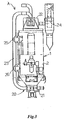
- Fig.1 is one embodiment of a drying apparatus for powdered or granular material according to the present invention
- Fig.1a is its vertical sectional view
- Fig.1b is a cross sectional view of a heat conducting fin.
- the drying apparatus A has a tubular insulation material 2 outside of a hopper body 1 and a heat conducting fin 5 radially projecting plural compartment walls 4 hangs to be supported from a cover 13 with a handle 14 at the center in the hopper body 1.
- the heat conducting fin 5 houses an electric heater 3 and a temperature sensor S in a penetrating path 6 at the center (see Fig.1b).
- Carrier gas fed from an introduction port 7 provided at the upper part of the hopper body 1 is communicated in the penetrating path 6 to be exhausted in the hoper body 1 from plural exhaust ports 8 provided for a plug 10, provided at the bottom, into the hopper body 1.
- the penetrating path 6, the introduction port 7 and the exhaust ports 8 comprise a carrier gas communication path 9.
- the plug 10 is provided for the first-in and first-out manner of powdered or granular material contained in the hopper body 1 by its gravity.
- the introduction port 7 is constructed such that a part of a three-way pipe 11 provided outside of the upper end of the tubular insulation material 2 is opened, the outside end in vertical direction of the three-way pipe 11 is closed, a carrier gas is introduced from the port 11a facing downward and a communication path 12 is formed in horizontal direction into the central penetrating path 6.
- the carrier gas is introduced from the introduction port 7, flows in the horizontal path 12, flows down in the central penetrating path 6, and is exhausted from the port 8. Then, the carrier gas flows upward in the hopper body 1 between the plural compartment walls 4 of the heat conducting fin 5 and is exhausted out of the gas exhaust port 14 at the center of the upper cover 13 into atmosphere.
- the carrier gas used in the present invention is preferably a dry-processed gas like air or an inactive gas and is pressurized into a predetermined pressure by means of a compressor to be introduced in the hopper body 1.
- the carrier gas is introduced into the heat conducting fin 5 at a normal temperature, is heated by the electric heater 3 in the heat conducting fin 5, and is exhausted out of the port 8 provided under the heat conducting fin 5.
- the electric heater 3 is feedback controlled by the temperature sensor S housed in the carrier gas communication path 9, so that the carrier gas is heated into the temperature substantially same as that of the electric heater 3 and the heat conducting fin 5 when it passes through the carrier gas communication path 9.
- the carrier gas is discharged from the port 8 and uniformly dries the powdered or granular material stored in the hopper 1 while passing upward therethrough.
- the carrier gas passes upwardly in the hopper body 1 is exhausted from the upper end of the hopper body 1, however, it may be forcibly exhausted by means of a vacuum pump. In such a case, the carrier gas is controlled its passing amount by the vacuum pump, thereby achieving efficient drying process.
- Bottom part 1a of the hopper body 1 is formed like a reverse cone, and a material discharge port 16 is projected outwardly from a material supply tube 21 connected under the bottom part 1a, the material discharge port 16 being closed with a cap 16a.
- the numeral 17 indicates a straight pipe which is connected to a material supply port when the drying apparatus A is directly attached on the molding machine (not shown). The powdered or granular material stored in the hopper body 1 falls by its gravity to be supplied to the molding machine through a material feed port 17a of the pipe 17.
- the carrier gas introduced from outside is heated while passing in the penetrating path 6 in the heat conducting fin 5, the heated carrier gas heats the powdered or granular material in the hopper body 1 in addition to the heating by the heat conducting fin 5 when passing through the powdered or granular material stored in the hopper body 1 from the exhaust port 8, so that the powdered or granular material can be uniformly heated and dried.
- the carrier gas is not required to be heated before being introduced in the hopper body 1 and is heated in the hopper body as mentioned above. Therefore, a heating source for carrier gas is not necessary, thereby achieving energy efficiency and energy saving.
- Fig.2 shows the structural characteristics of the hopper body of the drying apparatus of the present invention.
- the hopper body 1 is constructed such that the bottom part 1a like a reverse cone provided above the material feed pipe 21 and the tubular container body 1b provided thereon are connected with a hinge 18 and the they are detachable by means of three snap locks 19 provided around the hopper body 1.
- the snap locks 19 are released and the tubular container body 1b is inclined as shown with two-dotted lines in the figure, the inside of the bottom part 1a is exposed, thereby facilitating cleaning in the hopper body 1 with cleaning means.
- the tubular container body 1b is placed on the bottom part 1a and the snap locks 19 are fastened again, the drying apparatus becomes its original shape to prepare a dry process.
- the snap lock 19 is used, however, any known fastening means like bolts and nuts may be used.
- Fig.3 - Fig.5 show a drying apparatus in which a material circulation feeder unit is provided for the hopper body.
- the material circulation feeder unit 20 is constructed such that a material supply means 21 provided under the hopper body 1 and a collector 22 provided above the hopper body 1 are connected with a material transport pipe 23.
- the material supply means 21 has an ejector nozzle by which the powdered or granular material stored in the hopper body 1 is forcibly suck and discharged when a pressurized gas introduced from outside is fed.
- the material supply means 21 is operated to forcibly suck the dried material under the hopper body 1 and to circulate and return the material in the hopper body 1 through the collector 22, thereby preventing a bridging phenomenon in the hopper body 1 before happens.
- One side of the collector 22 is connected to an exhaust pipe 25 having a filter 24, so that the powder or dust are removed by means of the filter 24 and are discharged outside.
- the reference numerals 25 and 26 show a level sensor, 25 indicates a sensor for the highest level, and 26 indicates a sensor for the lowest level. If the powdered or granular material supplied in the hopper body 1 to be dried becomes lower than the lowest level sensor 26, the powdered or granular material is supplied from the material supply source through the collector 22 until the material becomes the detection level for the highest sensor 25.
- the material circulation feeder unit 20 is preferably constructed such that the material transport pipe 23 is made of a flexible tube and is detachably connected to the material supply means 21 and the connection port 22a of the collector 22.
- the material transport pipe 23 is made of a flexible tube, as shown in Fig.4, the tube is removed from the collector 22, a discharge hose 29 is connected by means of a connector 30, the tip open end 29a is directed to the material storage tank 28, and the material supply means 21 is operated. Then, the powdered or granular material remained in the hopper body 1 is discharged into the material storage tank 28, thereby facilitating exchange of materials.
- a drying apparatus for powdered or granular material is comprised of a hopper body with an electric heater in its center, housing therein a heat conducting fin formed with plural compartment walls radially projected therefrom, and a carrier gas communication path provided in the conducting fin, the communication path having an upper introduction port and a lower exhaust port, both connected with a penetrating up and down path provided in the center of the heat conducting fin, wherein a carrier gas is externally introduced and fed into the hopper body.
- the carrier gas introduced from outside is heated substantially the same temperature as that of the heat conducting fin when the carrier gas passes through the central path of the heat conducting fin.
- heated carrier gas heats a powdered or granular material and dries it uniformly in addition to the heat conducting from the heat conducting fin while the carrier gas exhausted from the port moves upward from the bottom of the heat conducting fin into the hopper body and passes through the powdered or granular material.
- the carrier gas is not required to be heated before being introduced in the hopper body, so that a heating source for carrier gas is not necessary, thereby achieving energy efficiency and energy saving.
- Such a drying apparatus is preferably used for uniformly dying a small amount of resin molding material.
- the hoper body is directly attached to the material supply port of an injection molding machine.
- the drying apparatus for powdered or granular material of claim 2 when the material supply operation of the resin material dried in the hopper body into the molding machine is stopped through the material supply port of the molding machine and the material supply means of the material circulation feeder unit is operated, the dried material in the hopper body is forcibly brought out to be circulated and returned in the hopper body through the collector, thereby effectively preventing a bridging phenomenon in the hopper body.
- the material transport pipe is comprised of a flexible hose detachably connected to the collector, so that when the flexible hose can be detached from the collector and the material supply means is operated, the powdered or granular material contained in the hopper body is discharged from the open end of the flexible hose.
- the hopper body is constructed such that a tubular container body is divisibly connected to a bottom part by means of a hinge and a fastening means.
- the tubular container body is inclined by releasing the fastening means and the bottom part is opened so as to be exposed, so that the inside of the hopper body is easily cleaned with a cleaning means, thereby facilitating its maintenance.
Landscapes
- Engineering & Computer Science (AREA)
- Mechanical Engineering (AREA)
- General Engineering & Computer Science (AREA)
- Life Sciences & Earth Sciences (AREA)
- Microbiology (AREA)
- Drying Of Solid Materials (AREA)
- Processing And Handling Of Plastics And Other Materials For Molding In General (AREA)
Applications Claiming Priority (3)
| Application Number | Priority Date | Filing Date | Title |
|---|---|---|---|
| JP2002306360A JP2004144313A (ja) | 2002-10-21 | 2002-10-21 | 粉粒体材料の乾燥装置 |
| JP2002306360 | 2002-10-21 | ||
| PCT/JP2003/013360 WO2004040213A1 (ja) | 2002-10-21 | 2003-10-20 | 粉粒体材料の乾燥装置 |
Publications (2)
| Publication Number | Publication Date |
|---|---|
| EP1566604A1 true EP1566604A1 (de) | 2005-08-24 |
| EP1566604A4 EP1566604A4 (de) | 2012-11-14 |
Family
ID=32211562
Family Applications (1)
| Application Number | Title | Priority Date | Filing Date |
|---|---|---|---|
| EP03754183A Withdrawn EP1566604A4 (de) | 2002-10-21 | 2003-10-20 | Trocknungsvorrichtung f r pulvermaterial |
Country Status (7)
| Country | Link |
|---|---|
| US (1) | US7225556B2 (de) |
| EP (1) | EP1566604A4 (de) |
| JP (1) | JP2004144313A (de) |
| KR (1) | KR20050074474A (de) |
| CN (1) | CN100397013C (de) |
| TW (1) | TWI307656B (de) |
| WO (1) | WO2004040213A1 (de) |
Families Citing this family (18)
| Publication number | Priority date | Publication date | Assignee | Title |
|---|---|---|---|---|
| US7694523B2 (en) | 2004-07-19 | 2010-04-13 | Earthrenew, Inc. | Control system for gas turbine in material treatment unit |
| US7024800B2 (en) | 2004-07-19 | 2006-04-11 | Earthrenew, Inc. | Process and system for drying and heat treating materials |
| US7685737B2 (en) | 2004-07-19 | 2010-03-30 | Earthrenew, Inc. | Process and system for drying and heat treating materials |
| US7024796B2 (en) | 2004-07-19 | 2006-04-11 | Earthrenew, Inc. | Process and apparatus for manufacture of fertilizer products from manure and sewage |
| US7610692B2 (en) | 2006-01-18 | 2009-11-03 | Earthrenew, Inc. | Systems for prevention of HAP emissions and for efficient drying/dehydration processes |
| JP4979538B2 (ja) * | 2007-10-16 | 2012-07-18 | 株式会社神戸製鋼所 | 間接加熱乾燥装置、被乾燥物の間接加熱乾燥方法、ならびに固形燃料の製造方法および製造装置 |
| TWI386352B (zh) * | 2007-12-26 | 2013-02-21 | Hon Hai Prec Ind Co Ltd | 除濕容器 |
| WO2010123010A1 (ja) * | 2009-04-21 | 2010-10-28 | 株式会社松井製作所 | プラスチック成形材料の減圧乾燥装置 |
| AU2011220341B2 (en) | 2010-02-25 | 2015-11-05 | Trewhella Holdings Pty Limited | Scaffolding |
| JP5721958B2 (ja) * | 2010-03-09 | 2015-05-20 | 株式会社松井製作所 | 粉粒体材料の乾燥装置 |
| JP5638351B2 (ja) * | 2010-11-11 | 2014-12-10 | パーパス株式会社 | 樹脂乾燥装置及び樹脂乾燥方法 |
| JP2013221636A (ja) * | 2012-04-13 | 2013-10-28 | Matsui Mfg Co | 粉粒体材料の乾燥装置 |
| JP5830436B2 (ja) * | 2012-06-08 | 2015-12-09 | 株式会社ヨシカワ | 粉粒体供給機における気体送給装置 |
| TW201540481A (zh) * | 2014-04-23 | 2015-11-01 | 研能科技股份有限公司 | 適用於快速成型裝置之粉末加熱組件及其加熱模組 |
| CN104875356B (zh) * | 2015-04-23 | 2017-03-08 | 东莞市联洲知识产权运营管理有限公司 | 一种挤塑机的塑料颗粒供料设备 |
| CN108332513A (zh) * | 2018-01-16 | 2018-07-27 | 昆明恒宇惠源科技有限公司 | 一种颗粒物料分层干燥方法 |
| CN109443902A (zh) * | 2018-10-08 | 2019-03-08 | 四川众望安全环保技术咨询有限公司 | 一种检测样本的烘干装置 |
| EP4587245A1 (de) * | 2022-09-15 | 2025-07-23 | Novatac, INC. | Systeme und verfahren zum trocknen von körnigem material |
Family Cites Families (23)
| Publication number | Priority date | Publication date | Assignee | Title |
|---|---|---|---|---|
| US3313629A (en) * | 1962-08-24 | 1967-04-11 | Blawknox Company | Agglomerating process for powdered food solids or the like |
| DE1604823C3 (de) * | 1966-05-26 | 1973-11-29 | Erich 4010 Hilden Benninghoven | Mit Rauchgasen betriebener Schacht trockner zum Trocknen insbesondere von Zuschlagstoffen als Bestandteile von bituminösem, fur den Straßenbau be stimmtem Mischgut |
| US3756139A (en) * | 1972-04-12 | 1973-09-04 | J Wolens | Popcorn popper |
| FR2221986A5 (en) * | 1973-03-14 | 1974-10-11 | Sifraco Silices Sables Nemours | Vacuum drying granular material - esp. foundry sand which is cooled ready for immediate use |
| JPS5423253A (en) | 1977-07-21 | 1979-02-21 | Mitsui Shipbuilding Eng | Rotary dryer double as direct heating and indirect heating |
| US4304051A (en) * | 1980-04-28 | 1981-12-08 | General Electric Company | Method and apparatus for drying paper-wound bushings |
| JPS58208577A (ja) | 1982-05-29 | 1983-12-05 | 小林 賢治 | 乾燥装置 |
| CA1201263A (en) * | 1983-04-05 | 1986-03-04 | Cactus Machinery Inc. | Apparatus for conditioning hygroscopic plastic material |
| PL143581B1 (en) * | 1984-07-02 | 1988-02-29 | B P Przemyslu Szklarskiego I C | Apparatus for drying loose materials in particular glass-making sands |
| JPS61158410A (ja) | 1984-12-30 | 1986-07-18 | Nissei Plastics Ind Co | 成形機への材料供給方法 |
| JPH0354889Y2 (de) * | 1985-03-23 | 1991-12-05 | ||
| JPH0813462B2 (ja) | 1988-06-28 | 1996-02-14 | 株式会社松井製作所 | 樹脂材料の圧力スイング式熱風乾燥方法及び装置 |
| DE3826047A1 (de) * | 1988-07-30 | 1990-02-01 | Heraeus Schott Quarzschmelze | Vorrichtung zur trocknung feinteiliger feststoffe |
| JPH0813463B2 (ja) | 1988-11-08 | 1996-02-14 | 株式会社松井製作所 | ホッパードライヤー |
| CN2066125U (zh) * | 1989-12-05 | 1990-11-21 | 贾玉山 | 围热式烘干机 |
| CN1060350A (zh) * | 1990-10-05 | 1992-04-15 | 张承业 | 物料热气流分流干燥装置 |
| JP3305950B2 (ja) | 1996-04-25 | 2002-07-24 | スズキ株式会社 | ホッパードライヤー |
| US5987769A (en) * | 1996-04-30 | 1999-11-23 | Carter Day International, Inc. | Centrifugal dryer |
| AU2883197A (en) * | 1996-05-29 | 1998-01-05 | Webb Technologies Ltd. | Apparatus for conditioning pellets |
| ITPD980154A1 (it) * | 1998-06-18 | 1999-12-18 | Agrex Srl | Essicatoio per cereali e materiali granulari in genere. |
| JP3773675B2 (ja) | 1998-10-28 | 2006-05-10 | 株式会社松井製作所 | 粉粒体材料の真空式自動連続除湿乾燥装置 |
| JP3791653B2 (ja) | 1998-10-28 | 2006-06-28 | 株式会社松井製作所 | 熱伝導を用いた粉粒体材料の除湿乾燥装置 |
| JP3284108B2 (ja) * | 1999-04-21 | 2002-05-20 | プラスメート株式会社 | 樹脂ペレットの熱風乾燥装置 |
-
2002
- 2002-10-21 JP JP2002306360A patent/JP2004144313A/ja active Pending
-
2003
- 2003-10-20 EP EP03754183A patent/EP1566604A4/de not_active Withdrawn
- 2003-10-20 WO PCT/JP2003/013360 patent/WO2004040213A1/ja not_active Ceased
- 2003-10-20 CN CNB2003801017917A patent/CN100397013C/zh not_active Expired - Fee Related
- 2003-10-20 TW TW092129030A patent/TWI307656B/zh not_active IP Right Cessation
- 2003-10-20 KR KR1020057005893A patent/KR20050074474A/ko not_active Ceased
- 2003-10-20 US US10/532,365 patent/US7225556B2/en not_active Expired - Fee Related
Also Published As
| Publication number | Publication date |
|---|---|
| WO2004040213A1 (ja) | 2004-05-13 |
| CN1705856A (zh) | 2005-12-07 |
| TWI307656B (en) | 2009-03-21 |
| JP2004144313A (ja) | 2004-05-20 |
| TW200414943A (en) | 2004-08-16 |
| US7225556B2 (en) | 2007-06-05 |
| EP1566604A4 (de) | 2012-11-14 |
| CN100397013C (zh) | 2008-06-25 |
| KR20050074474A (ko) | 2005-07-18 |
| US20060123657A1 (en) | 2006-06-15 |
Similar Documents
| Publication | Publication Date | Title |
|---|---|---|
| EP1566604A1 (de) | Trocknungsvorrichtung f r pulvermaterial | |
| US7703217B2 (en) | Drying-storing apparatus for powdered or granular material and feeding system for powdered or granular material | |
| EP0997695B1 (de) | Automatische Vakuumentfeuchtungs- und -trocknungsvorrichtung für pulverförmiges oder körniges Gut | |
| JP5130338B2 (ja) | 粉粒体材料の排出装置、及びこれを備えた粉粒体材料の輸送システム | |
| KR101541621B1 (ko) | 건조장치 및 건조방법 | |
| US5033208A (en) | Hopper dryer | |
| CN101825389B (zh) | 一种采用惰性气体输出物料的沸腾干燥机 | |
| CN107615626A (zh) | 旋转电机的气体干燥器 | |
| CN110686466B (zh) | 颗粒物料烘干装置、烘干设备、颗粒物料及粉料烘干工艺 | |
| CN105264318A (zh) | 在集装箱内蒸发液体和干燥固定床颗粒并且回收冷凝水的方法 | |
| CN115892648A (zh) | 物料球的分装装置 | |
| CN220390003U (zh) | 一种工程塑料颗粒除湿干燥冷却系统 | |
| JP4132462B2 (ja) | 粉粒体の乾燥装置 | |
| CN216080869U (zh) | 一种石油化工固体物料干燥装置 | |
| KR100551142B1 (ko) | 합성수지 재료의 건조 및 이송 장치 | |
| KR100351681B1 (ko) | 자동 진공건조장치 | |
| CN206291692U (zh) | 一种具有料位检测功能的干燥系统 | |
| CN218270084U (zh) | 一种热熔胶颗粒干燥机 | |
| CN219934499U (zh) | 一种干燥分离装置 | |
| JP2011194623A (ja) | 乾燥装置 | |
| CN213067000U (zh) | 一种用于活性炭生产的半成品输送装置 | |
| JP4132469B2 (ja) | 減圧乾燥装置 | |
| JPS6214557Y2 (de) | ||
| JP2000313526A (ja) | 粉粒体供給装置 | |
| CN206073616U (zh) | 一种干燥机 |
Legal Events
| Date | Code | Title | Description |
|---|---|---|---|
| PUAI | Public reference made under article 153(3) epc to a published international application that has entered the european phase |
Free format text: ORIGINAL CODE: 0009012 |
|
| 17P | Request for examination filed |
Effective date: 20050520 |
|
| AK | Designated contracting states |
Kind code of ref document: A1 Designated state(s): AT BE BG CH CY CZ DE DK EE ES FI FR GB GR HU IE IT LI LU MC NL PT RO SE SI SK TR |
|
| AX | Request for extension of the european patent |
Extension state: AL LT LV MK |
|
| RIN1 | Information on inventor provided before grant (corrected) |
Inventor name: TAKINO, YORINOBUC/O K.K. MATSUI SEISAKUSHO Inventor name: OKUDA, TAKAYUKIC/O K.K. MATSUI SEISAKUSHO Inventor name: SHIMIZU, MOTOHARUC/O K.K.MATSUI SEISAKUSHO Inventor name: TADA, HIROSHIC/O K.K. MATSUI SEISAKUSHO |
|
| DAX | Request for extension of the european patent (deleted) | ||
| A4 | Supplementary search report drawn up and despatched |
Effective date: 20121015 |
|
| RIC1 | Information provided on ipc code assigned before grant |
Ipc: F26B 17/16 20060101ALI20121009BHEP Ipc: F26B 17/14 20060101ALI20121009BHEP Ipc: F26B 3/26 20060101AFI20121009BHEP Ipc: F26B 9/08 20060101ALI20121009BHEP |
|
| STAA | Information on the status of an ep patent application or granted ep patent |
Free format text: STATUS: THE APPLICATION IS DEEMED TO BE WITHDRAWN |
|
| 18D | Application deemed to be withdrawn |
Effective date: 20130115 |