EP1566483B1 - Plaque de pose - Google Patents
Plaque de pose Download PDFInfo
- Publication number
- EP1566483B1 EP1566483B1 EP05003480A EP05003480A EP1566483B1 EP 1566483 B1 EP1566483 B1 EP 1566483B1 EP 05003480 A EP05003480 A EP 05003480A EP 05003480 A EP05003480 A EP 05003480A EP 1566483 B1 EP1566483 B1 EP 1566483B1
- Authority
- EP
- European Patent Office
- Prior art keywords
- plate
- longitudinal
- laying
- corrugation
- plates
- Prior art date
- Legal status (The legal status is an assumption and is not a legal conclusion. Google has not performed a legal analysis and makes no representation as to the accuracy of the status listed.)
- Expired - Lifetime
Links
- 230000008878 coupling Effects 0.000 claims abstract description 24
- 238000010168 coupling process Methods 0.000 claims abstract description 24
- 238000005859 coupling reaction Methods 0.000 claims abstract description 24
- 229920003023 plastic Polymers 0.000 claims abstract description 6
- 239000004033 plastic Substances 0.000 claims abstract description 6
- 230000002093 peripheral effect Effects 0.000 claims abstract description 3
- 239000000725 suspension Substances 0.000 claims description 2
- 206010000496 acne Diseases 0.000 claims 3
- 238000003780 insertion Methods 0.000 claims 2
- 230000037431 insertion Effects 0.000 claims 2
- 238000005259 measurement Methods 0.000 claims 1
- 238000009434 installation Methods 0.000 abstract description 30
- 241000388002 Agonus cataphractus Species 0.000 description 6
- 238000000034 method Methods 0.000 description 3
- 238000005452 bending Methods 0.000 description 2
- 239000000463 material Substances 0.000 description 2
- 239000004698 Polyethylene Substances 0.000 description 1
- 238000004140 cleaning Methods 0.000 description 1
- 230000006378 damage Effects 0.000 description 1
- 238000006073 displacement reaction Methods 0.000 description 1
- 239000002184 metal Substances 0.000 description 1
- 210000001331 nose Anatomy 0.000 description 1
- -1 polyethylene Polymers 0.000 description 1
- 229920000573 polyethylene Polymers 0.000 description 1
- 230000029058 respiratory gaseous exchange Effects 0.000 description 1
- 239000002689 soil Substances 0.000 description 1
- 125000006850 spacer group Chemical group 0.000 description 1
- 239000000758 substrate Substances 0.000 description 1
- XLYOFNOQVPJJNP-UHFFFAOYSA-N water Substances O XLYOFNOQVPJJNP-UHFFFAOYSA-N 0.000 description 1
Images


Classifications
-
- E—FIXED CONSTRUCTIONS
- E01—CONSTRUCTION OF ROADS, RAILWAYS, OR BRIDGES
- E01C—CONSTRUCTION OF, OR SURFACES FOR, ROADS, SPORTS GROUNDS, OR THE LIKE; MACHINES OR AUXILIARY TOOLS FOR CONSTRUCTION OR REPAIR
- E01C5/00—Pavings made of prefabricated single units
- E01C5/20—Pavings made of prefabricated single units made of units of plastics, e.g. concrete with plastics, linoleum
-
- E—FIXED CONSTRUCTIONS
- E01—CONSTRUCTION OF ROADS, RAILWAYS, OR BRIDGES
- E01C—CONSTRUCTION OF, OR SURFACES FOR, ROADS, SPORTS GROUNDS, OR THE LIKE; MACHINES OR AUXILIARY TOOLS FOR CONSTRUCTION OR REPAIR
- E01C2201/00—Paving elements
- E01C2201/12—Paving elements vertically interlocking
Definitions
- the invention relates to a laying plate according to the preamble of claim 1, as used for supporting or covering the floor outdoors.
- the object of the invention is to provide a laying plate o. Specify genus and a laying plate assembly by which it is possible to quickly provide a clean floor cover that allows a safe appearance on this.
- the laying plate has on its upper side a substantially closed cover plate, which is provided with at least one linearly extending wave structure in the longitudinal and transverse directions, wherein the wave structures are brought in their longitudinal extent with their ends respectively to a Dehnungsbogenabêt of the outer frame near and to these are spaced over their entire arc length via a transverse slot. Due to the arrangement of the intersecting wave structures and their respective free outlet in the direction of the Dehnbögen the outer walls a corresponding compliance and the cover plate is ensured. In addition, the wave structures simultaneously form an effective slip obstacle. Through the slots at the end of the waves cleaning or rain water can quickly drain from the plate surface into the ground. Through these openings but moisture underneath can easily evaporate, so that it can be said here that the substrate can sufficiently "breathe” even after application of the installation plates according to the invention.
- this "breathing" is further promoted by the fact that there is in each case a vertical breakthrough at the crossing points of the longitudinal and transverse wave structures, preferably with a diameter approximately equal to the distance between two wave crests.
- a wave structure consists of several waves, which extend over the entire length of the wall-expansion arc, wherein preferably three troughs are provided with intermediate two wave crests.
- the entire length of the expansion arch remains actively compliant, and this compliance is transmitted to its cover plate in the same way by the wave structure designed for approximately arc length.
- the cover plate is divided into a plurality of uniform rectangular fields, preferably in square fields.
- each support wall rectangles are provided on the underside of the plate fields.
- at least one of the walls of the Stauerrechtecke a straight portion of the outer frame at the outer frame directly adjacent fields.
- the support rectangles are designed larger and their walls brought close to the wave structures to give these fields the necessary slip resistance.
- the plates are additionally provided on their underside with diagonal, transverse or longitudinal ribs or supports. These ribs or supports prevent central bending of the fields within their support frame, so that they do not break even with greater central load.
- a plate is divided into six, nine twelve or more fields, wherein z. B. by a square shape with z. B. nine fields an optimal Verlegerasttation is obtained.
- By additional arrangement on the fields of nubs - longitudinal and cross knobs - such.
- maximum tread and slip resistance is produced by nubs, waves and material.
- a laying plate assembly using the above installation plates is obtained according to the invention, when also strip-shaped coupling adapter are provided, the length of which is at least the length of a laying plate or a plurality of plates coupled to each other, such.
- These adapters have on their longitudinal sides coupling means corresponding to those of the installation plates. However, only the coupling elements on one side of the adapter allow a latching coupling with the plates, while the other side only permit vertical pushing together without latching.
- the one adapter wall coupling openings no undercuts or snap-in lugs are assigned, so that the imported coupling hooks of the plates indeed engage by clamping, but can not engage on their locking lugs.
- the plate connection can be made on this coupling side by simply moving in the Z direction, without special effort and danger of destruction and without the use of tools.
- the adapter may have a downwardly open U-shaped cross-section and have on its upwardly facing outer surface anti-slip nubs or corrugations.
- this anti-slip adapter surface should not be higher than that of the panels and the wave structures of the bonded panels.
- the installation plates according to the invention can be pre-assembled in a particularly advantageous manner to large plates, with several, for example, nine or twelve square plates are firmly snap-coupled to a large square.
- adapters are pushed vertically over their coupling hooks and firmly locked.
- these large plates provided with adapter can only be plugged together by another vertical slide, without engaging behind, with another plate, and so quickly and easily a large area can be covered clean and appealing. If the cover is to be removed again, then you do not have to plate by plate with the help of tools be decoupled, but it will be the individual plates or the large plates only posted to the intervening adapters of each other.
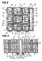
- a laying plate 1 has a rectangular outer frame 2, the four walls 3 each have two arc sections 4, between which straight wall sections 5 are present. On the inner sides of the straight wall sections 5, each assigned to this, in the X and Y direction extending support walls 6 and 7 are provided, which form together with the associated wall sections 5 Stauerrechtecke 8 and 9, whose function will be seen in the further. At the upper portion of the support rectangles 8, 9, diagonal ribs 10 or transverse / longitudinal ribs 11 are provided. In the interior, an inner Stauereck 12 is arranged, which is crossed by diagonal ribs 10, which in turn on its underside, except for the support surface vertically downwardly guided supports 13 have.
- the laying plate 1 has on its upper side a cover plate 15, which are traversed by longitudinal and transverse wave structures 16 and 17.
- These wave structures each consist of several waves with wave arcs 18 and wave troughs 19, wherein in this embodiment two wave crests 19, three wave troughs 18 are assigned are.
- the wave crests and wave troughs 18 and 19 existing wave structures 16, 17 have a width which is approximately equal to the length of the arcuate portions 4 of the outer walls 3.
- the respective longitudinal end of a wave structure 16, 17 is brought close to the arc sections 4 and leave only a narrow gap slot 20 free for these.
- an opening 21 is provided in each case, which, as shown Fig. 3 is more apparent, is circular. Of course, it can also be rectangular.
- the wave structures 16, 17 define in the cover plate 15 substantially planar rectangular fields 22, on the upper side of each longitudinal and transverse knobs 23 and 24 are arranged.
- a rectangular box 22 is assigned a supporting rectangle 8, 9, 12 or projects on the lower sides thereof.
- This Stauerecke 8, 9, 12 serve to support the rectangular fields 22 on the ground, in addition, the ribs 10, 11 counteract bending or even breaking the rectangular fields under load.
- the inner rectangular field, together with its Stauereck 12, by the surrounding wave structures 16, 17 "floating" is stored. It can thus at least slightly yield in all directions as a substantially independent box part by the wave or bellows attachment.
- corrugations 16 and 17 are clearly shown, especially as they are composed of troughs 19 and corrugation peaks 18, each free between the support rectangles 8, 9 and 12, without any wall supports extending transverse to their longitudinal orientation to stand.
- Fig. 3 is a square installation plate 1, similar to in Fig. 1 shown in bottom view, which is coupled to an adapter 32.
- the adapter 32 has substantially the same coupling device parts as the installation plate 1, namely on the one hand passages 29, engage in the hook parts 25 of the installation plate 1 and on the other hand has hook parts 25, via which the adapter 32 is coupled to the installation plate 1 is.
- the provided here on the wall 34 here hook parts 25 of the adapter 32 are practically inseparable locked in the installation plate 1, while the bushings 29 of the outer wall 33 of the adapter in a subsequent, not shown here laying plate is pushed vertically, but it does not latch because on the inside of the wall 33 no undercuts are provided for locking, as still closer Fig.
- the adapter 32 has a downwardly open box shape, which is formed in cross-section substantially U-shaped in the wall, as also out Fig. 4 and 5 will be more apparent.
- Out Fig. 3 is also good to see that the laying plate 1 shown in the drawing is designed square and how at the bottom of the respective support frame 8, 9 are arranged, each straight wall sections 5 of the outer frame 2 assigned.
- the inner rectangular rectangle 12 supporting or supporting the inner rectangular field 22 is surrounded by the intersecting wave structures 16, 17 and openings 21 are provided as in the crossing points of the wave structures.
- the arrangement of the diagonal, transverse and longitudinal ribs 10, 11 can be seen and how they are integrated into the total formed by the Stitzrechtecke 8, 9 and 12 geometric pattern with and for a secure support of the cover plate 15 and their individual rectangular fields 22 provide.
- FIG. 4 It can be seen how two installation plates 1, 1 'are coupled to one another via an adapter 32.
- the cross-sectionally U-shaped adapter 32 engages around the wall portion 5 of the outer frame 2 of the installation plate 1 'on the one hand by the hook portions 25 provided on its left wall 34 and is firmly suspended or latched with its hook nose 28 into the undercut 30 of the wall. This detent is practically no longer solvable, without fear that the hook parts 25 are destroyed.
- the here right wall 33 of the adapter 32 is encompassed by the hook portions 25 of the wall portion 5 of the outer frame 2 of the right installation plate 1, wherein it can be seen that the wall 33 is made smooth on its inside, so has no undercut, in which the hook nose 28 of the hook member 25 could snap.
- the hook nose 28 is only under elastic pressure on the inside of the wall 33 and can be moved vertically, whereby the connection between the installation plate 1 and the adapter 32 can be quickly and easily solved by vertical displacement of the two parts to each other.
- At the top of the adapter 32 also has anti-slip nubs 35.
Landscapes
- Engineering & Computer Science (AREA)
- Architecture (AREA)
- Civil Engineering (AREA)
- Structural Engineering (AREA)
- Floor Finish (AREA)
- Sewage (AREA)
- Revetment (AREA)
- Glass Compositions (AREA)
- Polishing Bodies And Polishing Tools (AREA)
- Road Paving Structures (AREA)
- Cultivation Of Plants (AREA)
Claims (12)
- Plaque de pose, notamment en matière plastique, comprenant- un cadre (2) extérieur faisant le tour et ayant des parties (4) arquées courbées vers l'intérieur, comme éléments de dilatation des parois du cadre,- des dispositifs d'accouplement sur la face intérieure des parois du cadre, constitués de parties (25) en crochet en forme de T sur deux parois de cadre voisines et de traversées (29) sur les deux autres parois du cadre,- des parois (6, 7) d'appui longitudinale et transversale, qui munissent l'intérieur de la plaque de rectangles,caractérisée,- en ce que la face supérieure de la plaque a une plaque (15) de couverture sensiblement fermée,- en ce que la plaque (15) de couverture est munie d'au moins une structure (16, 17) ondulée dans la direction longitudinale et dans la direction transversale, qui a respectivement au moins un sommet (18) d'ondulation et un creux (19) d'ondulation,- dans laquelle les structures (16, 17) ondulées vont dans leur étendue longitudinale respectivement jusqu'à près des parties (4) arquées des parois (3) de cadre opposées l'une à l'autre et n'en sont séparées que par une fente (20) étroite le long de la partie (4) arquée.
- Plaque de pose suivant la revendication 1, caractérisée en ce que, respectivement une structure (16, 17) ondulée s'étend par sa largeur à peu près sur toute la longueur d'une partie (4) arquée et est formée de préférence de deux sommets (18) d'ondulation et de trois creux (19) d'ondulation.
- Plaque de pose suivant la revendication 1, caractérisée en ce que lors de la rencontre des structures (16, 17) ondulées longitudinales et transversales, il y a respectivement une traversée (21) verticale dans la plaque (15) de couverture, de préférence une traversée circulaire.
- Plaque de pose suivant la revendication 1, caractérisée en ce que la structure (16, 17) ondulée subdivise la plaque (15) de couverture en des domaines (22) rectangulaires uniformes, de préférence en des domaines carrés.
- Plaque de pose suivant la revendication 1 à 4, caractérisée en ce que, les domaines (22) extérieurs voisins directement du cadre (2) extérieur sont munis respectivement d'un rectangle (8, 9) de paroi d'appui, au moins l'une des parois étant une partie (5) rectiligne du cadre (2) extérieur et en ce qu'au moins un domaine (22) intérieur a sur sa face inférieure respectivement un rectangle (12) inférieur de paroi d'appui, qui va respectivement jusqu'aux ondulations (16, 17) qui l'entourent.
- Plaque de pose suivant la revendication 5, caractérisée en ce qu'au domaine (22) de la plaque de couverture et aux rectangles (8, 9, 12) de parois les soutenant vers le bas sont associés des nervures ou des appuis (10 à 13) transversaux ou longitudinaux.
- Plaque de pose suivant l'une des revendications 1 à 6
caractérisée en ce que, la plaque (15) de couverture est subdivisée en neuf domaines par deux structures (16) ondulées longitudinales et par deux structures (17) ondulées transversales. - Plaque de pose suivant la revendication 7, caractérisée en ce que,
les domaines (22) de la plaque ont une constitution et un agencement carré et, de préférence, il est prévu des dimensions extérieures de plaque d'environ 330 x 330 x 30 mm ou d'environ 330 x 330 x 50 mm. - Plaque de pose suivant l'une des revendications précédentes caractérisée en ce que,
sur la face supérieure des domaines (22) sont prévus plusieurs bossages (23, 24) longitudinaux et transversaux en alternance, comme ils sont connus par exemple pour diverses plaques de couverture en tôle et en ce que des sommets d'ondulation et des bossages ont une hauteur maximum à peu près égale. - Agencement de plaques de pose en utilisant des plaques de pose suivant au moins l'une des revendications 1 à 9, caractérisé,- en ce qu'il est prévu un adaptateur (32) de couplage en forme de baguette, dont la longueur est au moins celle de la longueur d'une plaque (1) de pose en matière plastique ou de plusieurs plaques accouplées solidement les unes à côté des autres,- qui a sur ses grands côtés des dispositifs (25, 30) d'accouplement, qui correspondent à ceux des plaques (1),- mais dans lequel les éléments (25) d'accouplement de l'une des faces (34) de l'adaptateur sont conçus pour s'encliqueter (29, 30) de manière fixe avec la plaque (1), tandis que ceux de l'autre face (33) ne permettent sans encliquetage qu'un coulissement ou un accrochage vertical de serrage amovible sur une plaque (1).
- Agencement de plaques de pose suivant la revendication 10, caractérisé
en ce que l'adaptateur (32) a une section transversale en forme de U, ouverte vers le bas, et a des bossages (35) ou des stries d'anti-glissement sur sa surface extérieure tournée vers le haut. - Agencement de plaques de pose en matière plastique suivant la revendication 10 ou 11, caractérisé
en ce que des plaques (36) de grande dimension pré-montées sont rassemblées en étant constituées de plusieurs, par exemple de neuf ou douze plaques (1) encliquetées solidement ensemble en un carré ou en un rectangle de grande dimension et de deux adaptateurs oblongs ou de plusieurs adaptateurs (32) courts correspondants qui sont encliquetés solidement sur respectivement les deux parois (3) de cadre se rencontrant, de sorte que la paroi (33) d'adaptateur qui ne peut pas être encliquetée et qui est tournée vers l'extérieur est à la disposition de respectivement une autre plaque (36) de grande dimension pour l'assemblage par coulissement vertical.
Applications Claiming Priority (2)
| Application Number | Priority Date | Filing Date | Title |
|---|---|---|---|
| DE102004008130A DE102004008130B3 (de) | 2004-02-18 | 2004-02-18 | Verlegeplatte |
| DE102004008130 | 2004-02-18 |
Publications (3)
| Publication Number | Publication Date |
|---|---|
| EP1566483A2 EP1566483A2 (fr) | 2005-08-24 |
| EP1566483A3 EP1566483A3 (fr) | 2006-03-22 |
| EP1566483B1 true EP1566483B1 (fr) | 2009-07-22 |
Family
ID=34706856
Family Applications (1)
| Application Number | Title | Priority Date | Filing Date |
|---|---|---|---|
| EP05003480A Expired - Lifetime EP1566483B1 (fr) | 2004-02-18 | 2005-02-18 | Plaque de pose |
Country Status (3)
| Country | Link |
|---|---|
| EP (1) | EP1566483B1 (fr) |
| AT (1) | ATE437268T1 (fr) |
| DE (2) | DE102004008130B3 (fr) |
Families Citing this family (10)
| Publication number | Priority date | Publication date | Assignee | Title |
|---|---|---|---|---|
| DE102005019039A1 (de) | 2005-04-23 | 2006-10-26 | Leibfahrt Handelsgesellschaft | Verlegeplatte |
| DE102007036005A1 (de) * | 2007-07-30 | 2008-10-23 | Alois Dold | Bodenbefestigungsplatte |
| DE102009056079A1 (de) * | 2009-11-30 | 2011-06-01 | Kurt Stumpf | Kunststoff-Bodenplatte |
| DE202010005276U1 (de) | 2010-04-21 | 2010-09-30 | Purus Arzberg Gmbh | Verlegeplatte |
| DE102010016570A1 (de) | 2010-04-21 | 2011-10-27 | Purus Arzberg Gmbh | Verlegeplatte |
| GB2481004B (en) * | 2010-06-07 | 2015-06-10 | Oxford Plastic Sys Ltd | Barrier arrangement |
| DE202010007977U1 (de) | 2010-07-02 | 2010-12-09 | Purus Arzberg Gmbh | Verlegeplatte für Nutzflächen |
| US8979418B2 (en) | 2012-03-12 | 2015-03-17 | Oxford Plastic Systems Limited | Barrier |
| DE202014106285U1 (de) * | 2014-12-28 | 2015-06-03 | PURUS PLASTICS GmbH | Kunststoff-Mehrzweckbauteil |
| DE202019004560U1 (de) * | 2019-11-08 | 2021-02-10 | Jürgen Heckelsmüller | System zur Befestigung von Outdoorflächen und eine damit befestigte Fläche |
Family Cites Families (9)
| Publication number | Priority date | Publication date | Assignee | Title |
|---|---|---|---|---|
| DE2614095A1 (de) * | 1976-04-01 | 1977-10-06 | Michael Friederichsen | Pflasterelement |
| DE3841656A1 (de) * | 1988-12-10 | 1990-08-09 | Spiess Kunststoff Recycling | Doppelseitig verlegbare gitterplatte aus kunststoff, insbesondere aus recycling - kunststoff |
| DE3923656A1 (de) * | 1989-07-18 | 1991-01-31 | Spiess Kunststoff Recycling | Verlegplatte aus kunststoff, insbesondere aus recycling-kunststoff |
| DE4143228A1 (de) * | 1991-12-31 | 1993-07-01 | Norbert Funke | Vorrichtung zur befestigung von rasenwegen |
| DE9208359U1 (de) * | 1992-06-25 | 1992-10-15 | RPS Recycling Produkte Systeme GmbH, 95615 Marktredwitz | Aus Kunststoff bestehendes Mehrzweckbauteil |
| DE9403484U1 (de) * | 1994-03-02 | 1995-03-30 | Pelikan Gmbh, 30177 Hannover | Formstein |
| DE19529473C1 (de) * | 1995-08-11 | 1996-08-22 | Wolfgang Weber | Mehrzweckbauteil mit Federelementen |
| AU6432098A (en) * | 1998-02-17 | 1999-08-30 | Sian Ghee Alan Lee | A grid structure |
| DE19938950A1 (de) * | 1999-08-17 | 2001-02-22 | Staebler Gmbh | Erdbodenabdeckung |
-
2004
- 2004-02-18 DE DE102004008130A patent/DE102004008130B3/de not_active Expired - Fee Related
-
2005
- 2005-02-18 DE DE502005007732T patent/DE502005007732D1/de not_active Expired - Lifetime
- 2005-02-18 EP EP05003480A patent/EP1566483B1/fr not_active Expired - Lifetime
- 2005-02-18 AT AT05003480T patent/ATE437268T1/de not_active IP Right Cessation
Also Published As
| Publication number | Publication date |
|---|---|
| ATE437268T1 (de) | 2009-08-15 |
| EP1566483A2 (fr) | 2005-08-24 |
| DE502005007732D1 (de) | 2009-09-03 |
| EP1566483A3 (fr) | 2006-03-22 |
| DE102004008130B3 (de) | 2005-09-15 |
Similar Documents
| Publication | Publication Date | Title |
|---|---|---|
| DE102005016832B4 (de) | Verstärkte Entwässerungsgitteranordnung | |
| DE102005028524B4 (de) | Entwässerungsgitteranordnung | |
| EP0816564A2 (fr) | Renforcement pour aires de circulation avec des pavés ou des dalles | |
| EP1366550B1 (fr) | Couvre-cables | |
| DE102004008130B3 (de) | Verlegeplatte | |
| DE2803892A1 (de) | Bodenbelagsplatte und damit hergestellter bodenbelag | |
| EP2327846A2 (fr) | Plaque de fond en matière synthétique | |
| EP1785575B1 (fr) | Connecteur | |
| DE202011102524U1 (de) | Fugenabdichtvorrichtung für den Betonbau | |
| DE202011051047U1 (de) | Ablaufanordnung | |
| DE8705002U1 (de) | Einbauhilfe zum Abschalen eines Betonbauteils in einem Anschlußbereich | |
| EP1715100B1 (fr) | Elément de pavage | |
| DE202009010493U1 (de) | Flächenbegrenzung | |
| DE19735258C2 (de) | Haltegitter zum Halten eines Rohres für eine Flächenheizung oder Flächenkühlung mit gebogenen und geradlinigen Abschnitten | |
| DE19828082A1 (de) | Verdrahtungskanal aus Kunststoff | |
| DE9001890U1 (de) | Schalung für den Betonbau | |
| DE19704425A1 (de) | Kunststeinelement | |
| DE8117704U1 (de) | "Fußbodenplatte" | |
| EP1191160A1 (fr) | Dispositif d'écoulement | |
| EP2071098A2 (fr) | Elément en matière plastique pour former un sol grillagé | |
| DE1960918C3 (de) | Aufrollbarer Stabrost zur Abdeckung räumlich begrenzter Vertiefungen | |
| AT395625B (de) | Bodenrost aus kunststoff | |
| DE29511551U1 (de) | Gitterrostelement | |
| EP0908568A1 (fr) | Dispositif de verrouillage pour des grilles dans des cadres | |
| DE20009796U1 (de) | Gitterrost |
Legal Events
| Date | Code | Title | Description |
|---|---|---|---|
| PUAI | Public reference made under article 153(3) epc to a published international application that has entered the european phase |
Free format text: ORIGINAL CODE: 0009012 |
|
| AK | Designated contracting states |
Kind code of ref document: A2 Designated state(s): AT BE BG CH CY CZ DE DK EE ES FI FR GB GR HU IE IS IT LI LT LU MC NL PL PT RO SE SI SK TR |
|
| AX | Request for extension of the european patent |
Extension state: AL BA HR LV MK YU |
|
| PUAL | Search report despatched |
Free format text: ORIGINAL CODE: 0009013 |
|
| AK | Designated contracting states |
Kind code of ref document: A3 Designated state(s): AT BE BG CH CY CZ DE DK EE ES FI FR GB GR HU IE IS IT LI LT LU MC NL PL PT RO SE SI SK TR |
|
| AX | Request for extension of the european patent |
Extension state: AL BA HR LV MK YU |
|
| 17P | Request for examination filed |
Effective date: 20060214 |
|
| AKX | Designation fees paid |
Designated state(s): AT BE BG CH CY CZ DE DK EE ES FI FR GB GR HU IE IS IT LI LT LU MC NL PL PT RO SE SI SK TR |
|
| GRAP | Despatch of communication of intention to grant a patent |
Free format text: ORIGINAL CODE: EPIDOSNIGR1 |
|
| GRAS | Grant fee paid |
Free format text: ORIGINAL CODE: EPIDOSNIGR3 |
|
| GRAA | (expected) grant |
Free format text: ORIGINAL CODE: 0009210 |
|
| AK | Designated contracting states |
Kind code of ref document: B1 Designated state(s): AT BE BG CH CY CZ DE DK EE ES FI FR GB GR HU IE IS IT LI LT LU MC NL PL PT RO SE SI SK TR |
|
| REG | Reference to a national code |
Ref country code: GB Ref legal event code: FG4D Free format text: NOT ENGLISH |
|
| REG | Reference to a national code |
Ref country code: CH Ref legal event code: EP |
|
| REG | Reference to a national code |
Ref country code: IE Ref legal event code: FG4D |
|
| REF | Corresponds to: |
Ref document number: 502005007732 Country of ref document: DE Date of ref document: 20090903 Kind code of ref document: P |
|
| NLV1 | Nl: lapsed or annulled due to failure to fulfill the requirements of art. 29p and 29m of the patents act | ||
| PG25 | Lapsed in a contracting state [announced via postgrant information from national office to epo] |
Ref country code: IS Free format text: LAPSE BECAUSE OF FAILURE TO SUBMIT A TRANSLATION OF THE DESCRIPTION OR TO PAY THE FEE WITHIN THE PRESCRIBED TIME-LIMIT Effective date: 20091122 Ref country code: FI Free format text: LAPSE BECAUSE OF FAILURE TO SUBMIT A TRANSLATION OF THE DESCRIPTION OR TO PAY THE FEE WITHIN THE PRESCRIBED TIME-LIMIT Effective date: 20090722 Ref country code: ES Free format text: LAPSE BECAUSE OF FAILURE TO SUBMIT A TRANSLATION OF THE DESCRIPTION OR TO PAY THE FEE WITHIN THE PRESCRIBED TIME-LIMIT Effective date: 20091102 Ref country code: SE Free format text: LAPSE BECAUSE OF FAILURE TO SUBMIT A TRANSLATION OF THE DESCRIPTION OR TO PAY THE FEE WITHIN THE PRESCRIBED TIME-LIMIT Effective date: 20090722 Ref country code: LT Free format text: LAPSE BECAUSE OF FAILURE TO SUBMIT A TRANSLATION OF THE DESCRIPTION OR TO PAY THE FEE WITHIN THE PRESCRIBED TIME-LIMIT Effective date: 20090722 |
|
| PG25 | Lapsed in a contracting state [announced via postgrant information from national office to epo] |
Ref country code: NL Free format text: LAPSE BECAUSE OF FAILURE TO SUBMIT A TRANSLATION OF THE DESCRIPTION OR TO PAY THE FEE WITHIN THE PRESCRIBED TIME-LIMIT Effective date: 20090722 Ref country code: SI Free format text: LAPSE BECAUSE OF FAILURE TO SUBMIT A TRANSLATION OF THE DESCRIPTION OR TO PAY THE FEE WITHIN THE PRESCRIBED TIME-LIMIT Effective date: 20090722 Ref country code: PL Free format text: LAPSE BECAUSE OF FAILURE TO SUBMIT A TRANSLATION OF THE DESCRIPTION OR TO PAY THE FEE WITHIN THE PRESCRIBED TIME-LIMIT Effective date: 20090722 |
|
| REG | Reference to a national code |
Ref country code: IE Ref legal event code: FD4D |
|
| PG25 | Lapsed in a contracting state [announced via postgrant information from national office to epo] |
Ref country code: BG Free format text: LAPSE BECAUSE OF FAILURE TO SUBMIT A TRANSLATION OF THE DESCRIPTION OR TO PAY THE FEE WITHIN THE PRESCRIBED TIME-LIMIT Effective date: 20091022 Ref country code: PT Free format text: LAPSE BECAUSE OF FAILURE TO SUBMIT A TRANSLATION OF THE DESCRIPTION OR TO PAY THE FEE WITHIN THE PRESCRIBED TIME-LIMIT Effective date: 20091122 |
|
| PG25 | Lapsed in a contracting state [announced via postgrant information from national office to epo] |
Ref country code: CZ Free format text: LAPSE BECAUSE OF FAILURE TO SUBMIT A TRANSLATION OF THE DESCRIPTION OR TO PAY THE FEE WITHIN THE PRESCRIBED TIME-LIMIT Effective date: 20090722 Ref country code: IE Free format text: LAPSE BECAUSE OF FAILURE TO SUBMIT A TRANSLATION OF THE DESCRIPTION OR TO PAY THE FEE WITHIN THE PRESCRIBED TIME-LIMIT Effective date: 20090722 Ref country code: RO Free format text: LAPSE BECAUSE OF FAILURE TO SUBMIT A TRANSLATION OF THE DESCRIPTION OR TO PAY THE FEE WITHIN THE PRESCRIBED TIME-LIMIT Effective date: 20090722 Ref country code: DK Free format text: LAPSE BECAUSE OF FAILURE TO SUBMIT A TRANSLATION OF THE DESCRIPTION OR TO PAY THE FEE WITHIN THE PRESCRIBED TIME-LIMIT Effective date: 20090722 Ref country code: EE Free format text: LAPSE BECAUSE OF FAILURE TO SUBMIT A TRANSLATION OF THE DESCRIPTION OR TO PAY THE FEE WITHIN THE PRESCRIBED TIME-LIMIT Effective date: 20090722 |
|
| PLBE | No opposition filed within time limit |
Free format text: ORIGINAL CODE: 0009261 |
|
| STAA | Information on the status of an ep patent application or granted ep patent |
Free format text: STATUS: NO OPPOSITION FILED WITHIN TIME LIMIT |
|
| PG25 | Lapsed in a contracting state [announced via postgrant information from national office to epo] |
Ref country code: SK Free format text: LAPSE BECAUSE OF FAILURE TO SUBMIT A TRANSLATION OF THE DESCRIPTION OR TO PAY THE FEE WITHIN THE PRESCRIBED TIME-LIMIT Effective date: 20090722 |
|
| 26N | No opposition filed |
Effective date: 20100423 |
|
| BERE | Be: lapsed |
Owner name: PURUS ARZBERG G.M.B.H. Effective date: 20100228 |
|
| REG | Reference to a national code |
Ref country code: CH Ref legal event code: PL |
|
| PG25 | Lapsed in a contracting state [announced via postgrant information from national office to epo] |
Ref country code: GR Free format text: LAPSE BECAUSE OF FAILURE TO SUBMIT A TRANSLATION OF THE DESCRIPTION OR TO PAY THE FEE WITHIN THE PRESCRIBED TIME-LIMIT Effective date: 20091023 Ref country code: CH Free format text: LAPSE BECAUSE OF NON-PAYMENT OF DUE FEES Effective date: 20100228 Ref country code: LI Free format text: LAPSE BECAUSE OF NON-PAYMENT OF DUE FEES Effective date: 20100228 Ref country code: MC Free format text: LAPSE BECAUSE OF NON-PAYMENT OF DUE FEES Effective date: 20100301 |
|
| PG25 | Lapsed in a contracting state [announced via postgrant information from national office to epo] |
Ref country code: BE Free format text: LAPSE BECAUSE OF NON-PAYMENT OF DUE FEES Effective date: 20100228 |
|
| PG25 | Lapsed in a contracting state [announced via postgrant information from national office to epo] |
Ref country code: IT Free format text: LAPSE BECAUSE OF FAILURE TO SUBMIT A TRANSLATION OF THE DESCRIPTION OR TO PAY THE FEE WITHIN THE PRESCRIBED TIME-LIMIT Effective date: 20090722 |
|
| PG25 | Lapsed in a contracting state [announced via postgrant information from national office to epo] |
Ref country code: AT Free format text: LAPSE BECAUSE OF NON-PAYMENT OF DUE FEES Effective date: 20100218 |
|
| PGFP | Annual fee paid to national office [announced via postgrant information from national office to epo] |
Ref country code: FR Payment date: 20120228 Year of fee payment: 8 |
|
| PGFP | Annual fee paid to national office [announced via postgrant information from national office to epo] |
Ref country code: GB Payment date: 20120222 Year of fee payment: 8 |
|
| PG25 | Lapsed in a contracting state [announced via postgrant information from national office to epo] |
Ref country code: CY Free format text: LAPSE BECAUSE OF FAILURE TO SUBMIT A TRANSLATION OF THE DESCRIPTION OR TO PAY THE FEE WITHIN THE PRESCRIBED TIME-LIMIT Effective date: 20090722 |
|
| PG25 | Lapsed in a contracting state [announced via postgrant information from national office to epo] |
Ref country code: LU Free format text: LAPSE BECAUSE OF NON-PAYMENT OF DUE FEES Effective date: 20100218 Ref country code: HU Free format text: LAPSE BECAUSE OF FAILURE TO SUBMIT A TRANSLATION OF THE DESCRIPTION OR TO PAY THE FEE WITHIN THE PRESCRIBED TIME-LIMIT Effective date: 20100123 |
|
| PG25 | Lapsed in a contracting state [announced via postgrant information from national office to epo] |
Ref country code: TR Free format text: LAPSE BECAUSE OF FAILURE TO SUBMIT A TRANSLATION OF THE DESCRIPTION OR TO PAY THE FEE WITHIN THE PRESCRIBED TIME-LIMIT Effective date: 20090722 |
|
| GBPC | Gb: european patent ceased through non-payment of renewal fee |
Effective date: 20130218 |
|
| REG | Reference to a national code |
Ref country code: FR Ref legal event code: ST Effective date: 20131031 |
|
| PG25 | Lapsed in a contracting state [announced via postgrant information from national office to epo] |
Ref country code: FR Free format text: LAPSE BECAUSE OF NON-PAYMENT OF DUE FEES Effective date: 20130228 Ref country code: GB Free format text: LAPSE BECAUSE OF NON-PAYMENT OF DUE FEES Effective date: 20130218 |
|
| PGFP | Annual fee paid to national office [announced via postgrant information from national office to epo] |
Ref country code: DE Payment date: 20160429 Year of fee payment: 12 |
|
| REG | Reference to a national code |
Ref country code: DE Ref legal event code: R119 Ref document number: 502005007732 Country of ref document: DE |
|
| PG25 | Lapsed in a contracting state [announced via postgrant information from national office to epo] |
Ref country code: DE Free format text: LAPSE BECAUSE OF NON-PAYMENT OF DUE FEES Effective date: 20170901 |