EP1560944B1 - Vorrichtung zur vakuumbehandlung von zweidimensional verlängerten substraten und verfahren zur herstellung derartiger substrate - Google Patents
Vorrichtung zur vakuumbehandlung von zweidimensional verlängerten substraten und verfahren zur herstellung derartiger substrate Download PDFInfo
- Publication number
- EP1560944B1 EP1560944B1 EP03769143.3A EP03769143A EP1560944B1 EP 1560944 B1 EP1560944 B1 EP 1560944B1 EP 03769143 A EP03769143 A EP 03769143A EP 1560944 B1 EP1560944 B1 EP 1560944B1
- Authority
- EP
- European Patent Office
- Prior art keywords
- loadlock
- processing
- arrangement
- substrate
- substrates
- Prior art date
- Legal status (The legal status is an assumption and is not a legal conclusion. Google has not performed a legal analysis and makes no representation as to the accuracy of the status listed.)
- Expired - Lifetime
Links
Images





Classifications
-
- B—PERFORMING OPERATIONS; TRANSPORTING
- B65—CONVEYING; PACKING; STORING; HANDLING THIN OR FILAMENTARY MATERIAL
- B65G—TRANSPORT OR STORAGE DEVICES, e.g. CONVEYORS FOR LOADING OR TIPPING, SHOP CONVEYOR SYSTEMS OR PNEUMATIC TUBE CONVEYORS
- B65G49/00—Conveying systems characterised by their application for specified purposes not otherwise provided for
- B65G49/05—Conveying systems characterised by their application for specified purposes not otherwise provided for for fragile or damageable materials or articles
- B65G49/07—Conveying systems characterised by their application for specified purposes not otherwise provided for for fragile or damageable materials or articles for semiconductor wafers Not used, see H10P72/00
-
- H—ELECTRICITY
- H10—SEMICONDUCTOR DEVICES; ELECTRIC SOLID-STATE DEVICES NOT OTHERWISE PROVIDED FOR
- H10P—GENERIC PROCESSES OR APPARATUS FOR THE MANUFACTURE OR TREATMENT OF DEVICES COVERED BY CLASS H10
- H10P72/00—Handling or holding of wafers, substrates or devices during manufacture or treatment thereof
- H10P72/04—Apparatus for manufacture or treatment
- H10P72/0451—Apparatus for manufacturing or treating in a plurality of work-stations
- H10P72/0452—Apparatus for manufacturing or treating in a plurality of work-stations characterised by the layout of the process chambers
- H10P72/0458—Apparatus for manufacturing or treating in a plurality of work-stations characterised by the layout of the process chambers vertical arrangement
-
- C—CHEMISTRY; METALLURGY
- C23—COATING METALLIC MATERIAL; COATING MATERIAL WITH METALLIC MATERIAL; CHEMICAL SURFACE TREATMENT; DIFFUSION TREATMENT OF METALLIC MATERIAL; COATING BY VACUUM EVAPORATION, BY SPUTTERING, BY ION IMPLANTATION OR BY CHEMICAL VAPOUR DEPOSITION, IN GENERAL; INHIBITING CORROSION OF METALLIC MATERIAL OR INCRUSTATION IN GENERAL
- C23C—COATING METALLIC MATERIAL; COATING MATERIAL WITH METALLIC MATERIAL; SURFACE TREATMENT OF METALLIC MATERIAL BY DIFFUSION INTO THE SURFACE, BY CHEMICAL CONVERSION OR SUBSTITUTION; COATING BY VACUUM EVAPORATION, BY SPUTTERING, BY ION IMPLANTATION OR BY CHEMICAL VAPOUR DEPOSITION, IN GENERAL
- C23C14/00—Coating by vacuum evaporation, by sputtering or by ion implantation of the coating forming material
- C23C14/22—Coating by vacuum evaporation, by sputtering or by ion implantation of the coating forming material characterised by the process of coating
- C23C14/56—Apparatus specially adapted for continuous coating; Arrangements for maintaining the vacuum, e.g. vacuum locks
-
- C—CHEMISTRY; METALLURGY
- C23—COATING METALLIC MATERIAL; COATING MATERIAL WITH METALLIC MATERIAL; CHEMICAL SURFACE TREATMENT; DIFFUSION TREATMENT OF METALLIC MATERIAL; COATING BY VACUUM EVAPORATION, BY SPUTTERING, BY ION IMPLANTATION OR BY CHEMICAL VAPOUR DEPOSITION, IN GENERAL; INHIBITING CORROSION OF METALLIC MATERIAL OR INCRUSTATION IN GENERAL
- C23C—COATING METALLIC MATERIAL; COATING MATERIAL WITH METALLIC MATERIAL; SURFACE TREATMENT OF METALLIC MATERIAL BY DIFFUSION INTO THE SURFACE, BY CHEMICAL CONVERSION OR SUBSTITUTION; COATING BY VACUUM EVAPORATION, BY SPUTTERING, BY ION IMPLANTATION OR BY CHEMICAL VAPOUR DEPOSITION, IN GENERAL
- C23C14/00—Coating by vacuum evaporation, by sputtering or by ion implantation of the coating forming material
- C23C14/22—Coating by vacuum evaporation, by sputtering or by ion implantation of the coating forming material characterised by the process of coating
- C23C14/56—Apparatus specially adapted for continuous coating; Arrangements for maintaining the vacuum, e.g. vacuum locks
- C23C14/564—Means for minimising impurities in the coating chamber such as dust, moisture, residual gases
- C23C14/566—Means for minimising impurities in the coating chamber such as dust, moisture, residual gases using a load-lock chamber
-
- C—CHEMISTRY; METALLURGY
- C23—COATING METALLIC MATERIAL; COATING MATERIAL WITH METALLIC MATERIAL; CHEMICAL SURFACE TREATMENT; DIFFUSION TREATMENT OF METALLIC MATERIAL; COATING BY VACUUM EVAPORATION, BY SPUTTERING, BY ION IMPLANTATION OR BY CHEMICAL VAPOUR DEPOSITION, IN GENERAL; INHIBITING CORROSION OF METALLIC MATERIAL OR INCRUSTATION IN GENERAL
- C23C—COATING METALLIC MATERIAL; COATING MATERIAL WITH METALLIC MATERIAL; SURFACE TREATMENT OF METALLIC MATERIAL BY DIFFUSION INTO THE SURFACE, BY CHEMICAL CONVERSION OR SUBSTITUTION; COATING BY VACUUM EVAPORATION, BY SPUTTERING, BY ION IMPLANTATION OR BY CHEMICAL VAPOUR DEPOSITION, IN GENERAL
- C23C14/00—Coating by vacuum evaporation, by sputtering or by ion implantation of the coating forming material
- C23C14/22—Coating by vacuum evaporation, by sputtering or by ion implantation of the coating forming material characterised by the process of coating
- C23C14/56—Apparatus specially adapted for continuous coating; Arrangements for maintaining the vacuum, e.g. vacuum locks
- C23C14/568—Transferring the substrates through a series of coating stations
-
- C—CHEMISTRY; METALLURGY
- C23—COATING METALLIC MATERIAL; COATING MATERIAL WITH METALLIC MATERIAL; CHEMICAL SURFACE TREATMENT; DIFFUSION TREATMENT OF METALLIC MATERIAL; COATING BY VACUUM EVAPORATION, BY SPUTTERING, BY ION IMPLANTATION OR BY CHEMICAL VAPOUR DEPOSITION, IN GENERAL; INHIBITING CORROSION OF METALLIC MATERIAL OR INCRUSTATION IN GENERAL
- C23C—COATING METALLIC MATERIAL; COATING MATERIAL WITH METALLIC MATERIAL; SURFACE TREATMENT OF METALLIC MATERIAL BY DIFFUSION INTO THE SURFACE, BY CHEMICAL CONVERSION OR SUBSTITUTION; COATING BY VACUUM EVAPORATION, BY SPUTTERING, BY ION IMPLANTATION OR BY CHEMICAL VAPOUR DEPOSITION, IN GENERAL
- C23C16/00—Chemical coating by decomposition of gaseous compounds, without leaving reaction products of surface material in the coating, i.e. chemical vapour deposition [CVD] processes
- C23C16/44—Chemical coating by decomposition of gaseous compounds, without leaving reaction products of surface material in the coating, i.e. chemical vapour deposition [CVD] processes characterised by the method of coating
- C23C16/54—Apparatus specially adapted for continuous coating
-
- F—MECHANICAL ENGINEERING; LIGHTING; HEATING; WEAPONS; BLASTING
- F27—FURNACES; KILNS; OVENS; RETORTS
- F27B—FURNACES, KILNS, OVENS OR RETORTS IN GENERAL; OPEN SINTERING OR LIKE APPARATUS
- F27B17/00—Furnaces of a kind not covered by any of groups F27B1/00 - F27B15/00
- F27B17/0016—Chamber type furnaces
- F27B17/0025—Chamber type furnaces specially adapted for treating semiconductor wafers
-
- F—MECHANICAL ENGINEERING; LIGHTING; HEATING; WEAPONS; BLASTING
- F27—FURNACES; KILNS; OVENS; RETORTS
- F27B—FURNACES, KILNS, OVENS OR RETORTS IN GENERAL; OPEN SINTERING OR LIKE APPARATUS
- F27B5/00—Muffle furnaces; Retort furnaces; Other furnaces in which the charge is held completely isolated
- F27B5/04—Muffle furnaces; Retort furnaces; Other furnaces in which the charge is held completely isolated adapted for treating the charge in vacuum or special atmosphere
-
- F—MECHANICAL ENGINEERING; LIGHTING; HEATING; WEAPONS; BLASTING
- F27—FURNACES; KILNS; OVENS; RETORTS
- F27B—FURNACES, KILNS, OVENS OR RETORTS IN GENERAL; OPEN SINTERING OR LIKE APPARATUS
- F27B5/00—Muffle furnaces; Retort furnaces; Other furnaces in which the charge is held completely isolated
- F27B5/06—Details, accessories or equipment specially adapted for furnaces of these types
- F27B5/12—Arrangement of devices for charging
-
- F—MECHANICAL ENGINEERING; LIGHTING; HEATING; WEAPONS; BLASTING
- F27—FURNACES; KILNS; OVENS; RETORTS
- F27D—DETAILS OR ACCESSORIES OF FURNACES, KILNS, OVENS OR RETORTS, IN SO FAR AS THEY ARE OF KINDS OCCURRING IN MORE THAN ONE KIND OF FURNACE
- F27D3/00—Charging; Discharging; Manipulation of charge
- F27D3/0084—Charging; Manipulation of SC or SC wafers
-
- F—MECHANICAL ENGINEERING; LIGHTING; HEATING; WEAPONS; BLASTING
- F27—FURNACES; KILNS; OVENS; RETORTS
- F27D—DETAILS OR ACCESSORIES OF FURNACES, KILNS, OVENS OR RETORTS, IN SO FAR AS THEY ARE OF KINDS OCCURRING IN MORE THAN ONE KIND OF FURNACE
- F27D3/00—Charging; Discharging; Manipulation of charge
- F27D3/06—Charging or discharging machines on travelling carriages
-
- H—ELECTRICITY
- H10—SEMICONDUCTOR DEVICES; ELECTRIC SOLID-STATE DEVICES NOT OTHERWISE PROVIDED FOR
- H10P—GENERIC PROCESSES OR APPARATUS FOR THE MANUFACTURE OR TREATMENT OF DEVICES COVERED BY CLASS H10
- H10P72/00—Handling or holding of wafers, substrates or devices during manufacture or treatment thereof
- H10P72/04—Apparatus for manufacture or treatment
- H10P72/0402—Apparatus for fluid treatment
-
- H—ELECTRICITY
- H10—SEMICONDUCTOR DEVICES; ELECTRIC SOLID-STATE DEVICES NOT OTHERWISE PROVIDED FOR
- H10P—GENERIC PROCESSES OR APPARATUS FOR THE MANUFACTURE OR TREATMENT OF DEVICES COVERED BY CLASS H10
- H10P72/00—Handling or holding of wafers, substrates or devices during manufacture or treatment thereof
- H10P72/04—Apparatus for manufacture or treatment
- H10P72/0451—Apparatus for manufacturing or treating in a plurality of work-stations
- H10P72/0466—Apparatus for manufacturing or treating in a plurality of work-stations characterised by the construction of the load-lock chamber
-
- H—ELECTRICITY
- H10—SEMICONDUCTOR DEVICES; ELECTRIC SOLID-STATE DEVICES NOT OTHERWISE PROVIDED FOR
- H10P—GENERIC PROCESSES OR APPARATUS FOR THE MANUFACTURE OR TREATMENT OF DEVICES COVERED BY CLASS H10
- H10P72/00—Handling or holding of wafers, substrates or devices during manufacture or treatment thereof
- H10P72/04—Apparatus for manufacture or treatment
- H10P72/0478—Apparatus for manufacture or treatment the substrates being processed being not semiconductor wafers, e.g. leadframes or chips
-
- H—ELECTRICITY
- H10—SEMICONDUCTOR DEVICES; ELECTRIC SOLID-STATE DEVICES NOT OTHERWISE PROVIDED FOR
- H10P—GENERIC PROCESSES OR APPARATUS FOR THE MANUFACTURE OR TREATMENT OF DEVICES COVERED BY CLASS H10
- H10P72/00—Handling or holding of wafers, substrates or devices during manufacture or treatment thereof
- H10P72/30—Handling or holding of wafers, substrates or devices during manufacture or treatment thereof for conveying, e.g. between different workstations
- H10P72/33—Handling or holding of wafers, substrates or devices during manufacture or treatment thereof for conveying, e.g. between different workstations into and out of processing chamber
- H10P72/3302—Mechanical parts of transfer devices
-
- H—ELECTRICITY
- H10—SEMICONDUCTOR DEVICES; ELECTRIC SOLID-STATE DEVICES NOT OTHERWISE PROVIDED FOR
- H10P—GENERIC PROCESSES OR APPARATUS FOR THE MANUFACTURE OR TREATMENT OF DEVICES COVERED BY CLASS H10
- H10P72/00—Handling or holding of wafers, substrates or devices during manufacture or treatment thereof
- H10P72/30—Handling or holding of wafers, substrates or devices during manufacture or treatment thereof for conveying, e.g. between different workstations
- H10P72/33—Handling or holding of wafers, substrates or devices during manufacture or treatment thereof for conveying, e.g. between different workstations into and out of processing chamber
- H10P72/3304—Handling or holding of wafers, substrates or devices during manufacture or treatment thereof for conveying, e.g. between different workstations into and out of processing chamber characterised by movements or sequence of movements of transfer devices
-
- H—ELECTRICITY
- H10—SEMICONDUCTOR DEVICES; ELECTRIC SOLID-STATE DEVICES NOT OTHERWISE PROVIDED FOR
- H10P—GENERIC PROCESSES OR APPARATUS FOR THE MANUFACTURE OR TREATMENT OF DEVICES COVERED BY CLASS H10
- H10P72/00—Handling or holding of wafers, substrates or devices during manufacture or treatment thereof
- H10P72/30—Handling or holding of wafers, substrates or devices during manufacture or treatment thereof for conveying, e.g. between different workstations
- H10P72/33—Handling or holding of wafers, substrates or devices during manufacture or treatment thereof for conveying, e.g. between different workstations into and out of processing chamber
- H10P72/3306—Horizontal transfer of a single workpiece
-
- H—ELECTRICITY
- H10—SEMICONDUCTOR DEVICES; ELECTRIC SOLID-STATE DEVICES NOT OTHERWISE PROVIDED FOR
- H10P—GENERIC PROCESSES OR APPARATUS FOR THE MANUFACTURE OR TREATMENT OF DEVICES COVERED BY CLASS H10
- H10P72/00—Handling or holding of wafers, substrates or devices during manufacture or treatment thereof
- H10P72/30—Handling or holding of wafers, substrates or devices during manufacture or treatment thereof for conveying, e.g. between different workstations
- H10P72/33—Handling or holding of wafers, substrates or devices during manufacture or treatment thereof for conveying, e.g. between different workstations into and out of processing chamber
- H10P72/3311—Horizontal transfer of a batch of workpieces
-
- H—ELECTRICITY
- H10—SEMICONDUCTOR DEVICES; ELECTRIC SOLID-STATE DEVICES NOT OTHERWISE PROVIDED FOR
- H10P—GENERIC PROCESSES OR APPARATUS FOR THE MANUFACTURE OR TREATMENT OF DEVICES COVERED BY CLASS H10
- H10P72/00—Handling or holding of wafers, substrates or devices during manufacture or treatment thereof
- H10P72/30—Handling or holding of wafers, substrates or devices during manufacture or treatment thereof for conveying, e.g. between different workstations
- H10P72/34—Handling or holding of wafers, substrates or devices during manufacture or treatment thereof for conveying, e.g. between different workstations the wafers being stored in a carrier, involving loading and unloading
- H10P72/3402—Mechanical parts of transfer devices
-
- H—ELECTRICITY
- H10—SEMICONDUCTOR DEVICES; ELECTRIC SOLID-STATE DEVICES NOT OTHERWISE PROVIDED FOR
- H10P—GENERIC PROCESSES OR APPARATUS FOR THE MANUFACTURE OR TREATMENT OF DEVICES COVERED BY CLASS H10
- H10P72/00—Handling or holding of wafers, substrates or devices during manufacture or treatment thereof
- H10P72/30—Handling or holding of wafers, substrates or devices during manufacture or treatment thereof for conveying, e.g. between different workstations
- H10P72/34—Handling or holding of wafers, substrates or devices during manufacture or treatment thereof for conveying, e.g. between different workstations the wafers being stored in a carrier, involving loading and unloading
- H10P72/3406—Handling or holding of wafers, substrates or devices during manufacture or treatment thereof for conveying, e.g. between different workstations the wafers being stored in a carrier, involving loading and unloading involving removal of lid, door or cover
-
- H—ELECTRICITY
- H10—SEMICONDUCTOR DEVICES; ELECTRIC SOLID-STATE DEVICES NOT OTHERWISE PROVIDED FOR
- H10P—GENERIC PROCESSES OR APPARATUS FOR THE MANUFACTURE OR TREATMENT OF DEVICES COVERED BY CLASS H10
- H10P72/00—Handling or holding of wafers, substrates or devices during manufacture or treatment thereof
- H10P72/30—Handling or holding of wafers, substrates or devices during manufacture or treatment thereof for conveying, e.g. between different workstations
- H10P72/34—Handling or holding of wafers, substrates or devices during manufacture or treatment thereof for conveying, e.g. between different workstations the wafers being stored in a carrier, involving loading and unloading
- H10P72/3411—Handling or holding of wafers, substrates or devices during manufacture or treatment thereof for conveying, e.g. between different workstations the wafers being stored in a carrier, involving loading and unloading involving loading and unloading of wafers
- H10P72/3412—Batch transfer of wafers
-
- H—ELECTRICITY
- H10—SEMICONDUCTOR DEVICES; ELECTRIC SOLID-STATE DEVICES NOT OTHERWISE PROVIDED FOR
- H10P—GENERIC PROCESSES OR APPARATUS FOR THE MANUFACTURE OR TREATMENT OF DEVICES COVERED BY CLASS H10
- H10P72/00—Handling or holding of wafers, substrates or devices during manufacture or treatment thereof
- H10P72/50—Handling or holding of wafers, substrates or devices during manufacture or treatment thereof for positioning, orientation or alignment
-
- F—MECHANICAL ENGINEERING; LIGHTING; HEATING; WEAPONS; BLASTING
- F27—FURNACES; KILNS; OVENS; RETORTS
- F27D—DETAILS OR ACCESSORIES OF FURNACES, KILNS, OVENS OR RETORTS, IN SO FAR AS THEY ARE OF KINDS OCCURRING IN MORE THAN ONE KIND OF FURNACE
- F27D3/00—Charging; Discharging; Manipulation of charge
- F27D2003/0034—Means for moving, conveying, transporting the charge in the furnace or in the charging facilities
- F27D2003/0065—Lifts, e.g. containing the bucket elevators
-
- Y—GENERAL TAGGING OF NEW TECHNOLOGICAL DEVELOPMENTS; GENERAL TAGGING OF CROSS-SECTIONAL TECHNOLOGIES SPANNING OVER SEVERAL SECTIONS OF THE IPC; TECHNICAL SUBJECTS COVERED BY FORMER USPC CROSS-REFERENCE ART COLLECTIONS [XRACs] AND DIGESTS
- Y10—TECHNICAL SUBJECTS COVERED BY FORMER USPC
- Y10S—TECHNICAL SUBJECTS COVERED BY FORMER USPC CROSS-REFERENCE ART COLLECTIONS [XRACs] AND DIGESTS
- Y10S414/00—Material or article handling
- Y10S414/135—Associated with semiconductor wafer handling
- Y10S414/139—Associated with semiconductor wafer handling including wafer charging or discharging means for vacuum chamber
Definitions
- the present invention is most generically directed on vacuum treating of extended relatively thin substrates as especially substrates for manufacturing solar panels, TFT display panels, or plasma display panels.
- large and thin substrates as e.g. of glass have to be vacuum process treated thereby including deposition of semi-conductive layers.
- the apparatuses for industrially and automatically treating such substrates become larger and larger. Because the substrates are maintained during transporting and vacuum processing in horizontal orientation the apparatus for such substrate processing especially becomes large with respect to their footprint surface. Because such treating facilities or apparatus are installed in clean room ambient, this leads to an increased volume thereof which significantly raises manufacturing costs.
- handling robots become larger especially under consideration of their footprint surfaces and must be tailored to safely transport such substrates between loadlocks and processing stations in the vacuum treatment facilities.
- the known apparatus is principally conceived with loadlock-and processing chambers vertically stacked one upon the other with a transport chamber performing substrate handling between a loadlock chamber and the processing chambers.
- the known apparatus provides for two vertical towers, one thereof consisting of an input/output loadlock chamber and processing chambers arranged beneath the loadlock chamber, the other tower consisting only of processing chambers.
- the two towers are arranged with workpiece handling openings facing each other on opposite sides of a central transport arrangement which has a lift type transport robot serving the openings of the two towers.
- the loadlock- and processing towers thereby defines for respective self-contained, all-in-one substrate processing modules.
- At least two loadlock- and processing towers each formed by one loadlock arrangement and one processing arrangement are provided.
- One single transport arrangement is used to serve the two or more than two loadlock- and processing towers.
- Each of these towers thereby defines in a self-contained all-in-one desired multi-step substrate process inclusive input and output loadlocking the substrates. Thereby complete parallel, multi-step processing ability is realised of equal or different multi-step processes.
- a processing chamber or compartment which is used for processing substrates from both or from a number of loadlock- and processing towers as provided.
- a commonly used compartment or chamber may for instance be a intermediate storage chamber for substrates to be longterm equalized with respect to their temperature after having been treated and before being despatched by the respective loadlock to ambient.
- Such a commonly used treatment compartment or chamber may be provided for instance beneath both towers as provided, thereby exploiting for substrate intermediate storage the overall footprint surface of the apparatus.
- the apparatus according to the present invention may be conceived to provide for single substrate or for substrate batch processing or, in a mixed mode, for single substrate and substrate batch processing along the at least one loadlock and processing tower as provided.
- the transport robot comprises at least one substantially horizontal substrate support for at least one substrate whereby the substrate support is driven and controllably movable in a vertical direction to bring the substrate in alignment with an opening to one of the addressed towers and which is further driven and controllably movable in horizontal direction to bring the substrate support into and out of one of the towers thereby leaving such substrate in the tower for processing or loadlocking or removing such substrate from processing or from loadlocking.
- the substrate support is additionally rotatable about a vertical axis in a controllably driven manner. Nevertheless, if the substrate support is rotatable at all the rotational movement is preferably limited to at most 180° thereby even more preferred, to at most 45°. Nevertheless, in the today's most preferred embodiment the substrate support is exclusively moveable in a controllably driven manner linearly horizontally and vertically.
- At least one of the processing arrangements comprises at least one substrate batch processing module wherein simultaneously more than one substrate are loaded, processed simultaneously and simultaneously removed.
- a further preferred embodiment, which may also be combined with substrate batch handling and processing the at least one processing arrangement, comprises at least one single substrate processing module.
- At least one loadlock arrangement comprises an input/output loadlock arrangement whereat both loadlocking of at least one substrate from surrounding atmosphere towards the transport chamber as well as from the transport chamber towards surrounding atmosphere are performed.
- such input/output loadlock arrangement comprises at least one single substrate input loadlock chamber.
- said imput/output loadlock arrangement comprises at least one single substrate output loadlock chamber.
- Still a further mode of the addressed input/output loadlock arrangement comprises at least one of a substrate batch input loadlock chamber, of a substrate batch output loadlock chamber and of an input/output substrate batch loadlock chamber.
- a further mode comprises one of the loadlock- and processing towers comprising one of an input and of output loadlock arrangement.
- a further preferred mode has exclusively two of the loadlock- and processing towers which are arranged opposite one another i.e. on opposite sides of the transport vacuum chamber and thus facing each other with their respective openings via the transport chamber. This is an I-type concept.
- the apparatus has still exclusively two loadlock- and processing towers which are arranged one aside the other and on one side of the vacuum transport chamber thereby concomitantly defining with the vacuum transport chamber a U-type footprint surface.
- the apparatus has still exclusively two loadlock- and processing towers which concomitantly define for a Y-type footprint surface together with the transport chamber.
- the apparatus has a substrate handling and processing ability for substrates which have an extent of at least 1m 2 , preferably of at least 2m 2 and especially preferred even of at least 4m 2 .
- the loadlock arrangement comprises at least one of a heating and of cooling arrangement for at least one substrate.
- the vacuum treated substrates may be one of solar panel substrates, of TFT display panel substrates and of plasma display panels.
- Fig. 1 there is shown schematically the side view of a loadlock- and processing tower LLPT 1 as one essential part as used in the frame of the present invention.
- the LLPT is a vertical tower which comprises a loadlock arrangement LLA and a processing arrangement PMA.
- the loadlock arrangement LLA may comprise at least one single substrate input/output loadlock chamber, at least one single substrate input loadlock chamber, at least one single substrate output loadlock chamber, at least one substrate batch input/output load lock chamber, at least one substrate batch input loadlock chamber, at least one substrate batch output loadlock chamber.
- the loadlock arrangement LLA of the LLPT 1 comprises at least one loadlock chamber.
- the loadlock arrangement LLA as of Fig. 1 communicates on the one hand with an outside atmosphere AT as with ambient atmosphere, and on the other hand with a vacuum atmosphere V in a transport arrangement TA 2.
- the double line/double direction arrows in Fig. 1 indicate most generically two-directional handling of one or more than one substrate between the atmosphere AT, the interior of the loadlock arrangement LLA and the transport arrangement TA 2.
- a LLPT 1 may have a loadlock arrangement LLA which has only an input load lock arrangement or only an output load lock arrangement, i.e. a loadlock arrangement for transmitting substrates from the atmosphere AT towards the transport arrangement TA 2, or for transmitting substrates from the transport arrangement TA 2 towards the atmosphere AT.
- handling of the one or more than one substrate between the loadlock arrangement LLA and atmosphere AT as well as the transport arrangement TA 2 is performed via respective openings O which are sealably and controllably closable by respective loadlock valves, as schematically shown in Fig. 1 by the controllable, sealably closable openings O s .
- the loadlock- and processing tower LLPT 1 further comprises a process module arrangement PMA which comprises one or preferably more than one processing chambers.
- processing chambers may thereby be single substrate processing chambers or substrate batch processing chambers.
- the respective substrates or substrate batches are processed by a vacuum treatment process, thereby e.g. by a CVD, PECVD, PVD process, or by heating, cooling, etc. With respect to substrate heating and/or cooling, nevertheless such processing may be performed exclusively or additionally within the LLA.
- the PMA and the transport arrangement TA are in two-directional substrate handling communication. Further and dependent on the type of processes performed in the PMA and their specific requirements with respect to cleanliness, such bidirectional substrate handling between PMA and TA occurs via openings O which are, as also schematically shown in Fig. 1 permanent open, O P , controllably closable but not sealingly closable, O ps , or controllably and sealingly closable, O s .
- the important feature of the loadlock- and processing tower LLPT 1 is that, vertically stacked, there is provided a loadlock arrangement LLA and a processing module arrangement PMA.
- Figs. 2 to 7 show in representations in analogy to that of Fig. 1 , different preferred forms of realising the LLPT 1.
- the LLPT 1 comprises a number, for instance and as shown, three single substrate input/output loadlock stations LL io forming the LLA according to Fig. 1 .
- the PMA in the embodiment of Fig. 2 consists of a further number, for instance again three single substrate processing chambers PM 1 to PM 3 .
- the structure of LLA is the same as in the embodiment of Fig. 2 .
- the PMA consists of a single substrate batch processing module BPM.
- the process module arrangement PMA is in fact equal to that as shown in Fig. 2 .
- the loadlock arrangement LLA consists here of a first number of input single substrate loadlock modules LL i and of a second number as of output loadlock modules LL o .
- the load lock arrangement LLA is conceived equally to the LLA of the embodiment of Fig. 4
- the processing module arrangement PMA consists of a batch processing module BPM as of the embodiment of Fig. 3 .
- the embodiment of the LLPT 1 as of Fig. 6 consists of a process module arrangement PMA realised e.g. as shown in one of the embodiments of Figs. 2 to 5 .
- the loadlock arrangement LLA consists of a substrate batch input/output load lock chamber BLL io .
- the load lock arrangement LLA consists of a substrate batch input load lock module BLL i and of a substrate batch output load lock module BLL o .
- the present invention is especially directed on vacuum treating large two-dimensionally extended substrates, e.g. with sizes of at least 1m 2 , preferably of at least 2m 2 , and even of 4m 2 and more.
- Fig. 8 there is schematically shown a top view upon a LLPT 1 as of Figs. 1 to 7 with a large surface substrate 3 positioned therein.
- a LLPT 1 as of Figs. 1 to 7 with a large surface substrate 3 positioned therein.
- Such positioning is preferably applied in the loadlock arrangement LLA as well as in the process module arrangement PMA.
- Fig. 9 schematically shows in a side view a part of a bottom wall 5, be it of a module of the load lock arrangement LLA, be it of a module of the processing module arrangement PMA.
- a large substrate 3 is deposited on a positioning arrangement which comprises, as schematically shown in Fig. 9 , e.g. a member of distinct deposition pins 7 whereupon, the thin and large extent substrate 3 resides.
- LLPT 1 per se, which means that any kind of its detailed structure, as was exemplified with respect to the Figs. 1 to 9 , may be applied. Only if specific measures should be or preferably are taken in consideration such LLPT in a specific embodiment to be described, then such embodiment of a LLPT will specifically be addressed.
- FIG. 10 there is shown schematically a side view of an embodiment of an apparatus for manufacturing vacuum treated, substantially plane substrates.
- This embodiment essentially consists of one single LLPT 1.
- the LLPT 1 communicates by respective loadlock- and process module-openings, which are vertically aligned, with a transport arrangement TA 2 which latter performs handling of the substrates into and from the loadlock arrangement LLA as well as into and from the process module arrangement PMA.
- the transport arrangement 2 comprises a transport robot 9 which performs substrate transport according to h horizontally into and from respective modules of the loadlock arrangement LLA and of the process module arrangement PMA and further performs vertical transport v from a position aligned with at least one respective first opening towards alignment with at least one respective second opening of the PMA and LLA.
- Fig. 11 schematically shows the apparatus as of Fig. 10 in top view.
- the apparatus comprises one transport arrangement TA 2 which serves one single LLPT 1 which latter comprises a loadlock arrangement LLA as well as process module arrangement PMA.
- the loadlock arrangement LLA comprises input/output loadlocking ability as schematically shown in Fig. 10 by the double arrow i/o.
- the LLPT 1 defines for all loadlocking and processing which is necessary for a predetermined multiprocessing step treatment of at least one substrate.
- the transport arrangement TA 2 is provided to serve the substrate between respective openings at the LLPT 1.
- the transport arrangement TA 2 needs only perform by its robotic transporting member 9 horizontal - h - and vertical - v - transport movements.
- the LLPT 1 Whenever a different processing with different processing steps is to be performed on substrates, only the LLPT 1 must be exchanged. Due to the fact that all the modules or stations which are necessary for an intended substrate processing are stapled vertically one upon the other to result in the addressed LLPT 1, the footprint of all the modules necessary for such processing is a minimum. Additionally, the footprint of the transport arrangement is minimum as necessary to serve horizontally the respective modules of the LLA and PMA. In opposition to the teaching of the US 5 275 709 the apparatus as of Fig. 10 and 11 in fact provides for a tower of modules which provide for all processing steps desired inclusive inputting and outputting the substrates to and from processing stations.
- a first LLPT 1a and a second LLPT 1b are both in communication with a common transport arrangement TA.
- the conceptions of the LLA a of the first LLPT 1a as well as of PMA a of that first LLPT 1a are selected to perform a first well-defined processing sequence with different processing steps upon substrates 3a.
- each tower 1a and 1b per se provides for the complete ability to perform inputting/outputting of respective substrates to the respective vacuum treatment processes as well as the complete set of processing modules to perform the requested tower specific processing.
- the transport arrangement 2ab has the ability to perform horizontal and vertical substrate transport with respect to the first LLPT 1a and with respect to the second LLPT 1b completely independently.
- a robot 9ab is controlled to perform horizontal transportation h a with respect to tower 1a independently from such horizontal transportation h b with respect to the second tower 1b and in analogy to perform vertical v a transportation of substrates processed in tower 1a independently from such transport v b with respect to the second tower 1b.
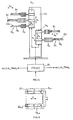
- Fig. 14 there is schematically shown a robot 11 which may be applied within the vacuum chamber of the transport arrangement TA as of figure 12 and 13 .
- Fig. 14 there is provided within the vacuum chamber of the transport arrangements (not shown) a stationary central support post 13.
- a first sliding arrangement 14 a which is vertically slideable - va - in controlled driven manner.
- a number of single substrate supporting member 15 a mounted to sliding arrangement 14 a there is provided a number of single substrate supporting member 15 a , as shown e.g. three. They project horizontally and are vertically mounted distant form each other and, in one preferred embodiment, with a controllably variable pitch distance p a .
- the pitch distance p a in this preferred embodiment may be controllably varied, e.g. to accommodate for substrate handling openings at the LLA and/or PMA with different vertical pitch distances.
- Each of the supporting members 15 a may be expanded and retracted horizontally - h -, driven by telescopic drives, as shown within encapsulations 17 a .
- the supporting members 15 a have supports with supporting pins 20 whereupon the substrates 3a to be processed in LLPT 1a are disposed during horizontal and vertical transport.
- a second sliding arrangement 14 b opposite sliding arrangement 14 a along post 13, which is construed with supporting members 15 b , supports 19 b supporting pins 20 b , encapsulates 17 b very much like the arrangement mounted on slide 14 a whereby, as shown, the number of supporting members 15 b which do handle substrates 3b with respect to LLPT 1b as of figure 12 or 13 needs not to be equal with the number of members 15 a for serving substrate 3a to be processed by a LLPT 1a.
- the horizontally movable supports 9a and 9b are construed in a forklike manner as shown in Fig. 15 .
- Fig. 15 shows a respective substrate 3a,b residing on the support 19 a,b and being thereby deposited on support pins 21 in a LLA or PMA.
- an apparatus with two distinct loadlock- and processing towers LLPT 1a and 1b which each provide for the complete set of modules to perform substrate processing inclusive feeding such substrate from surrounding atmosphere AT to the vacuum processing and from vacuum processing back to surrounding atmosphere.
- the robot 9ab within the transport arrangements TA 2ab needs not perform any rotational movement.
- Substrate transport is realised merely by horizontal - h - and vertical - v - substrate movement.
- a controlling unit 21 is provided for controlling the horizontal transport movements h a,b , the vertical transport movements v a,b with respect to their extent, timing of respective horizontal and vertical transport cycles as well as, if necessary, pitch distance pa of the respective support arrangements.
- a control unit 21 is preferably realised as a free programmable unit so that in dependency of an intended processing especially timing of the transport cycles may flexibly be adapted.
- Such a controlling unit 21 preferably also controls processing and loadlock cycles as schematically shown in Fig. 14 with the control connections to LLA ab and PMA ab .
- the transport robot within transport arrangement TA 9ab in fact provides only for one single up/down moving facility.
- such robot comprises a drawerlike member 25 which is controllably drivable in vertical direction v up and down guide 27.
- a slide 29 which has a frame or forklike shape and which may be horizontal driven into a respective module of the loadlock - or process module arrangement.
- this embodiment of a transport robot provides the possibility to propel the slide 29 to the left or to the right hand side of the guide members 27.
- the apparatus according to the present invention in its most preferred embodiments as of Figs. 10 and 12 does not necessitate any rotational movement about the vertical axis of a robot handling the substrates.
- the embodiment as of Fig. 12 may be called I-type due to its I-shaped footprint.
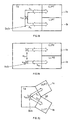
- FIGs. 17 , 18, and 19 further preferred embodiments of the apparatus according to the present invention are schematically shown representations in analogy to that of Fig. 13 . These embodiments do also not necessitate any rotational movement of a robot within the transport arrangement TA, about a vertical axis, so as to serve the openings of the LLPT's.
- Fig. 17 to 19 instead of construing the apparatus in an I-type configuration as of Figs. 12 and 13 it is designed as a U-type apparatus.
- the two LLPT's 1a and 1b are provided in a side by side position.
- two robots 9a and 9b are installed, each serving the modules of one of the LLPT 1a,1b via the respective openings.
- Each of the robots 9a,9b provides for a vertical up and down movement v a ,v b in a controllably driven manner.
- Each of the robots 9a,9b further provides for horizontal forth and back movement h a and h b towards and into or from the modules of the respective LLPT 1a,1b.
- the robots 9a and 9b may e.g. be principally conceived according to the robot shown in Fig. 14 with support members 15 a and 15 b not pointing from each other but being provided on one side of support 13 and in parallelism.
- the movements of the two robots 9a and 9b may be independently controlled preferably by means of a freely reprogrammable control unit (not shown). If a time-synchronous processing shall be established at the two LLPT 1a,1b, either the two independently controllable robots 9a and 9b are synchronously operated, or there is provided a single robot which serves simultaneously both LLPT 1a,1b.
- FIG. 18 Such an embodiment is shown in Fig. 18 again schematically and in a representation in analogy to that of Fig. 17 .
- one single robot 9ab which provides combined common vertical transport movement v ab of substrates into alignment with openings at the LLPT 1a and 1b
- the horizontal movements h a ,h b are either synchronised, or are controlled specifically for each LLPTM.
- FIG. 19 A third embodiment of U-shaped concept is shown in Fig. 19 .
- the one robot 9ab serves by vertical transport movement v ab and horizontal transport movement h ab both LLPT's 1a and 1b. To do so the robot 9ab performs a horizontal movement w ab as shown.
- a variant is shown in Fig. 20 , as an Y-type concept.
- the two LLPT's 1a and 1b are arranged at the transport arrangement TA so as to define an angle ⁇ .
- the robot concept is principally the same as shown in Fig. 18 .
- the single robot 9ab serves the modules of both angularly displaced LLPT 1a and 1b. Thereby, such robot may be realised very similar to that shown in Fig. 14 , thereby providing the supporting members not opposite each others but at the desired angle ⁇ about the central axis of post 13.
- a further mode of realising the robot within transport arrangement TA is shown in Fig. 21 .
- the robot 9ab is conceived to rotate about the central axis by at least the angle of ⁇ so as to serve the modules of both angularly displaced LLPT's 1a,1b.
- LLPT's allows flexible full parallel processing of different or equal multi-step processes.
- a transport robot 9 rot which is rotatable about a central axis so as to serve more than two as shown e.g. for LLPT's mounted circularly around the transport arrangement TA.
- more preferred embodiments of the apparatus according to the present invention are the two LLPT-structures of I- or U- or possibly Y-type as of Figs. 17 to 21 .
- Fig. 23 there is shown a today's preferred apparatus as used in the frame of the present invention. It is conceived according to the concept of Fig. 10 . It comprises one single LLPT which consists, from top to bottom, of a two-substrate batch processing module BPM 1 followed by a two-substrate batch input and output load lock module BLL io , followed by a second two-substrate batch processing module BPM 2 .
- the loadlock module BLL io is subdivided into a first input loadlock compartment C i , followed by a first output loadlock compartment C o , followed by a second input loadlock compartment C i and finally a second output loadlock compartment C o .
- the respective openings 33 which establish communication between BPM 1 , BLL io , BPM 2 and a transport arrangement TA, are provided with respectively controlled valves 35.
- a robot 39 which is drivingly moveable in a controlled manner in horizontal direction h and comprises a two-substrate batch transport member 41 with an upper and with a lower substrate transport fork 43 U and 43 1 .
- the overall arrangement of the two horizontal transport members 41 is drivingly moveable vertically in a controlled manner.
- the pitch between the upper substrate carrier fork 43 u and a lower substrate carrier fork 43 1 is selected to be in agreement with the pitch between the openings at each of the batch processing modules and the batch loadlock module.
- Such an apparatus is most suited to be used for processing large substrates of at least 1m 2 , preferably of at least 2m 2 , even of at least 4m 2 as for solar panel, TFT or plasma display panel manufacturing.
- process modules of the present invention may be separated from the transport chamber by valves, they can operate independently from each other if required.
Landscapes
- Engineering & Computer Science (AREA)
- Chemical & Material Sciences (AREA)
- Mechanical Engineering (AREA)
- General Engineering & Computer Science (AREA)
- Chemical Kinetics & Catalysis (AREA)
- Materials Engineering (AREA)
- Metallurgy (AREA)
- Organic Chemistry (AREA)
- General Chemical & Material Sciences (AREA)
- Container, Conveyance, Adherence, Positioning, Of Wafer (AREA)
- Physical Vapour Deposition (AREA)
Claims (19)
- Vorrichtung zur Vakuumbehandlung von sich zweidimensional erstreckenden Substrate, umfassend(a) eine Vakuumtransportkammer (TA) mit einer Transportroboter-Anordnung (9ab);(b) eine Verarbeitungseinrichtung (PMAa) mit mindestens einer Verarbeitungsstation, die durch mindestens eine Werkstückdurchtrittsöffnung (Os) mit der Vakuumtransportkammer (TA) kommuniziert;(c) eine Ladeschleusenanordnung (LLAa), die durch zumindest eine Werkstückdurchtrittsöffnung (Os) mit der Vakuumtransportkammer (TA) und durch mindestens eine weitere Werkstückdurchtrittsöffnung (Os) mit einer Atmosphäre (AT) außerhalb der Vakuumtransportkammer (TA) und der Verarbeitungseinrichtung (PMAa) kommuniziert;(d1) einen Ladeschleusen- und Verarbeitungsturm (1, LLPT1) der durch die Verarbeitungseinrichtung (PMAa) und die Ladeschleusenanordnung (LLAa), die vertikal aufeinander angeordnet sind, ausgebildet ist;dadurch gekennzeichnet, dass die Vorrichtung mindestens zwei der Ladeschleusen- und Verarbeitungstürme (1a, 1b; LLPT1a, LLPT1b) umfasst.
- Vorrichtung gemäß Anspruch 1, wobei der Transportroboter (9ab) mindestens einen im wesentlichen horizontalen Substratträger (15a) für mindestens ein Substrat (3b) umfasst, wobei der Substratträger angetrieben und steuerbar sowohl in Vertikalrichtung (v) als auch in Horizontalrichtung (h) in Ausrichtung mit den Öffnungen (Os) und in den und aus den mindestens zwei Ladeschleusen- und Verarbeitungstürmen (1a, 1b; LLPT1a, LLPT1b) bewegbar ist.
- Vorrichtung nach Anspruch 2, wobei der Substratträger zusätzlich in einer steuerbar angetriebenen Weise um eine vertikale Achse (ϕ) drehbar ist.
- Vorrichtung nach Anspruch 3, wobei die Drehbewegung auf maximal 180° begrenzt ist.
- Vorrichtung nach Anspruch 4, wobei die Drehbewegung auf maximal 45° begrenzt ist.
- Vorrichtung nach Anspruch 1, wobei der Transportroboter mindestens einen horizontalen Substratträger (15a) für mindestens ein Substrat (3a) umfasst, wobei der Substratträger ausschließlich in vertikaler (v) und in horizontaler (h) Richtung angetrieben wird, auf eine entsprechend gesteuerte Weise.
- Vorrichtung nach Anspruch 1, wobei mindestens eine der Verarbeitungsanordnungen (PMAa, PMAb) mindestens ein Modul zur Verarbeitung von Substratbeschickung aufweist.
- Vorrichtung nach Anspruch 1, wobei mindestens eine der Verarbeitungsanordnungen (PMAa, PMAb) mindestens ein einzelnes Substratverarbeitungsmodul umfasst.
- Vorrichtung nach Anspruch 1, wobei zumindest eine der Ladeschleusenanordnungen (LLAa, LLAb) eine Eingabe-/ Ausgabe-Ladeschleusenanordnung umfasst.
- Vorrichtung nach Anspruch 9, wobei die Eingabe-/ Ausgabe-Ladeschleusenanordnung mindestens eine einzelne Substrateingabeschleusenkammer umfasst.
- Vorrichtung nach Anspruch 9, wobei die Eingabe-/ Ausgabe-Ladeschleusenanordnung mindestens eine einzelne Substratausgabeschleusenkammer umfasst
- Vorrichtung nach Anspruch 9, wobei die Eingabe-/ Ausgabe-Ladeschleusenanordnung wenigstens eine Substratbeschickungseingabeschleusenkammer, eine Substratbeschickungsausgabeschleusenkammer und eine Eingabe-/ Ausgabe-Substratbeschickungsschleusenkammer umfasst.
- Vorrichtung nach Anspruch 1, wobei einer der Ladeschleusen- und Verarbeitungstürme eine Eingabe- (LLi) und eine Ausgabeschleusenanordnung (LLo) umfasst.
- Vorrichtung nach Anspruch 1, wobei ausschließlich zwei der Ladeschleusen- und Verarbeitungstürme (1a, 1b) auf gegenüberliegenden Seiten der Transportvakuumkammer (TA) angeordnet sind und dabei einander zugewandt sind.
- Vorrichtung nach Anspruch 1, wobei ausschließlich zwei der Ladeschleusen- und Verarbeitungstürme (1a, 1b) vorgesehen sind, eine neben der anderen angeordnet auf einer Seite der VakuumTransportkammer (TA), dem Turm und der Vakuumtransportkammer und dabei gleichzeitig für eine U-förmige Grundfläche definieren.
- Vorrichtung nach Anspruch 1, wobei ausschließlich zwei der Ladeschleusen- und Verarbeitungstürme (1a, 1b) mit der Vakuumtransportkammer (TA) ausgestattet sind und dabei gleichzeitig eine Y-förmige Grundfläche definieren.
- Vorrichtung nach Anspruch 1, wobei das Substrat eine Verlängerung von mindestens 1m2, vorzugsweise von mindestens 2m2 und noch bevorzugter von mindestens 4m2 hat.
- Vorrichtung nach Anspruch 1, wobei die Ladeschleusenanordnung mindestens eine Heiz- und eine Kühlvorrichtung für mindestens ein Substrat aufweist.
- Verfahren zur Herstellung von sich zweidimensional erstreckenden vakuumbehandelten Substraten, umfassend die Schritte● Durchführen einer ersten Verarbeitungssequenz nach einer ersten Reihe von Substraten (3a) durch eine Ladeschleusenanordnung (LLAa) und eine Verarbeitungseinrichtung (PMAa) eines ersten Ladeschleusen- und Verarbeitungsturms (1a; LLPT1a), wobei die Ladeschleusenanordnung (LLAa) und die Verarbeitungseinrichtung (PMAa) vertikal gestapelt angeordnet sind;● Durchführen einer zweiten Verarbeitungssequenz nach einer zweiten Reihe von Substraten (3b) durch eine Ladeschleusenanordnung (LLAb) und eine Verarbeitungseinrichtung (PMA) eines zweiten Ladeschleusen- und Verarbeitungsturms (1b; LLPT1b), wobei die Ladeschleusenanordnung (LLAb) und die Verarbeitungseinrichtung (LLPT1b) vertikal gestapelt angeordnet sind.● die erste Reihe und die zweite Reihe von Substraten sind unterschiedliche Reihen;● Durchführen eines Transport der unterschiedlichen Substratreihen im Bezug auf den ersten (1a; LLPT1a) und im Bezug auf den zweiten (1b; LLPT1b) Ladeschleusen- und Verarbeitungstürme unabhängig voneinander, horizontal und vertikal durch einen Roboter (9ab) einer Transportvorrichtung die bei beiden Verarbeitungstürmen vorhanden ist.
Applications Claiming Priority (3)
| Application Number | Priority Date | Filing Date | Title |
|---|---|---|---|
| US42669702P | 2002-11-15 | 2002-11-15 | |
| US426697P | 2002-11-15 | ||
| PCT/CH2003/000742 WO2004046416A1 (en) | 2002-11-15 | 2003-11-12 | Apparatus for vacuum treating two dimensionally extended substrates and method for manufacturing such substrates |
Publications (2)
| Publication Number | Publication Date |
|---|---|
| EP1560944A1 EP1560944A1 (de) | 2005-08-10 |
| EP1560944B1 true EP1560944B1 (de) | 2014-03-05 |
Family
ID=32326404
Family Applications (1)
| Application Number | Title | Priority Date | Filing Date |
|---|---|---|---|
| EP03769143.3A Expired - Lifetime EP1560944B1 (de) | 2002-11-15 | 2003-11-12 | Vorrichtung zur vakuumbehandlung von zweidimensional verlängerten substraten und verfahren zur herstellung derartiger substrate |
Country Status (8)
| Country | Link |
|---|---|
| US (2) | US7244086B2 (de) |
| EP (1) | EP1560944B1 (de) |
| JP (1) | JP2006506818A (de) |
| KR (1) | KR101120497B1 (de) |
| CN (1) | CN1711369B (de) |
| AU (1) | AU2003277790A1 (de) |
| TW (1) | TW200414297A (de) |
| WO (1) | WO2004046416A1 (de) |
Families Citing this family (25)
| Publication number | Priority date | Publication date | Assignee | Title |
|---|---|---|---|---|
| JPH0936198A (ja) * | 1995-07-19 | 1997-02-07 | Hitachi Ltd | 真空処理装置およびそれを用いた半導体製造ライン |
| NL1028907C2 (nl) * | 2005-04-29 | 2006-10-31 | Fico Bv | Werkwijze en inrichting voor het aanvoeren en het afvoeren van dragers met elektronische componenten. |
| KR100737716B1 (ko) * | 2005-05-26 | 2007-07-10 | 주식회사 에이디피엔지니어링 | 플라즈마 처리장치 |
| US7628574B2 (en) * | 2006-03-28 | 2009-12-08 | Arcus Technology, Inc. | Apparatus and method for processing substrates using one or more vacuum transfer chamber units |
| ITBS20060208A1 (it) * | 2006-11-30 | 2008-06-01 | Estral Spa | Metodo ed impianto per il trattamento termico di elementi metallici |
| JP5795162B2 (ja) * | 2007-05-18 | 2015-10-14 | ブルックス オートメーション インコーポレイテッド | ロードロック高速排気および通気 |
| US10541157B2 (en) | 2007-05-18 | 2020-01-21 | Brooks Automation, Inc. | Load lock fast pump vent |
| US20100047954A1 (en) * | 2007-08-31 | 2010-02-25 | Su Tzay-Fa Jeff | Photovoltaic production line |
| US8225496B2 (en) | 2007-08-31 | 2012-07-24 | Applied Materials, Inc. | Automated integrated solar cell production line composed of a plurality of automated modules and tools including an autoclave for curing solar devices that have been laminated |
| KR101046520B1 (ko) | 2007-09-07 | 2011-07-04 | 어플라이드 머티어리얼스, 인코포레이티드 | 내부 챔버 상의 부산물 막 증착을 제어하기 위한 pecvd 시스템에서의 소스 가스 흐름 경로 제어 |
| US20090188603A1 (en) * | 2008-01-25 | 2009-07-30 | Applied Materials, Inc. | Method and apparatus for controlling laminator temperature on a solar cell |
| JP5139253B2 (ja) * | 2008-12-18 | 2013-02-06 | 東京エレクトロン株式会社 | 真空処理装置及び真空搬送装置 |
| US20100162954A1 (en) * | 2008-12-31 | 2010-07-01 | Lawrence Chung-Lai Lei | Integrated facility and process chamber for substrate processing |
| US8367565B2 (en) * | 2008-12-31 | 2013-02-05 | Archers Inc. | Methods and systems of transferring, docking and processing substrates |
| US20100162955A1 (en) * | 2008-12-31 | 2010-07-01 | Lawrence Chung-Lai Lei | Systems and methods for substrate processing |
| US8110511B2 (en) * | 2009-01-03 | 2012-02-07 | Archers Inc. | Methods and systems of transferring a substrate to minimize heat loss |
| US7897525B2 (en) * | 2008-12-31 | 2011-03-01 | Archers Inc. | Methods and systems of transferring, docking and processing substrates |
| JP5037551B2 (ja) * | 2009-03-24 | 2012-09-26 | 東京エレクトロン株式会社 | 基板交換機構及び基板交換方法 |
| WO2012017653A1 (ja) * | 2010-08-06 | 2012-02-09 | 東京エレクトロン株式会社 | 基板処理システム、搬送モジュール、基板処理方法及び半導体素子の製造方法 |
| US20130340939A1 (en) * | 2012-06-21 | 2013-12-26 | Tel Solar Ag | System for substrate handling and processing |
| JP6902379B2 (ja) * | 2017-03-31 | 2021-07-14 | 東京エレクトロン株式会社 | 処理システム |
| KR102837677B1 (ko) * | 2018-05-15 | 2025-07-24 | 에바텍 아크티엔게젤샤프트 | 기판 진공 처리 장치 및 기판을 진공 처리하는 방법 |
| DE102018216878A1 (de) * | 2018-10-01 | 2020-04-02 | centrotherm international AG | Transporteinheit für paralleles Einfahren oder Ausfahren von Substratträgern, in parallele Prozessrohre und Verfahren zum gleichzeitigen Beladen von parallelen, horizontal beabstandeten Prozessrohren |
| US11965682B2 (en) | 2020-12-16 | 2024-04-23 | Samsung Electronics Co., Ltd. | Air conditioner |
| US20240087924A1 (en) * | 2022-09-12 | 2024-03-14 | Hine Automation, Llc | Multi-chamber Configuration |
Family Cites Families (35)
| Publication number | Priority date | Publication date | Assignee | Title |
|---|---|---|---|---|
| US2933207A (en) * | 1957-06-19 | 1960-04-19 | Structural Clay Products Res F | Unit stacking apparatus |
| US5288852A (en) * | 1984-03-06 | 1994-02-22 | Dainippon Pharmaceutical Co., Ltd. | Human tumor necrosis factor polypeptides |
| US4951601A (en) * | 1986-12-19 | 1990-08-28 | Applied Materials, Inc. | Multi-chamber integrated process system |
| WO1991004213A1 (en) * | 1989-09-12 | 1991-04-04 | Rapro Technology, Inc. | Automated wafer transport system |
| CA2112682C (en) | 1991-07-03 | 2002-04-23 | Michael A. Teitel | Virtual image display device |
| US5275709A (en) | 1991-11-07 | 1994-01-04 | Leybold Aktiengesellschaft | Apparatus for coating substrates, preferably flat, more or less plate-like substrates |
| ES2090893T3 (es) | 1993-01-28 | 1996-10-16 | Applied Materials Inc | Aparato de tratamiento en vacio que tiene una capacidad de produccion mejorada. |
| US6296735B1 (en) | 1993-05-03 | 2001-10-02 | Unaxis Balzers Aktiengesellschaft | Plasma treatment apparatus and method for operation same |
| CH687986A5 (de) | 1993-05-03 | 1997-04-15 | Balzers Hochvakuum | Plasmabehandlungsanlage und Verfahren zu deren Betrieb. |
| CH687987A5 (de) | 1993-05-03 | 1997-04-15 | Balzers Hochvakuum | Verfahren zur Erhoehung der Beschichtungsrate in einem Plasmaentladungsraum und Plasmakammer. |
| KR100244041B1 (ko) * | 1995-08-05 | 2000-02-01 | 엔도 마코토 | 기판처리장치 |
| US5820366A (en) | 1996-07-10 | 1998-10-13 | Eaton Corporation | Dual vertical thermal processing furnace |
| KR100234539B1 (ko) | 1996-12-24 | 1999-12-15 | 윤종용 | 반도체장치 제조용 식각 장치 |
| US6099643A (en) * | 1996-12-26 | 2000-08-08 | Dainippon Screen Mfg. Co., Ltd. | Apparatus for processing a substrate providing an efficient arrangement and atmospheric isolation of chemical treatment section |
| US6391377B1 (en) | 1997-07-08 | 2002-05-21 | Unaxis Balzers Aktiengesellschaft | Process for vacuum treating workpieces, and corresponding process equipment |
| TW589391B (en) | 1997-07-08 | 2004-06-01 | Unaxis Trading Ag | Process for vacuum treating workpieces, and corresponding process equipment |
| JPH11129184A (ja) * | 1997-09-01 | 1999-05-18 | Dainippon Screen Mfg Co Ltd | 基板処理装置および基板搬入搬出装置 |
| US6053687A (en) | 1997-09-05 | 2000-04-25 | Applied Materials, Inc. | Cost effective modular-linear wafer processing |
| KR100265287B1 (ko) | 1998-04-21 | 2000-10-02 | 윤종용 | 반도체소자 제조용 식각설비의 멀티챔버 시스템 |
| JP2965038B1 (ja) * | 1998-09-21 | 1999-10-18 | 日新電機株式会社 | 真空処理装置 |
| JP2000195925A (ja) * | 1998-12-28 | 2000-07-14 | Anelva Corp | 基板処理装置 |
| JP3455458B2 (ja) * | 1999-02-01 | 2003-10-14 | 東京エレクトロン株式会社 | 塗布、現像装置及び塗布現像処理における基板再生システム |
| US6610150B1 (en) * | 1999-04-02 | 2003-08-26 | Asml Us, Inc. | Semiconductor wafer processing system with vertically-stacked process chambers and single-axis dual-wafer transfer system |
| JP3442686B2 (ja) * | 1999-06-01 | 2003-09-02 | 東京エレクトロン株式会社 | 基板処理装置 |
| US6318945B1 (en) * | 1999-07-28 | 2001-11-20 | Brooks Automation, Inc. | Substrate processing apparatus with vertically stacked load lock and substrate transport robot |
| US6402400B1 (en) * | 1999-10-06 | 2002-06-11 | Tokyo Electron Limited | Substrate processing apparatus |
| US6402401B1 (en) * | 1999-10-19 | 2002-06-11 | Tokyo Electron Limited | Substrate processing apparatus and substrate processing method |
| US6296375B1 (en) | 2000-01-05 | 2001-10-02 | Maxlite-Sk America, Inc. | Compact fluorescent lamp having a detachable translucent cover |
| SG94851A1 (en) * | 2000-07-12 | 2003-03-18 | Tokyo Electron Ltd | Substrate processing apparatus and substrate processing method |
| JP4004248B2 (ja) * | 2000-09-01 | 2007-11-07 | 大日本スクリーン製造株式会社 | 基板処理装置および基板検査方法 |
| KR100398877B1 (ko) * | 2001-05-09 | 2003-09-19 | 삼성전자주식회사 | 현상기 소음 및 진동방지구조를 갖는 화상형성장치 |
| JP2003077974A (ja) * | 2001-08-31 | 2003-03-14 | Hitachi Kokusai Electric Inc | 基板処理装置および半導体装置の製造方法 |
| US7351291B2 (en) * | 2002-02-20 | 2008-04-01 | Tokyo Electron Limited | Semiconductor processing system |
| US7335277B2 (en) * | 2003-09-08 | 2008-02-26 | Hitachi High-Technologies Corporation | Vacuum processing apparatus |
| JP4246654B2 (ja) * | 2004-03-08 | 2009-04-02 | 株式会社日立ハイテクノロジーズ | 真空処理装置 |
-
2003
- 2003-11-12 AU AU2003277790A patent/AU2003277790A1/en not_active Abandoned
- 2003-11-12 EP EP03769143.3A patent/EP1560944B1/de not_active Expired - Lifetime
- 2003-11-12 JP JP2004552336A patent/JP2006506818A/ja not_active Withdrawn
- 2003-11-12 WO PCT/CH2003/000742 patent/WO2004046416A1/en not_active Ceased
- 2003-11-12 CN CN2003801032739A patent/CN1711369B/zh not_active Expired - Fee Related
- 2003-11-12 KR KR1020057008231A patent/KR101120497B1/ko not_active Expired - Fee Related
- 2003-11-14 TW TW092131975A patent/TW200414297A/zh unknown
- 2003-11-14 US US10/713,339 patent/US7244086B2/en not_active Expired - Fee Related
-
2007
- 2007-05-30 US US11/755,423 patent/US20080038095A1/en not_active Abandoned
Also Published As
| Publication number | Publication date |
|---|---|
| EP1560944A1 (de) | 2005-08-10 |
| AU2003277790A1 (en) | 2004-06-15 |
| US20040115032A1 (en) | 2004-06-17 |
| CN1711369A (zh) | 2005-12-21 |
| JP2006506818A (ja) | 2006-02-23 |
| TW200414297A (en) | 2004-08-01 |
| KR101120497B1 (ko) | 2012-02-29 |
| CN1711369B (zh) | 2011-07-13 |
| WO2004046416A1 (en) | 2004-06-03 |
| KR20050086451A (ko) | 2005-08-30 |
| US7244086B2 (en) | 2007-07-17 |
| US20080038095A1 (en) | 2008-02-14 |
Similar Documents
| Publication | Publication Date | Title |
|---|---|---|
| US7244086B2 (en) | Apparatus for vacuum treating two dimensionally extended substrates and method for manufacturing such substrates | |
| EP2207909B1 (de) | Verfahren zur herstellung von werkstücken und gerät | |
| US6183615B1 (en) | Transport system for wafer processing line | |
| US6846149B2 (en) | Semiconductor wafer processing system with vertically-stacked process chambers and single-axis dual-wafer transfer system | |
| TWI553765B (zh) | 真空處理設備 | |
| US7628574B2 (en) | Apparatus and method for processing substrates using one or more vacuum transfer chamber units | |
| US20150243490A1 (en) | Substrate processing apparatus and substrate processing method | |
| CN102246286A (zh) | 真空处理装置、真空运送装置 | |
| TW201145443A (en) | Substrate load and unload mechanisms for high throughput | |
| US9048271B2 (en) | Modular semiconductor processing system | |
| US20160293459A1 (en) | Apparatus for processing sustrate and semiconductor fabrication line including the same | |
| US6177129B1 (en) | Process for handling workpieces and apparatus therefor | |
| KR20050042191A (ko) | 대면적 기판 처리 시스템 | |
| KR20180066192A (ko) | 진공 처리 장치 | |
| JP4838357B2 (ja) | 真空搬送装置 | |
| KR102058985B1 (ko) | 로드 스테이션 | |
| US20010051081A1 (en) | Processes for vacuum treating workpieces, and corresponding process equipment | |
| JP6833610B2 (ja) | 有機材料用の蒸発源、有機材料用の蒸発源を有する装置、有機材料用の蒸発源を含む蒸発堆積装置を有するシステム、及び有機材料用の蒸発源を操作するための方法 | |
| CN113451186B (zh) | 传送机器人及包括此的基板处理系统 | |
| TW202329303A (zh) | 晶圓處理裝置、晶圓處理系統及控制方法 | |
| EP3706162A1 (de) | Substrat-unterbringungsvorrichtung | |
| KR101413243B1 (ko) | 웨이퍼 전달모듈 및 이를 구비한 박막 증착 시스템 | |
| WO2008068859A1 (ja) | 搬送装置 |
Legal Events
| Date | Code | Title | Description |
|---|---|---|---|
| PUAI | Public reference made under article 153(3) epc to a published international application that has entered the european phase |
Free format text: ORIGINAL CODE: 0009012 |
|
| 17P | Request for examination filed |
Effective date: 20050415 |
|
| AK | Designated contracting states |
Kind code of ref document: A1 Designated state(s): AT BE BG CH CY CZ DE DK EE ES FI FR GB GR HU IE IT LI LU MC NL PT RO SE SI SK TR |
|
| AX | Request for extension of the european patent |
Extension state: AL LT LV MK |
|
| DAX | Request for extension of the european patent (deleted) | ||
| 17Q | First examination report despatched |
Effective date: 20070919 |
|
| RAP1 | Party data changed (applicant data changed or rights of an application transferred) |
Owner name: OC OERLIKON BALZERS AG |
|
| RAP1 | Party data changed (applicant data changed or rights of an application transferred) |
Owner name: OERLIKON SOLAR AG, TRUEBBACH |
|
| RAP1 | Party data changed (applicant data changed or rights of an application transferred) |
Owner name: TEL SOLAR AG |
|
| GRAP | Despatch of communication of intention to grant a patent |
Free format text: ORIGINAL CODE: EPIDOSNIGR1 |
|
| INTG | Intention to grant announced |
Effective date: 20130918 |
|
| GRAS | Grant fee paid |
Free format text: ORIGINAL CODE: EPIDOSNIGR3 |
|
| GRAA | (expected) grant |
Free format text: ORIGINAL CODE: 0009210 |
|
| AK | Designated contracting states |
Kind code of ref document: B1 Designated state(s): AT BE BG CH CY CZ DE DK EE ES FI FR GB GR HU IE IT LI LU MC NL PT RO SE SI SK TR |
|
| REG | Reference to a national code |
Ref country code: GB Ref legal event code: FG4D |
|
| REG | Reference to a national code |
Ref country code: CH Ref legal event code: EP |
|
| REG | Reference to a national code |
Ref country code: AT Ref legal event code: REF Ref document number: 654952 Country of ref document: AT Kind code of ref document: T Effective date: 20140315 |
|
| REG | Reference to a national code |
Ref country code: IE Ref legal event code: FG4D |
|
| REG | Reference to a national code |
Ref country code: DE Ref legal event code: R096 Ref document number: 60345803 Country of ref document: DE Effective date: 20140417 |
|
| REG | Reference to a national code |
Ref country code: AT Ref legal event code: MK05 Ref document number: 654952 Country of ref document: AT Kind code of ref document: T Effective date: 20140305 |
|
| REG | Reference to a national code |
Ref country code: NL Ref legal event code: VDEP Effective date: 20140305 |
|
| PG25 | Lapsed in a contracting state [announced via postgrant information from national office to epo] |
Ref country code: AT Free format text: LAPSE BECAUSE OF FAILURE TO SUBMIT A TRANSLATION OF THE DESCRIPTION OR TO PAY THE FEE WITHIN THE PRESCRIBED TIME-LIMIT Effective date: 20140305 Ref country code: FI Free format text: LAPSE BECAUSE OF FAILURE TO SUBMIT A TRANSLATION OF THE DESCRIPTION OR TO PAY THE FEE WITHIN THE PRESCRIBED TIME-LIMIT Effective date: 20140305 Ref country code: CY Free format text: LAPSE BECAUSE OF FAILURE TO SUBMIT A TRANSLATION OF THE DESCRIPTION OR TO PAY THE FEE WITHIN THE PRESCRIBED TIME-LIMIT Effective date: 20140305 Ref country code: SE Free format text: LAPSE BECAUSE OF FAILURE TO SUBMIT A TRANSLATION OF THE DESCRIPTION OR TO PAY THE FEE WITHIN THE PRESCRIBED TIME-LIMIT Effective date: 20140305 |
|
| PG25 | Lapsed in a contracting state [announced via postgrant information from national office to epo] |
Ref country code: BE Free format text: LAPSE BECAUSE OF FAILURE TO SUBMIT A TRANSLATION OF THE DESCRIPTION OR TO PAY THE FEE WITHIN THE PRESCRIBED TIME-LIMIT Effective date: 20140305 Ref country code: BG Free format text: LAPSE BECAUSE OF FAILURE TO SUBMIT A TRANSLATION OF THE DESCRIPTION OR TO PAY THE FEE WITHIN THE PRESCRIBED TIME-LIMIT Effective date: 20140605 Ref country code: NL Free format text: LAPSE BECAUSE OF FAILURE TO SUBMIT A TRANSLATION OF THE DESCRIPTION OR TO PAY THE FEE WITHIN THE PRESCRIBED TIME-LIMIT Effective date: 20140305 Ref country code: CZ Free format text: LAPSE BECAUSE OF FAILURE TO SUBMIT A TRANSLATION OF THE DESCRIPTION OR TO PAY THE FEE WITHIN THE PRESCRIBED TIME-LIMIT Effective date: 20140305 Ref country code: RO Free format text: LAPSE BECAUSE OF FAILURE TO SUBMIT A TRANSLATION OF THE DESCRIPTION OR TO PAY THE FEE WITHIN THE PRESCRIBED TIME-LIMIT Effective date: 20140305 Ref country code: EE Free format text: LAPSE BECAUSE OF FAILURE TO SUBMIT A TRANSLATION OF THE DESCRIPTION OR TO PAY THE FEE WITHIN THE PRESCRIBED TIME-LIMIT Effective date: 20140305 |
|
| PG25 | Lapsed in a contracting state [announced via postgrant information from national office to epo] |
Ref country code: SK Free format text: LAPSE BECAUSE OF FAILURE TO SUBMIT A TRANSLATION OF THE DESCRIPTION OR TO PAY THE FEE WITHIN THE PRESCRIBED TIME-LIMIT Effective date: 20140305 Ref country code: ES Free format text: LAPSE BECAUSE OF FAILURE TO SUBMIT A TRANSLATION OF THE DESCRIPTION OR TO PAY THE FEE WITHIN THE PRESCRIBED TIME-LIMIT Effective date: 20140305 |
|
| REG | Reference to a national code |
Ref country code: DE Ref legal event code: R097 Ref document number: 60345803 Country of ref document: DE |
|
| PG25 | Lapsed in a contracting state [announced via postgrant information from national office to epo] |
Ref country code: PT Free format text: LAPSE BECAUSE OF FAILURE TO SUBMIT A TRANSLATION OF THE DESCRIPTION OR TO PAY THE FEE WITHIN THE PRESCRIBED TIME-LIMIT Effective date: 20140707 |
|
| PLBE | No opposition filed within time limit |
Free format text: ORIGINAL CODE: 0009261 |
|
| STAA | Information on the status of an ep patent application or granted ep patent |
Free format text: STATUS: NO OPPOSITION FILED WITHIN TIME LIMIT |
|
| PG25 | Lapsed in a contracting state [announced via postgrant information from national office to epo] |
Ref country code: DK Free format text: LAPSE BECAUSE OF FAILURE TO SUBMIT A TRANSLATION OF THE DESCRIPTION OR TO PAY THE FEE WITHIN THE PRESCRIBED TIME-LIMIT Effective date: 20140305 |
|
| 26N | No opposition filed |
Effective date: 20141208 |
|
| REG | Reference to a national code |
Ref country code: DE Ref legal event code: R097 Ref document number: 60345803 Country of ref document: DE Effective date: 20141208 |
|
| PG25 | Lapsed in a contracting state [announced via postgrant information from national office to epo] |
Ref country code: IT Free format text: LAPSE BECAUSE OF FAILURE TO SUBMIT A TRANSLATION OF THE DESCRIPTION OR TO PAY THE FEE WITHIN THE PRESCRIBED TIME-LIMIT Effective date: 20140305 |
|
| PG25 | Lapsed in a contracting state [announced via postgrant information from national office to epo] |
Ref country code: SI Free format text: LAPSE BECAUSE OF FAILURE TO SUBMIT A TRANSLATION OF THE DESCRIPTION OR TO PAY THE FEE WITHIN THE PRESCRIBED TIME-LIMIT Effective date: 20140305 |
|
| PG25 | Lapsed in a contracting state [announced via postgrant information from national office to epo] |
Ref country code: MC Free format text: LAPSE BECAUSE OF FAILURE TO SUBMIT A TRANSLATION OF THE DESCRIPTION OR TO PAY THE FEE WITHIN THE PRESCRIBED TIME-LIMIT Effective date: 20140305 Ref country code: LU Free format text: LAPSE BECAUSE OF FAILURE TO SUBMIT A TRANSLATION OF THE DESCRIPTION OR TO PAY THE FEE WITHIN THE PRESCRIBED TIME-LIMIT Effective date: 20141112 |
|
| REG | Reference to a national code |
Ref country code: CH Ref legal event code: PL |
|
| GBPC | Gb: european patent ceased through non-payment of renewal fee |
Effective date: 20141112 |
|
| PG25 | Lapsed in a contracting state [announced via postgrant information from national office to epo] |
Ref country code: LI Free format text: LAPSE BECAUSE OF NON-PAYMENT OF DUE FEES Effective date: 20141130 Ref country code: CH Free format text: LAPSE BECAUSE OF NON-PAYMENT OF DUE FEES Effective date: 20141130 |
|
| REG | Reference to a national code |
Ref country code: IE Ref legal event code: MM4A |
|
| REG | Reference to a national code |
Ref country code: FR Ref legal event code: ST Effective date: 20150731 |
|
| PG25 | Lapsed in a contracting state [announced via postgrant information from national office to epo] |
Ref country code: IE Free format text: LAPSE BECAUSE OF NON-PAYMENT OF DUE FEES Effective date: 20141112 Ref country code: GB Free format text: LAPSE BECAUSE OF NON-PAYMENT OF DUE FEES Effective date: 20141112 |
|
| PG25 | Lapsed in a contracting state [announced via postgrant information from national office to epo] |
Ref country code: FR Free format text: LAPSE BECAUSE OF NON-PAYMENT OF DUE FEES Effective date: 20141201 |
|
| PG25 | Lapsed in a contracting state [announced via postgrant information from national office to epo] |
Ref country code: GR Free format text: LAPSE BECAUSE OF FAILURE TO SUBMIT A TRANSLATION OF THE DESCRIPTION OR TO PAY THE FEE WITHIN THE PRESCRIBED TIME-LIMIT Effective date: 20140606 |
|
| PG25 | Lapsed in a contracting state [announced via postgrant information from national office to epo] |
Ref country code: HU Free format text: LAPSE BECAUSE OF FAILURE TO SUBMIT A TRANSLATION OF THE DESCRIPTION OR TO PAY THE FEE WITHIN THE PRESCRIBED TIME-LIMIT; INVALID AB INITIO Effective date: 20031112 Ref country code: TR Free format text: LAPSE BECAUSE OF FAILURE TO SUBMIT A TRANSLATION OF THE DESCRIPTION OR TO PAY THE FEE WITHIN THE PRESCRIBED TIME-LIMIT Effective date: 20140305 |
|
| PGFP | Annual fee paid to national office [announced via postgrant information from national office to epo] |
Ref country code: DE Payment date: 20161108 Year of fee payment: 14 |
|
| REG | Reference to a national code |
Ref country code: DE Ref legal event code: R119 Ref document number: 60345803 Country of ref document: DE |
|
| PG25 | Lapsed in a contracting state [announced via postgrant information from national office to epo] |
Ref country code: DE Free format text: LAPSE BECAUSE OF NON-PAYMENT OF DUE FEES Effective date: 20180602 |