EP1559997B1 - Wasserwaage - Google Patents
Wasserwaage Download PDFInfo
- Publication number
- EP1559997B1 EP1559997B1 EP04029421A EP04029421A EP1559997B1 EP 1559997 B1 EP1559997 B1 EP 1559997B1 EP 04029421 A EP04029421 A EP 04029421A EP 04029421 A EP04029421 A EP 04029421A EP 1559997 B1 EP1559997 B1 EP 1559997B1
- Authority
- EP
- European Patent Office
- Prior art keywords
- level
- spirit
- mounting
- clamping part
- holding apparatus
- Prior art date
- Legal status (The legal status is an assumption and is not a legal conclusion. Google has not performed a legal analysis and makes no representation as to the accuracy of the status listed.)
- Expired - Lifetime
Links
- 238000000034 method Methods 0.000 claims abstract 4
- 238000005259 measurement Methods 0.000 claims description 12
- 238000003780 insertion Methods 0.000 claims description 3
- 230000037431 insertion Effects 0.000 claims description 3
- 238000006073 displacement reaction Methods 0.000 claims description 2
- 241000238633 Odonata Species 0.000 description 20
- 238000001514 detection method Methods 0.000 description 9
- 210000003128 head Anatomy 0.000 description 4
- 238000009434 installation Methods 0.000 description 3
- 238000013461 design Methods 0.000 description 2
- 210000001331 nose Anatomy 0.000 description 2
- 230000004308 accommodation Effects 0.000 description 1
- 230000015572 biosynthetic process Effects 0.000 description 1
- 230000003750 conditioning effect Effects 0.000 description 1
- 210000003746 feather Anatomy 0.000 description 1
- 238000007373 indentation Methods 0.000 description 1
- 239000007788 liquid Substances 0.000 description 1
- 238000012986 modification Methods 0.000 description 1
- 230000004048 modification Effects 0.000 description 1
- 238000012549 training Methods 0.000 description 1
- 230000007704 transition Effects 0.000 description 1
- 210000003462 vein Anatomy 0.000 description 1
- XLYOFNOQVPJJNP-UHFFFAOYSA-N water Substances O XLYOFNOQVPJJNP-UHFFFAOYSA-N 0.000 description 1
Images


Classifications
-
- G—PHYSICS
- G01—MEASURING; TESTING
- G01C—MEASURING DISTANCES, LEVELS OR BEARINGS; SURVEYING; NAVIGATION; GYROSCOPIC INSTRUMENTS; PHOTOGRAMMETRY OR VIDEOGRAMMETRY
- G01C9/00—Measuring inclination, e.g. by clinometers, by levels
- G01C9/18—Measuring inclination, e.g. by clinometers, by levels by using liquids
- G01C9/24—Measuring inclination, e.g. by clinometers, by levels by using liquids in closed containers partially filled with liquid so as to leave a gas bubble
- G01C9/26—Details
- G01C9/28—Mountings
-
- G—PHYSICS
- G01—MEASURING; TESTING
- G01C—MEASURING DISTANCES, LEVELS OR BEARINGS; SURVEYING; NAVIGATION; GYROSCOPIC INSTRUMENTS; PHOTOGRAMMETRY OR VIDEOGRAMMETRY
- G01C25/00—Manufacturing, calibrating, cleaning, or repairing instruments or devices referred to in the other groups of this subclass
Definitions
- the invention relates to a spirit level with a consisting of a hollow profile spirit level body having a bottom wall whose underside forms a measuring surface, a top wall and the bottom wall and the top wall connecting side walls, and having a horizontal vial for a horizontal measurement, which is arranged in a window recess of the spirit level body is and is fixed in the spirit level body by means of a holding device, which has a dragonfly socket, in which the horizontal vial is fixed, and at least one clamping part, which is displaceable for clamping the holding device in spirit level body relative to the level detection.
- a spirit level of the type mentioned is from the DE 36 06 774 C2 known.
- the dragonfly socket has expansion cams, which cooperate with expansion bodies, which form clamping parts. By moving the spreader, starting from its passive position in its active position, the expansion cams are pressed against the inner sides of the side walls of the spirit level body, whereby the holding device for the horizontal vial is braced in spirit level body.
- the DE 36 06 774 C2 a simple installation of the holder for the horizontal vial in spirit level body, however, it has been shown that in temperature fluctuations, the adjustment of the vial relative to the measuring surface of the spirit level body is not optimally maintained. Also, tolerances of the profile cross section of the spirit level body and the parts of the holding device can only be taken very limited.
- the object of the invention is to provide a spirit level, in the temperature fluctuations affect the accuracy of the horizontal vein as little as possible. According to the invention, this is achieved by a spirit level with the features of patent claim 1.
- the at least one clamping part presses the level of the dragonfly on the inside of the bottom wall, the underside forms the measuring surface, despite varying coefficients of expansion of the various parts (spirit level body, level detection, clamping part and dragonfly), the influence on the accuracy of measurement can be kept extremely small.
- Different expansion values of water body, level detection and clamping part can be compensated advantageously by an elastically bendable design of the clamping part.
- cross-sectional tolerances of the spirit-level body and tolerances of the built-in parts (level detection and clamping part) can be advantageously absorbed by an elastically bendable design of the clamping part.
- the clamping part is formed as a U-shaped bracket and has two arms connected via a connecting leg, whose ends remote from the connecting leg are supported on both sides (based on the longitudinal extent of the spirit level body) of the window opening on the inside of the top wall.
- the connecting leg can in this case be connected in the mounted state of the holding device with the level of dragonflies (for example, by a snap connection) and be elastically bent, wherein it exerts a pressing force on the level detection, with which it is pressed against the bottom wall of the spirit level body.
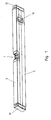
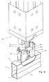
- FIGS. 1 to 15 A first embodiment of the invention is shown in FIGS. 1 to 15.
- the spirit level has a spirit level body 1, which is formed by a hollow profile, which has a bottom wall 2, a top wall 3 and side walls 4, 5, which connect the bottom wall and the top wall together.
- the bottom of the bottom wall 2 forms a measuring surface 6.
- the spirit level has to carry out a horizontal measurement, a horizontal vial 7, which is arranged in a window recess 8 of the spirit level body 1, for which purpose a holding device 9 is used.
- the spirit level further has to carry out a vertical measurement a vertical vial 10. This is also set in a window recess in the spirit level body by means of a holding device.
- This holding device of the vertical vial is irrelevant in connection with the present invention and therefore need not be explained further.
- This holding device for the vertical vial can in conventional Be formed manner. In principle, a vertical vial could also be omitted.
- end caps 50 may be inserted in the ends of the spirit level body 1 in the ends of the spirit level body 1 in the ends of the spirit level body 1 end caps 50 may be inserted.
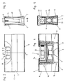
- the horizontal vial 7 may be formed in a conventional manner and have a vial body 11 with a barrel-shaped cavity into which a vial liquid containing a bubble 12 is filled. To mark the horizontal position of the dragonfly body 11 is provided with marking rings 13. The vial body 11 is glued into a frame 14 which surrounds this end face and on the underside, which is thus U-shaped in a side view.
- the vial body 11 is formed in the embodiment shown as a so-called relatively thick-walled "block vial” in which the vial body is first injected with a cylindrical or to its opening side (which is closed later) slightly conical cavity, which is turned out barrel-shaped in the episode.
- a training as a so-called “dragonfly” would be conceivable and possible, in which a relatively thin-walled dragonfly body is injected from the outset with a barrel-shaped cavity and forced demoulded.
- the holding device 9 for the horizontal vial 7 comprises a vial holder 15 and a clamping part 16.
- the vial holder 15 has support legs 17, the free ends of which are pressed in the assembled state of the holding device 9 to the inside of the bottom wall 2.
- the dragonfly socket 15 has a receiving space 18 for the horizontal vial 7. This is bounded by a bottom part 19 and on the longitudinal direction of the spirit level at both ends of the bottom part 19 mounted frontal parts 20, 21.
- At the side edges of the frontal parts 20, 21 are respectively from flange webs 22, which overlap vertical portions of the frame 14 in the inserted state of the horizontal vial.
- the two support feet 17 on a respective longitudinal side of the dragonfly socket 15 are connected to each other by a bridge portion 23, in which first and second recesses 24, 25 are arranged.
- bottom part 19 further comprises a through hole 26 and a transverse groove 27 are formed.
- this groove 27 is in the mounted state of the horizontal vial 7, a pivot web 28 which is formed on the underside of the frame 14, wherein the height of the pivot web 28 is greater than the depth of the groove 27.
- the clamping part 16 is formed as seen in side view U-shaped bracket and has two arms 29, 30, which in the assembled state of the holding device 9 with a normal 31st on the measuring surface 6 include an angle 32 of less than 45 °, said angle 32 is preferably less than 20 °, with a value of less than 10 ° is particularly preferred.
- the arms 29, 30 are interconnected by a connecting leg 33 running in the longitudinal direction of the spirit level body 1. At their remote from the connecting leg 33 free ends 34, 35, the arms 29, 30 are supported in the assembled state of the holding device 9 on the inside of the top wall 3 from.
- two hook parts 36 are arranged in the illustrated embodiment in the central region of its longitudinal extent.
- the two hook parts 36 are snapped into the two first recesses 24 of the bridge sections 23.
- the hook portions 36 are snapped into the second recesses 25, said second recesses 25 have a smaller height than the first recesses 24 so that the hook parts 36 can not snap over the entire length I (shown in FIG. 6) of their wedge-shaped latching noses but only over part of their length I (see, for example, FIG.
- the connecting leg 33 is elastically bendable and elastically bent in the assembled state of the holding device 9, as is apparent from FIGS. 4 and 13.
- the connecting leg 33 is located between the arranged on the two longitudinal sides of the bottom part 19 support legs 17.
- the arms 29, 30 extend in vertical longitudinal section (Fig. 4 and 13) seen on both sides of the level detection.
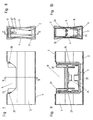
- Further guide bevels 37, 38 are arranged on the end-face parts 20, 21 of the leveling frame 15, which interact with the arms 29, 30 and which, when the tensioning part 16 is displaced into the mounted position of the holding device 9, the free ends 34, 35 of the arms 29, 30 slightly deflect in the direction of the front ends 39, 40 of the spirit level body 1 to bring the free ends 34, 35 of the arms 29, 30 on the top wall 3 in areas laterally of the window recess 8 for conditioning.
- the guide slopes 37, 38 are attached to the mutually remote outer sides of the frontal parts 20, 22, in the region of their ends remote from the bottom part 19.
- the connecting leg 33 has a passage opening 43, which is aligned in the assembled state of the holding device 9 with the passage opening 26 in the bottom part 19.
- the clamping part 16 is inserted with its hook parts 36 in the second recesses 25, as shown in Fig. 15.
- the so interconnected parts 15, 16 are inserted into the window recess 8 until the support legs 17 of the level bracket 15 rise on the bottom wall 2 (see Fig .. 7 to 10).
- the clamping part 16 is pulled in the direction of the top wall 3 until the hook parts 36 engage in the first recesses 24.
- the clamping member 16 is supported thereafter with the free ends 34, 35 of its arms 29, 30 on the inside of the top wall 3 and is elastically tensioned, whereby it presses the dragonfly socket 15 against the bottom wall 2.
- the holding device 9 is thus clamped between the top wall 3 and the bottom wall 2 (cf., FIGS. 11 to 14).
- the horizontal vial 7 is inserted into the receiving space 18 of the dragonfly socket 15, wherein it is rocker-like about the support line or partially cylindrical bearing surface of the pivot web 28 in the groove 27 is pivotable.
- the horizontal vial 7 is set in the vial holder 15 by making a rigid connection between these two parts, for example glued or welded.
- a cover 49 is attached and possibly glued, which covers the transition region between the Horizontalallelle 7 and the edge of the window recess 8.
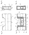
- FIG. 15 An assembly tool 44 for mounting the level detection is shown in Fig. 15 by way of example.
- the shaft 45 In a rotational position of the shaft 45, which is shown in Fig. 15, the head 46 through the through holes 26, 43 in the bottom part 19 and in the Connecting leg 33 feasible.
- the shaft 45 is rotated by 90 ° about its longitudinal axis, so that the head 46 engages behind the edge of the through hole 43 in the connecting leg 33.
- the shaft 45 is retracted axially (so that the head 46 moves in the direction of the top wall 3) until the hook parts 36 engage in the first latching recesses 24.
- FIG. 1 For bracing the holder 9 in spirit level body 1 here is a clamping screw 47 is present.
- the clamping screw 47 By means of the clamping screw 47, the clamping part 16 after insertion of the holding device in the window recess 8 is displaced in the direction of the top wall 3 and under the support of the free ends of its arms 29, 30 stretched on the inside of the top wall 3, whereby the dragonfly socket 15 is pressed against the bottom wall 2.
- FIG. 17 shows a further exemplary embodiment of the invention.
- a spring 48 acting between the bottom part 19 of the level detection frame 15 and the connecting leg 33 of the tensioning part 16 is present, which is designed here as a tension spring.
- the spring 48 is stretched so far that the free ends of the arms 29, 30 are below the guide slopes 37, 38.
- a suitable tool can be used which distances the connecting leg 33 correspondingly far from the bottom part 19.
- the tool After insertion into the window recess 8, the tool releases the parts, causing the spring 48 pulls the connecting leg 33 in the direction of the top wall, so that the free ends of the arms 29, 30 are pressed under bias of the spring 48 to the inside of the top wall 3 and the dragonfly socket 15 is pressed in response to the bottom wall 2.
- the clamping member 16 and the connecting leg 33 of the clamping member 16 may be formed inelastic in this embodiment.
- the clamping part 16 is displaceable parallel to the normal 31 on the measuring surface 6 with respect to the level of dragonflies 15. Also, a displacement at an angle to the normal 31 would be conceivable and possible, this angle is preferably less than 45 °.
Landscapes
- Engineering & Computer Science (AREA)
- General Physics & Mathematics (AREA)
- Radar, Positioning & Navigation (AREA)
- Remote Sensing (AREA)
- Physics & Mathematics (AREA)
- Manufacturing & Machinery (AREA)
- Medical Preparation Storing Or Oral Administration Devices (AREA)
- Measurement Of Levels Of Liquids Or Fluent Solid Materials (AREA)
- Details Of Rigid Or Semi-Rigid Containers (AREA)
- Clamps And Clips (AREA)
- Control Of Motors That Do Not Use Commutators (AREA)
- Force Measurement Appropriate To Specific Purposes (AREA)
- Sampling And Sample Adjustment (AREA)
Description
- Die Erfindung betrifft eine Wasserwaage mit einem aus einem Hohlprofil bestehenden Wasserwaagenkörper, der eine Bodenwand, deren Unterseite eine Messfläche bildet, eine Deckwand und die Bodenwand und die Deckwand verbindende Seitenwände aufweist, und mit einer Horizontallibelle für eine Horizontalmessung, die in einer Fensterausnehmung des Wasserwaagenkörpers angeordnet ist und im Wasserwaagenkörper mittels einer Haltevorrichtung befestigt ist, welche eine Libellenfassung, in der die Horizontallibelle festgelegt ist, und mindestens ein Spannteil aufweist, welches zum Verspannen der Haltevorrichtung im Wasserwaagenkörper gegenüber der Libellenfassung verschiebbar ist.
- Eine Wasserwaage der eingangs genannten Art ist aus der
DE 36 06 774 C2 bekannt. Die Libellenfassung weist Spreiznocken auf, die mit Spreizkörpern zusammenwirken, welche Spannteile bilden. Durch Verschieben der Spreizkörper ausgehend von ihrer Passivstellung in ihre Aktivstellung werden die Spreiznocken an die Innenseiten der Seitenwände des Wasserwaagenkörpers angedrückt, wodurch die Haltevorrichtung für die Horizontallibelle im Wasserwaagenkörper verspannt ist. Zwar ergibt sich bei der Einrichtung derDE 36 06 774 C2 eine einfache Montage der Haltevorrichtung für die Horizontallibelle im Wasserwaagenkörper, allerdings hat es sich gezeigt, dass bei Temperaturschwankungen die Justierung der Libelle gegenüber der Messfläche des Wasserwaagenkörpers nicht optimal beibehalten wird. Auch können Toleranzen des Profilquerschnitts des Wasserwaagenkörpers und der Teile der Haltevorrichtung nur sehr beschränkt aufgenommen werden. - Daneben sind auch in den Wasserwaagenkörper eingeklebte und in die Ausnehmung im Wasserwaagenkörper eingeschnappte Haltevorrichtungen für die Horizontallibelle bekannt. Auch hier tritt das Problem auf, dass durch Temperaturschwankungen die Messgenauigkeit beeinflusst wird.
- Es ist weiters eine Haltevorrichtung bekannt, bei der die in die Fensterausnehmung eingesetzte Libellenfassung mittels eines durch eine Spannschraube verstellbaren Spannteils an die Innenseite der Deckwand des Hohlprofils angedrückt wird. Die Justierung der Libelle gegenüber dem Wasserwaagenkörper erfolgt hierbei durch eine geringe plastische Verformung im Sinne eines Eindrückens der Deckwand des Wasserwaagenkörpers in einem Bereich, in welchem die Libellenfassung an die Deckwand angedrückt wird. Zwar ist das Temperaturverhalten dieser Haltevorrichtung gegenüber den zuvor beschriebenen Haltevorrichtungen besser, der Einbau und die Justierung sind aber relativ aufwändig. Auch wirken sich nachträgliche Verformungen der Deckwand (beispielsweise durch Stöße im Laufe der Benutzung der Wasserwaage) unmittelbar auf die Justierung der Horizontallibelle gegenüber der Messfläche aus.
- Aufgabe der Erfindung ist es, eine Wasserwaage bereitzustellen, bei der Temperaturschwankungen die Messgenauigkeit der Horizontallibelle möglichst wenig beeinflussen. Erfindungsgemäß gelingt dies durch eine Wasserwaage mit den Merkmalen des Patentanspruchs 1.
- Da das mindestens eine Spannteil die Libellenfassung an die Innenseite der Bodenwand andrückt, deren Unterseite die Messfläche bildet, kann trotz verschiedener Ausdehnungskoeffizienten der verschiedenen Teile (Wasserwaagenkörper, Libellenfassung, Spannteil und Libelle) der Einfluss auf die Messgenauigkeit äußerst klein gehalten werden. Unterschiedliche Ausdehnungswerte von Wasserkörper, Libellenfassung und Spannteil können vorteilhafterweise durch eine elastisch biegbare Ausbildung des Spannteils ausgeglichen werden. Ebenso können Querschnittstoleranzen des Wasserwaagenkörpers und Toleranzen der Einbauteile (Libellenfassung und Spannteil) vorteilhafterweise durch eine elastisch biegbare Ausbildung des Spannteils aufgenommen werden.
- In einer bevorzugten Ausführungsform der Erfindung ist das Spannteil als U-förmiger Bügel ausgebildet und weist zwei über einen Verbindungsschenkel verbundene Arme auf, deren vom Verbindungsschenkel abgelegene Enden sich an der Innenseite der Deckwand beidseitig (bezogen auf die Längsausdehnung des Wasserwaagenkörpers) der Fensteröffnung abstützen. Der Verbindungsschenkel kann hierbei im montierten Zustand der Haltevorrichtung mit der Libellenfassung verbunden sein (beispielsweise durch eine Schnappverbindung) und elastisch gebogen sein, wobei er eine Andrückkraft auf die Libellenfassung ausübt, mit der diese gegen die Bodenwand des Wasserwaagenkörpers gedrückt wird.
- Bevorzugterweise ist im montierten (= verspannten) Zustand der Haltevorrichtung das mindestens eine Spannteil mit der Libellenfassung durch eine Schnappverbindung verbunden (= verrastet). Dies ermöglicht eine sehr einfache Montage der Haltevorrichtung im Wasserwaagenkörper.
- Weitere Vorteile und Einzelheiten der Erfindung werden im Folgenden anhand der beiliegenden Zeichnung erläutert. In dieser zeigen:
- Fig. 1
- ein Ausführungsbeispiel einer erfindungsgemäßen Wasserwaage in perspektivischer Darstellung;
- Fig. 2
- eine Seitenansicht eines Ausschnitts der Wasserwaage im Bereich der Horizontallibelle;
- Fig. 3
- eine achsiale Ansicht des mittleren Ausschnitts von Fig. 2 (Blickrichtung C);
- Fig. 4
- einen vertikalen Längsschnitt entlang der Linie B-B von Fig. 3;
- Fig. 5
- einen Querschnitt entlang der Linie A-A von Fig. 2;
- Fig. 6
- eine Explosionsdarstellung der Teile der Wasserwaage des mittleren Ausschnitts von Fig. 2;
- Fig. 7
- eine Seitenansicht entsprechend Fig. 2 während der Montage der Haltevorrichtung (vor dem Verrasten des Spannteils mit der Libellenfassung);
- Fig. 8
- eine Ansicht analog Fig. 3 im Montagezustand entsprechend Fig. 7;
- Fig. 9
- einen vertikalen Längsschnitt entlang der Linie E-E von Fig. 8;
- Fig. 10
- einen Querschnitte entlang der Linie D-D von Fig. 7;
- die Fig.
- 11 bis 14 Darstellungen entsprechend der Fig. 7 bis 10, aber im miteinander verrasteten Zustand des Spannteils und der Libellenfassung;
- Fig. 15
- eine perspektivische Darstellung während der Montage mit einem Montagewerkzeug;
- Fig. 16
- eine perspektivische Darstellung eines weiteren Ausführungsbeispiels der Erfindung und
- Fig. 17
- einen vertikalen Längsmittelschnitt analog zu Fig. 13 eines weiteren Ausführungsbeispiels der Erfindung.
- Ein erstes Ausführungsbeispiel der Erfindung ist in den Fig. 1 bis 15 dargestellt. Die Wasserwaage besitzt einen Wasserwaagenkörper 1, der von einem Hohlprofil gebildet wird, welches eine Bodenwand 2, eine Deckwand 3 und Seitenwände 4, 5 aufweist, die die Bodenwand und die Deckwand miteinander verbinden. Die Unterseite der Bodenwand 2 bildet eine Messfläche 6. Die Wasserwaage besitzt zur Durchführung einer Horizontalmessung eine Horizontallibelle 7, die in einer Fensterausnehmung 8 des Wasserwaagenkörpers 1 angeordnet ist, zu welchem Zweck eine Haltevorrichtung 9 dient. Im gezeigten Ausführungsbeispiel, und wie dies bei Wasserwaagen üblich ist, besitzt die Wasserwaage weiters zur Durchführung einer Vertikalmessung eine Vertikallibelle 10. Diese ist ebenfalls in einer Fensterausnehmung im Wasserwaagenkörper mittels einer Haltevorrichtung festgelegt. Die Ausbildung der Haltevorrichtung der Vertikallibelle ist im Zusammenhang mit der vorliegenden Erfindung unerheblich und muss somit nicht weiter erläutert werden. Diese Haltevorrichtung für die Vertikallibelle kann in herkömmlicher Weise ausgebildet sein. Grundsätzlich könnte eine Vertikallibelle auch entfallen. In die Enden des Wasserwaagenkörpers 1 können Endkappen 50 eingesteckt sein.
- Die Horizontallibelle 7 kann in herkömmlicher Weise ausgebildet sein und einen Libellenkörper 11 mit einem tonnenförmigen Hohlraum aufweisen, in den eine Libellenflüssigkeit eingefüllt ist, die eine Blase 12 enthält. Zur Markierung der Horizontallage ist der Libellenkörper 11 mit Markierungsringen 13 versehen. Der Libellenkörper 11 ist in einen diesen stirnseitig und an der Unterseite umgebenden Rahmen 14, der in Seitenansicht somit U-förmig ausgebildet ist, eingeklebt.
- Der Libellenkörper 11 ist im gezeigten Ausführungsbeispiel als sogenannte relativ dickwandige "Blocklibelle" ausgebildet, bei welcher der Libellenkörper zunächst mit einem zylindrischen bzw. zu seiner Öffnungsseite (die später verschlossen wird) hin leicht konischen Hohlraum gespritzt wird, welcher in der Folge tonnenförmig ausgedreht wird. Auch eine Ausbildung als sogenannte "Röhrenlibelle" wäre denkbar und möglich, bei der ein relativ dünnwandiger Libellenkörper von vorne herein mit einem tonnenförmigen Hohlraum gespritzt wird und zwangsentformt wird.
- Die Haltevorrichtung 9 für die Horizontallibelle 7 umfasst eine Libellenfassung 15 und ein Spannteil 16. Die Libellenfassung 15 besitzt Stützfüße 17, deren freie Enden im montierten Zustand der Haltevorrichtung 9 an die Innenseite der Bodenwand 2 angedrückt sind. Weiters besitzt die Libellenfassung 15 einen Aufnahmeraum 18 für die Horizontallibelle 7. Dieser wird von einem Bodenteil 19 und auf die Längsrichtung der Wasserwaage bezogen an beiden Enden des Bodenteils 19 angebrachten stirnseitigen Teile 20, 21 begrenzt. An den Seitenrändern der stirnseitigen Teile 20, 21 stehen jeweils Flanschstege 22 ab, welche im eingesetzten Zustand der Horizontallibelle vertikale Abschnitte des Rahmens 14 überlappen. Die beiden Stützfüße 17 an einer jeweiligen Längsseite der Libellenfassung 15 sind durch einen Brückenabschnitt 23 miteinander verbunden, in welchem erste und zweite Rastausnehmungen 24, 25 angeordnet sind.
- Im Bodenteil 19 sind weiters eine Durchgangsöffnung 26 und eine querverlaufende Rinne 27 ausgebildet. In dieser Rinne 27 liegt im montierten Zustand der Horizontallibelle 7 ein Schwenksteg 28, der an der Unterseite des Rahmens 14 ausgebildet ist, wobei die Höhe des Schwenkstegs 28 größer als die Tiefe der Rinne 27 ist.
- Das Spannteil 16 ist als in Seitenansicht gesehen U-förmiger Bügel ausgebildet und besitzt zwei Arme 29, 30, welche im montierten Zustand der Haltevorrichtung 9 mit einer Normalen 31 auf die Messfläche 6 einen Winkel 32 von weniger als 45° einschließen, wobei dieser Winkel 32 bevorzugterweise weniger als 20° beträgt, wobei ein Wert von weniger als 10° besonders bevorzugt ist. Die Arme 29, 30 sind durch einen in Längsrichtung des Wasserwaagenkörpers 1 verlaufenden Verbindungsschenkel 33 miteinander verbunden. An ihren vom Verbindungsschenkel 33 abgelegenen freien Enden 34, 35 stützen sich die Arme 29, 30 im montierten Zustand der Haltevorrichtung 9 an der Innenseite der Deckwand 3 ab.
- Am Verbindungsschenkel 33 sind im gezeigten Ausführungsbeispiel im mittleren Bereich seiner Längsausdehnung zwei Hakenteile 36 angeordnet. Im montierten Zustand der Haltevorrichtung 9 sind die beiden Hakenteile 36 in die beiden ersten Rastausnehmungen 24 der Brückenabschnitte 23 eingeschnappt. In einer Vorraststellung, in welcher die Haltevorrichtung 9 in die Fensterausnehmung 8 für ihre Montage eingesetzt wird (vgl. Fig. 15) sind die Hakenteile 36 in die zweiten Rastausnehmungen 25 eingeschnappt, wobei diese zweiten Rastausnehmungen 25 eine kleinere Höhe als die ersten Rastausnehmungen 24 aufweisen, sodass die Hakenteile 36 nicht über die gesamte Länge I (in Fig. 6 eingezeichnet) ihrer keilförmigen Rastnasen einschnappen können sondern nur über einen Teil ihrer Länge I (vgl. z. B. Fig. 10).
- Der Verbindungsschenkel 33 ist elastisch biegbar ausgebildet und im montierten Zustand der Haltevorrichtung 9 elastisch gebogen, wie dies aus den Fig. 4 und 13 ersichtlich ist.
- Im montierten Zustand der Haltevorrichtung 9 liegt der Verbindungsschenkel 33 zwischen den an den beiden Längsseiten des Bodenteils 19 angeordneten Stützfüßen 17. Die Arme 29, 30 erstrecken sich im vertikalen Längsschnitt (Fig. 4 bzw. 13) gesehen beidseitig der Libellenfassung.
- An den stirnseitigen Teilen 20, 21 der Libellenfassung 15 sind weiters Führungsschrägen 37, 38 angeordnet, die mit den Armen 29, 30 zusammenwirken und welche beim Verschieben des Spannteils 16 in die montierte Stellung der Haltevorrichtung 9 die freien Enden 34, 35 der Arme 29, 30 etwas in Richtung zu den stirnseitigen Enden 39, 40 des Wasserwaagenkörpers 1 auslenken, um die freien Enden 34, 35 der Arme 29, 30 an der Deckwand 3 in Bereichen seitlich der Fensterausnehmung 8 zur Anlage zu bringen. Die Führungsschrägen 37, 38 sind an den voneinander abgewandten Außenseiten der stirnseitigen Teile 20, 22 angebracht, und zwar im Bereich ihrer vom Bodenteil 19 abgelegenen Enden.
- An den Außenseiten der stirnseitigen Teile 20, 21 sind weiters Führungsnasen 41 angeordnet, die mit Führungsnuten 42 in den Armen 29, 30 zusammenwirken.
- Der Verbindungsschenkel 33 weist eine im montierten Zustand der Haltevorrichtung 9 mit der Durchgangsöffnung 26 im Bodenteil 19 fluchtende Durchgangsöffnung 43 auf.
- Zur Montage der Haltevorrichtung wird das Spannteil 16 mit seinen Hakenteilen 36 in die zweiten Rastausnehmungen 25 eingesetzt, wie dies in Fig. 15 dargestellt ist. In der Folge werden die so miteinander verbundenen Teile 15, 16 in die Fensterausnehmung 8 eingesetzt, bis die Stützfüße 17 der Libellenfassung 15 auf der Bodenwand 2 aufstehen (vgl. Fig. 7 bis 10). In der Folge wird das Spannteil 16 in Richtung zur Deckwand 3 gezogen, bis die Hakenteile 36 in die ersten Rastausnehmungen 24 einrasten. Das Spannteil 16 stützt sich hiernach mit den freien Enden 34, 35 seiner Arme 29, 30 an der Innenseite der Deckwand 3 ab und ist elastisch gespannt, wodurch es die Libellenfassung 15 gegen die Bodenwand 2 drückt. Die Haltevorrichtung 9 ist damit zwischen der Deckwand 3 und der Bodenwand 2 verspannt (vgl. Fig. 11 bis 14).
- In der Folge wird die Horizontallibelle 7 in den Aufnahmeraum 18 der Libellenfassung 15 eingesetzt, wobei sie wippenartig um die Auflagelinie bzw. teilzylindrische Auflagefläche des Schwenkstegs 28 in der Rinne 27 verschwenkbar ist. Nach der exakten Justierung der Horizontallibelle 7 in der Libellenfassung 15 wird die Horizontallibelle 7 in der Libellenfassung 15 durch Herstellung einer starren Verbindung zwischen diesen beiden Teilen festgelegt, beispielsweise verklebt oder verschweißt.
- Weiters wird noch eine Abdeckung 49 aufgesteckt und gegebenenfalls verklebt, welche den Übergangsbereich zwischen der Horizontalliebelle 7 und dem Rand der Fensterausnehmung 8 überdeckt.
- Ein Montagewerkzeug 44 für die Montage der Libellenfassung ist in Fig. 15 beispielhaft dargestellt. Das Montagewerkzeug 44 besitzt einen an einem achsial verstellbaren und um seine Längsachse verdrehbaren Schaft 45 angeordneten Kopf 46. In einer Drehstellung des Schaftes 45, die in Fig. 15 dargestellt ist, ist der Kopf 46 durch die Durchgangsöffnungen 26, 43 im Bodenteil 19 und im Verbindungsschenkel 33 durchführbar. In der Folge wird der Schaft 45 um 90° um seine Längsachse verdreht, sodass der Kopf 46 den Rand der Durchgangsöffnung 43 im Verbindungsschenkel 33 hintergreift. In der Folge wird der Schaft 45 achsial zurückgezogen (sodass sich der Kopf 46 in Richtung zur Deckwand 3 bewegt), bis die Hakenteile 36 in den ersten Rastausnehmungen 24 einrasten.
- Ein weiteres Ausführungsbeispiel der Erfindung ist in Fig. 16 dargestellt. Zur Verspannung der Haltevorrichtung 9 im Wasserwaagenkörper 1 ist hier eine Spannschraube 47 vorhanden. Mittels der Spannschraube 47 wird das Spannteil 16 nach dem Einsetzen der Haltevorrichtung in die Fensterausnehmung 8 in Richtung zur Deckwand 3 verschoben und unter Abstützung der freien Enden seiner Arme 29, 30 an der Innenseite der Deckwand 3 gespannt, wodurch die Libellenfassung 15 gegen die Bodenwand 2 gedrückt wird.
- Ein weiteres Ausführungsbeispiel der Erfindung zeigt Fig. 17. Es ist hier eine zwischen dem Bodenteil 19 der Libellenfassung 15 und dem Verbindungsschenkel 33 des Spannteils 16 wirkende Feder 48 vorhanden, welche hier als Zugfeder ausgebildet ist. Zum Einsetzen der Haltevorrichtung 9 in die Fensterausnehmung 8 wird die Feder 48 soweit gespannt, dass die freien Enden der Arme 29, 30 unterhalb der Führungsschrägen 37, 38 liegen. Hierzu kann ein geeignetes Werkzeug eingesetzt werden, welches den Verbindungsschenkel 33 entsprechend weit vom Bodenteil 19 beabstandet. Nach dem Einsetzen in die Fensterausnehmung 8 gibt das Werkzeug die Teile frei, wodurch die Feder 48 den Verbindungsschenkel 33 in Richtung zur Deckwand zieht, sodass sich die freien Enden der Arme 29, 30 unter Vorspannung der Feder 48 an die Innenseite der Deckwand 3 angedrückt werden und die Libellenfassung 15 im Gegenzug an die Bodenwand 2 angedrückt wird. Das Spannteil 16 bzw. der Verbindungsschenkel 33 des Spannteils 16 kann in diesem Ausführungsbeispiel auch unelastisch ausgebildet sein.
- Unterschiedliche Modifikationen der gezeigten Ausführungsbeispiele sind denkbar und möglich, ohne den Bereich der Erfindung zu verlassen. So wäre es beispielsweise denkbar und möglich, mehr als ein Spannteil vorzusehen und das oder die Spannteile könnten auch eine andere als die gezeigte bügelartige Form aufweisen, wobei jeweils bevorzugt ist, dass das oder die Spannteile in Längsrichtung des Wasserwaagenkörpers gesehen beidseitig der Fensterausnehmung 8 an der Innenseite der Deckwand 3 anliegen. Die Fensterausnehmung 8 könnte auch größer oder kleiner als in den gezeigten Ausführungsbeispielen ausgebildet sein, in welchen sie jeweils eine Ausnehmung der Deckwand 3 und an die Deckwand 3 anschließende obere Abschnitte der Seitenwände 4, 5 umfasst.
- In den gezeigten Ausführungsbeispielen ist der Spannteil 16 parallel zur Normalen 31 auf die Messfläche 6 gegenüber der Libellenfassung 15 verschiebbar. Auch eine Verschiebbarkeit unter einem Winkel zur Normalen 31 wäre denkbar und möglich, wobei dieser Winkel bevorzugterweise weniger als 45° beträgt.
-
- 1
- Wasserwaagenkörper
- 2
- Bodenwand
- 3
- Deckwand
- 4
- Seitenwand
- 5
- Seitenwand
- 6
- Messfläche
- 7
- Horizontallibelle
- 8
- Fensterausnehmung
- 9
- Haltevorrichtung
- 10
- Vertikallibelle
- 11
- Libellenkörper
- 12
- Blase
- 13
- Markierungsring
- 14
- Rahmen
- 15
- Libellenfassung
- 16
- Spannteil
- 17
- Stützfuß
- 18
- Aufnahmeraum
- 19
- Bodenteil
- 20
- stirnseitiges Teil
- 21
- stirnseitiges Teil
- 22
- Flanschsteg
- 23
- Brückenabschnitt
- 24
- Rastausnehmung
- 25
- Rastausnehmung
- 26
- Durchgangsöffnung
- 27
- Rinne
- 28
- Schwenksteg
- 29
- Arm
- 30
- Arm
- 31
- Normale
- 32
- Winkel
- 33
- Verbindungsschenkel
- 34
- Ende
- 35
- Ende
- 36
- Hakenteil
- 37
- Führungsschräge
- 38
- Führungsschräge
- 39
- stirnseitiges Ende
- 40
- stirnseitiges Ende
- 41
- Führungsnase
- 42
- Führungsnut
- 43
- Durchgangsöffnung
- 44
- Montagewerkzeug
- 45
- Schaft
- 46
- Kopf
- 47
- Spannschraube
- 48
- Feder
- 49
- Abdeckung
- 40
- Endkappe
Claims (19)
- Wasserwaage mit einem aus einem Hohlprofil bestehenden Wasserwaagenkörper (1), der eine Bodenwand (2), deren Unterseite eine Messfläche (6) bildet, eine Deckwand (3) und die Bodenwand (2) und die Deckwand (3) verbindende Seitenwände (4, 5) aufweist, und mit einer Horizontallibelle (7) für eine Horizontalmessung, die in einer Fensterausnehmung (8) des Wasserwaagenkörpers (1) angeordnet ist und im Wasserwaagenkörper (1) mittels einer Haltevorrichtung (9) befestigt ist, welche im Wasserwaagenkörper (1) verspannt ist und eine Libellenfassung (15), in der die Horizontallibelle (7) festgelegt ist, und mindestens ein Spannteil (16) aufweist, welches zum Verspannen der Haltevorrichtung (9) im Wasserwaagenkörper (1) verschiebbar gegenüber der Libellenfassung (15) ist, wobei das mindestens eine Spannteil (16) gegenüber der Libellenfassung (15) in eine Richtung verschiebbar ist, die einen Winkel von weniger als 45° mit einer Normalen (31) auf die Messfläche (6) einschließt, dadurch gekennzeichnet, dass im verspannten Zustand der Haltevorrichtung (9) das mindestens eine Spannteil (16) sich an der Innenseite der Deckwand (3) abstützt und die Libellenfassung (15) vom Spannteil (16) an die Innenseite der Bodenwand (2) angedrückt ist.
- Wasserwaage nach Anspruch 1, dadurch gekennzeichnet, dass das Spannteil (16) zwei Arme (29, 30) aufweist, die im montierten Zustand der Haltevorrichtung (9) einen Winkel (32) von weniger als 45°, bevorzugterweise von weniger als 20°, mit einer Normalen (31) auf die Messfläche (6) einschließen und von einem Verbindungsschenkel (33) verbunden sind und deren vom Verbindungsschenkel (33) abgelegenen Enden (34, 35) sich im vertikalen Längsschnitt des Wasserwaagenkörpers (1) gesehen beidseitig der Fensterausnehmung (8) an der Innenseite der Deckwand (3) abstützen.
- Wasserwaage nach Anspruch 2, dadurch gekennzeichnet, dass sich die Arme (29, 30) im vertikalen Längsschnitt des Wasserwaagenkörpers (1) gesehen beidseitig der Libellenfassung (15) erstrecken.
- Wasserwaage nach Anspruch 2 oder Anspruch 3, dadurch gekennzeichnet, dass der Verbindungsschenkel (33) zwischen Stützfüßen (17) der Libellenfassung (15) liegt, die in einem Querschnitt des Wasserwaagenkörpers (1) gesehen beidseitig des Verbindungsschenkels (33) liegen und die mit ihren freien Enden an die Innenseite der Bodenwand (2) angedrückt sind.
- Wasserwaage nach einem der Ansprüche 1 bis 4, dadurch gekennzeichnet, dass im verspannten Zustand der Haltevorrichtung (9) das mindestens eine Spannteil (16) mit der Libellenfassung (15) durch eine Schnappverbindung verrastet ist.
- Wasserwaage nach einem der Ansprüche 2 bis 5, dadurch gekennzeichnet, dass am Verbindungsschenkel (33), vorzugsweise im mittleren Bereich der Längsausdehnung des Verbindungsschenkels (33), mindestens ein Hakenteil (36) angeordnet ist, das im verspannten Zustand der Haltevorrichtung in eine Rastausnehmung (24) der Libellenfassung (15) eingeschnappt ist.
- Wasserwaage nach Anspruch 6, dadurch gekennzeichnet, dass zwei im Querschnitt des Wasserwaagenkörpers gesehen an gegenüberliegenden Längsseiten des Verbindungsschenkels (33) angeordnete und in Rastausnehmungen (24) eingeschnappte Hakenteile (36) vorhanden sind.
- Wasserwaage nach Anspruch 6 oder Anspruch 7, dadurch gekennzeichnet, dass für jedes Hakenteil (36) zusätzlich zur ersten Rastausnehmung (24) eine zweite Rastausnehmung (25) der Libellenfassung (15) vorhanden ist, in welche das Hakenteil (36) in einer Vorrastposition des Spannteils (16) beim Einsetzen der Haltevorrichtung (9) in die Fensterausnehmung (8) eingerastet ist.
- Wasserwaage nach einem der Ansprüche 1 bis 5, dadurch gekennzeichnet, dass zur Verspannung der Haltevorrichtung (9) im Wasserwaagenkörper (1) mindestens eine zwischen der Libellenfassung (15) und dem mindestens einen Spannteil (16) wirkende Spannschraube (47) vorhanden ist.
- Wasserwaage nach einem der Ansprüche 1 bis 5, dadurch gekennzeichnet, dass zur Verspannung der Haltevorrichtung (9) im Wasserwaagenkörper (1) mindestens eine zwischen der Libellenfassung (15) und dem mindestens einen Spannteil (16) wirkende Feder (48) vorhanden ist.
- Wasserwaage nach einem der Ansprüche 1 bis 10, dadurch gekennzeichnet, dass das mindestens eine Spannteil (16) in eine Richtung verschiebbar ist, die parallel zur Normalen (31) auf die Messfläche (6) ist.
- Wasserwaage nach einem der Ansprüche 2 bis 11, dadurch gekennzeichnet, dass an der Libellenfassung (15) mit den Armen (29, 30) des Spannteils (16) zusammenwirkende Führungsschrägen (37, 38) angeordnet sind, welche beim Verschieben des Spannteils (16) in Richtung zur Deckwand (3) die freien Enden (34, 35) der Arme (29, 30) für ihre Anlage an seitlich der Fensterausnehmung (8) liegenden Bereichen der Deckwand (3) in Richtung zu den stirnseitigen Enden (39, 40) des Wasserwaagenkörpers (1) auslenken.
- Wasserwaage nach Anspruch 12, dadurch gekennzeichnet, dass die Führungsschrägen an den voneinander abgewandten Außenseiten von stirnseitigen Teilen (20, 21) der Libellenfassung (15) im Bereich der der Deckwand (3) zugewandten Enden dieser stirnseitigen Teile (20, 21) angeordnet sind.
- Wasserwaage nach einem Ansprüche 1 bis 13, dadurch gekennzeichnet, dass die Libellenfassung (15) einen Aufnahmeraum (18) für die Horizontallibelle (7) aufweist, der in Richtung zur Bodenwand (2) des Wasserwaagenkörpers von einem Bodenteil (19) und in Richtung zu den stirnseitigen Enden (39, 40) des Wasserwaagenkörpers (1)von stirnseitigen Teilen (20, 21) begrenzt wird.
- Wasserwaage nach Anspruch 14, dadurch gekennzeichnet, dass die Stützfüße (17) der Libellenfassung (15) vom Bodenteil (19) in Richtung zur Bodenwand (2) des Wasserwaagenkörpers (1) abstehen, wobei bevorzugterweise an beiden längsseitigen Rändern des Bodenteils (19) Stützfüße (17) angeordnet sind.
- Wasserwaage nach einem der Ansprüche 2 bis 15, dadurch gekennzeichnet, dass der Verbindungsschenkel (33) elastisch biegbar ist und im verspannten Zustand der Haltevorrichtung (9) elastisch gebogen ist.
- Verfahren zur Montage einer Horizontallibelle (7) in einer Fensterausnehmung (8) eines Wasserwaagenkörpers (1), der von einem Hohlprofil gebildet wird und eine Bodenwand (2), deren Unterseite eine Messfläche (6) bildet, eine Deckwand (3) und die Bodenwand (2) und die Deckwand (3) verbindende Seitenwände (4, 5) aufweist, wobei eine Haltevorrichtung (9), die eine Libellenfassung (15), an der die Horizontallibelle (7) befestigt ist, und mindestens ein Spannteil (16) aufweist, in die Fensterausnehmung (8) des Wasserwaagenkörpers (1) eingesetzt wird und in der Folge das mindestens eine Spannteil (16) gegenüber der Libellenfassung (15) in eine Richtung verschoben wird, die mit einer Normalen (31) auf die Messfläche (6) einen Winkel von weniger als 45° einschließt, wobei die. Haltevorrichtung (9) im Wasserwaagenkörper (1) verspannt wird, dadurch gekennzeichnet, dass zur Verspannung der Haltevorrichtung (9) im Wasserwaagenkörper (1) das Spannteil (16) von einer von der Deckwand (3) distanzierten Position in eine an der Innenseite der Deckwand (3) angedrückte Position verschoben wird, wobei die Libellenfassung (15) vom sich an der Deckwand (3) abstützenden Spannteil (16) an die Innenseite der Bodenwand (2) angedrückt wird und die Haltevorrichtung (9) zwischen der Deckwand (3) und der Bodenwand (2) verspannt wird.
- Verfahren.nach Anspruch 17, dadurch gekennzeichnet, dass das mindestens eine Spannteil (16) und die Libellenfassung (15) zum Verspannen zwischen der Deckwand (3) und der Bodenwand (2) miteinander verrastet werden.
- Verfahren nach Anspruch 18, dadurch gekennzeichnet, dass die Libellenfassung (15) und das mindestens eine Spannteil (16) in einem vorverrasteten Zustand in die Fensterausnehmung (8) eingesetzt werden und in der Folge mittels eines Montagewerkzeuges (44), welch.es einen an einem in Achsialrichtung verstellbaren und um seine Längsachse verdrehbaren Schaft (45) angeordneten Kopf (46) aufweist, durch Durchführen des Kopfes (46) durch Durchgangsöffnungen (26) in der Libellenfassung (15) und Durchgangsöffnungen (43) im Spannteil (16) und Hintergreifen der Ränder der Durchgangsöffnung (43) im Spannteil (16) unter Verdrehung des Schaftes (45) um seine Längsachse und anschließendes Zurückziehen des Kopfes (46) verspannt und in ihren verrasteten Zustand gebracht werden.
Applications Claiming Priority (2)
| Application Number | Priority Date | Filing Date | Title |
|---|---|---|---|
| AT1122004 | 2004-01-28 | ||
| AT0011204A AT414044B (de) | 2004-01-28 | 2004-01-28 | Wasserwaage |
Publications (2)
| Publication Number | Publication Date |
|---|---|
| EP1559997A1 EP1559997A1 (de) | 2005-08-03 |
| EP1559997B1 true EP1559997B1 (de) | 2008-01-23 |
Family
ID=34637609
Family Applications (1)
| Application Number | Title | Priority Date | Filing Date |
|---|---|---|---|
| EP04029421A Expired - Lifetime EP1559997B1 (de) | 2004-01-28 | 2004-12-13 | Wasserwaage |
Country Status (6)
| Country | Link |
|---|---|
| US (1) | US7765706B2 (de) |
| EP (1) | EP1559997B1 (de) |
| CN (1) | CN100554881C (de) |
| AT (2) | AT414044B (de) |
| DE (1) | DE502004006038D1 (de) |
| ES (1) | ES2300698T3 (de) |
Families Citing this family (25)
| Publication number | Priority date | Publication date | Assignee | Title |
|---|---|---|---|---|
| IL149274A0 (en) * | 2002-04-22 | 2002-11-10 | Kapro Ind Ltd | Bubble vial assembly and method therefor |
| JP4275112B2 (ja) * | 2005-07-20 | 2009-06-10 | 株式会社エビス | 水準器 |
| US7464479B2 (en) * | 2006-05-18 | 2008-12-16 | The Stanley Works | Level vial and manufacturing method therefor |
| US7472486B2 (en) * | 2006-05-19 | 2009-01-06 | The Stanley Works | Level with vial and manufacturing method therefor |
| US7472487B2 (en) | 2006-05-26 | 2009-01-06 | The Stanley Works | Level |
| US7832112B2 (en) * | 2008-11-10 | 2010-11-16 | Empire Level Mfg. Co. | Vial-mounting structure |
| AU2015261616B2 (en) * | 2009-10-29 | 2016-12-15 | Milwaukee Electric Tool Corporation | Box level |
| CA2936492C (en) * | 2009-10-29 | 2018-06-19 | Milwaukee Electric Tool Corporation | Box level |
| AT509146B1 (de) | 2009-11-16 | 2011-10-15 | Sola Messwerkzeuge Gmbh | Wasserwaage |
| WO2011139979A1 (en) * | 2010-05-03 | 2011-11-10 | Allemand James S | Lighted level tool |
| CN102445215B (zh) * | 2011-09-26 | 2013-06-12 | 中国航空工业第六一八研究所 | 用于挠性陀螺信号器测试的升降装置 |
| US8914987B2 (en) | 2012-01-31 | 2014-12-23 | Stanley Black & Decker, Inc. | I-beam level |
| US9625260B2 (en) | 2014-04-16 | 2017-04-18 | Stanley Black & Decker, Inc. | Carbon fiber composite level and method of manufacturing same |
| CN107209013A (zh) | 2014-11-13 | 2017-09-26 | 米沃奇电动工具公司 | 包括可移除的端盖的水平仪 |
| AT517233B1 (de) | 2015-07-07 | 2016-12-15 | Sola-Messwerkzeuge Gmbh | Wasserwaage |
| TWM523092U (zh) * | 2015-11-09 | 2016-06-01 | Woodson Company Ltd | 水平尺改良結構 |
| US20170343347A1 (en) * | 2016-05-26 | 2017-11-30 | Ching Lin Plastic Industry Co., Ltd. | Easy assembly level |
| WO2018119075A1 (en) * | 2016-12-21 | 2018-06-28 | Milwaukee Electric Tool Corporation | Level with removable end cap |
| US10845193B2 (en) | 2016-12-21 | 2020-11-24 | Milwaukee Electric Tool Corporation | Level with removable end cap |
| US11085762B2 (en) | 2018-04-27 | 2021-08-10 | Milwaukee Electric Tool Corporation | Level with removable end cap with wall grip |
| CN111989542B (zh) * | 2018-04-27 | 2022-10-25 | 米沃奇电动工具公司 | 具有带有壁卡持部的可移除端盖的水平仪 |
| US11193764B2 (en) | 2019-01-17 | 2021-12-07 | Milwaukee Electric Tool Corporation | Two datum vial mounting system and method |
| WO2020150484A1 (en) | 2019-01-17 | 2020-07-23 | Milwaukee Electric Tool Corporation | Two datum vial mounting system and method |
| US10928197B2 (en) | 2019-02-07 | 2021-02-23 | Diamond Tech LLC | Level vial mounting system for a box beam level |
| CN116295534B (zh) * | 2023-04-23 | 2023-08-18 | 河北省科学院应用数学研究所 | 水准泡温漂检测方法及系统 |
Family Cites Families (10)
| Publication number | Priority date | Publication date | Assignee | Title |
|---|---|---|---|---|
| US1393328A (en) * | 1920-03-25 | 1921-10-11 | Fred Ohde | Level device |
| US1624161A (en) * | 1926-03-01 | 1927-04-12 | Day Jacob | Spirit level |
| DE3127399A1 (de) * | 1981-07-10 | 1983-01-27 | Stabila-Messgeräte Gustav Ullrich GmbH & Co KG, 6747 Annweiler | Wasserwaage |
| DE3432911A1 (de) * | 1984-09-07 | 1986-03-20 | Scheyer, Guido, Ing., Götzis | Wasserwaage |
| DE3606774A1 (de) * | 1986-03-01 | 1987-09-03 | Keller Bayer Mass Ind | Vorrichtung zum befestigen der libelle einer wasserwaage |
| CH690200A5 (de) * | 1995-09-29 | 2000-05-31 | Mapo Ag | Wasserwaage mit Magnethaftung |
| JP3748681B2 (ja) * | 1997-08-29 | 2006-02-22 | 株式会社ガスター | 一缶二水路風呂給湯器 |
| JP3754537B2 (ja) * | 1997-09-17 | 2006-03-15 | 株式会社ガスター | 一缶二水路給湯器 |
| JP3073950B2 (ja) * | 1997-12-24 | 2000-08-07 | 株式会社エビス | 水準器 |
| JP3073951B2 (ja) * | 1997-12-25 | 2000-08-07 | 株式会社エビス | 水準器 |
-
2004
- 2004-01-28 AT AT0011204A patent/AT414044B/de not_active IP Right Cessation
- 2004-12-13 AT AT04029421T patent/ATE384932T1/de active
- 2004-12-13 DE DE502004006038T patent/DE502004006038D1/de not_active Expired - Lifetime
- 2004-12-13 EP EP04029421A patent/EP1559997B1/de not_active Expired - Lifetime
- 2004-12-13 ES ES04029421T patent/ES2300698T3/es not_active Expired - Lifetime
-
2005
- 2005-01-26 US US11/043,421 patent/US7765706B2/en not_active Expired - Fee Related
- 2005-01-27 CN CNB2005100677338A patent/CN100554881C/zh not_active Expired - Fee Related
Also Published As
| Publication number | Publication date |
|---|---|
| CN1664503A (zh) | 2005-09-07 |
| DE502004006038D1 (de) | 2008-03-13 |
| ATA1122004A (de) | 2005-11-15 |
| AT414044B (de) | 2006-08-15 |
| ES2300698T3 (es) | 2008-06-16 |
| US7765706B2 (en) | 2010-08-03 |
| CN100554881C (zh) | 2009-10-28 |
| US20050160610A1 (en) | 2005-07-28 |
| EP1559997A1 (de) | 2005-08-03 |
| ATE384932T1 (de) | 2008-02-15 |
Similar Documents
| Publication | Publication Date | Title |
|---|---|---|
| EP1559997B1 (de) | Wasserwaage | |
| EP0226785A2 (de) | Eckumlenkeinrichtung eines Riegelstangenbeschlages eines Fensters oder einer Tür | |
| DE2630763B2 (de) | Haltevorrichtung für teleskopartig ineinander verschiebbare Stangen mit ähnlichem Querschnitt | |
| DE2342113A1 (de) | Moebelscharnier mit verstellbarem scharnierarm | |
| DE19901775A1 (de) | T-Verbindung zwischen einem Sprossen- und einem Pfostenprofil einer Fassade oder eines Lichtdaches | |
| DE202005015034U1 (de) | Gleitstück für einen Beschlag | |
| DE19828382C2 (de) | Anordnung zum Befestigen eines einen Hohlquerschnitt aufweisenden Pfostens am Blendrahmen eines Fensters oder einer Türe aus Kunststoff oder Leichtmetall | |
| EP0010260B1 (de) | Schraubzwinge | |
| EP0529229A1 (de) | Dübel | |
| DE4345103C2 (de) | Vorrichtung zur Befestigung von winkeligen Installationselementen | |
| DE3147306C2 (de) | Leiter | |
| DE2923903A1 (de) | Wandbefestigungselement fuer plattenheizkoerper | |
| AT410978B (de) | Wasserwaage mit einem hohlprofil | |
| DE3308812A1 (de) | Trag- und laufrollenvorrichtung fuer schiebetueren | |
| DE2509071C2 (de) | Markisenkasten mit Lager für eine Tuchrolle | |
| DE2601390A1 (de) | Eckumlenkung fuer treibstangenbeschlaege von fenstern, tueren o.dgl. | |
| DE3728759A1 (de) | Dehnschraube fuer kieferdehnvorrichtungen | |
| AT326299B (de) | Festhalter zum fixieren von in einer innenläuferschiene geführten tragkorpern für vorhänge od.dgl. | |
| EP4379176A2 (de) | Bandtasche | |
| EP0291973A2 (de) | Verbindungsstück für zwei winklig aneinanderstossende Profilstäbe von Fenster oder Türrahmen | |
| DE202025104335U1 (de) | Vorrichtung zur Montage eines Fensterrahmens an einem Rolladenkasten | |
| DE2322258A1 (de) | Scharnierband | |
| EP1045103A2 (de) | Sprossenfenster | |
| DE102023106390A1 (de) | Bohrschablone | |
| DE9304538U1 (de) | Verbindungsvorrichtung |
Legal Events
| Date | Code | Title | Description |
|---|---|---|---|
| PUAI | Public reference made under article 153(3) epc to a published international application that has entered the european phase |
Free format text: ORIGINAL CODE: 0009012 |
|
| AK | Designated contracting states |
Kind code of ref document: A1 Designated state(s): AT BE BG CH CY CZ DE DK EE ES FI FR GB GR HU IE IS IT LI LT LU MC NL PL PT RO SE SI SK TR |
|
| AX | Request for extension of the european patent |
Extension state: AL BA HR LV MK YU |
|
| 17P | Request for examination filed |
Effective date: 20060114 |
|
| AKX | Designation fees paid |
Designated state(s): AT BE BG CH CY CZ DE DK EE ES FI FR GB GR HU IE IS IT LI LT LU MC NL PL PT RO SE SI SK TR |
|
| GRAP | Despatch of communication of intention to grant a patent |
Free format text: ORIGINAL CODE: EPIDOSNIGR1 |
|
| GRAS | Grant fee paid |
Free format text: ORIGINAL CODE: EPIDOSNIGR3 |
|
| GRAA | (expected) grant |
Free format text: ORIGINAL CODE: 0009210 |
|
| AK | Designated contracting states |
Kind code of ref document: B1 Designated state(s): AT BE BG CH CY CZ DE DK EE ES FI FR GB GR HU IE IS IT LI LT LU MC NL PL PT RO SE SI SK TR |
|
| REG | Reference to a national code |
Ref country code: GB Ref legal event code: FG4D Free format text: NOT ENGLISH |
|
| REG | Reference to a national code |
Ref country code: CH Ref legal event code: EP |
|
| REG | Reference to a national code |
Ref country code: IE Ref legal event code: FG4D Free format text: LANGUAGE OF EP DOCUMENT: GERMAN |
|
| REF | Corresponds to: |
Ref document number: 502004006038 Country of ref document: DE Date of ref document: 20080313 Kind code of ref document: P |
|
| REG | Reference to a national code |
Ref country code: CH Ref legal event code: NV Representative=s name: LUCHS & PARTNER PATENTANWAELTE |
|
| REG | Reference to a national code |
Ref country code: SE Ref legal event code: TRGR |
|
| REG | Reference to a national code |
Ref country code: ES Ref legal event code: FG2A Ref document number: 2300698 Country of ref document: ES Kind code of ref document: T3 |
|
| NLV1 | Nl: lapsed or annulled due to failure to fulfill the requirements of art. 29p and 29m of the patents act | ||
| PG25 | Lapsed in a contracting state [announced via postgrant information from national office to epo] |
Ref country code: IS Free format text: LAPSE BECAUSE OF FAILURE TO SUBMIT A TRANSLATION OF THE DESCRIPTION OR TO PAY THE FEE WITHIN THE PRESCRIBED TIME-LIMIT Effective date: 20080523 Ref country code: FI Free format text: LAPSE BECAUSE OF FAILURE TO SUBMIT A TRANSLATION OF THE DESCRIPTION OR TO PAY THE FEE WITHIN THE PRESCRIBED TIME-LIMIT Effective date: 20080123 |
|
| PG25 | Lapsed in a contracting state [announced via postgrant information from national office to epo] |
Ref country code: BG Free format text: LAPSE BECAUSE OF FAILURE TO SUBMIT A TRANSLATION OF THE DESCRIPTION OR TO PAY THE FEE WITHIN THE PRESCRIBED TIME-LIMIT Effective date: 20080423 |
|
| PG25 | Lapsed in a contracting state [announced via postgrant information from national office to epo] |
Ref country code: SI Free format text: LAPSE BECAUSE OF FAILURE TO SUBMIT A TRANSLATION OF THE DESCRIPTION OR TO PAY THE FEE WITHIN THE PRESCRIBED TIME-LIMIT Effective date: 20080123 Ref country code: PL Free format text: LAPSE BECAUSE OF FAILURE TO SUBMIT A TRANSLATION OF THE DESCRIPTION OR TO PAY THE FEE WITHIN THE PRESCRIBED TIME-LIMIT Effective date: 20080123 Ref country code: PT Free format text: LAPSE BECAUSE OF FAILURE TO SUBMIT A TRANSLATION OF THE DESCRIPTION OR TO PAY THE FEE WITHIN THE PRESCRIBED TIME-LIMIT Effective date: 20080623 |
|
| REG | Reference to a national code |
Ref country code: IE Ref legal event code: FD4D |
|
| ET | Fr: translation filed | ||
| PG25 | Lapsed in a contracting state [announced via postgrant information from national office to epo] |
Ref country code: DK Free format text: LAPSE BECAUSE OF FAILURE TO SUBMIT A TRANSLATION OF THE DESCRIPTION OR TO PAY THE FEE WITHIN THE PRESCRIBED TIME-LIMIT Effective date: 20080123 Ref country code: IE Free format text: LAPSE BECAUSE OF FAILURE TO SUBMIT A TRANSLATION OF THE DESCRIPTION OR TO PAY THE FEE WITHIN THE PRESCRIBED TIME-LIMIT Effective date: 20080123 Ref country code: CZ Free format text: LAPSE BECAUSE OF FAILURE TO SUBMIT A TRANSLATION OF THE DESCRIPTION OR TO PAY THE FEE WITHIN THE PRESCRIBED TIME-LIMIT Effective date: 20080123 Ref country code: SK Free format text: LAPSE BECAUSE OF FAILURE TO SUBMIT A TRANSLATION OF THE DESCRIPTION OR TO PAY THE FEE WITHIN THE PRESCRIBED TIME-LIMIT Effective date: 20080123 Ref country code: NL Free format text: LAPSE BECAUSE OF FAILURE TO SUBMIT A TRANSLATION OF THE DESCRIPTION OR TO PAY THE FEE WITHIN THE PRESCRIBED TIME-LIMIT Effective date: 20080123 |
|
| PG25 | Lapsed in a contracting state [announced via postgrant information from national office to epo] |
Ref country code: RO Free format text: LAPSE BECAUSE OF FAILURE TO SUBMIT A TRANSLATION OF THE DESCRIPTION OR TO PAY THE FEE WITHIN THE PRESCRIBED TIME-LIMIT Effective date: 20080123 |
|
| PLBE | No opposition filed within time limit |
Free format text: ORIGINAL CODE: 0009261 |
|
| STAA | Information on the status of an ep patent application or granted ep patent |
Free format text: STATUS: NO OPPOSITION FILED WITHIN TIME LIMIT |
|
| 26N | No opposition filed |
Effective date: 20081024 |
|
| PG25 | Lapsed in a contracting state [announced via postgrant information from national office to epo] |
Ref country code: LT Free format text: LAPSE BECAUSE OF FAILURE TO SUBMIT A TRANSLATION OF THE DESCRIPTION OR TO PAY THE FEE WITHIN THE PRESCRIBED TIME-LIMIT Effective date: 20080123 |
|
| PG25 | Lapsed in a contracting state [announced via postgrant information from national office to epo] |
Ref country code: EE Free format text: LAPSE BECAUSE OF FAILURE TO SUBMIT A TRANSLATION OF THE DESCRIPTION OR TO PAY THE FEE WITHIN THE PRESCRIBED TIME-LIMIT Effective date: 20080123 |
|
| BERE | Be: lapsed |
Owner name: SOLA-MESSWERKZEUGE GMBH Effective date: 20081231 |
|
| PG25 | Lapsed in a contracting state [announced via postgrant information from national office to epo] |
Ref country code: CY Free format text: LAPSE BECAUSE OF FAILURE TO SUBMIT A TRANSLATION OF THE DESCRIPTION OR TO PAY THE FEE WITHIN THE PRESCRIBED TIME-LIMIT Effective date: 20080123 Ref country code: MC Free format text: LAPSE BECAUSE OF NON-PAYMENT OF DUE FEES Effective date: 20081231 |
|
| PG25 | Lapsed in a contracting state [announced via postgrant information from national office to epo] |
Ref country code: BE Free format text: LAPSE BECAUSE OF NON-PAYMENT OF DUE FEES Effective date: 20081231 |
|
| PG25 | Lapsed in a contracting state [announced via postgrant information from national office to epo] |
Ref country code: HU Free format text: LAPSE BECAUSE OF FAILURE TO SUBMIT A TRANSLATION OF THE DESCRIPTION OR TO PAY THE FEE WITHIN THE PRESCRIBED TIME-LIMIT Effective date: 20080724 Ref country code: LU Free format text: LAPSE BECAUSE OF NON-PAYMENT OF DUE FEES Effective date: 20081213 |
|
| PG25 | Lapsed in a contracting state [announced via postgrant information from national office to epo] |
Ref country code: TR Free format text: LAPSE BECAUSE OF FAILURE TO SUBMIT A TRANSLATION OF THE DESCRIPTION OR TO PAY THE FEE WITHIN THE PRESCRIBED TIME-LIMIT Effective date: 20080123 |
|
| PG25 | Lapsed in a contracting state [announced via postgrant information from national office to epo] |
Ref country code: GR Free format text: LAPSE BECAUSE OF FAILURE TO SUBMIT A TRANSLATION OF THE DESCRIPTION OR TO PAY THE FEE WITHIN THE PRESCRIBED TIME-LIMIT Effective date: 20080424 |
|
| PG25 | Lapsed in a contracting state [announced via postgrant information from national office to epo] |
Ref country code: IT Free format text: LAPSE BECAUSE OF NON-PAYMENT OF DUE FEES Effective date: 20091213 |
|
| PGRI | Patent reinstated in contracting state [announced from national office to epo] |
Ref country code: IT Effective date: 20110616 |
|
| PGFP | Annual fee paid to national office [announced via postgrant information from national office to epo] |
Ref country code: CH Payment date: 20121121 Year of fee payment: 9 |
|
| PGFP | Annual fee paid to national office [announced via postgrant information from national office to epo] |
Ref country code: IT Payment date: 20121218 Year of fee payment: 9 |
|
| PGFP | Annual fee paid to national office [announced via postgrant information from national office to epo] |
Ref country code: ES Payment date: 20130125 Year of fee payment: 9 Ref country code: GB Payment date: 20130102 Year of fee payment: 9 Ref country code: SE Payment date: 20121228 Year of fee payment: 9 Ref country code: FR Payment date: 20130124 Year of fee payment: 9 |
|
| PGFP | Annual fee paid to national office [announced via postgrant information from national office to epo] |
Ref country code: DE Payment date: 20140117 Year of fee payment: 10 |
|
| REG | Reference to a national code |
Ref country code: SE Ref legal event code: EUG |
|
| REG | Reference to a national code |
Ref country code: CH Ref legal event code: PL |
|
| GBPC | Gb: european patent ceased through non-payment of renewal fee |
Effective date: 20131213 |
|
| PG25 | Lapsed in a contracting state [announced via postgrant information from national office to epo] |
Ref country code: SE Free format text: LAPSE BECAUSE OF NON-PAYMENT OF DUE FEES Effective date: 20131214 |
|
| REG | Reference to a national code |
Ref country code: FR Ref legal event code: ST Effective date: 20140829 |
|
| PG25 | Lapsed in a contracting state [announced via postgrant information from national office to epo] |
Ref country code: CH Free format text: LAPSE BECAUSE OF NON-PAYMENT OF DUE FEES Effective date: 20131231 Ref country code: LI Free format text: LAPSE BECAUSE OF NON-PAYMENT OF DUE FEES Effective date: 20131231 |
|
| PG25 | Lapsed in a contracting state [announced via postgrant information from national office to epo] |
Ref country code: GB Free format text: LAPSE BECAUSE OF NON-PAYMENT OF DUE FEES Effective date: 20131213 Ref country code: FR Free format text: LAPSE BECAUSE OF NON-PAYMENT OF DUE FEES Effective date: 20131231 |
|
| PGFP | Annual fee paid to national office [announced via postgrant information from national office to epo] |
Ref country code: AT Payment date: 20141212 Year of fee payment: 11 |
|
| REG | Reference to a national code |
Ref country code: ES Ref legal event code: FD2A Effective date: 20150630 |
|
| REG | Reference to a national code |
Ref country code: DE Ref legal event code: R119 Ref document number: 502004006038 Country of ref document: DE |
|
| PG25 | Lapsed in a contracting state [announced via postgrant information from national office to epo] |
Ref country code: ES Free format text: LAPSE BECAUSE OF NON-PAYMENT OF DUE FEES Effective date: 20131214 |
|
| PG25 | Lapsed in a contracting state [announced via postgrant information from national office to epo] |
Ref country code: IT Free format text: LAPSE BECAUSE OF NON-PAYMENT OF DUE FEES Effective date: 20131231 |
|
| PG25 | Lapsed in a contracting state [announced via postgrant information from national office to epo] |
Ref country code: DE Free format text: LAPSE BECAUSE OF NON-PAYMENT OF DUE FEES Effective date: 20150701 |
|
| PG25 | Lapsed in a contracting state [announced via postgrant information from national office to epo] |
Ref country code: IT Free format text: LAPSE BECAUSE OF NON-PAYMENT OF DUE FEES Effective date: 20131213 |
|
| REG | Reference to a national code |
Ref country code: AT Ref legal event code: MM01 Ref document number: 384932 Country of ref document: AT Kind code of ref document: T Effective date: 20151213 |
|
| PG25 | Lapsed in a contracting state [announced via postgrant information from national office to epo] |
Ref country code: AT Free format text: LAPSE BECAUSE OF NON-PAYMENT OF DUE FEES Effective date: 20151213 |