EP1555594A1 - Mobiles elektronisches Gerät - Google Patents
Mobiles elektronisches Gerät Download PDFInfo
- Publication number
- EP1555594A1 EP1555594A1 EP04257344A EP04257344A EP1555594A1 EP 1555594 A1 EP1555594 A1 EP 1555594A1 EP 04257344 A EP04257344 A EP 04257344A EP 04257344 A EP04257344 A EP 04257344A EP 1555594 A1 EP1555594 A1 EP 1555594A1
- Authority
- EP
- European Patent Office
- Prior art keywords
- casing
- electronic appliance
- portions
- mobile electronic
- swollen
- Prior art date
- Legal status (The legal status is an assumption and is not a legal conclusion. Google has not performed a legal analysis and makes no representation as to the accuracy of the status listed.)
- Granted
Links
Images




Classifications
-
- G—PHYSICS
- G06—COMPUTING OR CALCULATING; COUNTING
- G06F—ELECTRIC DIGITAL DATA PROCESSING
- G06F15/00—Digital computers in general; Data processing equipment in general
- G06F15/02—Digital computers in general; Data processing equipment in general manually operated with input through keyboard and computation using a built-in program, e.g. pocket calculators
-
- G—PHYSICS
- G06—COMPUTING OR CALCULATING; COUNTING
- G06F—ELECTRIC DIGITAL DATA PROCESSING
- G06F1/00—Details not covered by groups G06F3/00 - G06F13/00 and G06F21/00
- G06F1/16—Constructional details or arrangements
- G06F1/1613—Constructional details or arrangements for portable computers
- G06F1/1633—Constructional details or arrangements of portable computers not specific to the type of enclosures covered by groups G06F1/1615 - G06F1/1626
- G06F1/1684—Constructional details or arrangements related to integrated I/O peripherals not covered by groups G06F1/1635 - G06F1/1675
-
- G—PHYSICS
- G06—COMPUTING OR CALCULATING; COUNTING
- G06F—ELECTRIC DIGITAL DATA PROCESSING
- G06F1/00—Details not covered by groups G06F3/00 - G06F13/00 and G06F21/00
-
- G—PHYSICS
- G06—COMPUTING OR CALCULATING; COUNTING
- G06F—ELECTRIC DIGITAL DATA PROCESSING
- G06F1/00—Details not covered by groups G06F3/00 - G06F13/00 and G06F21/00
- G06F1/16—Constructional details or arrangements
- G06F1/1613—Constructional details or arrangements for portable computers
- G06F1/1615—Constructional details or arrangements for portable computers with several enclosures having relative motions, each enclosure supporting at least one I/O or computing function
- G06F1/1616—Constructional details or arrangements for portable computers with several enclosures having relative motions, each enclosure supporting at least one I/O or computing function with folding flat displays, e.g. laptop computers or notebooks having a clamshell configuration, with body parts pivoting to an open position around an axis parallel to the plane they define in closed position
-
- G—PHYSICS
- G06—COMPUTING OR CALCULATING; COUNTING
- G06F—ELECTRIC DIGITAL DATA PROCESSING
- G06F1/00—Details not covered by groups G06F3/00 - G06F13/00 and G06F21/00
- G06F1/16—Constructional details or arrangements
- G06F1/1613—Constructional details or arrangements for portable computers
- G06F1/1633—Constructional details or arrangements of portable computers not specific to the type of enclosures covered by groups G06F1/1615 - G06F1/1626
- G06F1/1656—Details related to functional adaptations of the enclosure, e.g. to provide protection against EMI, shock, water, or to host detachable peripherals like a mouse or removable expansions units like PCMCIA cards, or to provide access to internal components for maintenance or to removable storage supports like CDs or DVDs, or to mechanically mount accessories
Definitions
- the present invention relates to a mobile electronic appliance, particularly, to a mobile electronic appliance exhibiting improved impact resistance characteristics.
- a precision unit such as a hard disk, a magnetic disk drive or an optical drive is housed as a peripheral unit in a mobile electronic appliance such as a notebook type personal computer or a PDA (personal digital assistant).
- the mobile electronic appliance is generally equipped with a display section and a keyboard section as an interface with the user.
- the casing of the mobile electronic appliance is possibly broken by the impact, leading to the breakage of the display section or the keyboard section. It is also possible for the precision unit housed in the casing to be broken by the impact.
- Structural measures are taken in the conventional mobile electronic appliance of the particular construction in order to prevent the casing and the parts housed in the casing from being broken if the mobile electronic appliance is dropped onto, for example, the ground.
- a plurality of small impact resistant members made of, for example, a rubber-series resin are housed as separate members within the casing of the electronic appliance.
- the impact resistant member is formed of a rubber-series resin such as a urethane-series resin or a silicone-series resin and is mounted in a replaceable manner to the four corners of the casing or around the casing.
- the particular impact resistant member is fixed to the casing by using, for example, an adhesive.
- An additional measure for protecting the precision unit housed in the mobile electronic appliance is disclosed in, for example, "IBM Home Page 'HDD Shock Absorber', searched for on January 27, 2003, internet ⁇ www-6.ibm.com./jp/pc/design/hddshock.html>".
- an electronic appliance in which a small projection or a buffer member formed integral with the casing is arranged in that region of the bottom portion of the casing which is positioned right under the precision unit housed in the casing.
- an apparatus in which that region of the casing which is positioned right under the precision unit is swollen to form a dome configuration so as to produce a buffering effect.
- the protection structure of the electronic appliance which uses a relatively small projection or buffer member housed in the casing
- the bottom portion of the casing tends to be deformed in a local region around the projection or the buffer member.
- the casing tends to be warped about the fulcrum provided by the projection or the arranging point of the buffer member so as to enlarge the contact region between the casing and the floor surface.
- An object of the present invention is to provide a mobile electronic appliance that permits improving the impact resistance in the case where the mobile electronic appliance is dropped onto, for example, the floor or the ground.
- Another object of the present invention is to provide a mobile electronic appliance that permits decreasing the weight and lowering the manufacturing cost while maintaining a high impact resistance.
- a mobile electronic appliance comprising:
- a mobile electronic appliance comprising:
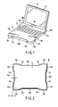
- FIG. 1 shows the construction of a mobile electronic appliance according to a first embodiment of the present invention.
- a notebook type personal computer as shown in FIG. 1, a PDA (personal digital assistant), etc. are known to the art as a mobile electronic appliance.
- a substantially rectangular box-shaped first casing 12 corresponding to a lid portion, which can be folded, is mounted to a second casing 13 corresponding to a substantially rectangular box-shaped base portion.
- the first casing 12 is mounted to the second casing 13 by a hinge mechanism 14 such that the first casing 12 can be folded to cover the upper surface of the second casing 13.
- a rectangular liquid crystal display section 11 is housed in the first casing 12 such that the liquid crystal display section 11 is protected by the peripheral frame of the first casing 12.
- a keyboard 15 is mounted on the second casing 13, and a precision unit 33 having a mechanical precision mechanism is housed in the second casing 13.
- the precision unit 33 includes, for example, a hard disk, a magnetic disk drive or an optical drive whose function may be possibly impaired by the impact from the outside.
- the first casing 12 constituting the lid portion of the personal computer is opened, and the keyboard mounted on the second casing 13 is operated.
- the first casing 12 is folded so as to cover the upper surface of the second casing 13.
- the entire personal computer comprising the first casing 12 and the second casing 13 assumes a substantially rectangular box-shaped state and is carried about under this particular state.
- the PDA (not shown) constituting a mobile electronic appliance is of the type that the lid portion is removed from the notebook type personal computer of the construction described above.
- the PDA is formed to have a rectangular box-shaped outer configuration like the notebook type personal computer in the state of carrying about the personal computer.
- a display section and an operating section are formed on the upper surface of the box-shaped casing 13. In the operating stage, a display screen displayed on the display section is touched, or the operating section is operated so as to switch the display screen.
- the PDA is carried about under the state that the screen display is turned off.
- swollen portions 16 that are swollen outward are formed in the four corner portions of the second casing 13, as shown in FIGS. 1, 2 and 3. These swollen portions 16 are formed integral with the second casing 13.
- the second casing 13 comprises a linear outer wall 13a corresponding to the side of the rectangular second casing 13, a swollen wall 13b corresponding to the corner portion of the rectangular second casing 13, and a sloped wall 13c connecting the linear outer wall 13a to the swollen wall 13b.
- the sloped wall 13c continuously extends outward from the linear outer wall 13a so as to bend the second casing 13, and the swollen wall 13b is formed contiguous to the sloped wall 13c.
- the swollen wall 13b is formed in substantially an L-shape in the plane parallel to the bottom of the second casing 13, so as to make roundish the corner portion of the second casing 13.
- the sloped wall 13b imparts a step A to the swollen wall 13b relative to the linear outer wall 13a so as to maintain a void state within the swollen corner portion 16.
- the step A for forming the void is defined to be not smaller than a braking distance ⁇ x required for a prescribed dropping height in order to absorb the impact in the dropping stage.
- the prescribed dropping height noted above is defined on the basis of JIS (Japanese Industrial Standards)-C0044 directed to the drop of an electronic appliance.
- the braking distance ⁇ x noted above implies the recessed amount (recessed distance) in the deformed portion of the second casing 13 included in the mobile electronic appliance when the mobile electronic appliance is allowed to drop from a prescribed height onto the ground so as to deform that portion of the second casing 13 which impinges on the ground.
- the braking distance ⁇ x implies the amount of deformation (recession) of the second casing 13 that permits absorbing the impact.
- the mobile electronic appliance since the mobile electronic appliance can be carried about, it is also possible to define the braking distance ⁇ x on the basis of the height of the electronic appliance when the electronic appliance is carried about, which is derived from the average height of the user. For example, it is possible for the braking distance ⁇ x to be defined on the basis that the height of the electronic appliance when the electronic appliance is carried out is set at 65 to 70 cm, more strictly, at 70 cm. Also, since the mobile electronic appliance is used in general on a desk, it is possible for the braking distance ⁇ x to be defined on the basis of the height of the general office desk or the height of the dining table. Where the braking distance ⁇ x is defined on the basis of the height of the desk, the height of the desk is set similarly at 65 to 70 cm, more strictly at 70 cm.
- the linear outer wall 13a, the swollen wall 13b and the sloped wall 13c, which collectively form the second casing 13, are set substantially equal to each other in thickness "t".
- the impact is imparted to the side surface of the second casing 13 in accordance with the posture of the second casing 13 in the dropping stage.
- the posture of the second casing 13 in the dropping stage is not constant, the impact given from, for example, the floor surface is mostly imparted to any of the swollen corner portions 16.
- the direction of the impact given to the swollen corner portions 16 is not constant such that the impact is imparted in various directions in accordance with the posture of the second casing 13.
- the colliding region including the swollen wall 13b and the sloped wall 13c, in which the collision takes place is deformed within the void section corresponding to the step A, the impact is absorbed within the colliding region so as to protect the parts housed in the second casing 13 from the impact. Also, the swollen corner portion 16, even if deformed, can be brought back to the original shape relatively easily unless the impact is so strong as to break the swollen corner portion 16 or that the applied impact remains inside the elastic region of the swollen corner portion 16.
- a linear side surface of the first casing 12 positioned to face the second casing 13 is arranged inside the swollen corner portion 16, which extends outward in each of the four corner portions, of the second casing 13.
- the linear side surface 17 of the first casing 12 is caused to abut against, for example, the floor.
- the impact imparted to the linear side surface 17 of the first casing 12 is sufficiently small, compared with the impact.
- the linear side surface 17 of the first casing 12 substantially constitutes a non-collision region to which the impact is not imparted. It follows that it is possible to protect the liquid crystal display section 11 housed in the first casing 12 from the impact.
- FIG. 4A shows the state of the one freedom spring model before the dropping
- FIG. 4B shows the state of the one freedom spring model after application of the impact.
- the mass "m" of the mobile electronic appliance is regarded as the mass point, and the deformation in the colliding region is represented by a linear spring. If the dropping height is denoted by h [m] and the gravitational acceleration is denoted by g [m/s 2 ], the speed at the colliding stage with the floor is represented by formula (1) given below, and the braking distance ⁇ x until the speed of the mass point is lowered to reach the value represented by formula (2) given below is represented by formula (4) given below.
- the dropping height given in Table B in the appendix of JIS-C0044 is 1 meter.
- the dropping height of 1.22 [m] is required in the MIL standards (MIL-STD-810F-516.5).
- the dropping height [h] is assumed to be 1 [m]
- critical acceleration allowable for the electronic part housed in the mobile electronic appliance is assumed to be 1,000 [G], which is equal to 9,800 m/s 2
- the required braking distance ⁇ x is 0.002 [m].
- the step A for forming the void noted above is at least 0.002 [m].
- the step A is set at a value not smaller than 0.002 [m] as long as the design of the second casing 13 is not impaired.
- the generated acceleration is lower than the critical acceleration of the part housed in the second casing 13.
- the acceleration exceeding the critical acceleration of the part housed in the second casing 13 is generated so as to cause an inconvenience in the operation of the mobile electronic appliance.
- FIG. 5 is a graph showing the impact characteristics A imparted to the electronic unit included in the mobile electronic appliance shown in FIGS. 2 and 3 and the impact characteristics B imparted to the electronic unit included in the mobile electronic appliance for the comparative case in which the swollen corner portion 16 is not included.
- the acceleration is plotted on the ordinate, and time is plotted on the abscissa.
- the curve showing the impact characteristics B of the mobile electronic appliance including the second casing 13 in which the swollen corner portion 16 is not included has a peak value Gb of the first acceleration, and the acceleration acting time in this case is denoted by Tb in FIG. 5.
- the curve showing the impact characteristics A of the mobile electronic appliance including the second casing 13 having the swollen corner portion 16 has a peak value Ga of the first acceleration, and the acceleration acting time in this case is denoted by Ta. If the peak value Gb of the first acceleration and the acceleration acting time Tb for the impact characteristics B are compared with the peak value Ga of the first acceleration and the acceleration acting time Ta for the impact characteristics A, it can be understood that the acceleration acting time is prolonged so as to lower the peak value of the acceleration of the second casing 13 having the swollen corner portion 16 because the swollen corner portion is deformed in the colliding stage. As apparent from the comparison between curves A and B shown in FIG.
- a swollen corner portion having an inner void space is formed in the second casing 13 of the mobile electronic appliance shown in FIGS. 2 and 3 on the assumption that the mobile electronic appliance is carried about by the user.
- the particular measure is taken due to the possibility of the mobile electronic appliance being dropped to, for example, the ground while the mobile electronic appliance is being carried about.
- the mobile electronic appliance according to the first embodiment of the present invention is not formed to present a simple rectangular configuration. Since the swollen corner portions are formed in the second casing 13, the side portions of the rectangular configuration are substantially recessed. It follows that the mobile electronic appliance is held by the user at the recessed side portions. Since the recessed side portions are held by the user, the mobile electronic appliance can be carried about without fail. In other words, the mobile electronic appliance of the particular shape produces an additional effect of preventing the mobile electronic appliance from being dropped erroneously to, for example, the ground.
- a mobile electronic appliance according to a modified embodiment of the present invention will now be described with reference to FIGS. 6 to 9.
- those portions of the mobile electronic appliance which are equal to the portions of the mobile electronic appliance described above are denoted by the same reference numerals so as to avoid the overlapping description.
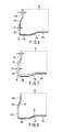
- FIG. 6 is a partial cross sectional view schematically showing in a broken fashion the construction of a single corner portion of the second casing 13 included in the mobile electronic appliance according to another embodiment of the present invention.
- the thickness Ta of each of the swollen wall 13b and the sloped wall 13c of the second casing 13 is set smaller than the thickness "t" of the linear outer wall 13a of the second casing 13.
- the second casing 13 is formed of a metallic material having a large Young's modulus, it is effective to decrease the thickness of the swollen corner portion 16 because the rigidity in each of the four corner portions is lowered so as to increase the amount of deformation of the swollen corner portion in the colliding stage. As a result, it is possible to improve the impact absorbing capability of the swollen corner portion 16.
- FIG. 7 is a partial cross sectional view schematically showing in a broken fashion the construction of a single corner portion of the second casing 13 included in the mobile electronic appliance according to another modified embodiment of the present invention.
- the thickness Tb of each of the swollen wall 13b and the sloped wall 13c is set larger than the thickness "t" of the linear outer wall 13a of the second casing 13.
- the second casing 13 is formed of a resin material having a small Young's modulus and a low tensile strength, it is possible to increase the rigidity of each of the four corner portions of the second casing 13 by increasing the thickness of the swollen corner portion 16. It follows that it is possible to prevent the swollen corner portion 16 from being broken while maintaining the effect of absorbing the impact, i.e., the effect produced by the deformation of the swollen corner portion 16 in the colliding stage.
- FIG. 8 is a partial cross sectional view schematically showing in a broken fashion a single corner portion of the second casing 13 included in the mobile electronic appliance according to still another modified embodiment of the present invention.
- At least one through-hole 18 is formed in the sloped portion of the second casing 13 so as to improve the effect of absorbing the impact.
- the rigidity of the sloped portion is lowered by the presence of the hole 18 so as to make it possible to increase the deformation of the swollen portion in the colliding stage. As a result, it is possible to improve the impact absorption effect.
- the swollen corner portion 16 is formed in the second casing 13 alone.
- the swollen corner portions 20 formed in the first casing 12 are constructed like the swollen corner portions 16 of the second casing 13 such that a swollen wall 12b is formed contiguous to a linear outer wall 12a with a sloped wall 12c interposed therebetween in a manner to have a void region formed in the swollen wall 12b.
- the first casing 12 including the swollen corner portions 20 is sized smaller than the second casing 13 including the swollen corner portions 16.
- a peripheral region 22 in the upper surface of the second casing 13 protrudes outside the periphery of the first casing 12.
- the first casing 12 and the second casing 13 are arranged such that the circumferential side surface of the second casing 13 is positioned outside the circumferential side surface of the first casing 12.
- the particular construction described above is advantageous in the case where the mobile electronic appliance is erroneously dropped from the side surface onto, for example, the ground when the mobile electronic appliance is being carried about.
- the mobile electronic appliance is erroneously dropped from the side surface onto, for example, the floor
- the circumferential side surface of the second casing 13 extruding outward from the circumferential side surface of the first casing 12 is brought into contact first with, for example, the floor surface.
- the contact region is limited mainly to the swollen corner portion 16 of the second casing 13, the impact is absorbed mainly in the swollen corner portion 16.
- the weight of the electronic unit housed in the second casing 13 is larger than the weight of, for example, the liquid crystal display section 11 housed in the first casing 12.
- the second casing 13 it is highly possible for the second casing 13 to be brought into contact first with, for example, the floor surface, compared with the first casing 12. It follows that, when the mobile electronic appliance is dropped onto, for example, the floor, the impact is absorbed first by the swollen corner portion 16 of the second casing 13 and, then, the first casing 12 abuts against, for example, the floor surface.
- each of the embodiments described above is directed to the case where the mobile electronic appliance is dropped from the side surface onto, for example, the floor.
- the mobile electronic appliance is not necessarily dropped from the side surface onto, for example, the floor while the mobile electronic appliance is being carried about. It is possible for the mobile electronic appliance to be dropped from the back surface onto, for example, the floor. It is also possible for the mobile electronic appliance to be dropped from the side surface onto, for example, the floor and, then, to be rebounded such that the impact is applied to the bottom surface of the mobile electronic appliance.
- FIG. 10 is an oblique view schematically showing the back surface of the mobile electronic appliance according to another embodiment of the present invention, in which the second casing 13 is provided with a pair of extended projections 34 each having a stripe or band shape on the bottom surface in addition to the swollen corner portions 16.
- Projections consisting of a flexible material such as rubber, i.e., supporting pads 35, are formed in the four corner portions of a bottom surface 31a of the second casing 13. These projections act as support sections in the stage of disposing the electronic appliance on a flat surface such as a desk so as to prevent the bottom surface from being brought into direct contact with the disposing surface, thereby making it possible to dispose stably the electronic appliance on the flat surface.
- a precision unit 33 housed in the second casing 13 is formed in general in a manner to have a slim rectangular box-like outer shape.
- the precision unit 33 is fixed with, for example, a screw to the side wall section of the second casing 13 by utilizing a support frame (not shown).
- the precision unit 33 is supported by the support mechanism within the second casing 13 via the support frame in a manner to form a small gap G between the inner bottom section of the precision unit 33 and the bottom surface of the second casing 13 as shown in FIG. 11.
- a pair of the extended projections 34 which have a height substantially equal to or larger than the height of the support pad 35, are formed to extend in parallel along the outer bottom surface of the second casing 13.
- the extended projections 34 it is possible for the extended projections 34 to be formed integral with the second casing 13 by using a material similar to that of the second casing 13.
- the extended projections 34 it is also possible for the extended projections 34 to be formed of a material differing from the material of the second casing 13 and having buffer properties like the support pad 35 so as to be fixed by gluing to the bottom surface of the second casing 13.
- the pair of the extended projections 34 are arranged outside the mutually facing both sides 36 of a substantially rectangular region 32 that is defined when the precision unit 33 is projected by the planar projection method on the bottom surface 31a of the second casing 13. Also, the extended projections 34 extend along the both sides 36 noted above. Incidentally, the rectangular region 32 noted above is shaded in FIG. 10.
- the extended projections 34 are arranged on the bottom surface 31a of the second casing 13 such that the center line of these extended projections 34 is coincident with a center line 38 passing through the geometric center of the substantially rectangular region 32, the center line 38 extending substantially in parallel to the side wall to which the precision unit 33 is fixed.
- the extended projections 34 having stripe or band shape are arranged in symmetry with respect to the center line 38.
- the extended projection 36 has a length not smaller than half the length of the side 36 along the extended projection 34.
- the extended projection 34 has a length substantially equal to that of the side 36 along the extended projection 34 or slightly larger than the length of the side 36.
- the extended projection 34 has a length substantially equal to the length of the side 36 along the extended projection 34 or a length larger than the length of the side 36.
- the extended projections 34 are allowed to collide against the floor simultaneously with the collision of the support pads 35 against the floor or slightly after the support pads 35 are allowed to collide against the floor.
- the slight delay in the collision of the support pads 35 against the floor noted above is negligible, and the extended projections 34 and the support pad 35 can be regarded as colliding against the floor simultaneously.
- the presence of the extended projections 34 permits preventing the bottom surface 31a of the second casing 13, particularly, the substantially rectangular region 32 of the bottom surface 31a on which is disposed the precision unit 33 that is heavy compared with the other part, from being brought into direct contact with the floor surface.
- the pair of the extended projections 34 and the bottom surface region corresponding to the substantially rectangular region 32 that is held between the extended projections 34 perform the function of a frame of a rigid structure so as to prevent the entire bottom surface 31a from being warped.
- tension is imparted by the impact given to the extended projections 34 to the bottom surface of the substantially rectangular region 32 that is held between the pair of the extended projections 34.
- the rigidity of the bottom surface of the substantially rectangular region 32 is increased compared with the ordinary state so as to permit the frame of the rigid structure to protect the precision unit 33 without fail.
- the impact imparted to the frame of the rigid structure is dispersed over the entire second casing 13 so as to make it possible to prevent a big impact from acting directly on the precision unit 33.
- the amount of the bending warp is lowered in the rectangular region 32 that is held between the pair of the extended projections 34 because the height of extended projection 34 is increased and the distance between the support points is decreased. It follows that it is possible to avoid the collision of the rectangular region 32 against the floor surface.
- the precision unit 33 positioned right above the rectangular region 32 is unlikely to receive directly the impact force from the floor surface via the bottom surface 31a of the second casing 13.
- the extended projections 34 are arranged in symmetry with respect to the geometric center line 38 as described previously. As a result, the impact applied to the extended projections 34 is dispersed relatively uniformly in the precision unit 33 via the extended projections 34 so as to make it possible to prevent the impact from being concentrated on a specified point.
- the precision unit 33 is moved simultaneously with the collision of the support pads 35 against the floor so as to cause the entire bottom surface 31a to be warped. Also, the rectangular region 32 having a heavy article disposed thereon is dropped toward the floor simultaneously with the drop of the second casing 13 onto the floor. It follows that the impact is applied directly to the precision unit 33.
- the extended projections 34 of band or stripe shape are arranged outside the both sides 36 of the substantially rectangular region 32 that is defined when the precision unit 33 is projected by the planar projection method onto the bottom surface 31a of the second casing 13. It is necessary for the extended projections 34 to be arranged outside the both sides 36 of the rectangular region 32, and it is undesirable for the extended projections 32 to be arranged on the rectangular region 32. Where the extended projections 34 are arranged on the rectangular region 32, the bottom surface of the rectangular region 32 is warped so as to cause the impact to be applied directly to the precision unit 33. The particular difficulty is equal to that in the case where the extended projections 34 are not arranged.
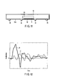
- FIG. 12 is a graph showing the impact characteristics C imparted to the electronic unit included in the mobile electronic appliance in which the extended projections 34 are arranged outside the both sides 36 of the substantially rectangular region 32 as shown in FIG. 10 and also showing the impact characteristics D imparted to the electronic unit included in the comparative mobile electronic appliance in which the extended projections 34 are not arranged.
- the acceleration is plotted on the ordinate, and time is plotted on the abscissa.
- a big acceleration is imparted to the electronic unit immediately after the drop of the second casing onto, for example, the floor as seen from curve D shown in FIG. 12.
- the first to third accelerations are imparted to the electronic unit in a time-divided fashion.
- a big impact is not imparted to the electronic unit in the case where the extended projections 34 are formed on the bottom surface of the second casing 13.
- the impact is dispersed and is moderately attenuated. It follows that, according to the construction shown in FIG. 9, it is possible to protect without fail the electronic unit housed in the casing from the impact.
- each of the pair of the extended projections 34 is divided into two segments 34a and 34b, as shown in FIG. 13.
- stripe segments 34a, 34b of the extended projection 34 are arranged outside the both sides 36 of the substantially rectangular region 32. These stripe segments 34a, 34b are arranged in symmetry with respect to the center line 38, and are separated from each other by the gap through which extends the center line 38.
- the stripe segments 34a, 34b extend along the both sides 36 of the substantially rectangular region 32 as in the construction shown in FIG. 9.
- the stripe segments 34a, 34b are substantially equal to each other in width.
- the sum of the lengths of the stripe segments 34a and 34b that are linearly arranged is substantially equal to or larger than the length of the side 36 of the substantially rectangular region 32 along which the extended projection 34 extends.
- the stripe segments 34a, 34b are linearly arranged, and it is possible to arrange, for example, a screw hole in the gap between the stripe segments 34a and 34b. Also, it is apparent that it is not absolutely necessary for the extended projection 34 to be separated into two stripe segments 34a, 34b. It is also possible for the extended projection 34 to be separated into three or more stripe segments and for the separated stripe segments to be arranged linearly.
- the extended projections 34 are arranged to extend along the both sides 36 corresponding to the longer sides of the substantially rectangular region 32.
- extended projections 34e in a manner to extend along the mutually facing longer sides 36a of the substantially rectangular region 32 and to arrange extended projections 34f in a manner to extend along the mutually facing shorter sides 36b of the substantially rectangular region 32, as shown in FIG. 14.
- the substantially rectangular region 32 extends to reach the side wall of the second casing 13.
- the extended projection 34f extending along the shorter side 36b positioned close to the side wall to be arranged within the substantially rectangular region 32 or not to be arranged at all.
- the extended projection 34f is arranged on the bottom surface 31a of the second casing 13.
- the extended projection 34f is possible to arrange the extended projection 34f on the side surface 13a of the second casing 13 or on the upper surface within the second casing 13, not on the bottom surface 31a of the second casing 13.
- the bottom surface 31a corresponding to the substantially rectangular region 32 are supported by the extended projections 34, 34e and 34f extending along the shorter sides and the longer sides of the substantially rectangular region 32.
- the construction shown in FIG. 14 can have a rigidity higher than that of the construction shown in FIG. 8.
- the impact can be dispersed more effectively in the construction shown in FIG. 14. It follows that it is possible to protect the electronic unit 33 housed in the second casing 13 from the external impact more effectively.
- the extended projections 34e, 34f or the stripe segments 34a, 34b may be formed integral with the second casing 13 as shown in FIG. 11. It is possible for the extended projections 34e, 34f or the stripe segments 34a, 34b to be solid or to be hollow or recessed as shown in FIG. 15. Further, it is possible for the extended projections 34, 34e, 34f or the stripe segments 34a, 34b to be formed of a different material such as a rubber-series resin, a plastic material, or a metal. Still further, it is possible for the extended projections 34, 34e, 34f or the stripe segments 34a, 34b to be bonded or fixed to the second casing 13, as shown in FIG. 16.
- the mobile electronic appliance according to the present invention makes it possible to improve the impact resistance when the mobile electronic appliance is dropped onto the floor or the ground.
- the mobile electronic appliance of the present invention makes it possible to decrease the weight and to lower the manufacturing cost while maintaining a sufficient impact resistance.
Landscapes
- Engineering & Computer Science (AREA)
- Theoretical Computer Science (AREA)
- Computer Hardware Design (AREA)
- Physics & Mathematics (AREA)
- General Engineering & Computer Science (AREA)
- General Physics & Mathematics (AREA)
- Human Computer Interaction (AREA)
- Mathematical Physics (AREA)
- Computing Systems (AREA)
- Casings For Electric Apparatus (AREA)
- Telephone Set Structure (AREA)
Applications Claiming Priority (2)
| Application Number | Priority Date | Filing Date | Title |
|---|---|---|---|
| JP2003400828A JP4080990B2 (ja) | 2003-11-28 | 2003-11-28 | 携帯型電子装置 |
| JP2003400828 | 2003-11-28 |
Publications (2)
| Publication Number | Publication Date |
|---|---|
| EP1555594A1 true EP1555594A1 (de) | 2005-07-20 |
| EP1555594B1 EP1555594B1 (de) | 2013-01-23 |
Family
ID=34616675
Family Applications (1)
| Application Number | Title | Priority Date | Filing Date |
|---|---|---|---|
| EP04257344A Expired - Lifetime EP1555594B1 (de) | 2003-11-28 | 2004-11-26 | Mobiles elektronisches Gerät |
Country Status (5)
| Country | Link |
|---|---|
| US (1) | US7106580B2 (de) |
| EP (1) | EP1555594B1 (de) |
| JP (1) | JP4080990B2 (de) |
| KR (1) | KR100760224B1 (de) |
| CN (1) | CN100414476C (de) |
Cited By (3)
| Publication number | Priority date | Publication date | Assignee | Title |
|---|---|---|---|---|
| US8797734B2 (en) | 2007-12-17 | 2014-08-05 | Fujitsu Limited | Electronic apparatus |
| EP2985983A1 (de) * | 2014-08-12 | 2016-02-17 | Samsung Electronics Co., Ltd. | Gehäuse, herstellungsverfahren dafür und elektronische vorrichtung mit dem gehäuse |
| US10869397B2 (en) | 2018-06-04 | 2020-12-15 | Samsung Electronics Co., Ltd | Housing including ceramic composition and electronic device including the housing |
Families Citing this family (32)
| Publication number | Priority date | Publication date | Assignee | Title |
|---|---|---|---|---|
| US20040066618A1 (en) * | 2002-08-01 | 2004-04-08 | Layton Michael R. | Shock-resistant enclosure |
| US7232960B2 (en) * | 2004-12-21 | 2007-06-19 | Kabushiki Kaisha Toshiba | Apparatus for improving durability of electronic devices |
| JP2007052616A (ja) * | 2005-08-17 | 2007-03-01 | Hitachi Metals Ltd | 電子機器用筐体およびその製造方法 |
| US7586739B2 (en) * | 2006-07-31 | 2009-09-08 | Lenovo (Singapore) Pte. Ltd. | Arrangements for averting flat panel display damage |
| JP5076538B2 (ja) * | 2007-02-16 | 2012-11-21 | ヤマハ株式会社 | 音響調節器の筐体構造 |
| JP5082485B2 (ja) * | 2007-02-16 | 2012-11-28 | ヤマハ株式会社 | 音響調節器の筐体構造 |
| JP2009146269A (ja) * | 2007-12-17 | 2009-07-02 | Fujitsu Ltd | 表示装置および電子機器 |
| JP2009146270A (ja) * | 2007-12-17 | 2009-07-02 | Fujitsu Ltd | 電子機器 |
| US8014148B2 (en) * | 2008-02-28 | 2011-09-06 | Panasonic Corporation | Electronic device |
| GB2474144B (en) * | 2008-07-25 | 2012-11-14 | Hewlett Packard Development Co | Leakage current dissipation devices |
| JP2010049351A (ja) * | 2008-08-19 | 2010-03-04 | Panasonic Corp | 情報処理装置 |
| US20100094899A1 (en) * | 2008-09-30 | 2010-04-15 | Yahoo! Inc. | System for assembling and providing problem solving frameworks |
| JP4891980B2 (ja) * | 2008-12-11 | 2012-03-07 | 株式会社東芝 | 電子機器 |
| JP5415200B2 (ja) | 2009-09-28 | 2014-02-12 | パナソニック株式会社 | 情報処理装置 |
| US8411432B1 (en) * | 2009-12-02 | 2013-04-02 | Dell Products, Lp | System, apparatus and method for tiered shock solution |
| US8576561B2 (en) * | 2010-02-02 | 2013-11-05 | Apple Inc. | Handheld device enclosure |
| JP4865052B2 (ja) * | 2010-04-20 | 2012-02-01 | 株式会社東芝 | 電子機器 |
| JP5066235B2 (ja) * | 2010-08-25 | 2012-11-07 | 株式会社東芝 | 電子機器 |
| JP2012093955A (ja) * | 2010-10-27 | 2012-05-17 | Kyocera Corp | 携帯型電子機器 |
| US8971974B2 (en) | 2011-04-28 | 2015-03-03 | Nflukz, Llc | Cover for hand-held electronic device |
| FR2981187B1 (fr) * | 2011-10-11 | 2015-05-29 | Franck Poullain | Tablette de communication pour l'enseignement |
| USD709510S1 (en) | 2012-02-29 | 2014-07-22 | Hatch, Inc. | Tablet cover |
| US10300658B2 (en) | 2012-05-03 | 2019-05-28 | Apple Inc. | Crack resistant plastic enclosure structures |
| US9288294B2 (en) * | 2012-10-19 | 2016-03-15 | Htc Corporation | Handheld electronic device and method for assembling display panel thereof |
| JP6044830B2 (ja) | 2012-12-27 | 2016-12-14 | パナソニックIpマネジメント株式会社 | 電子機器 |
| KR20140122433A (ko) * | 2013-04-10 | 2014-10-20 | 삼성디스플레이 주식회사 | 휴대 단말기 및 휴대 단말기의 형상 변형 방법 |
| CN105578821A (zh) * | 2014-10-13 | 2016-05-11 | 联想(北京)有限公司 | 电子设备及其壳体的制备方法 |
| JP2018025445A (ja) * | 2016-08-09 | 2018-02-15 | 矢崎エナジーシステム株式会社 | 膜式ガスメータ |
| WO2019087333A1 (ja) * | 2017-11-01 | 2019-05-09 | 株式会社Msソリューションズ | 携帯電子機器カバー |
| US11604374B2 (en) * | 2017-12-26 | 2023-03-14 | Saturn Licensing Llc | Display apparatus |
| US10466807B1 (en) * | 2018-11-13 | 2019-11-05 | Pioneer Square Brands, Inc. | Keyboard |
| TWM580846U (zh) * | 2019-04-09 | 2019-07-11 | 華碩電腦股份有限公司 | 手持式電子裝置之擴充外殼 |
Citations (5)
| Publication number | Priority date | Publication date | Assignee | Title |
|---|---|---|---|---|
| US5583742A (en) * | 1993-12-15 | 1996-12-10 | Alps Electric Co., Ltd. | Computer with protective cover having outwardly projecting cushioning portions |
| US20020043608A1 (en) * | 2000-06-01 | 2002-04-18 | Fujitsu Limited | Shock absorbing member capable of absorbing larger impact applied to electronic apparatus |
| US20020057813A1 (en) * | 1998-08-13 | 2002-05-16 | International Business Machines Corporation | Impact-resistant electronic device |
| US6498719B1 (en) * | 1999-12-10 | 2002-12-24 | Dell Usa, L.P. | Apparatus and method for reducing impact-induced shock and vibration in a portable computer |
| US20030179543A1 (en) * | 2002-03-25 | 2003-09-25 | International Business Machines Corporation | Deformable shock absorbing mechanism for a computer apparatus or a precision apparatus |
Family Cites Families (19)
| Publication number | Priority date | Publication date | Assignee | Title |
|---|---|---|---|---|
| US5291375A (en) | 1991-09-30 | 1994-03-01 | Kabushiki Kaisha Toshiba | Printed circuit board and electric device configured to facilitate bonding |
| JPH07110726A (ja) * | 1993-10-13 | 1995-04-25 | Hitachi Ltd | 情報処理装置 |
| JP2892265B2 (ja) | 1993-12-15 | 1999-05-17 | アルプス電気株式会社 | コンピュータ |
| US5706168A (en) * | 1995-07-07 | 1998-01-06 | Itronix Corporation | Impact-resistant notebook computer having hard drive mounted on shock-isolating mounting bridge and impact attenuating covering |
| JPH10322039A (ja) | 1997-05-14 | 1998-12-04 | Seiko Epson Corp | 電子機器の耐衝撃構造 |
| KR100303080B1 (ko) * | 1997-10-13 | 2001-11-22 | 윤종용 | 충격에강한휴대용컴퓨터 |
| JPH11353054A (ja) | 1998-06-10 | 1999-12-24 | Toshiba Corp | 液晶表示装置 |
| US6179122B1 (en) * | 1998-11-12 | 2001-01-30 | Michael L. Moncrief | Protective holder for a portable electronic device |
| JP2000148295A (ja) | 1998-11-12 | 2000-05-26 | Hitachi Ltd | コンピュータ装置 |
| TWI240592B (en) * | 1999-06-03 | 2005-09-21 | Koninkl Philips Electronics Nv | Organic electroluminescent device |
| JP2001026722A (ja) * | 1999-07-13 | 2001-01-30 | Yokohama Rubber Co Ltd:The | 携帯電子機器筐体 |
| US6519141B2 (en) * | 2000-05-12 | 2003-02-11 | Palm, Inc. | Handheld computer cover with deformable exterior |
| US20020085342A1 (en) * | 2000-12-29 | 2002-07-04 | Shin-Chen Chen | Portable computer with shockproof function |
| CN2525573Y (zh) * | 2001-10-23 | 2002-12-11 | 纬创资通股份有限公司 | 便携式电脑及其撞击缓冲装置 |
| JP4048349B2 (ja) | 2001-12-04 | 2008-02-20 | Nok株式会社 | 携帯型情報処理装置 |
| JP3673223B2 (ja) | 2002-01-21 | 2005-07-20 | 株式会社東芝 | 携帯用情報機器 |
| US6977809B2 (en) * | 2002-06-07 | 2005-12-20 | Jerald A. Bovino | Portable computer case |
| JP2004152116A (ja) | 2002-10-31 | 2004-05-27 | Toshiba Corp | 電子機器 |
| KR200326802Y1 (ko) | 2003-06-18 | 2003-09-17 | 정수용 | 휴대폰의 충격 완화구조 |
-
2003
- 2003-11-28 JP JP2003400828A patent/JP4080990B2/ja not_active Expired - Fee Related
-
2004
- 2004-11-24 US US10/995,180 patent/US7106580B2/en not_active Expired - Fee Related
- 2004-11-26 KR KR1020040097784A patent/KR100760224B1/ko not_active Expired - Fee Related
- 2004-11-26 EP EP04257344A patent/EP1555594B1/de not_active Expired - Lifetime
- 2004-11-26 CN CNB2004100973144A patent/CN100414476C/zh not_active Expired - Fee Related
Patent Citations (5)
| Publication number | Priority date | Publication date | Assignee | Title |
|---|---|---|---|---|
| US5583742A (en) * | 1993-12-15 | 1996-12-10 | Alps Electric Co., Ltd. | Computer with protective cover having outwardly projecting cushioning portions |
| US20020057813A1 (en) * | 1998-08-13 | 2002-05-16 | International Business Machines Corporation | Impact-resistant electronic device |
| US6498719B1 (en) * | 1999-12-10 | 2002-12-24 | Dell Usa, L.P. | Apparatus and method for reducing impact-induced shock and vibration in a portable computer |
| US20020043608A1 (en) * | 2000-06-01 | 2002-04-18 | Fujitsu Limited | Shock absorbing member capable of absorbing larger impact applied to electronic apparatus |
| US20030179543A1 (en) * | 2002-03-25 | 2003-09-25 | International Business Machines Corporation | Deformable shock absorbing mechanism for a computer apparatus or a precision apparatus |
Cited By (5)
| Publication number | Priority date | Publication date | Assignee | Title |
|---|---|---|---|---|
| US8797734B2 (en) | 2007-12-17 | 2014-08-05 | Fujitsu Limited | Electronic apparatus |
| EP2985983A1 (de) * | 2014-08-12 | 2016-02-17 | Samsung Electronics Co., Ltd. | Gehäuse, herstellungsverfahren dafür und elektronische vorrichtung mit dem gehäuse |
| US9699279B2 (en) | 2014-08-12 | 2017-07-04 | Samsung Electronics Co., Ltd | Housing, manufacturing method thereof, and electronic device including the housing |
| US10003679B2 (en) | 2014-08-12 | 2018-06-19 | Samsung Electronics Co., Ltd | Housing, manufacturing method thereof, and electronic device including the housing |
| US10869397B2 (en) | 2018-06-04 | 2020-12-15 | Samsung Electronics Co., Ltd | Housing including ceramic composition and electronic device including the housing |
Also Published As
| Publication number | Publication date |
|---|---|
| US20050130470A1 (en) | 2005-06-16 |
| CN1622000A (zh) | 2005-06-01 |
| KR100760224B1 (ko) | 2007-09-20 |
| JP4080990B2 (ja) | 2008-04-23 |
| EP1555594B1 (de) | 2013-01-23 |
| JP2005165475A (ja) | 2005-06-23 |
| US7106580B2 (en) | 2006-09-12 |
| KR20050052371A (ko) | 2005-06-02 |
| CN100414476C (zh) | 2008-08-27 |
Similar Documents
| Publication | Publication Date | Title |
|---|---|---|
| EP1555594B1 (de) | Mobiles elektronisches Gerät | |
| US6498719B1 (en) | Apparatus and method for reducing impact-induced shock and vibration in a portable computer | |
| US8797749B2 (en) | Electronic apparatus including bumper portion protecting housing | |
| US7420798B2 (en) | Portable microcomputer and display unit | |
| US11228334B2 (en) | Case structure | |
| KR101994889B1 (ko) | 휴대단말용 보호 장치 | |
| KR20210047753A (ko) | 디스플레이 보호 구조를 포함하는 폴더블 전자 장치 | |
| JP2013232892A (ja) | ディスプレイ装置の破損防止構造を備える携帯用端末機 | |
| US6021041A (en) | Tuned shock absorbing system for portable computer hard disc drives | |
| US7148418B2 (en) | Electronic device and holder having elastic elements thereof | |
| JP2013058883A (ja) | 衝撃緩衝部材および衝撃緩衝部材を備える携帯端末 | |
| CN213423800U (zh) | 电子设备 | |
| JP2003195773A (ja) | 平面型表示装置 | |
| JP6561705B2 (ja) | 情報処理装置 | |
| JP4149779B2 (ja) | 携帯型表示装置 | |
| JP2006201786A (ja) | プラズマディスプレイ装置 | |
| CN100524157C (zh) | 避震模块装置及数据处理系统 | |
| US8830670B2 (en) | Electronic device having mounting structure for hard disk drive | |
| CN221010463U (zh) | 一种防震动撞击的仪表保护壳 | |
| CN210605524U (zh) | 一种加固显示器 | |
| JP2005165480A (ja) | 携帯型電子装置 | |
| CN219202213U (zh) | 抗震防摔型工业显示屏 | |
| JP4900182B2 (ja) | 衝撃緩衝装置およびこの衝撃緩衝装置を有する情報処理装置 | |
| CN221804669U (zh) | 一种键盘 | |
| CN212365423U (zh) | 一种具有防碰撞功能的液晶显示屛 |
Legal Events
| Date | Code | Title | Description |
|---|---|---|---|
| PUAI | Public reference made under article 153(3) epc to a published international application that has entered the european phase |
Free format text: ORIGINAL CODE: 0009012 |
|
| 17P | Request for examination filed |
Effective date: 20041223 |
|
| AK | Designated contracting states |
Kind code of ref document: A1 Designated state(s): AT BE BG CH CY CZ DE DK EE ES FI FR GB GR HU IE IS IT LI LU MC NL PL PT RO SE SI SK TR |
|
| AX | Request for extension of the european patent |
Extension state: AL HR LT LV MK YU |
|
| AKX | Designation fees paid |
Designated state(s): DE FR GB |
|
| APBN | Date of receipt of notice of appeal recorded |
Free format text: ORIGINAL CODE: EPIDOSNNOA2E |
|
| APBR | Date of receipt of statement of grounds of appeal recorded |
Free format text: ORIGINAL CODE: EPIDOSNNOA3E |
|
| APAF | Appeal reference modified |
Free format text: ORIGINAL CODE: EPIDOSCREFNE |
|
| APAF | Appeal reference modified |
Free format text: ORIGINAL CODE: EPIDOSCREFNE |
|
| APAF | Appeal reference modified |
Free format text: ORIGINAL CODE: EPIDOSCREFNE |
|
| APBT | Appeal procedure closed |
Free format text: ORIGINAL CODE: EPIDOSNNOA9E |
|
| GRAP | Despatch of communication of intention to grant a patent |
Free format text: ORIGINAL CODE: EPIDOSNIGR1 |
|
| RIN1 | Information on inventor provided before grant (corrected) |
Inventor name: MUKAI, MINORU,C Inventor name: KUGIMIYA, TETSUYA,C Inventor name: KAWAMURA, NORIYASU,C |
|
| GRAS | Grant fee paid |
Free format text: ORIGINAL CODE: EPIDOSNIGR3 |
|
| GRAA | (expected) grant |
Free format text: ORIGINAL CODE: 0009210 |
|
| AK | Designated contracting states |
Kind code of ref document: B1 Designated state(s): DE FR GB |
|
| REG | Reference to a national code |
Ref country code: GB Ref legal event code: FG4D |
|
| REG | Reference to a national code |
Ref country code: DE Ref legal event code: R096 Ref document number: 602004040847 Country of ref document: DE Effective date: 20130321 |
|
| PLBE | No opposition filed within time limit |
Free format text: ORIGINAL CODE: 0009261 |
|
| STAA | Information on the status of an ep patent application or granted ep patent |
Free format text: STATUS: NO OPPOSITION FILED WITHIN TIME LIMIT |
|
| 26N | No opposition filed |
Effective date: 20131024 |
|
| REG | Reference to a national code |
Ref country code: DE Ref legal event code: R097 Ref document number: 602004040847 Country of ref document: DE Effective date: 20131024 |
|
| REG | Reference to a national code |
Ref country code: FR Ref legal event code: PLFP Year of fee payment: 12 |
|
| PGFP | Annual fee paid to national office [announced via postgrant information from national office to epo] |
Ref country code: GB Payment date: 20151125 Year of fee payment: 12 Ref country code: DE Payment date: 20151118 Year of fee payment: 12 |
|
| PGFP | Annual fee paid to national office [announced via postgrant information from national office to epo] |
Ref country code: FR Payment date: 20151008 Year of fee payment: 12 |
|
| REG | Reference to a national code |
Ref country code: DE Ref legal event code: R119 Ref document number: 602004040847 Country of ref document: DE |
|
| GBPC | Gb: european patent ceased through non-payment of renewal fee |
Effective date: 20161126 |
|
| REG | Reference to a national code |
Ref country code: FR Ref legal event code: ST Effective date: 20170731 |
|
| PG25 | Lapsed in a contracting state [announced via postgrant information from national office to epo] |
Ref country code: FR Free format text: LAPSE BECAUSE OF NON-PAYMENT OF DUE FEES Effective date: 20161130 |
|
| PG25 | Lapsed in a contracting state [announced via postgrant information from national office to epo] |
Ref country code: DE Free format text: LAPSE BECAUSE OF NON-PAYMENT OF DUE FEES Effective date: 20170601 Ref country code: GB Free format text: LAPSE BECAUSE OF NON-PAYMENT OF DUE FEES Effective date: 20161126 |