EP1555411A1 - Startsteuersystem für verbrennungsmotor - Google Patents
Startsteuersystem für verbrennungsmotor Download PDFInfo
- Publication number
- EP1555411A1 EP1555411A1 EP03809423A EP03809423A EP1555411A1 EP 1555411 A1 EP1555411 A1 EP 1555411A1 EP 03809423 A EP03809423 A EP 03809423A EP 03809423 A EP03809423 A EP 03809423A EP 1555411 A1 EP1555411 A1 EP 1555411A1
- Authority
- EP
- European Patent Office
- Prior art keywords
- internal combustion
- combustion engine
- cylinder
- output shaft
- start control
- Prior art date
- Legal status (The legal status is an assumption and is not a legal conclusion. Google has not performed a legal analysis and makes no representation as to the accuracy of the status listed.)
- Granted
Links
Images


Classifications
-
- F—MECHANICAL ENGINEERING; LIGHTING; HEATING; WEAPONS; BLASTING
- F02—COMBUSTION ENGINES; HOT-GAS OR COMBUSTION-PRODUCT ENGINE PLANTS
- F02N—STARTING OF COMBUSTION ENGINES; STARTING AIDS FOR SUCH ENGINES, NOT OTHERWISE PROVIDED FOR
- F02N99/00—Subject matter not provided for in the other groups of this subclass
- F02N99/002—Starting combustion engines by ignition means
- F02N99/006—Providing a combustible mixture inside the cylinder
-
- F—MECHANICAL ENGINEERING; LIGHTING; HEATING; WEAPONS; BLASTING
- F02—COMBUSTION ENGINES; HOT-GAS OR COMBUSTION-PRODUCT ENGINE PLANTS
- F02D—CONTROLLING COMBUSTION ENGINES
- F02D29/00—Controlling engines, such controlling being peculiar to the devices driven thereby, the devices being other than parts or accessories essential to engine operation, e.g. controlling of engines by signals external thereto
- F02D29/02—Controlling engines, such controlling being peculiar to the devices driven thereby, the devices being other than parts or accessories essential to engine operation, e.g. controlling of engines by signals external thereto peculiar to engines driving vehicles; peculiar to engines driving variable pitch propellers
-
- F—MECHANICAL ENGINEERING; LIGHTING; HEATING; WEAPONS; BLASTING
- F02—COMBUSTION ENGINES; HOT-GAS OR COMBUSTION-PRODUCT ENGINE PLANTS
- F02D—CONTROLLING COMBUSTION ENGINES
- F02D17/00—Controlling engines by cutting out individual cylinders; Rendering engines inoperative or idling
-
- F—MECHANICAL ENGINEERING; LIGHTING; HEATING; WEAPONS; BLASTING
- F02—COMBUSTION ENGINES; HOT-GAS OR COMBUSTION-PRODUCT ENGINE PLANTS
- F02D—CONTROLLING COMBUSTION ENGINES
- F02D41/00—Electrical control of supply of combustible mixture or its constituents
- F02D41/009—Electrical control of supply of combustible mixture or its constituents using means for generating position or synchronisation signals
-
- F—MECHANICAL ENGINEERING; LIGHTING; HEATING; WEAPONS; BLASTING
- F02—COMBUSTION ENGINES; HOT-GAS OR COMBUSTION-PRODUCT ENGINE PLANTS
- F02D—CONTROLLING COMBUSTION ENGINES
- F02D41/00—Electrical control of supply of combustible mixture or its constituents
- F02D41/02—Circuit arrangements for generating control signals
- F02D41/04—Introducing corrections for particular operating conditions
- F02D41/06—Introducing corrections for particular operating conditions for engine starting or warming up
- F02D41/062—Introducing corrections for particular operating conditions for engine starting or warming up for starting
-
- F—MECHANICAL ENGINEERING; LIGHTING; HEATING; WEAPONS; BLASTING
- F02—COMBUSTION ENGINES; HOT-GAS OR COMBUSTION-PRODUCT ENGINE PLANTS
- F02B—INTERNAL-COMBUSTION PISTON ENGINES; COMBUSTION ENGINES IN GENERAL
- F02B2275/00—Other engines, components or details, not provided for in other groups of this subclass
- F02B2275/16—Indirect injection
-
- F—MECHANICAL ENGINEERING; LIGHTING; HEATING; WEAPONS; BLASTING
- F02—COMBUSTION ENGINES; HOT-GAS OR COMBUSTION-PRODUCT ENGINE PLANTS
- F02D—CONTROLLING COMBUSTION ENGINES
- F02D41/00—Electrical control of supply of combustible mixture or its constituents
- F02D41/02—Circuit arrangements for generating control signals
- F02D41/04—Introducing corrections for particular operating conditions
- F02D41/042—Introducing corrections for particular operating conditions for stopping the engine
-
- F—MECHANICAL ENGINEERING; LIGHTING; HEATING; WEAPONS; BLASTING
- F02—COMBUSTION ENGINES; HOT-GAS OR COMBUSTION-PRODUCT ENGINE PLANTS
- F02N—STARTING OF COMBUSTION ENGINES; STARTING AIDS FOR SUCH ENGINES, NOT OTHERWISE PROVIDED FOR
- F02N19/00—Starting aids for combustion engines, not otherwise provided for
- F02N19/005—Aiding engine start by starting from a predetermined position, e.g. pre-positioning or reverse rotation
- F02N2019/007—Aiding engine start by starting from a predetermined position, e.g. pre-positioning or reverse rotation using inertial reverse rotation
-
- Y—GENERAL TAGGING OF NEW TECHNOLOGICAL DEVELOPMENTS; GENERAL TAGGING OF CROSS-SECTIONAL TECHNOLOGIES SPANNING OVER SEVERAL SECTIONS OF THE IPC; TECHNICAL SUBJECTS COVERED BY FORMER USPC CROSS-REFERENCE ART COLLECTIONS [XRACs] AND DIGESTS
- Y02—TECHNOLOGIES OR APPLICATIONS FOR MITIGATION OR ADAPTATION AGAINST CLIMATE CHANGE
- Y02T—CLIMATE CHANGE MITIGATION TECHNOLOGIES RELATED TO TRANSPORTATION
- Y02T10/00—Road transport of goods or passengers
- Y02T10/10—Internal combustion engine [ICE] based vehicles
- Y02T10/12—Improving ICE efficiencies
Definitions
- the present invention relates to an internal combustion engine mounted on an a vehicle or the like, and in particular to a start control technology for an internal combustion engine
- an electric motor is generally used as means for rotationally driving (i.e. cranking) a crankshaft upon starting an internal combustion engine. It is necessary for such an electric motor to rotationally drive the crankshaft while resisting a gas compression force or frictions generated in various portions of the internal combustion engine. Hence, the electric motor tends to have high rated performance and power consumption of the electric motor also tends to become large accordingly.
- An object of the present invention is to provide a technology that enables efficient starting of a port injection type internal combustion engine.
- a start control apparatus for an internal combustion engine comprises:
- the most significant feature of this invention is that in an internal combustion engine equipped with a fuel injection valve(s) for injecting fuel into an intake passage, when a condition for stopping the driving of the internal combustion engine is met, the operation of an ignition plug(s) is suspended while the operation of the fuel injection valve(s) is continued to stop the driving of the internal combustion engine, and to seal unburned fuel in the cylinder that is in the expansion stroke upon stoppage of the internal combustion engine, and upon starting the internal combustion engine subsequently, the fuel in the interior of the aforementioned cylinder is burned so that the internal combustion engine is started utilizing the pressure generated upon combustion of the fuel.
- the ignition suspending means suspends the operation of only the ignition plug.
- the start control means caises the ignition plug of the expansion stroke cylinder upon stoppage to operate to burn the unburned air fuel mixture sealed in the expansion stroke cylinder upon stoppage.
- the ignition suspending means may be adopted to once suspend the operation of the ignition plug and the operation of the fuel injection valve when a requirement for stopping the driving of the internal combustion engine arises and to operate only the fuel injection valve again just before rotation of the engine output shaft of the internal combustion engine stops.
- the start control means may be adapted to start the internal combustion engine forcibly in case that driving stop time of the internal combustion engine becomes longer than a predetermined time period.
- a start control apparatus for an internal combustion engine according to the present invention may comprise:
- the most significant feature of this invention is that in an internal combustion engine equipped with a fuel injection valve(s) for injecting fuel into an intake passage, the cylinder that will be on the expansion stroke upon stoppage of the internal combustion engine is estimated and fuel is supplied to that cylinder in advance just before the driving of the internal combustion engine stops, and upon starting the internal combustion engine subsequently, the fuel in the interior of that cylinder is burned so as to start the internal combustion engine utilizing the pressure generated thereby.
- the driving stop means suspends the operation of the ignition plug and the operation of the fuel combustion valve when the driving stop condition for the internal combustion engine is met. Once the operation of the ignition plug and the fuel injection valve is suspended, the rotation of the engine output shaft is gradually slowed down.
- the estimate means estimates the cylinder that will be on its expansion stroke when the rotation of the engine output shaft stops (such a cylinder will be referred to as the expansion stroke cylinder upon stoppage hereinafter). Subsequently, the fuel injection control means causes the fuel injection valve of the aforementioned expansion stroke cylinder upon stoppage to operate just before the rotation of the engine output shaft stops.
- the fuel injected from the aforementioned fuel injection valve into the intake passage is taken into the expansion stroke cylinder upon stoppage together with air in the intake passage to form air-fuel mixture while the expansion stroke cylinder upon stoppage is on the intake stroke. Subsequently, the rotation of the engine output shaft stops when the expansion stroke cylinder upon stoppage gets on the expansion stroke after undergoing the compression stroke.
- the start control means Upon the next start of the internal combustion engine, the start control means causes the ignition plug of the expansion stroke cylinder upon stoppage to operate so that the unburned air-fuel mixture in the interior of the expansion stroke cylinder upon stoppage is burned.
- the start control apparatus for an internal combustion engine may be provided with output shaft rotating means for rotating, in case that rotation of the engine output shaft stops before the expansion stroke cylinder upon stoppage gets on the expansion stroke, the engine output shaft until the expansion stroke cylinder upon stoppage gets on the expansion stroke.
- This output shaft rotating means may be adapted to rotate, upon stoppage of the driving of the internal combustion engine (for example when the rotation of the engine output shaft stops), the engine output shaft until the expansion stroke cylinder upon stoppage gets on the expansion stroke, or alternatively to rotate the engine output shaft until the expansion stroke cylinder upon stoppage gets on the expansion stroke upon the next start of the internal combustion engine.
- the start control means may be adapted to cause the ignition plug of the expansion stroke cylinder upon stoppage to operate at the time when the aforementioned expansion stroke cylinder upon stoppage gets on the expansion stroke.
- the engine output shaft is rotated until the expansion stroke cylinder upon stoppage gets on the expansion stroke, although it is necessary to cause a starter apparatus such as a starter motor or a motor generator to operate, the operating time thereof is very short.
- the air-fuel mixture in the interior of the expansion stroke cylinder upon stoppage is burned at the time when the expansion stroke cylinder upon stoppage gets on the expansion stroke, and the combustion pressure generated thereby acts to rotate the engine output shaft. Consequently, the load applied on the starter apparatus is reduced after the expansion stroke cylinder upon stoppage shifts from the compression stroke to the expansion stroke.
- the estimate means may be adapted to estimate the cylinder that is on the compression stroke when the rotation of the engine output shaft of the internal combustion engine stops (which will be referred to as the compression stroke cylinder upon stoppage hereinafter) instead of the expansion stroke cylinder upon stoppage.
- the fuel injection control means causes to fuel injection valve of the cylinder that is estimated by the estimate means to operate again just before the rotation of the engine output shaft of the internal combustion engine stops.
- the output shaft rotating means rotates the engine output shaft until the cylinder estimated by the estimate means gets on the expansion stroke.
- the start control means causes the ignition plug of the compression stroke cylinder upon stoppage to operate, when the start condition for the internal combustion engine is met.
- the load applied on the starter apparatus such as a starter motor or a motor generator is reduced.
- the start control means may be adapted to start the internal combustion engine forcibly in case that the driving stop time of the internal combustion engine becomes longer than a predetermined time period.
- the start control apparatus for an internal combustion engine may be adapted in such a way that the estimate means estimates the cylinder that will be on the compression stroke upon stoppage of the rotation of the engine output shaft (which will be referred to as the compression stroke cylinder upon stoppage hereinafter) in addition to the cylinder that will be on the expansion stroke (i.e. the expansion stroke cylinder upon stoppage), and the fuel injection control means causes the fuel injection valve of the compression stroke cylinder upon stoppage and the fuel injection valve of the expansion stroke cylinder upon stoppage to operate just before the stoppage of the rotation of the engine output shaft so as to seal unburned air-fuel mixture in the interior of the compression stroke cylinder upon stoppage and the expansion stroke cylinder upon stoppage.
- the estimate means estimates the cylinder that will be on the compression stroke upon stoppage of the rotation of the engine output shaft (which will be referred to as the compression stroke cylinder upon stoppage hereinafter) in addition to the cylinder that will be on the expansion stroke (i.e. the expansion stroke cylinder upon stoppage)
- the start control means may cause the ignition plug of the expansion stroke cylinder upon stoppage to operate firstly to rotate the engine output shaft, and subsequently cause the ignition plug of the compression stroke cylinder upon stoppage to operate at the time when the compression stroke cylinder upon stoppage gets on the expansion stroke.
- a start control apparatus for an internal combustion engine according to the present invention may comprise:
- the most significant feature of this invention is that in an internal combustion engine equipped with a fuel injection valve(s) for injecting fuel into an intake passage, the fuel injection valve of a specific cylinder is caused to operate just before stoppage of the driving of the internal combustion engine and the driving of the internal combustion engine is stopped when the specific cylinder gets on the expansion stroke whereby unburned fuel is sealed in the interior of that specific cylinder, and upon starting the internal combustion engine subsequently, the fuel in the interior of that specific cylinder is burned so as to start the internal combustion engine utilizing the pressure generated upon combustion.
- the driving stop means suspends the operation of the ignition plug and the operation of the fuel injection valve when the driving stop condition for the internal combustion engine is met. If the operation of the ignition plug and the fuel injection valve is stopped, the rotation of the engine output shaft is gradually slowed down.
- the fuel injection control means causes the fuel injection valve of the specific cylinder to operate.
- the fuel injected from the fuel injection valve into the intake passage is taken into the interior of the aforementioned specific cylinder together with air in the intake passage while the specific cylinder is on the intake stoke, to form air-fuel mixture.
- the output shaft stop means stops the rotation of the engine output shaft.
- the start control means Upon the next start of the internal combustion engine, the start control means causes the ignition plug of the specific cylinder to operate so as to burn the air fuel mixture in the interior of the specific cylinder.
- the start control apparatus may be provided with output shaft rotating means for rotating, in case that rotation of the engine output shaft stops before the specific cylinder gets on the expansion stroke, the engine output shaft until the specific cylinder gets on the expansion stroke.
- the output shaft rotating means may cause the engine output shaft to rotate until the expansion stroke cylinder upon stoppage gets on the expansion stroke, or rotate the engine output shaft, upon the next start of the internal combustion engine, until the expansion stroke cylinder upon stoppage gets on the expansion stroke.
- the start control means may cause the ignition plug of the aforementioned specific cylinder to operate at the time when that specific cylinder gets on the expansion stroke.
- the output shaft stop means may be adapted to stop the rotation of the engine output shaft at the time when the specific cylinder gets on the compression stroke.
- the start control apparatus for an internal combustion engine may be provided with output shaft rotating means for rotating the engine output shaft until the specific cylinder gets on the expansion stroke, and the output shaft rotating means may be adapted to rotate, upon stoppage of the driving of the internal combustion engine or upon the next start of the internal combustion engine, the engine output shaft until the specific cylinder gets on the expansion stroke, and the start control means may be adapted to cause the ignition plug of that specific cylinder to operate on condition that the specific cylinder is on the expansion stroke.
- the start control means may be adapted to start the internal combustion engine forcibly when the driving stop time of the internal combustion engine becomes longer than a predetermined time period.
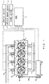
- Fig. 1 schematically shows an internal combustion engine to which the present invention is applied.
- the internal combustion engine 1 shown in Fig. 1 is a four-stroke cycle gasoline engine in which four cylinders 2 are arranged in a line.
- Each of the cylinders 2 of internal combustion engine 1 is provided with an intake valve 3, an exhaust valve 4 and an ignition plug 5.
- the internal combustion engine 1 is connected with an intake passage 6 and an exhaust passage 7.
- the intake passage 6 is in communication with each of the cylinders 2 of the internal combustion engine 1 via an intake port 8.
- a fuel injection valve 9 is attached to each intake port 8.
- the fuel injection valve 9 can inject fuel in the interior of the intake port 8.
- crank position sensor 11 is attached to the internal combustion engine 1.
- the crank position sensor is adapted to output a pulse signal every time an engine output shaft (i.e. a crankshaft) 10 rotates by a predetermined angle (for example 10 degrees).
- a crank pulley 12 is mounted on the crankshaft 10 of the internal combustion engine 1.
- the crank pulley 12 is connected with a motor pulley 102 fixed to the motor shaft 101 of a motor generator 100 by means of a belt 200.
- an electronic control unit (ECU) 13 for controlling the internal combustion engine 1.
- the ECU 13 is an arithmetic logical operation circuit composed of a CPU, a ROM, a RAM and a backup RAM etc..
- the ECU 13 is electrically connected with a starter switch 14, a vehicle speed sensor 15 and a brake switch 16 as well as the aforementioned crank position sensor 11 so that output signals of these portions are input to the ECU 13.
- the ECU 13 is electrically connected with the ignition plugs 5, the fuel injection valves 9 and the motor generator 100 mentioned above, so that the ECU 13 can control the ignition plugs 5, the fuel injection valves 9 and the motor generator 100.
- the ECU 13 causes the motor generator 100 to function as a generator.
- the rotational torque of the crankshaft 10 is transmitted to the motor shaft 101 via the crank pulley 12, the belt 200 and the motor pulley 102, so that the motor shaft 101 is rotated.
- the motor generator 100 generates electric power by converting the kinetic energy of the motor shaft 101 into electric energy.
- the ECU 13 upon starting the internal combustion engine 1, the ECU 13 causes the motor generator 100 to function as a motor.
- the motor generator 100 rotationally drives the motor shaft 101
- the rotational torque of the motor shaft 101 is transmitted to the crankshaft 10 via the motor pulley 102, the belt 200 and the crank pulley 12, so that the crankshaft 10 is rotated.
- the ECU 13 temporarily stops the operation of the ignition plugs 5 and the fuel injection valves 9 to stop the driving of the internal combustion engine 1 temporarily.
- the ECU 13 causes the motor generator 100 to operate as a starter motor and activates the ignition plugs 5 and the fuel injection valves 9 to start the internal combustion engine 1, to thereby restart the driving of the internal combustion engine 1.
- the ECU 13 is adapted to carry out, upon starting the internal combustion engine 1, the start control that will be described in the following.
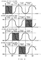
- the description will be made with reference to an exemplary case in which the ignition in the internal combustion engine 1 is performed in the following order: the first cylinder 2 - the third cylinder 2 - the fourth cylinder 2 - the second cylinder 2, and the rotational angle of the crankshaft 10 (which will be referred to as the crank angle hereinafter) becomes 0° (or 720°) when the first cylinder 2 is in the compression top dead center state.
- the ECU 13 controls to supply unburned air-fuel mixture into the cylinder 2 that will be on the expansion stroke when the driving of the internal combustion engine 1 is stopped (such a cylinder will be referred to as "the expansion stroke cylinder upon stoppage 2" hereinafter) in advance.
- the ECU 13 controls to suspend the operation of the ignition plugs 5 while continuing the operation of the fuel injection valves 9.
- the internal combustion engine 1 does not generate a torque for rotating the crankshaft 10, and therefore the crankshaft 10 rotates only with an inertial force.
- the ECU 13 determines the aforementioned expansion stroke cylinder upon stoppage 2.
- the method for determining the expansion stroke cylinder upon stoppage 2 can be exemplified by determination of the expansion stroke cylinder upon stoppage 2 based on the crank angle at the time when the driving of the internal combustion engine 1 is stopped, or more specifically, at the time when the rotation of the crankshaft 10 stops (such a crank angle will be referred to as the crank angle upon stoppage hereinafter).
- the first cylinder 2 when the crank angle is in the range of 0° to 180°, the first cylinder 2 is on the expansion stroke, when the crank angle is in the range of 180° to 360°, the third cylinder 2 is on the expansion stroke, when the crank angle is in the range of 360° to 540°, the fourth cylinder 2 is on the expansion stroke, and when the crank angle is in the range of 540° to 720°, the second cylinder 2 is on the expansion stroke.
- the ECU 13 can determine that the first cylinder 2 is the expansion stroke cylinder upon stoppage 2, when the crank angle is in the range of 180° to 360°, the ECU 13 can determine that the third cylinder 2 is the expansion stroke cylinder upon stoppage 2, when the crank angle is in the range of 360° to 540°, the ECU 13 can determine that the fourth cylinder is the expansion stroke cylinder upon stoppage 2, and when the crank angle is in the range of 540° to 720°, the ECU can determine that the second cylinder 2 is the expansion stroke cylinder upon stoppage 2.
- the ECU 13 Having determined the expansion stroke cylinder upon stoppage 2 in this way, the ECU 13 causes the ignition plug 5 of the expansion stroke cylinder upon stoppage 2 to operate.
- the ECU 13 may cause the ignition plugs 5 of all of the cylinders 2 to operate without determining the expansion stroke cylinder upon stoppage 2 at the time when the conditions for starting the internal combustion engine 1 are met.
- the number of engine revolutions at the time of the cranking (which will be referred to as the number of revolutions upon cranking hereinafter) is calculated based on the output signal of the crank position sensor 11. More specifically, the ECU 13 calculates the number of revolutions upon cranking based on the time intervals at which the cranking position sensor 11 outputs signal pulses.
- the ECU 13 determines whether or not the aforementioned number of revolutions upon cranking is equal to or larger than a predetermined number of revolutions.
- the predetermined number of revolutions mentioned above is, for example, substantially equal to or larger than the number of engine revolutions at the time when the motor generator 100 operates as a starter motor.
- the ECU 13 causes the ignition plugs 5 and the fuel injection valves 9 to operate without causing the motor generator 100 to operate as a motor.
- the internal combustion engine is started without utilizing the power of the motor generator 100.
- the ECU 13 causes the ignition plugs 5 and the fuel injection valves 9 to operate while causing the motor generator to operate as a motor.
- the internal combustion engine 1 is started utilizing the power of the motor generator 100.
- the load on the motor generator 100 is sufficiently lower than in the case that the unburned air-fuel mixture is not burned in the expansion stroke cylinder upon stoppage 2.
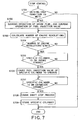
- Fig. 3 is a flow chart of a stop control routine
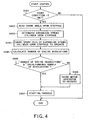
- Fig. 4 is a flow chart of a start control routine.
- the stop control routine is a routine executed by the ECU 13, triggered by the establishment of the driving stop conditions while the internal combustion engine 1 is driving.
- the start control routine is a routine executed by the ECU 13, triggered by the establishment of the driving start conditions while the internal combustion engine 1 is at rest.
- the ECU 13 firstly determines, in step S301, whether or not the driving stop conditions for the internal combustion engine 1 are met.
- the driving stop conditions can be exemplified as follows: the output signal of the brake switch 16 is on; and the output signal of the vehicle speed sensor 15 is "0".
- step S301 If it is determined in step S301 that the driving stop conditions are not met, the ECU 13 terminates the execution of this routine.
- step S301 determines whether the driving stop conditions are met. If it is determine in step S301 that the driving stop conditions are met, the process of the ECU 13 proceeds to step S302, and the ECU 13 suspends the operation of the ignition plugs 5. Namely, the ECU 13 suspends the operation of the ignition plugs 5 while maintaining the operation of the fuel injection valve 9.
- step S303 the ECU 13 calculates the number of engine revolutions based on the output signal of the crank position sensor 11.
- step S304 the ECU 13 determines whether or not the number of engine revolutions calculated in the aforementioned step S303 is "0", in other words, whether or not the rotation of the crankshaft 10 has stopped.
- step S304 If it is determined in step S304 that the number of engine revolutions is not "0”, the ECU 13 assumes that the rotation of the crankshaft 10 has not stopped, and executes the process of the aforementioned steps S303 and S304 again.
- step S304 determines that the number of engine revolutions is "0"
- the ECU 13 assumes that the rotation of the crankshaft 10 has stopped, and the process proceeds to step S305.
- step S305 the ECU 13 stores the crank angle at the time when the rotation of the crankshaft 10 stopped (i.e. the crank angle upon stoppage) in the backup RAM.
- step S306 the ECU13 suspends the operation of the fuel injection valves 9 and terminates the execution of this routine.
- air-fuel mixture is supplied to each of the cylinders 2 of the internal combustion engine 1 during the time period (the time period required for engine stop) from when the operation of the ignition plugs 5 is suspended until the rotation of the crankshaft 10 stops. Consequently, unburned air-fuel mixture is sealed in the interior of the cylinder (the expansion stroke cylinder upon stoppage) 2 that is on the expansion stroke at the time when the rotation of the crankshaft 10 stops.
- the ECU 13 will execute the start control routine shown in Fig. 4.
- the ECU 13 firstly determines, in step S401, whether or not the start conditions for the internal combustion engine 1 are met.
- the start condition mentioned above may be exemplified by switching of the brake switch 16 from ON to OFF and switching of the starter switch 14 from OFF to ON.
- step S401 If it is determined in step S401 that the start conditions are not met, the ECU 13 terminates the execution of this routine.
- step S401 determines whether the start conditions are met. If it is determined in step S401 that the start conditions are met, the process of the ECU 13 proceeds to step S402, and the ECU 13 reads out the crank angle upon stoppage from the backup RAM.
- step S403 the ECU 13 determines the expansion stroke cylinder upon stoppage 2 based on the aforementioned crank angle upon stoppage. In doing so, when the crank angle upon stoppage is in the range of 0° to 180°, the ECU 13 determines that the first cylinder 2 is the expansion stroke cylinder upon stoppage 2, when the crank angle is in the range of 180° to 360°, the ECU 13 determines that the third cylinder 2 is the expansion stroke cylinder upon stoppage 2, when the crank angle is in the range of 360° to 540°, the ECU 13 determines that the fourth cylinder 2 is the expansion stroke cylinder upon stoppage 2, and when the crank angle is in the range of 540° to 720°, the ECU 13 determines that the second cylinder 2 is the expansion stroke cylinder upon stoppage 2.
- step S404 the ECU 13 activates the ignition plug 5 of the expansion stroke cylinder upon stoppage 2 determined in the aforementioned step S403.
- the crankshaft 10 is rotated without utilizing the power of the motor generator 100.
- the cranking of the internal combustion engine 1 is achieved by the combustion of the air-fuel mixture in the interior of the expansion stroke cylinder upon stoppage 2.
- step S405 the ECU 13 calculates the number of revolutions of the cranking based on the output signal of the crank position sensor 11.
- step S406 the ECU 13 determines whether or not the number of revolutions of the cranking calculated in the aforementioned step S405 is equal to or larger than a predetermined number of revolutions.
- step S406 If it is determined in the aforementioned step S406 that the aforementioned number of revolutions of the cranking is equal to or larger than the predetermined number of revolutions, the process of the ECU 13 proceeds to step S407, in which the starting process is carried out.
- the ECU 13 causes the ignition plugs 5 and the fuel injection valves 9 to operate in a manner similar to the process in the normal starting.
- the internal combustion engine 1 is started without utilizing the power of the motor generator 100.
- step S406 determines that the aforementioned number of revolutions of the cranking is smaller than the predetermined number of revolutions. If it is determined in the aforementioned step S406 that the aforementioned number of revolutions of the cranking is smaller than the predetermined number of revolutions, the ECU 13 causes, in step S408, the motor generator 100 to operate as a motor, and subsequently executes the process of step S407.
- the internal combustion engine 1 is started by utilizing the combustion pressure generated upon combustion of the unburned air-fuel mixture in the interior of the expansion stroke cylinder upon stoppage 2 and the power of the motor generator 100.
- the cranking of the internal combustion engine 1 can be achieved utilizing the combustion pressure generated upon combustion of the unburned air-fuel mixture in the interior of the expansion stroke cylinder upon stoppage 2.
- the fuel injection valves 9 are caused to operate during the time period required for engine stop
- the operation of the fuel injection valves 9 may be suspended during the time period from when the operation of the ignition plugs 5 is suspended until the number of engine revolutions decreases to some degree within the time period required for engine stop.
- crankshaft 10 will stop after it has rotated several times since the time when the operation of the ignition plugs 5 is suspended, and therefore it is considered that the fuel injected from the fuel injection valves 9 just after the operation of the ignition plugs 5 is suspended will not be staying in the cylinders 2 of the internal combustion engine but exhausted.
- the start control may be modified in such a way that the cylinder 2 that is on the compression stroke at the time when the driving of the internal combustion engine stops (such a cylinder will be referred to as the compression stroke cylinder upon stoppage 2 hereinafter) is determined in addition to the cylinder that is on the expansion stroke (the expansion stroke cylinder upon stoppage), and the air-fuel mixture in the interior of the expansion stroke cylinder upon stoppage is burned firstly and the air-fuel mixture in the interior of the compression stroke cylinder upon stoppage is also burned subsequently at the time when the compression stroke cylinder upon stoppage gets on the expansion stroke.
- the compression stroke cylinder upon stoppage 2 such a cylinder will be referred to as the compression stroke cylinder upon stoppage 2 hereinafter
- the load on the motor generator 100 can be reduced further, since the cranking of the internal combustion engine 1 is achieved utilizing the combustion pressure generated upon combustion of the unburned air-fuel mixture in the interior of the compression stroke cylinder upon stoppage in addition to the combustion pressure generated upon combustion of the unburned air-fuel mixture in the interior of the expansion stroke cylinder upon stoppage.
- Fig. 5 is a flow chart of a stop control routine in this embodiment
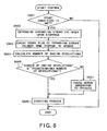
- Fig. 6 is a flow chart of a start control routine in this embodiment.
- the aforementioned stop control routine is a routine executed by the ECU 13, triggered by the establishment of the stop conditions while the internal combustion engine 1 is in the driving state as is the case with the stop control routine in the above-described first embodiment
- the aforementioned start control routine is a routine executed by the ECU 13, triggered by the establishment of the start conditions while the internal combustion engine 1 is at rest as is the case with the start control routine in the above-described first embodiment.
- the ECU 13 firstly determines, in step S501, whether or not the driving stop conditions for the internal combustion engine 1 are met.
- step S501 If it is determined in step S501 that the driving stop conditions are not met, the ECU 13 terminates the execution of this routine.
- step S501 determines that the driving stop conditions are met
- step S502 the process of the ECU 13 proceeds to step S502, and the ECU 13 suspends the operation of the ignition plugs 5 and the operation of the fuel injection valves 9.
- step S503 the ECU 13 estimates the expansion stroke cylinder upon stoppage 2.
- the method for estimating the expansion stroke cylinder upon stoppage 2 can be exemplified by a method of estimating the crank angle upon stoppage using as a parameter a crank angle at the time when the number of engine revolutions decreases dawn to a specific number of revolutions during the time period required for engine stop, in other words, at the time when the rotational speed of the engine decreases down to a specific rotational speed during the time period required for engine stop.
- the relationship between the crank angle at the time when the number of engine revolutions decreases down to the specific number of revolutions and the crank angle upon stoppage may be obtained in advance by an experiment and the relationship may be represented as a map.
- crank angle upon stoppage may be estimated using the temperature of the lubricant and the temperature of the cooling water as parameters in addition to the crank angle at the time when the number of engine revolutions decreases down to the specific number of revolutions.
- step S504 the ECU 13 activates the fuel injection valve 9 of the expansion stroke cylinder upon stoppage 2 estimated in the aforementioned step S503.
- step S505 the ECU 13 calculates the number of engine revolutions based on the output signal of the crank position sensor 11.
- step S506 the ECU 13 determines whether or not the number of engine revolutions calculated in the aforementioned step S505 is "0", namely whether or not the rotation of the crankshaft 10 has stopped.
- step S506 If it is determined in the aforementioned step S506 that the number of engine revolutions is not "0", the ECU 13 executes the process of the aforementioned steps S504 to S506 again.
- step S506 If it is determined in the aforementioned step S506 that the number of engine revolutions is "0", the ECU 13 assumes that the rotation of the crankshaft 10 has stopped, and the process proceeds to step S507.
- step S507 the ECU 13 stores information for identifying the expansion stroke cylinder upon stoppage 2 estimated in the aforementioned step S503 in the backup RAM.
- step S508 the ECU 13 suspends the operation of the fuel injection valve 9 of the expansion stroke cylinder upon stoppage 2 to finish the execution of this routine.
- the ECU 13 executes the start control routine shown in Fig. 6.
- the ECU 13 firstly determines in step S601, whether or not the start conditions for the internal combustion engine 1 are met.
- step S601 If it is determined in step S601 that the start conditions are not met, the ECU 13 terminates the execution of this routine.
- step S601 if it is determined in step S601 that the start conditions are met, the process of the ECU 13 proceeds to step S602, and the ECU 13 reads out information for identifying the expansion stroke cylinder upon stoppage 2 from the backup RAM and determines the expansion stroke cylinder upon stoppage 2 based on the identification information.
- step S603 the ignition plug 5 of the expansion stroke cylinder upon stoppage 2 determined in the aforementioned step S602 is caused to operate.
- the crankshaft 10 is rotated without utilizing the power of the motor generator 100.
- the cranking of the internal combustion engine 1 is achieved by the combustion of the air-fuel mixture in the interior of the expansion stroke cylinder upon stoppage 2.
- steps S604 to S607 is the same as the process of steps S405 to S408 of the start control routine in the above-described first embodiment.
- the cranking of the internal combustion engine 1 can be achieved utilizing the combustion pressure generated upon combustion of the unburned air-fuel mixture in the interior of the expansion stroke cylinder upon stoppage 2.
- the advantageous effects same as the above-described first embodiment can be achieved. Furthermore, since in the start control apparatus for an internal combustion engine according to this embodiment, the operation of the fuel injection valve 9 of only the expansion stroke cylinder upon stoppage 2 is caused to operate during the time period in which the number of engine revolutions changes from the specific number of revolutions to "0" within the time period required for engine stop, the fuel consumption can be reduced as compared to the start control apparatus for an internal combustion engine according to the above-described first embodiment.
- the ECU 13 may be adapted in such a way as to cause the motor generator 100 to operate to rotate the crankshaft 10 until the expansion stroke cylinder upon stoppage 2 gets on the expansion stroke.
- the ECU 13 determines, upon stoppage of the driving of the internal combustion engine 1 or upon the next start of the internal combustion engine 1, whether the expansion stroke cylinder upon stoppage 2 is on the compression stroke or on the expansion stroke based on the crank angle upon stoppage.
- the ECU 13 executes, upon the next start of the internal combustion engine 1, the start control routine as described with reference to Fig. 6 to start the internal combustion engine 1.
- the ECU 13 causes the motor generator 100 to operate until the aforementioned expansion stroke cylinder upon stoppage 2 gets on the expansion stroke, upon stoppage of the driving of the internal combustion engine 1 or upon the next start of the internal combustion engine 1. Furthermore, the ECU 13 causes to ignition plug 5 of the expansion stroke cylinder upon stoppage 2, upon the next start of the internal combustion engine 1.
- the motor generator 100 is caused to operate until the expansion stroke cylinder upon stoppage 2 shifts from the compression stroke to the expansion stroke, the operating time of the motor generator 100 on that occasion is very short as compared to the case in which the cranking is achieved by the motor generator 100 alone.
- the cranking of the internal combustion engine 1 can be achieved by combustion of the unburned air-fuel mixture in the interior of the expansion stroke cylinder upon stoppage 2. Therefore, the load on the motor generator 100 upon starting the engine can be reduced.
- the ECU 13 estimates the expansion stroke cylinder upon stoppage 2 during the time period required for engine stop and seals unburned air-fuel mixture in the interior of that expansion stroke cylinder upon stoppage
- the ECU 13 may be adapted in such a way as to estimate the cylinder 2 that will be on the compression stroke upon stoppage of the driving of the internal combustion engine 1 (such a cylinder will be referred to as the compression stroke cylinder upon stoppage 2 hereinafter) and to seal unburned air-fuel mixture in the interior of that compression stroke cylinder upon stoppage 2.
- the ECU 13 causes the ignition plug 5 of the compression stroke cylinder upon stoppage 2 to operate after causing the motor generator 100 to operate until the compression stroke cylinder upon stoppage 2 gets on the expansion stoke.
- the motor generator 100 is caused to operate until the compression stroke cylinder upon stoppage 2 shifts from the compression stroke to the expansion stroke, the operating time of the motor generator 100 on that occasion is very short as compared to the case in which the cranking is achieved by the motor generator 100 alone.
- the cranking of che internal combustion engine 1 can be achieved by combustion of the unburned air-fuel mixture in the interior of the expansion stroke cylinder upon stoppage 2. Therefore, the load on the motor generator 100 upon starting the engine can be reduced.
- the ECU 13 estimates the expansion stroke cylinder upon stoppage 2 during the time period required for engine stop and seals unburned air-fuel mixture in the interior of that expansion stroke cylinder upon stoppage 2, the ECU 13 may be adapted in such a way as to estimate the cylinder 2 (i.e. the compression stroke cylinder upon stoppage 2) that will be on the compression stroke in addition to the cylinder 2 (the expansion stroke cylinder upon stoppage 2) that will be on the expansion stroke upon stoppage of the driving of the internal combustion engine 1 and to seal unburned air-fuel mixture in the interior of the expansion stroke cylinder upon stoppage 2 and the compression stroke cylinder upon stoppage 2.
- the ECU 13 firstly causes the ignition plug 5 of the expansion stroke cylinder upon stoppage 2 to operate to rotate the crankshaft 10, and subsequently causes the ignition plug 5 of the compression stroke cylinder upon stoppage at the time when the compression stroke cylinder upon stoppage 2 gets on the expansion stroke.
- the cranking of the internal combustion engine 1 can be achieved utilizing the combustion pressure generated upon combustion of the unburned air-fuel mixture in the interior of the compression stroke cylinder upon stoppage 2 in addition to the combustion pressure generated upon combustion of the air-fuel mixture in the interior of the expansion stroke cylinder upon stoppage 2. Therefore, the load on the motor generator 100 upon starting the engine can be further reduced.
- the difference between this embodiment and the above-described first embodiment is that while in the above-described first embodiment the fuel injection valves 9 of all of the cylinders 2 are operated during the time period required for engine stop so that unburned air-fuel mixture is sealed in the interior of the cylinder 2 that is on the expansion stroke when the rotation of the crankshaft 10 stops, in this embodiment the fuel injection valve 9 of a specific cylinder 2 is caused to operate just before the rotation of the crankshaft 10 stops and the rotation of the crankshaft 10 is stopped at the time when the aforementioned specific cylinder 2 gets on the expansion stroke.
- Fig. 7 is a flow chart of a stop control routine in this embodiment
- Fig. 8 is a flow chart of a start control routine in this embodiment.
- the aforementioned stop control routine is a routine executed by the ECU 13, triggered by the establishment of the stop conditions while the internal combustion engine is in the driving state as is the case with the stop control routine in the above-described first embodiment
- the aforementioned start control routine is a routine executed by the ECU 13, triggered by the establishment of the start conditions while the internal combustion engine 1 is at rest as is the case with the start control routine in the above-described first embodiment.
- the ECU 13 firstly determines, in step S701, whether or not the driving stop conditions for the internal combustion engine 1 are met.
- step S701 If it is determined in step S701 that the driving stop conditions are not met, the ECU 13 terminates the execution of this routine.
- step S701 determines whether the driving stop conditions are met. If it is determine in step S701 that the driving stop conditions are met, the process of the ECU 13 proceeds to step S702, and the ECU 13 suspends the operation of the ignition plugs 5 and the operation of the fuel injection valves 9.
- step S703 the ECU 13 calculates the number of engine revolutions based on the output signal of the crank position sensor 11.
- step S704 the ECU 13 determines whether the number of engine revolutions calculated in the aforementioned step S703 has decreased to be equal to or lower than a specific number of revolutions that has been set in advance.
- step S704 If it is determined in the aforementioned step S704 that the number of engine revolutions has not decreased to be equal to or lower than the specific number of revolutions, the ECU 13 executes the process of the above-described steps S703 and S704 again.
- step S704 If it is determined in the aforementioned step S704 that the number of engine revolutions has decreased to be equal to or lower than the specific number of revolutions, the process of the ECU 13 proceeds to step S705, and the ECU 13 determines whether or not one cylinder 2 among the four cylinders (that cylinder will be referred to as a specific cylinder hereinafter) is on the intake stroke. For example, in the case that the specific cylinder 2 is the first cylinder 2, the ECU 13 can determine that the specific cylinder 2 is on the intake stroke on condition that the crank angle is in the range of 360° to 540°.
- the ECU 13 executes the process of the aforementioned S705 repeatedly until the aforementioned specific cylinder 2 gets on the intake stroke.
- step S705 If it is determined in the aforementioned step S705 that the aforementioned specific cylinder 2 is on the intake stroke, the process of the ECU 13 proceeds to step S706, and the ECU 13 causes the fuel injection valve 9 of the aforementioned specific cylinder 2 to operate.
- the time at which the fuel injection valve 9 of the specific cylinder 2 is caused to operate is not limited to a time at which the specific cylinder 2 is on the intake stroke, but it may be a time at which the specific cylinder 2 is on the exhaust stroke.
- step S707 the ECU 13 determines whether or not the aforementioned specific cylinder 2 is on the expansion stroke. For example, in the case that the specific cylinder 2 is the first cylinder 2, the ECU 13 can determines that the specific cylinder 2 is on the expansion stroke 2, on condition that the crank angle is in the range of 0° to 180°
- the ECU 13 executes the process of the aforementioned S707 repeatedly until the aforementioned specific cylinder 2 gets on the expansion stroke.
- step S707 If it is determined in the aforementioned step S707 that said specific cylinder 2 is on the expansion stroke, the process of the ECU 13 proceeds to step S708, and the ECU 13 executes a crankshaft stop process so as to stop the rotation of the crankshaft 10.
- the ECU 13 may cause, for example, the motor generator 100 to operate as a generator to stop the rotation of the crankshaft 10, or cause the motor generator 100 to rotate in the direction reverse to the rotation of the crankshaft 10 to stop the rotation of the crankshaft 10.
- the stop position of the crankshaft 10 be a position between the expansion stroke top dead center and the expansion stroke bottom dead center of the specific cylinder at which the pressure in the interior of the specific cylinder 2 is substantially equal to the atmospheric pressure.
- step S709 the ECU 13 stores information for identifying the aforementioned specific cylinder 2 in the backup RAM and finishes the execution of this routine.
- the aforementioned specific cylinder 2 be changed every time the driving of the internal combustion engine 1 is stopped.
- the ECU 13 will execute the start control routine shown in Fig. 8.
- the ECU 13 firstly determines in step S801 whether or not the start conditions for the internal combustion engine are met.
- step S801 If it is determined in the aforementioned step S801 that the start conditions are not met, the ECU 13 terminates the execution of this routine.
- step S801 if it is determined in the aforementioned step S801 that the start conditions are met, the process of the ECU 13 proceeds to step S802, and the ECU 13 reads the aforementioned information for identifying the specific cylinder 2 and determines the specific cylinder 2 in accordance with the identification information.
- step S803 the ECU 13 causes the ignition plug 5 of the specific cylinder 2 determined in the aforementioned step S802.
- the crankshaft 10 is rotated without utilizing the power of the motor generator 100.
- the cranking of the internal combustion engine 1 is achieved by the combustion of the air-fuel mixture in the interior of the expansion stroke cylinder upon stoppage 2.
- steps S804 to S807 is the same as the process of steps S405 to S408 of the start control routine in the above-described first embodiment.
- the cranking of the internal combustion engine 1 can be achieved utilizing the combustion pressure generated upon combustion of the unburned air-fuel mixture in the interior of the specific cylinder 2.
- the advantageous effects same as the above-described first embodiment can be achieved. Furthermore, in the start control apparatus for an internal combustion engine according to this embodiment, since it is possible to seal unburned air-fuel mixture in the interior of the specific cylinder 2 by causing the fuel injection valve 9 of the specific cylinder to operate only at once during the time period required for engine stop, the fuel consumption can be reduced as compared to the start control apparatus for an internal combustion engine according to the first embodiment.
- the ECU 13 may cause the motor generator to operate 100 so as to rotate the crankshaft 10 until the specific cylinder 2 gets on the expansion stroke.
- the ECU 13 determines whether the specific cylinder 2 is on the compression stroke or the expansion stroke based on the crank angle upon stoppage.
- the ECU 13 executes, upon the next start of the internal combustion engine 1, the start control routine as described with reference to Fig. 8 to start the internal combustion engine 1.
- the ECU 13 causes, upon stopping the driving of the internal combustion engine 1 or upon the next start of the internal combustion engine 1, the motor generator 100 to operate until the aforementioned specific cylinder 2 gets on the expansion stroke.
- the ECU 13 causes, upon the next start of the internal combustion engine 1, the ignition plug 5 of the specific cylinder to operate on condition that the specific cylinder 2 is on the expansion stroke.
- the motor generator 100 is caused to operate until the specific cylinder 2 shifts from the compression stroke to the expansion stroke, the operating time of the motor generator 100 on that occasion is very short as compared to the case in which the cranking is achieved by the motor generator 100 alone.
- the cranking of the internal combustion engine 1 can be achieved by combustion of the unburned air-fuel mixture in the interior of the expansion stroke cylinder upon stoppage 2. Therefore, the load on the motor generator 100 upon starting the engine can be reduced.
- the ECU 13 stops the rotation of the crankshaft 10 while the specific cylinder 2 is on the expansion stroke
- the ECU 13 may be adapted to stop the rotation of the crankshaft 10 while the specific cylinder 2 is on the compression stroke.
- the ECU 13 activates the ignition plug 5 of the specific cylinder 2 after causing the motor generator 100 to operate until the specific cylinder 2 gets on the expansion stroke.
- the internal combustion engine 1 be started forcibly at the time when the time elapsed since the stoppage of the driving of the internal combustion engine 1 becomes equal to or larger than a predetermined time.
- the internal combustion engine 1 is adapted to be forcibly started at the time when the time elapsed since the stoppage of the driving of the internal combustion engine 1 becomes equal to or larger than a predetermined value as described above, it is possible to prevent deterioration of combustibility of the air-fuel mixture in the interior of the expansion stroke cylinder upon stoppage 2 to thereby ensure combustion of the air-fuel mixture in the interior of the expansion stroke cylinder upon stoppage 2 upon starting the internal combustion engine 1.
- the start control apparatus of the present invention in an internal combustion engine provided with a fuel injection valve(s) for injecting fuel into an intake passage, it is possible to burn fuel in the interior of a cylinder upon starting the internal combustion engine, so that the internal combustion engine can be started utilizing a pressure generated upon combustion of the fuel.
Landscapes
- Engineering & Computer Science (AREA)
- Chemical & Material Sciences (AREA)
- Combustion & Propulsion (AREA)
- Mechanical Engineering (AREA)
- General Engineering & Computer Science (AREA)
- Combined Controls Of Internal Combustion Engines (AREA)
- Electrical Control Of Air Or Fuel Supplied To Internal-Combustion Engine (AREA)
- Output Control And Ontrol Of Special Type Engine (AREA)
- Control Of Vehicle Engines Or Engines For Specific Uses (AREA)
Applications Claiming Priority (5)
| Application Number | Priority Date | Filing Date | Title |
|---|---|---|---|
| JP2002307223 | 2002-10-22 | ||
| JP2002307223 | 2002-10-22 | ||
| JP2002371972 | 2002-12-24 | ||
| JP2002371972A JP3821090B2 (ja) | 2002-10-22 | 2002-12-24 | 内燃機関の始動制御装置 |
| PCT/JP2003/011161 WO2004038201A1 (ja) | 2002-10-22 | 2003-09-01 | 内燃機関の始動制御装置 |
Publications (3)
| Publication Number | Publication Date |
|---|---|
| EP1555411A1 true EP1555411A1 (de) | 2005-07-20 |
| EP1555411A4 EP1555411A4 (de) | 2009-04-15 |
| EP1555411B1 EP1555411B1 (de) | 2012-12-05 |
Family
ID=32179076
Family Applications (1)
| Application Number | Title | Priority Date | Filing Date |
|---|---|---|---|
| EP03809423A Expired - Lifetime EP1555411B1 (de) | 2002-10-22 | 2003-09-01 | Startsteuersystem für verbrennungsmotor |
Country Status (6)
| Country | Link |
|---|---|
| US (1) | US7028656B2 (de) |
| EP (1) | EP1555411B1 (de) |
| JP (1) | JP3821090B2 (de) |
| KR (1) | KR100630653B1 (de) |
| CN (1) | CN100359147C (de) |
| WO (1) | WO2004038201A1 (de) |
Cited By (2)
| Publication number | Priority date | Publication date | Assignee | Title |
|---|---|---|---|---|
| WO2007091735A1 (en) * | 2006-02-09 | 2007-08-16 | Toyota Jidosha Kabushiki Kaisha | Stop position control apparatus for internal combustion engine |
| EP1464833A3 (de) * | 2003-04-03 | 2008-06-11 | Continental Automotive GmbH | Verfahren zum Aufbereiten eines Luft-Kraftstoff-Gemisches für Direktstarts einer Brennkraftmaschine |
Families Citing this family (20)
| Publication number | Priority date | Publication date | Assignee | Title |
|---|---|---|---|---|
| DE602004012838T2 (de) * | 2003-01-27 | 2009-05-14 | Toyota Jidosha Kabushiki Kaisha, Toyota-shi | Steuervorrichtung für verbrennungsmotor |
| DE10322361A1 (de) * | 2003-05-09 | 2004-11-25 | Robert Bosch Gmbh | Verfahren und Vorrichtung zum Verbessern des Startverhaltens eines Verbrennungsmotors |
| JP4419655B2 (ja) * | 2004-04-08 | 2010-02-24 | 株式会社デンソー | エンジンの停止始動制御装置 |
| JP4345587B2 (ja) * | 2004-06-21 | 2009-10-14 | トヨタ自動車株式会社 | 内燃機関の機関始動制御システム |
| JP4539354B2 (ja) | 2005-02-04 | 2010-09-08 | 日産自動車株式会社 | 内燃機関の始動装置 |
| US7679360B2 (en) | 2005-03-14 | 2010-03-16 | Continental Automotive Systems Us, Inc. | Method for initializing increment position sensor |
| WO2006120760A1 (ja) | 2005-05-13 | 2006-11-16 | Toyota Jidosha Kabushiki Kaisha | 内燃機関の始動制御装置 |
| JP2006348826A (ja) * | 2005-06-15 | 2006-12-28 | Yanmar Co Ltd | 燃料噴射制御装置 |
| JP4277883B2 (ja) * | 2006-07-28 | 2009-06-10 | トヨタ自動車株式会社 | 筒内噴射式火花点火内燃機関 |
| JP2009007933A (ja) * | 2007-06-26 | 2009-01-15 | Mitsubishi Motors Corp | 内燃機関の始動装置 |
| US7610800B2 (en) * | 2007-08-29 | 2009-11-03 | Gm Global Technology Operations, Inc. | Method and system for collecting crankshaft position data |
| US8423271B2 (en) | 2011-11-09 | 2013-04-16 | Ford Global Technologies, Llc | Method for fueling an engine at start |
| FI123903B (en) * | 2012-10-24 | 2013-12-13 | Waertsilae Finland Oy | Internal combustion engine fluid detection system |
| DE112013006951B4 (de) * | 2013-04-16 | 2017-08-31 | Toyota Jidosha Kabushiki Kaisha | Fahrzeugsteuervorrichtung |
| DE102013210392A1 (de) * | 2013-06-05 | 2014-12-11 | Robert Bosch Gmbh | Verfahren zum Betreiben einer Verbrennungskraftmaschine |
| JP6191552B2 (ja) * | 2014-06-19 | 2017-09-06 | トヨタ自動車株式会社 | 内燃機関の自動停止制御装置 |
| JP6250484B2 (ja) * | 2014-06-20 | 2017-12-20 | 日立オートモティブシステムズ株式会社 | 内燃機関の自動停止/再始動制御システム及び可変動弁装置 |
| JP6485651B2 (ja) * | 2016-08-31 | 2019-03-20 | トヨタ自動車株式会社 | 内燃機関の制御装置 |
| JP2018193897A (ja) * | 2017-05-16 | 2018-12-06 | いすゞ自動車株式会社 | 制御装置および制御方法 |
| CN112228263B (zh) * | 2019-12-20 | 2022-05-17 | 株式会社电装 | 怠速启停系统和怠速启停的控制方法 |
Family Cites Families (19)
| Publication number | Priority date | Publication date | Assignee | Title |
|---|---|---|---|---|
| US6040634A (en) * | 1989-12-19 | 2000-03-21 | Larguier; Rene | Electric motor/thermal engine drive for a vehicle in which the electric motor functions as a flywheel, starter motor, and generator |
| IT1291361B1 (it) * | 1996-06-03 | 1999-01-07 | Bosch Gmbh Robert | Unita' di avvio ovvero di azionamento per un motore endotermico di un autoveicolo |
| JP3196646B2 (ja) * | 1996-07-18 | 2001-08-06 | トヨタ自動車株式会社 | 多気筒内燃機関の燃料噴射制御装置 |
| US6098585A (en) * | 1997-08-11 | 2000-08-08 | Ford Global Technologies, Inc. | Multi-cylinder four stroke direct injection spark ignition engine |
| DE19742969C2 (de) * | 1997-09-29 | 2002-08-14 | Siemens Ag | Verfahren zum Starten einer Mehrzylinderbrennkraftmaschine |
| DE19743492B4 (de) * | 1997-10-01 | 2014-02-13 | Robert Bosch Gmbh | Verfahren zum Starten einer Brennkraftmaschine insbesondere eines Kraftfahrzeugs |
| US5893349A (en) * | 1998-02-23 | 1999-04-13 | Ford Global Technologies, Inc. | Method and system for controlling air/fuel ratio of an internal combustion engine during cold start |
| DE19841752A1 (de) * | 1998-09-11 | 2000-03-16 | Bayerische Motoren Werke Ag | Verfahren zum Starten eines Verbrennungsmotors |
| US6593356B2 (en) * | 1999-10-20 | 2003-07-15 | Bristol-Myers Squibb Pharma Company | Acylsemicarbazides as cyclin dependent kinase inhibitors useful as anti-cancer and anti-proliferative agents |
| JP3661535B2 (ja) * | 1999-12-17 | 2005-06-15 | 三菱自動車工業株式会社 | 筒内噴射型エンジンの始動装置 |
| JP3714078B2 (ja) * | 1999-12-17 | 2005-11-09 | 三菱自動車工業株式会社 | 車両用エンジン自動始動制御装置 |
| JP2001342876A (ja) * | 2000-06-01 | 2001-12-14 | Toyota Motor Corp | 内燃機関自動停止始動制御装置 |
| JP3821202B2 (ja) * | 2000-06-16 | 2006-09-13 | 三菱自動車工業株式会社 | 筒内噴射型内燃機関の始動装置 |
| US6453864B1 (en) * | 2001-01-16 | 2002-09-24 | General Motors Corporation | Crankshaft rotation control in a hybrid electric vehicle |
| FR2827911B1 (fr) * | 2001-07-27 | 2004-01-30 | Peugeot Citroen Automobiles Sa | Procede de reglage de l'arret et procede de redemarrage d'un moteur a combustion interne |
| JP3571014B2 (ja) * | 2001-08-30 | 2004-09-29 | 本田技研工業株式会社 | 内燃機関の自動停止始動制御装置 |
| US6681173B2 (en) * | 2002-03-15 | 2004-01-20 | Delphi Technologies, Inc. | Method and system for determining angular crankshaft position prior to a cranking event |
| JP3815441B2 (ja) * | 2003-02-04 | 2006-08-30 | トヨタ自動車株式会社 | 内燃機関の停止始動制御装置 |
| JP3941705B2 (ja) * | 2003-02-13 | 2007-07-04 | トヨタ自動車株式会社 | 内燃機関の停止始動制御装置 |
-
2002
- 2002-12-24 JP JP2002371972A patent/JP3821090B2/ja not_active Expired - Fee Related
-
2003
- 2003-09-01 EP EP03809423A patent/EP1555411B1/de not_active Expired - Lifetime
- 2003-09-01 WO PCT/JP2003/011161 patent/WO2004038201A1/ja not_active Ceased
- 2003-09-01 KR KR1020057003686A patent/KR100630653B1/ko not_active Expired - Fee Related
- 2003-09-01 CN CNB038204290A patent/CN100359147C/zh not_active Expired - Fee Related
-
2004
- 2004-12-30 US US11/024,712 patent/US7028656B2/en not_active Expired - Lifetime
Cited By (4)
| Publication number | Priority date | Publication date | Assignee | Title |
|---|---|---|---|---|
| EP1464833A3 (de) * | 2003-04-03 | 2008-06-11 | Continental Automotive GmbH | Verfahren zum Aufbereiten eines Luft-Kraftstoff-Gemisches für Direktstarts einer Brennkraftmaschine |
| WO2007091735A1 (en) * | 2006-02-09 | 2007-08-16 | Toyota Jidosha Kabushiki Kaisha | Stop position control apparatus for internal combustion engine |
| US7809493B2 (en) | 2006-02-09 | 2010-10-05 | Toyota Jidosha Kabushiki Kaisha | Stop position control apparatus for internal combustion engine |
| CN101384810B (zh) * | 2006-02-09 | 2013-01-16 | 丰田自动车株式会社 | 用于内燃机的停止位置控制装置 |
Also Published As
| Publication number | Publication date |
|---|---|
| EP1555411A4 (de) | 2009-04-15 |
| CN1678824A (zh) | 2005-10-05 |
| CN100359147C (zh) | 2008-01-02 |
| KR100630653B1 (ko) | 2006-10-04 |
| JP2004197725A (ja) | 2004-07-15 |
| EP1555411B1 (de) | 2012-12-05 |
| US7028656B2 (en) | 2006-04-18 |
| KR20050035292A (ko) | 2005-04-15 |
| US20050115534A1 (en) | 2005-06-02 |
| WO2004038201A1 (ja) | 2004-05-06 |
| JP3821090B2 (ja) | 2006-09-13 |
Similar Documents
| Publication | Publication Date | Title |
|---|---|---|
| EP1555411B1 (de) | Startsteuersystem für verbrennungsmotor | |
| KR100871308B1 (ko) | 내연 기관의 제어 장치 | |
| US6877470B2 (en) | Starting control system of internal combustion engine and starting control method thereof | |
| JP4158583B2 (ja) | 内燃機関の始動装置 | |
| JP3941705B2 (ja) | 内燃機関の停止始動制御装置 | |
| US20090037085A1 (en) | Starting system and method of internal combustion engine | |
| JP2006029247A (ja) | エンジンの停止始動制御装置 | |
| JP5660143B2 (ja) | 内燃機関の制御装置 | |
| JP3951924B2 (ja) | 内燃機関の停止始動制御装置 | |
| JP2000205096A (ja) | 内燃機関のノック検出装置 | |
| JP2004346770A (ja) | 内燃機関の始動装置及び方法並びに動力システム | |
| JP4367646B2 (ja) | エンジンの始動装置 | |
| JP4701811B2 (ja) | 可変圧縮比内燃機関 | |
| JP4506764B2 (ja) | 内燃機関の停止始動制御装置 | |
| JP4059221B2 (ja) | 内燃機関の停止制御装置 | |
| JP2007056787A (ja) | 内燃機関の始動制御装置 | |
| JP2007278174A (ja) | 内燃機関の燃料カット制御装置 | |
| JP2009275576A (ja) | 内燃機関の制御装置 | |
| JP2009127539A (ja) | 内燃機関の停止制御装置 | |
| JP2005030217A (ja) | 車両の制御装置 | |
| JP2019060298A (ja) | 車両制御装置 | |
| JP2006200386A (ja) | 内燃機関の始動装置 | |
| JP2005330913A (ja) | 内燃機関 |
Legal Events
| Date | Code | Title | Description |
|---|---|---|---|
| PUAI | Public reference made under article 153(3) epc to a published international application that has entered the european phase |
Free format text: ORIGINAL CODE: 0009012 |
|
| 17P | Request for examination filed |
Effective date: 20050112 |
|
| AK | Designated contracting states |
Kind code of ref document: A1 Designated state(s): AT BE BG CH CY CZ DE DK EE ES FI FR GB GR HU IE IT LI LU MC NL PT RO SE SI SK TR |
|
| RBV | Designated contracting states (corrected) |
Designated state(s): DE FR GB IT |
|
| A4 | Supplementary search report drawn up and despatched |
Effective date: 20090312 |
|
| 17Q | First examination report despatched |
Effective date: 20091021 |
|
| GRAP | Despatch of communication of intention to grant a patent |
Free format text: ORIGINAL CODE: EPIDOSNIGR1 |
|
| GRAS | Grant fee paid |
Free format text: ORIGINAL CODE: EPIDOSNIGR3 |
|
| GRAA | (expected) grant |
Free format text: ORIGINAL CODE: 0009210 |
|
| RIN1 | Information on inventor provided before grant (corrected) |
Inventor name: ASADA, TOSHIAKI C/O TOYOTA JIDOSHA KABUSHIKI KAISH Inventor name: KUSAKA, YASUSHI C/O TOYOTA JIDOSHA KABUSHIKI KAISH Inventor name: MITANI, SHINICHI C/O TOYOTA JIDOSHA KABUSHIKI KAIS Inventor name: KATAOKA, KENJI C/O TOYOTA JIDOSHA KABUSHIKI KAISHA Inventor name: TSUJI, KIMOTOSHI C/O TOYOTA JIDOSHA KABUSHIKI KAIS |
|
| AK | Designated contracting states |
Kind code of ref document: B1 Designated state(s): DE FR GB IT |
|
| REG | Reference to a national code |
Ref country code: GB Ref legal event code: FG4D |
|
| REG | Reference to a national code |
Ref country code: DE Ref legal event code: R096 Ref document number: 60342784 Country of ref document: DE Effective date: 20130131 |
|
| RAP2 | Party data changed (patent owner data changed or rights of a patent transferred) |
Owner name: TOYOTA JIDOSHA KABUSHIKI KAISHA |
|
| PLBE | No opposition filed within time limit |
Free format text: ORIGINAL CODE: 0009261 |
|
| STAA | Information on the status of an ep patent application or granted ep patent |
Free format text: STATUS: NO OPPOSITION FILED WITHIN TIME LIMIT |
|
| 26N | No opposition filed |
Effective date: 20130906 |
|
| REG | Reference to a national code |
Ref country code: DE Ref legal event code: R097 Ref document number: 60342784 Country of ref document: DE Effective date: 20130906 |
|
| REG | Reference to a national code |
Ref country code: DE Ref legal event code: R084 Ref document number: 60342784 Country of ref document: DE |
|
| REG | Reference to a national code |
Ref country code: GB Ref legal event code: 746 Effective date: 20150618 |
|
| REG | Reference to a national code |
Ref country code: FR Ref legal event code: PLFP Year of fee payment: 14 |
|
| REG | Reference to a national code |
Ref country code: FR Ref legal event code: PLFP Year of fee payment: 15 |
|
| REG | Reference to a national code |
Ref country code: FR Ref legal event code: PLFP Year of fee payment: 16 |
|
| PGFP | Annual fee paid to national office [announced via postgrant information from national office to epo] |
Ref country code: BE Payment date: 20181031 Year of fee payment: 9 Ref country code: IT Payment date: 20180919 Year of fee payment: 16 |
|
| PGFP | Annual fee paid to national office [announced via postgrant information from national office to epo] |
Ref country code: GB Payment date: 20180829 Year of fee payment: 16 |
|
| PG25 | Lapsed in a contracting state [announced via postgrant information from national office to epo] |
Ref country code: IT Free format text: LAPSE BECAUSE OF NON-PAYMENT OF DUE FEES Effective date: 20190901 |
|
| GBPC | Gb: european patent ceased through non-payment of renewal fee |
Effective date: 20190901 |
|
| PG25 | Lapsed in a contracting state [announced via postgrant information from national office to epo] |
Ref country code: GB Free format text: LAPSE BECAUSE OF NON-PAYMENT OF DUE FEES Effective date: 20190901 Ref country code: FR Free format text: LAPSE BECAUSE OF NON-PAYMENT OF DUE FEES Effective date: 20190930 |
|
| PGFP | Annual fee paid to national office [announced via postgrant information from national office to epo] |
Ref country code: DE Payment date: 20210727 Year of fee payment: 19 |
|
| REG | Reference to a national code |
Ref country code: DE Ref legal event code: R119 Ref document number: 60342784 Country of ref document: DE |
|
| PG25 | Lapsed in a contracting state [announced via postgrant information from national office to epo] |
Ref country code: DE Free format text: LAPSE BECAUSE OF NON-PAYMENT OF DUE FEES Effective date: 20230401 |